

Page 1

xx
RF Generic Signal
ZZZ
Plug-in Application
Printable Help Document
Revision A
*P077124702*
077-1247-02
Page 2

Page 3

RF Generic Signal
Plug-in Application
ZZZ
Printable Help Document
Revision A
w.tek.com
ww
077-1247-02
Page 4

Copyright © Tektronix. All rights reserved. Licensed software products are owned by Tektronix or its
subsidiaries or suppliers, and are protected by national copyright laws and international treaty provisions.
Tektronix products are covered by U.S. and foreign patents, issued and pending. Information in this
publication supersedes that in all previously published material. Specifications and price change privileges
reserved.
TEKTRONIX and TEK are registered trademarks of Tektronix, Inc.
®
SourceXpress
is a registered trademark of Tektronix, Inc.
Microsoft and Windows are registered trademarks of Microsoft Corporation.
Supports RF Generic Signal plug-in Version 3.1.x and above.
Help part number: 076–0396–02
PDF of Help system part number: 077–1247–02
Contacting Tektronix
Tektronix, Inc.
14150 SW Karl Braun Drive
P. O . B o x 50 0
rton, OR 97077
Beave
USA
For product information, sales, service, and technical support:
In North America, call 1-800-833-9200.
Worldwide, visit ww w.tek.com to find contacts in your area.
Page 5

Table of Contents
Introduction
Welcome............................................................................................................. 1
Key features ......................................................................................................... 2
Documentation......................................... ................................ ............................. 3
Support information....... .................................. ................................ ....................... 3
Orientation
Elements of the display ............................................................................................ 5
Plug-in selection ....................................... ................................ ............................. 5
Signal Format selection........... ................................ .................................. ............... 6
Compile button..................... ................................ ................................ ................. 6
Reset Plug-in button....... ................................ ................................ ........................ 12
Help button............... .................................. ................................ ........................ 12
Table of Contents
Carrier list
Carrier list .................. ................................ .................................. ...................... 13
Add Carrier button..... .................................. ................................ .......................... 14
Add Multiple Carriers... button . . . . . . ............................................................................ 14
Setup tab
Setup tab .............................. ................................ ................................ .............. 17
Common Setup parameters....................................................................................... 17
Digital Modulation setup ......................................................................................... 18
Analog Modulation setup......................................................................................... 21
Noise setup ......................................................................................................... 22
Custom Modulation setup .......... ................................ ................................ .............. 22
PRBS Editor........................................................................................................ 25
Modulation types supported...................................................................................... 26
Hopping
Hopping............................. ................................ .................................. .............. 27
IQ Impairments
IQ Impairments .................................................................................................... 31
Power Ramp
Power Ramp........................................................................................................ 33
RF Generic Signal Printable Help Document i
Page 6

Table of Contents
Interference Addition
Interference Addition. . . . . . . . . . . . . . . . . . . . . . . . . . . . . . . . . . . . .......................................................... 35
Distortion
Distortion ................. .................................. ................................ ........................ 37
MultiPath
MultiPath . .......................... .. . . . . . . . . . . . . . . . . . . . . . . . . . . . . . . . . . . . . . . . . .......................... .. . . . . . . . . . . 39
Symbol mapping
Symbol mapping........... .................................. ................................ ...................... 41
Sub Carrier Modulation tab
Sub Carrier Modulation tab....................................................................................... 43
S-Parameter tab
S-Parameter license ............................................................................................... 45
S-Parameter tab ...................... .................................. ................................ ............ 45
S-Parameter file descriptions .................. ................................ .............................. 48
Aggressor signals ............................................................................................. 50
Licensing
Licensing ........................................................................................................... 51
Index
ii RF Generic Signal Printable Help Document
Page 7
Introduction Welcom e
Welcome
The RF Generic Waveform plug-in is a waveform creation application that is used to create digitally
modulated signals with multiple carriers.
The RF Generic Waveform plug-in is designed to integrate and operate seamlessly as an enhancement to
the following products:
SourceXpress waveform creation software
AWG70000 series arbitrary waveform generators
AWG5200 series arbitrary waveform generators
Once installed, the plug-in becomes available as another waveform plug-in application.
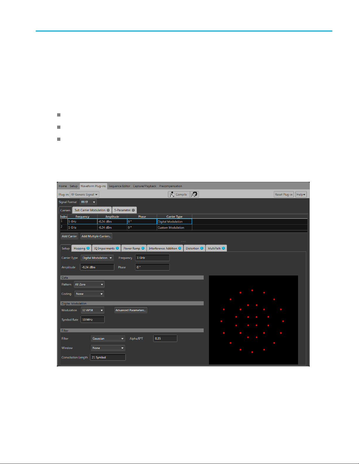
This illu
plug-in interface is identical whether it is used from SourceXpress or installed on a generator.
stration shows the RF Generic Waveform plug-in viewed from the SourceXpress application. The
RF Generic Signal Printable Help Document 1
Page 8

Introduction Key features
Key features
Define different kinds of waveforms. Create a variety of signals, such as: signals with Digital
Modulation, signals with Analog Modulation, Noise signals, and signals with Custom Modulation.
Multi-carrier setup. Define multiple RF/IF or IQ carriers in a single waveform. Each carrier can be
independently defined with parameters.
Baseband data generation. Define baseband I and Q signals using a variety of modulation schemes.
Substantial list of modulation types supported. For example, digital modulation types such as PSK,
APSK, QAM, GMSK, FSK, CPM, ASK, and OOK are supported.
IQ impairments. Apply impairments including quadrature error and quadrature imbalance.
Noise/interference generation and addition. Generate and add interference for waveforms.
Elimin
signals that c an be played back continuously.
Add sub
Provide S-parameter emulation of RF components.
Add Impairments. Multipath, Sinusoidal Interference, Frequency offset, and Non Linear Amplifier
Distortion.
Define frequency hopping.
ates the wrap-around effects found in arbitrary waveform generators, providing seamless
-carrier modulation.
2 RF Generic Signal Printable Help Document
Page 9

Introduction Documentation
Documentation
In addition to this application Help system, the following documentation is available for the software.
All documentation is available on the Tektronix Web site (www.tek.com/manual/downloads
To read about Use these documents
RF Generic plug-in operation and user interface
help
RF Generic plug-in programmer commands Access the plug-in programmer manual for the syntax of remote commands
SourceXpress operation and user interface help Access the SourceXpress application help from the Help menu for
SourceXpress programmer commands Access the SourceXpress programmer manual for the syntax of remote
Connected instrument operation and user
interface help (such as an AWG70000 series
generator)
Access the plug-in application help from the plug-in Help menu for
information on all controls and elements on screen.
The RF Generic plug-in help system is also available in PDF format located
in the program’s installation folder and also available on the Tektronix web
site.
specific to the plug-in.
This is available on the Tektronix web site.
information on all controls and elements on screen.
The SourceXpress help system is also available in PDF format, available
on the Tektronix web site.
commands.
This document is available in PDF format located in the program’s
installation folder and also available on the Tektronix web site.
For operation and interface help of a connected instrument, refer to the
instrument’s documentation.
This is available with the instrument or on the Tektronix web site.
).
Connected instrument programmer commands
(such as an AWG70000 series generator)
xxx
Support information
Tektronix offers the following services in support of their products:
Technical Support. For application-related questions about a Tektronix product, contact us by
telephone or email ).
Service Support. For service-related questions about a Tektronix product, contact us by telephone
or email ).
Tektronix also offers extended warranty and calibration programs as options on many products. Contact
your local Tektronix distributor or sales office.
For programming information of a connected instrument, refer to the
instrument’s documentation. This is available with the instrument or on
the Tektronix web site.
RF Generic Signal Printable Help Document 3
Page 10

Introduction Support information
4 RF Generic Signal Printable Help Document
Page 11

Orientation Elements of the display
Elements of the display
The main areas of the application window are shown in the following figure.
Plug-in selection
Use the Plug-in pull-down menu to select the RF Generic Signal plug-in application. The plug-in
pull-down menu varies depending the installed applications.
E. RF Generic Signal requires a license to create waveforms.
NOT
Refer to Licensing
RF Generic Signal Printable Help Document 5
(see page 51).
Page 12
Orientation Signal Format selection
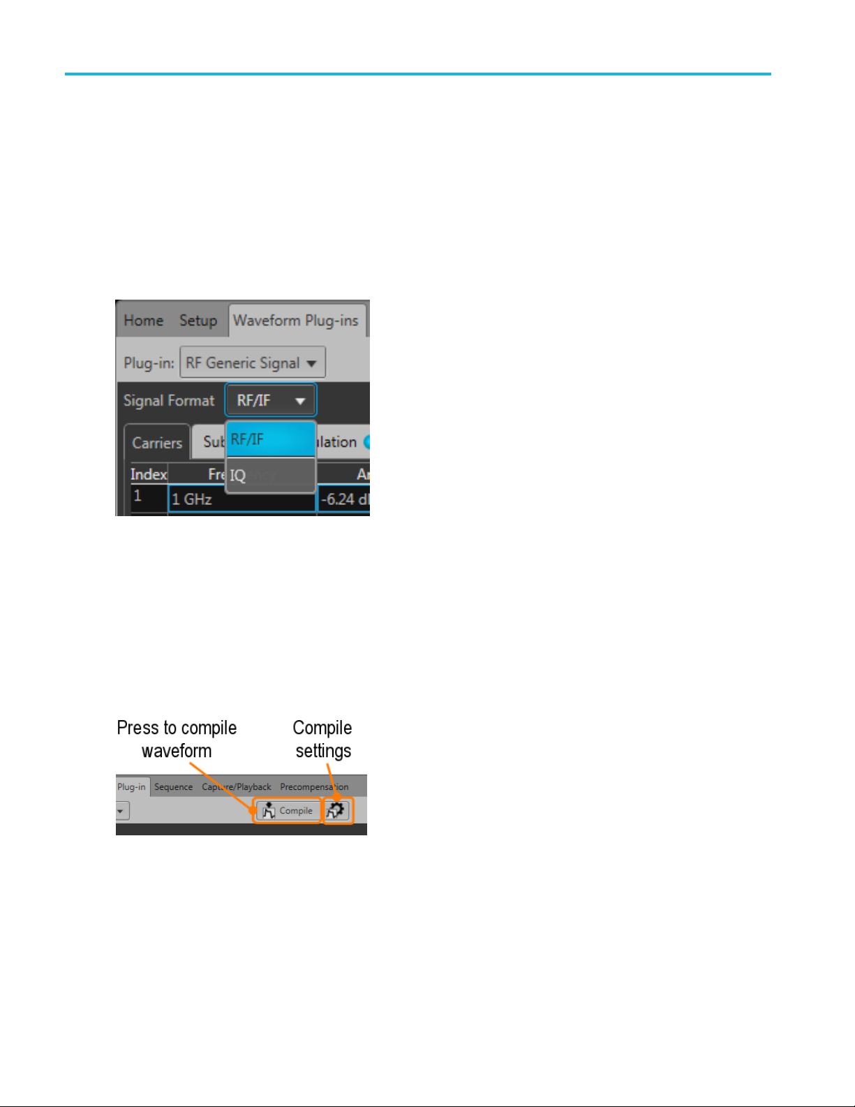
Signal Format selection
The RF Generic Signal plug-in provides the capability to create digitally modulated signals in either
RF/IF format or IQ format.
With RF/IF selected, a single waveform is created. With IQ selected, two waveforms are created, one for
I and one for Q.
Use the Signal Format pull-down list to select.
Compile button
Use the Compile button to create the waveforms and place the waveforms into the Waveforms list of the
pplication.
host a
Use the Compile settings button to edit the compilation settings.
6 RF Generic Signal Printable Help Document
Page 13

Orientation Compile button
Compile settings
Item Description
Name
Overwrite e xisting
waveform
The application provides a base name for compiled waveforms. You can edit the field
with a name of your choice. The waveform is added to the Waveforms list. If the name
already exists, the name is incremented with a numerical value (unless the overwrite
option is selected).
RF waveforms are appended with _RF. IQ waveforms are appended with _I and _Q.
The Reset Plug-in button resets the Name field to the default name.
If checked, a waveform with the same name (in the waveforms list) is overwritten with no
warnings.
RF Generic Signal Printable Help Document 7
Page 14
Orientation Compile button
Item Description
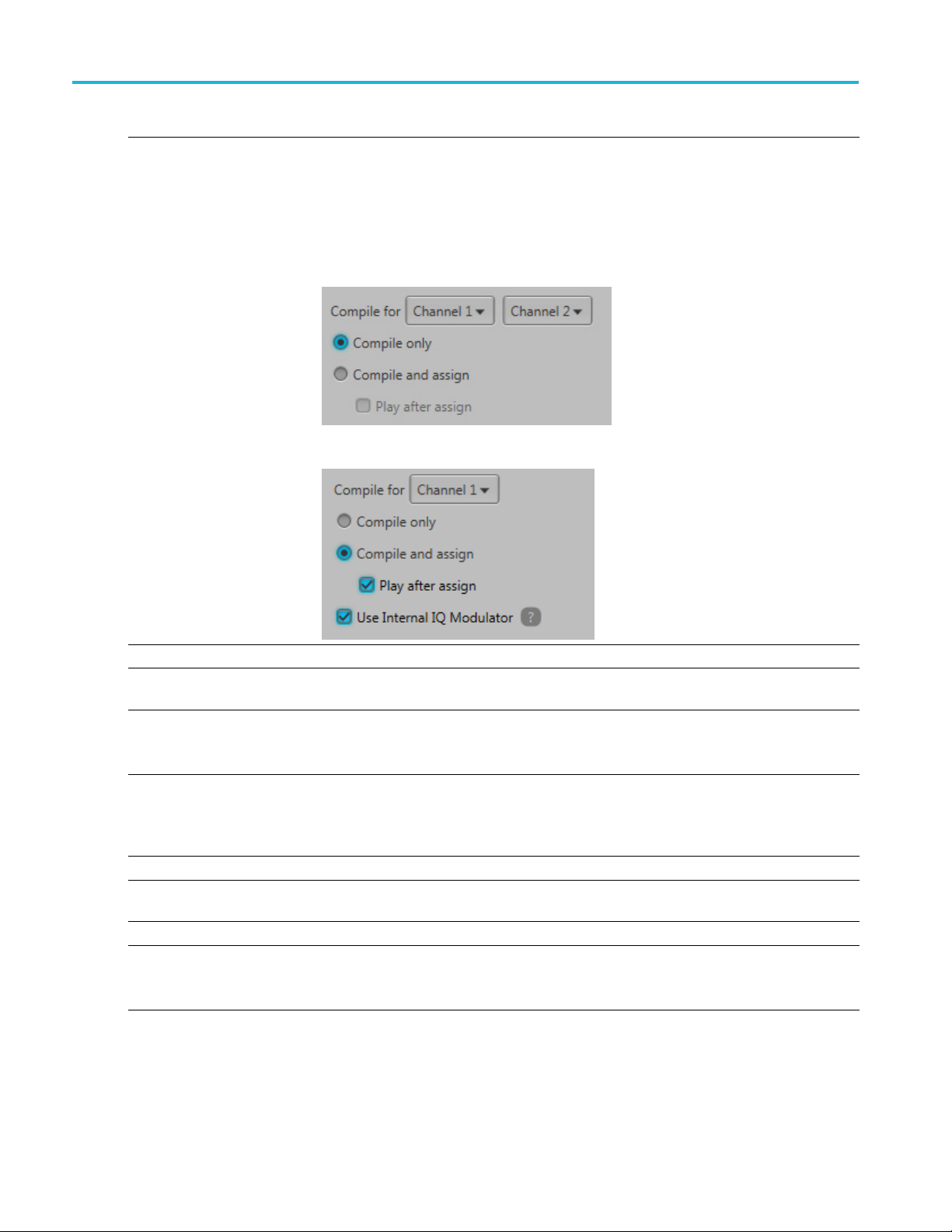
Compile for Signal Format = RF/IF
Choose the cha
also used to define the amplitude ranges.
The available channels is dependent on the generator model.
Signal Forma
When compiling IQ signals, you are presented with two channel selections.
The first channel selection is I, the second selection is Q.
If the generator has IQ modulator capabilities (digital up converter) and the IQ modulator is
enabled, a single channel selection is presented and a complex IQ waveform is created.
nnel to associate with the compiled w aveform. The selected channel is
t=IQ
Compile only The compiled waveforms are simply entered into the Waveforms list.
Compile and assign The compiled waveforms are entered into the Waveforms list and automatically assigned
to a selected channel.
Play after assign If checked, the waveform starts to play out immediately after compiling.
The instrument’s sample rate and amplitude will change based on the compiled waveform’s
properties.
Use Internal IQ Modulator If checked, a complex IQ Waveform is created which can be used with the internal
IQ modulator. Sampling Rate and interpolation rates will be calculated based on the
Baseband parameters.
This setting is not shown if the generator does not have an internal IQ modulator.
Sampling Rate
Auto calculate
Manual
Oversampling Select to increase the apparent sampling rate.
This is the default method to set the sampling rate. The application creates a sampling
rate based on the settings chosen for the waveform.
Select to enter a specific sampling rate.
The Sampling Rate is calculated by multiplying Oversampling with the maximum frequency
of the signal to be generated.
8 RF Generic Signal Printable Help Document
Page 15

Orientation Compile button
Item Description
Auto calculate waveform
length
Waveform length Directly enter the waveform length of the compiled waveform. The length can be defined
Set Marker Data Select to include markers in the compiled waveform.
or wrap-around
Adjust f
Fit to full dynamic range When checked, the waveform is normalized to make use of the full dynamic range of the
Corrections File
Apply
RF/IF Signal Format With the signal format set to RF/IF, the correction file dialog lets you select a single
When checked, the waveform length is calculated based on all settings chosen for the
waveform.
Uncheck to enter the waveform length manually.
as:
Samples
Symbols
Time
Symbols can
Custom Modulation.
Marker can be set to:
Symbol Rat
Bit Rate
Clock Frequency (when selected, enter the clock frequency from 1 Hz to the m aximum
sampling
When a wa
important to take care of the phase continuity between the start and end of the waveform.
Discontinuity in the waveform produces frequency spurs.
The appl
properties to make the phase continuous at the end and beginning of the waveform.
DAC. You might not get the set amplitude in cases w here the set amplitude requires the
wavef
Check
The correction file dialog changes depending on the Signal Format, RF/IF or IQ.
correction file to apply.
be defined only if the first Carrier Type is set to Digitally Modulation or
e
rate)
veform is in continuous play mode, it repeats when the end is reached. It is
ication might adjust the Sampling Rate, waveform length, and other waveform
ormtobescaled.
the box to apply a correction file directly to the waveform when compiling.
Use the browse folder icon to navigate to a saved correction file.
Onceavalidfile path is entered, the Correction Settings icon
display the Frequency Response screen.
is enabled. Select to
RF Generic Signal Printable Help Document 9
Page 16
Orientation Compile button
Item Description
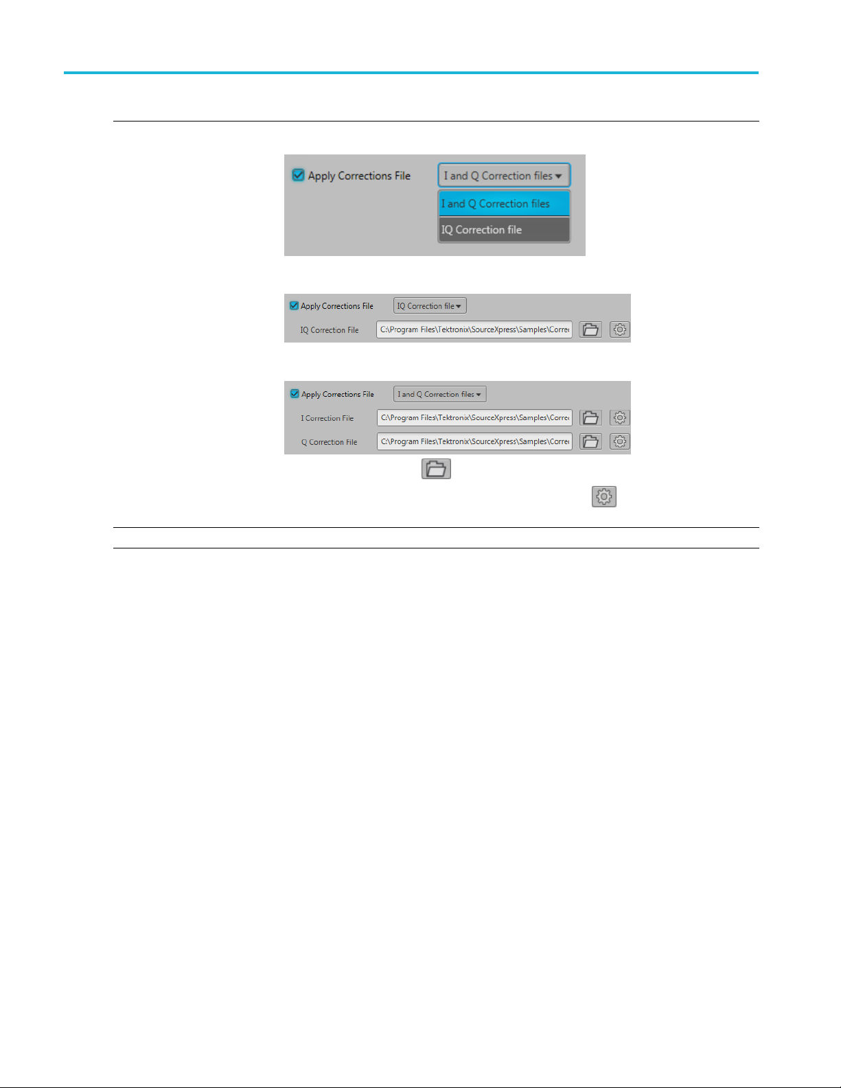
IQ Signal Format With the signal format set to IQ, the correction file dialog allows you to apply a correction
file to the IQ wa
When applying an IQ correction file, the correction file dialog lets you select a single
correction
When applying an I and Q correction files, the correction file dialog lets you select
individual correction files to apply.
veform or to the individual I and Q components of the waveform.
file to apply.
Use the b
rowse folder icon
Onceavalidfile path is entered, the Correction Settings icon
to navigate to a saved correction file.
is enabled. Select to
display the Frequency Response screen.
Compile Compiles the waveform.
xxx
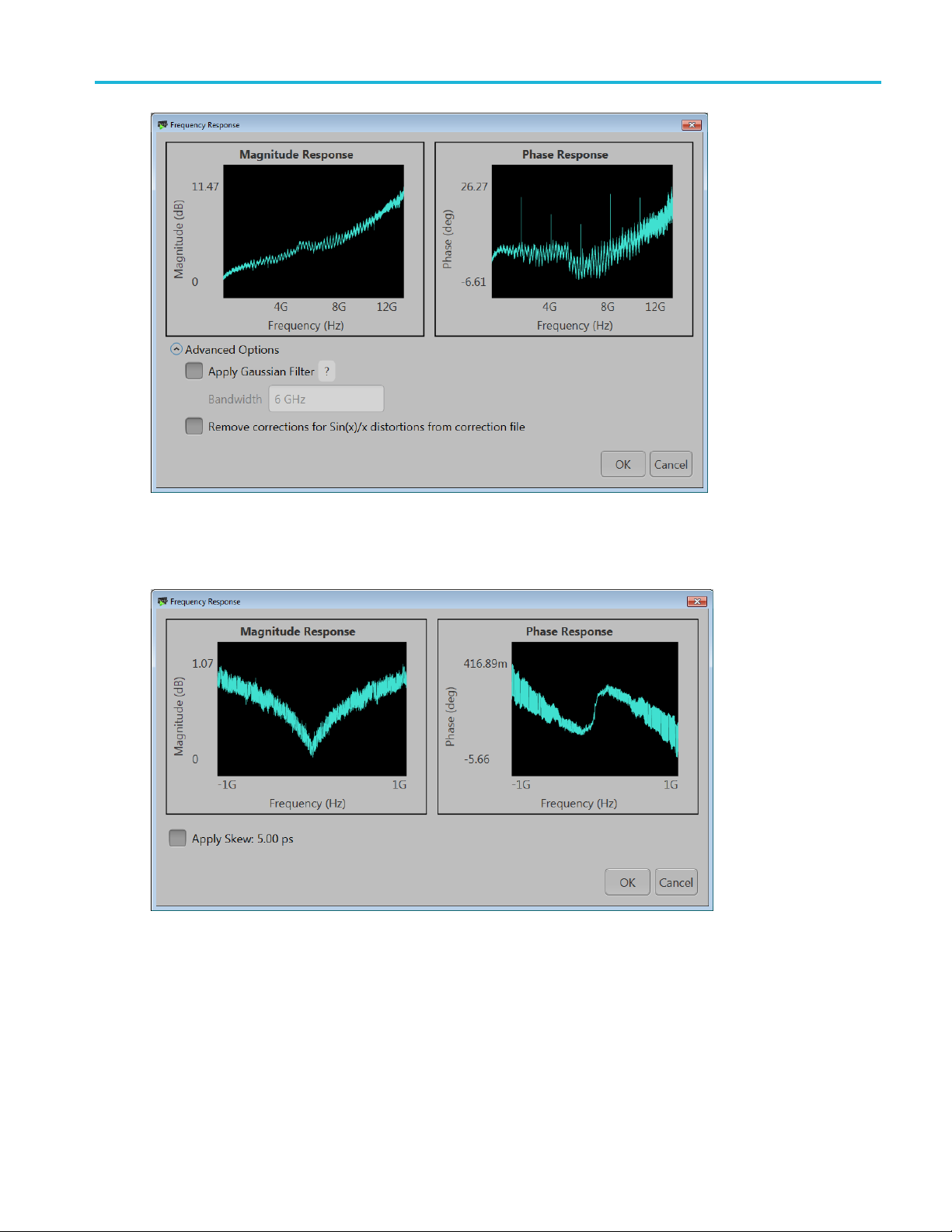
Correction file frequency response
If applying an RF correction file, the Frequency Response screen shows plot information and provides
Advanced options to apply a Gaussian filter or remove Sin(x)/x distortions.
10 RF Generic Signal Printable Help Document
Page 17
Orientation Compile button
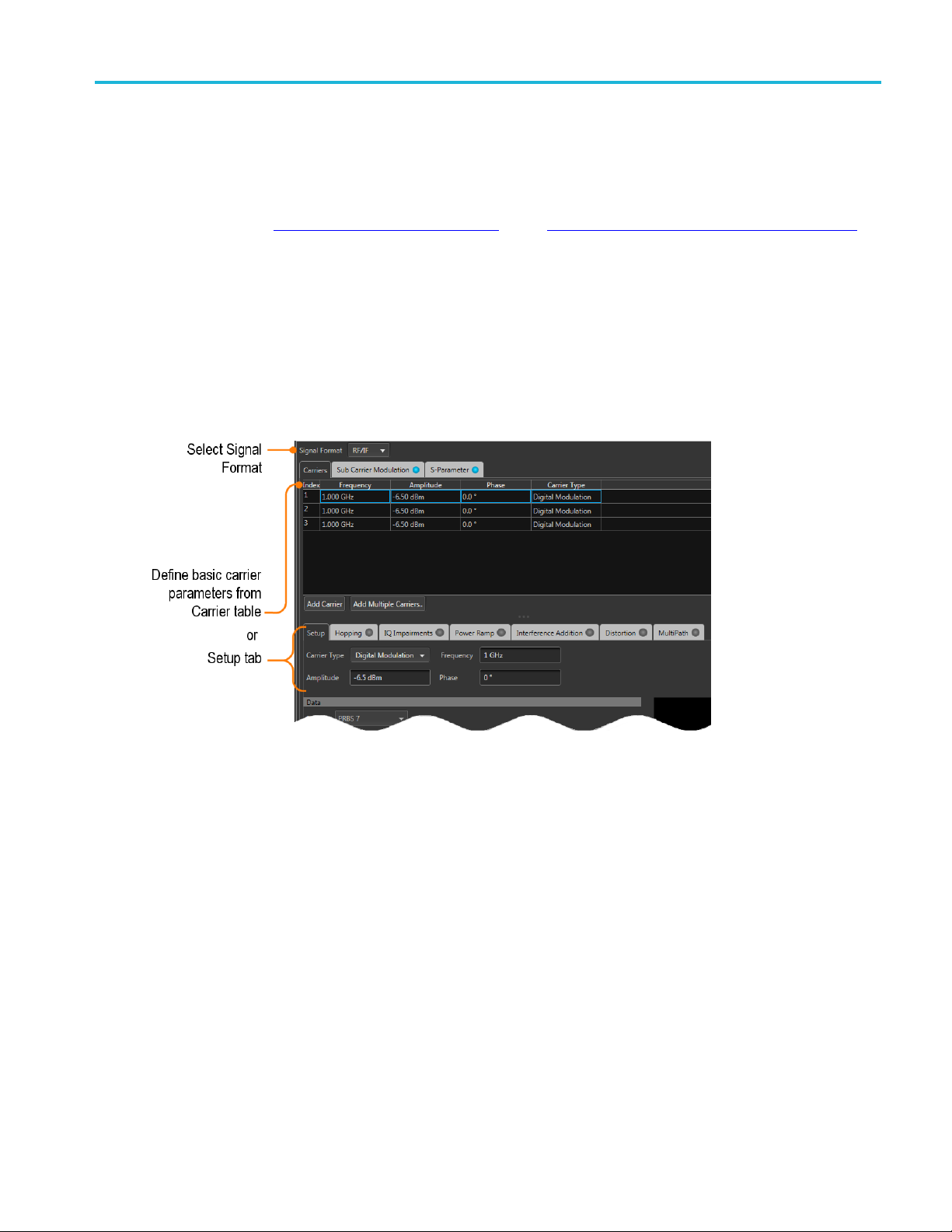
If applying an I/Q correction fi le (to a pair of I and Q waveforms), the Frequency Response screen shows
plot information and provides Advanced options to apply a skew.
RF Generic Signal Printable Help Document 11
Page 18

Orientation Reset Plug-in button
Reset Plug-in button
Returns all plug-in settings to their d efault values.
Help button
Help button: Provides links where you can obtain additional product help and documentation.
Item Description
User manual
About ...
xxx
Opens the plug-in help system.
Provides you with information about your plug-in application. This information is
helpful when contacting Tektronix about your application.
12 RF Generic Signal Printable Help Document
Page 19
Carrier list Carrier list
Carrier list
Initially, the RF Generic Plug-in contains one default carrier in the list of carriers. You can create additional
carriers using the Add Carrier button
The maximum number of carriers you can have in the table is 1024. Each row in the table corresponds to
one carrier.
Each carrier has a basic set of parameters (Frequency or Baseband Offset, Amplitude, Phase, and Carrier
Type). Frequency or Baseband Offset is available based on the Signal Format of RF/IF or IQ, respectively.
There are t
or by selecting a Carrier and use the Setup tab.
wo ways to set these parameters: within the Carriers table by double clicking in a table cell
(see page 14) or the Add Multiple Carriers... button (see page 14).
As you can
Carrier index list.
The Parameters shown in the Setup tab reflect the selected (Highlighted).
see in the User Interface, the Setup tab has the same settings as the column heads in the
Menu operations
With any carrier selected, a right-mouse click displays a menu of operations.
RF Generic Signal Printable Help Document 13
Page 20

Carrier list Add Carrier button
Item Description
Copy Copies the selected carrier (or carriers) in preparation to paste into the carrier list.
Carriers can only be selected in a contiguous manner.
Paste
Paste-Insert
Remove
xxx
Select the carrier to replace with the copied carrier.
If pasting multiple carriers, the selected carrier is replaced and the remaining carriers are inserted
below.
The copied carrier (or carriers) are inserted above the selected carrier.
The selected carrier (or carriers) are deleted.
You can also press Delete on the keyboard.
To select multiple carriers, left-mouse click on a carrier, continue to hold the left-mouse button
and slide the selection either up or down to highlight the c arriers. You can also select multiple
carriers by highlighting a carrier, hold the Shift key, and scroll up or down to the next carrier you
want to select.
Carriers can only be selected in a contiguous manner.
Add Carrier button
Selecting Add Carrier creates a single carrier, adding it to the list of carriers. The new carrier is placed at the
bottom of the existing carriers. All features and parameters of the new carrier are set to their default values.
Add Multiple Carriers... button
The Add Multiple Carriers... button displays a dialog box that allows you to e asily create many carriers.
All carriers are created using the same basic setup parameters except for the capability to vary frequency
and phase parameters between each carrier.
The Signal Format selection (RF/IF or IQ) determines the dialog display.
14 RF Generic Signal Printable Help Document
Page 21

Carrier list Add Multiple Carriers... button
Item Description
Number of carriers Select the number of carriers to add. The total number of carries possible is 1024.
RF/IF signal format
Center Frequency Choose between Center Frequency settings or Base Frequency settings.
Frequency
Bandwidth
Base Freque
ncy
Frequency
Carrier Spacing
Use Random Phases
IQ signa
Initial
lformat
Offset
Carrier Spacing
Common elements for RF/IF and IQ signal formats
Use Ran
dom Phases
Setup for the new carriers to be added
rtoSetup
Refe
arriers button
Add C
lace Carriers
Rep
(see page 17) for descriptions of each carrier type and the specific carrier type parameters.
button
xxx
Enter the center frequency of the carrier.
Range: 1 Hz to
Enter the ba
the maximum supported by the AWG.
ndwidth of the carrier.
Range: 1 Hz to the maximum supported by the AWG.
Choose between Base Frequency settings or Center Frequency settings.
Enter the base frequency of the carriers.
Range: 1 Hz to the maximum supported by the AWG.
Enter the spacing between carriers.
Range: 1 Hz to the maximum supported by the AWG.
If selected, the carriers will each have a random phase value.
lected, enter a phase value to be used by all new carriers. Range: –180° to +180°.
If not se
e initial baseband frequency. Each additional carrier created will have its frequency
Enter th
incremented by the carrier spacing.
he spacing between carriers.
Enter t
Range: 1 Hz to the maximum supported by the AWG.
If selected, each carrier is created with a random phase value.
If not selected, enter a phase value to be used by all new carriers. Range: –180° to +180°.
ct to add the carriers to the end of the existing list of carriers.
Sele
ect to delete all existing carriers and add the new carriers.
Sel
RF Generic Signal Printable Help Document 15
Page 22

Carrier list Add Multiple Carriers... button
16 RF Generic Signal Printable Help Document
Page 23

Setup tab Setup tab
Setup tab
The setup tab provides all the basic parameters for each carrier. As you highlight carriers i n the carrier list,
the Setup tab changes to match the highlighted carrier.
The example shows the Setup tab dialog screen with Digital Modulation as the carrier type.
NOTE. When adding a carrier (with the Add Carrier
default set
setup parameters.
To create c
page 14) button.
tings. After the new carrier is created, you can then change it’s carrier type and associated
arriers with settings other than the default settings, use the Add Multiple Carriers...
(see page 14) button), the new carrier is created with
(see
Common Setup parameters
The following settings are common setup parameters for carriers. As the Carrier Type changes, the Setup
tab changes to include parameters specific to the selected Carrier Type.
RF Generic Signal Printable Help Document 17
Page 24

Setup tab Digital Modulation setup
Item Description
Carrier Type The Carrier Type determines the available setup parameters. For setup information specificto
pe, refer to the following topics:
(see page 18)
ge
22)
for RF/IF signal format.
ignal Format is set to IQ, this shifts the IQ phase.
Offset
or
Frequency
Amplitude
or
Amplitude (Vrms)
Phase
xxx
the Carrier Ty
Digital Modulation
Analog Modulation (see page 21)
Noise (see pa
Custom Modulation (see page 22)
Frequency for RF/IF signal format.
Offset for IQ signal format.
Amplitude
Amplitude (rms) for IQ signal format.
The amplitude ranges depend upon the channel selected in the compile settings.
When the Signal Format is set to RF/IF, this s ets the starting phase of the carrier.
When the S
Digital Modulation setup
Item Descrip
Digital Modulation setup parameters
Data
n
Patter
o
All Zer
All One Sends a sequence of binary 1 symbols.
PRBS Select the PRBS type from the following: 7, 9, 15, 16, 20, 21, 23, 29, 31, and User Defined.
Pattern
File
Coding Depending on how the receiver is set to receive the information bits, coding can be applied on
Select the data source:
Sends a sequence of binary 0 symbols.
To edit the bit sequence, select User Defined. This displays the PRBS Editor icon
disp
Ent
Sel
formats are .txt.
the bit stream.
S
tion
. Select to
lay the PRBS Editor
er a pattern of 0s and 1s up to a maximum of 80 digits in the text field that appears.
ect the base data file to be used by entering the path or browsing to the file. The supported
pecify the coding type: None, Gray, Differential.
(see page 25) dialog screen.
18 RF Generic Signal Printable Help Document
Page 25

Setup tab Digital Modulation setup
Digital Modulation
Modulation
nDPSK
Phase
Rotation
n
APSK (16, 32,
64)
Advanced
Parameters
Select a modulation type from the pull-down list. Some modulation types have additional
parameters th
parameters.
See Symbol Mapping
Available when modulation is set to n DPSK .
Set the phase
Set the n value of n-DPSK modulation. n must be a power of 2.
Available when modulation is set to one of the APSK types.
The Advance
symbol arrangement.
at are displayed upon selection. Below are descriptions of the various additional
(see page 41) for values of the modulations.
in degrees for the Differential PSK Modulation.
d Parameters displays how the symbols are arranged. Use the fields to define the
The number of symbols must equal the APSK type selected.
FSK
FSK Peak
Deviation
CPM
Index
ASK
ASK Mod
Index
Symbol Rate Enter the symbol rate for modulation.
Available when modulation is set to one of the FSK types.
Enter the FSK peak deviation value in Hz.
Continuous Phase Modulation uses a multi-h phase coded scheme, where h is the modulation
index.
Choose one of the predefined modulation index pairs.
Available when modulation is set to ASK.
Enter the ASK modulation index from 0 to 200%.
RF Generic Signal Printable Help Document 19
Page 26

Setup tab Digital Modulation setup
Filter
Filter
Window
Convolution Length
xxx
The filter selection is dependent on the Modulation selection.
Select the filt
er from the following options: Rectangular, Raised Cosine, Root Raised Cosine,
Gaussian, Triangular, Edge, Half-Sine, and User Defined.
User Defined
Selecting Us
er Defined provides a filename dialog box to enter a path to a user defined filter file (or
use the folder icon to browse to a filter file).
A filter file allows users to provide the filter coefficients. The file should have header information
containing S
amples to be considered per symbol followed by filter coefficients.
For example:
SamplesPerSymbol = 50
-0.000007
-0.000014
-0.000021
-0.000028
-0.000034
-0.000041
-0.00004
8
....
Select the window type from the following: None, Triangular, Hamming, Hanning, Blackman,
Kaiser, Blackman Harris, Exact B lackman, Flat Top, Tapered Cosine, and Chebyshev Ripple.
Enter the convolution length.
Convolution Length defines the number of adjacent symbols to consider while filtering the symbol.
turn defines the number of filter taps.
This in
20 RF Generic Signal Printable Help Document
Page 27

Setup tab Analog Modulation setup
Analog Modulation setup
Item Description
Analog Modula
Analog Modulation
Modulation
AM
PM
FM
Modulating Sign al
Modulating Signal Select the Modulating Signal from the following options: Sinusoidal, Triangular, Square, and
Modulating
Frequen
Phase Offset Available for Sinusoidal, Triangular, and Square modulation signals.
Filename
ing Rate
Sampl
rpolation
Inte
Sinc
Nearest
Neig
xxx
tion setup parameters
AM Index
PM Deviation
Frequency
Deviation
cy
hbor
Select the Modulation from the following options: AM, PM, and FM.
Defines the Modulation depth in percentage
Defines the
Defines the Frequency deviation in Hz.
User Defin
Availab
Define the frequency of the baseband/modulating s ignal in Hz.
Define the phase offset of the modulating signal from 180° to –180°.
Available for User Defined modulation signals. Provides a filename dialog box to enter a path to a
user d
Avail
Define the Sampling Rate at which the signal is created.
Available for User Defined modulation signals.
The User defined signals will have to interpolated to sampling rate as required by the software.
Type
If the signal is bandlimited, Sinc interpolation can be used.
If the signal is rectangular or square type, Nearest Neighbor interpolation can be used.
Phase deviation in degrees.
ed.
le for Sinusoidal, Triangular, and Square m odulation signals.
efined filter or use the folder icon to browse to a filter file.
able for User Defined modulation signals.
of interpolation depends on the users signals.
RF Generic Signal Printable Help Document 21
Page 28

Setup tab Noise setup
Noise setup
Item Description
Noise setup parameters
Bandwidth
Filter
Filter
Window
Convolution Length
xxx
Defines the Bandwidth of the No
Select the filter from the following options: Rectangular, Raised Cosine, Root Raised Cosine,
Gaussian, Triangular, Edge,
Selecting User Defined provides a filename dialog box to enter a path to a user defined filter
or use the folder icon to browse to a filter file.
Select the window type from the following: None, Triangular, Hamming, Hanning, Blackman,
Kaiser, Blackman Harris, E
Enter the convolution length.
The Convolution Length defi
turn defines the number of filter taps.
ise to be generated.
Half-Sine, and User Defined.
xact Blackman, Flat Top, Tapered Cosine, and Chebyshev Ripple.
nes the number of adjacent samples to consider while filtering. This in
Custom Modulation setup
Item Description
Custom Modulation setup parameters
Data
Pattern
All Zero
All One Sends a sequence of binary 1 symbols.
PRBS Select the PRBS type from the follow
Pattern
File
Coding Depending on how the receiver is
Custom Modu latio n
Modulation mode
Offset modulation Indicates whether to apply offset modulation or not: Yes, No. Selecting Yes applies offset
Select the data source:
Sends a sequence of binary 0 symbols.
To edit the bit sequence, select User Defined. This displays the PRBS Editor icon
display the PRBS Editor
Enter a pattern of 0s and 1s up to a maximum of 80 digits in the text field that appears.
Select the base data file to be used by entering the path or browsing to the file. The supported
format is .txt.
the bit stream.
Specify the coding parameter: None, Gray, Differential.
Select the modulation mode:
Normal
Differential
modulation.
ing: 7, 9, 15, 16, 20, 21, 23, 29, 31, and User Defined.
. Select to
(see page 25) dialog screen.
set to receive the information bits, coding can be applied on
22 RF Generic Signal Printable Help Document
Page 29
Setup tab Custom Modulation setup
Custom Modulat
Add predefined
symbols
Advanced...
ion
Provides a dro
choices: BPSK, QPSK, and Circle/Rectangle.
When selecting BPSK or QPSK, a set of default values are placed in the symbol table. Each
subsequent se
When selecting Circle/Rectangle... , the Add Circle/Rectangle constellation dialog box is displayed
to create a unique symbol map.
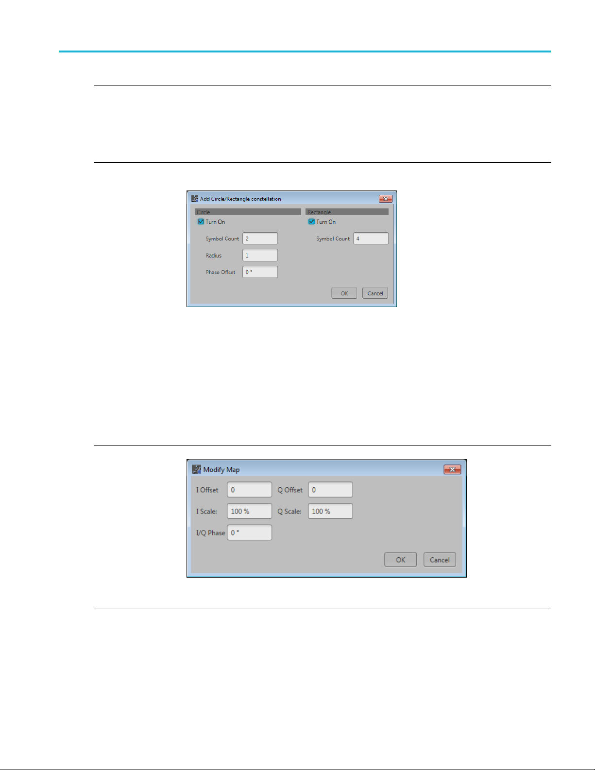
Use the Add Circle/Rectangle constellation dialog box to create a symbol map.
You can crea
Circle
Select Circle to define a constellation w indow that allows you to create equally spaced symbols in
acircleofaspecified radius. You can define an offset angle to rotate the constellation.
Symbol Count: Enter number of symbols (2 to 512) to create the constellation.
Radius: Enter the radius (–5 to 5) of the circle.
Phase Offset: Enter a phase offset (–180° to +180°) to rotate the constellation.
Rectangle
Select Rectangular to define constellation points which are distributed in a rectangular shape,
akin to QA M modulations.
Symbol Count: Enter number of symbols (4 to 512) to create the constellation.
Select Advanced... to display the Modify Map dialog screen.
pdown list of modulation types to pre-populate the symbol table. There are three
lection (of either) adds and additional set of values.
te circular or rectangular constellation (or a combination).
Adjust Offset, Scale, and Phase for I and Q.
e modifications are applied to all Bit Values currently in the Symbol table.
Th
RF Generic Signal Printable Help Document 23
Page 30
Setup tab Custom Modulation setup
Custom Modulat
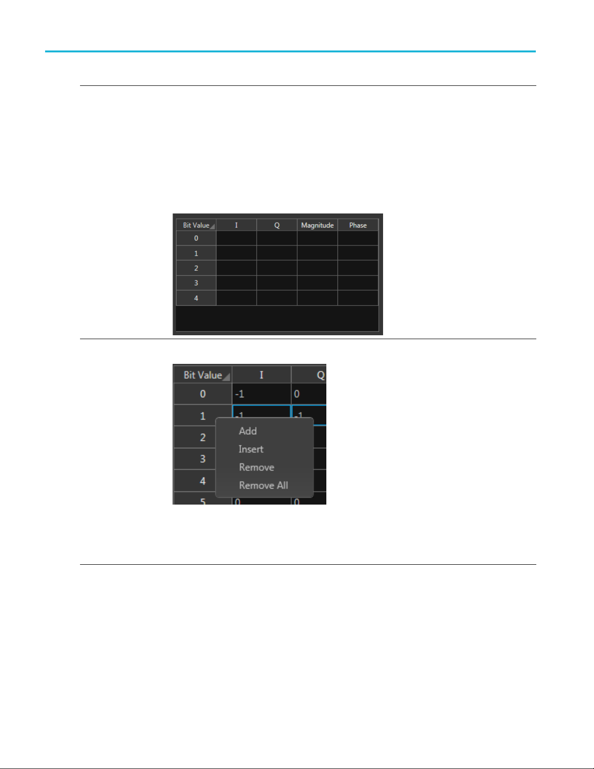
Symbol table e
diting
ion
Use the Symbol
the cell.
I component: Specify the I component of the modulation. Range: –141.421 to 141.421.
Q component : S
Magnitude: Specify the magnitude of the modulation. Range: 0 to 141.421.
Phase: Specify the phase of the modulation. Range: –180° to +180°
The Magnitud
change the value of the I and Q components, the Magnitude and Phase values are recalculated
and updated. Similarly, if you change the Magnitude and Phase values, the values of the I and
Q component
To manage entire rows within the Symbol table, right-click on a row to display the editor menu.
(Select m ultiple rows by holding down the mouse key and sliding to select contiguous rows.)
table to edit the values in a cell. Double-click a cell to enter the edit mode for
pecify the Q component of the modulation. Range: –141.421 to 141.421.
e and Phase parameters depend on the value of the I and Q components. If you
s are recalculated and updated.
Add: Adds a single empty row to the end of the table.
ert: Inserts a single empty row above the currently selected row.
Ins
Remove: Removes the selected rows. (The row m ust be selected from the Bit Value column.)
Remove All: Deletes then entire contents of the table.
24 RF Generic Signal Printable Help Document
Page 31
Setup tab PRBS Editor
Filter
Filter
Window
Convolution Length
xxx
The filter selection is dependent on the Modulation selection.
Select the filt
Gaussian, Triangular, Edge, Half-Sine, and User Defined.
Selecting User Defined provides a filename dialog box to enter a path to a user defined filter
or use the fold
Select the wi
Kaiser, Blackman Harris, Exact Blackman, Flat Top, Tapered Cosine, and Chebyshev Ripple.
Enter the co
The Convolution Length defines the number of adjacent samples to consider while filtering. This in
turn defines the number of filter taps.
er from the following options: Rectangular, Raised Cosine, Root Raised Cosine,
er icon to browse to a filter file.
ndow type from the following: None, Triangular, Hamming, Hanning, Blackman,
nvolution length.
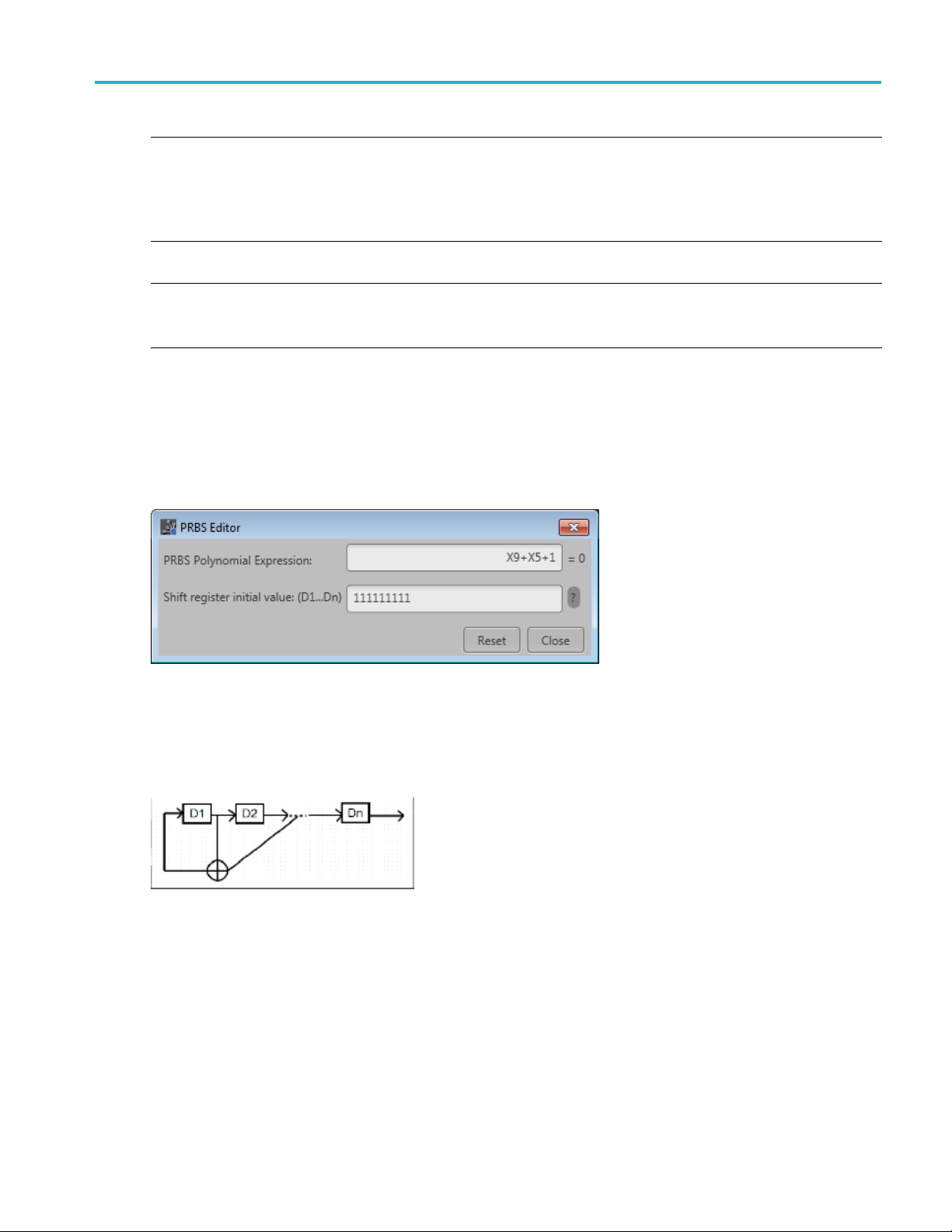
PRBS Edit
This dial
Data field (Setup tab).
PRBS sequences are generated by a feedback shift register. The number (#) following PRBS indicates the
length of the generating shift register. For instance, a shift register with 16 memory cells is required to
generate a PRBS 16 sequence. The pseudo-random sequence of a PRBS generator is determined by the
number of registers and the feedback.
or
og box is displayed when clicking PRBS Editor icon when PRBS is set to User Defined in the
RF Generic Signal Printable Help Document 25
Page 32

Setup tab Modulation types supported
Modulation types supported
Item Description
Digital modul
types
Analog modulation
types
xxx
ation
PSK,
QPSK π/2 QPSK π/4 QPSK π/4 DQPSK OQPSK BPSK π/2 BPSK n DPSK 8 PSK π/2 8 PSK
O-8PSK SDPSK
APSK,
16 APSK, 32 APSK, 64 APSK
QAM,
16 QAM, P/2 16 QAM, 32 QAM, 64 QAM, 128 QAM, 256 QAM, 512 QAM, 1024 QAM
GMSK,
FSK,
2 FSK, 4 FSK, 8 FSK, 16 FSK, 32 FSK
CPM,
{4/16, 5/1
ASK,
OOK.
AM
PM
FM
SBPSK SOQPSK DQPSK
6} {5/16, 6/16} {6/16, 7/16} {7/16, 10/16} {12/16, 13/16} {8/16, 8/16}
26 RF Generic Signal Printable Help Document
Page 33

Hopping Hopping
Hopping
Hopping is only available for use with Digital Modulation and Custom Modulation Carrier Types.
Hopping allows you to add frequency and amplitude hopping for a selected carrier.
Frequency hopping can used to create frequency agile waveforms. Frequency hopping is used in electronic
counter measures by rapidly switching the frequency of the transmitted energy, and receiving only that
frequency during the receiving time window.
Item Description
Hopping Pattern Three hopping patterns are available.
Custom: Hops are based on the Frequency Hop List.
Pseudo Random List: Hops are chosen randomly (based on PRBS selection) from the Frequency
Hop List.
Pseudo Random Range: Hops are chosen randomly (based on PRBS selection) from frequencies
between a minimum and maximum frequency with a minimum frequency spacing Frequencies
included in the Frequency Avoid List will be skipped.
Custom Hopping Pattern
Hop Time
Symbols P er Hop Symbols per Hop determines how many Symbols occur between each Hop. The value applies to
Select the method to define the H op Time
Symbols Per Hop
Hops Per Second
Symbol Start Index
Hop Duration
the entire hop pattern.
Range: 1 to 5000000.
RF Generic Signal Printable Help Document 27
Page 34

Hopping Hopping
Custom Hopping
Hops Per
Second
Pattern
Use the Frequency Hop List
Hops Per Second determines how many hops occur for each second.
Range: 1 to 1000000000.
Use the Frequency Hop List
Symbol Start
Index
Defines the index the s pecifi c hop starts. Each hop must contain a unique start index.
28 RF Generic Signal Printable Help Document
Page 35

Hopping Hopping
Custom Hopp ing
Hop Duration
Pseudo Random List Hopping Pattern
Hop Time
Symbols P er Hop Symbols per Hop determines how many Symbols occur between each Hop. The value applies to
Pattern
Defines the amo
duration.
Select the method to define the H op Time
Symbols Per Hop
Hops Per Second
the entire hop pattern.
Range: 1 to 5000000.
Use the Frequency Hop List
unt of hop time the pattern will play each hop. Each hop must have its own
PRBS Pattern Select the PRBS pattern for hopping.
Pseudo Random Range Hopping Pattern
me
Hop Ti
bols Per Hop
Sym
Minimum Frequency
Maximum Frequency
Frequency Spacing Specify the minimum frequency intervals for hopping. The signal will hop avoiding the frequencies
Select the method to define the H op Time
Symbols Per Hop
Per Second
Hops
bols per Hop determines how many Symbols occur between each Hop. The value applies to
Sym
the entire hop pattern.
Range: 1 to 5000000.
Enter the frequency range within which to hop. Specify the start frequency for the range.
Specify the end frequency for the range.
pecified in the table in this interval or at multiples of this interval.
s
RF Generic Signal Printable Help Document 29
Page 36

Hopping Hopping
Pseudo Random Range Hopping Pattern
PRBS Pattern Select the PRBS pattern for hopping:
Frequency Avoid List
xxx
Enable the Avoid List and the signal will avoid hopping in the frequencies specified in the table.
30 RF Generic Signal Printable Help Document
Page 37

IQ Impairments IQ Impairments
IQ Impairments
IQ Impairments is only available for use with Digital Modulation and Custom Modulation Carrier Types.
Item Descript
Swap I & Q Select t
Leakage
Carrier
Turn on
et
IQ Offs
et
IOffs
QOffset
ear Distortions
Nonlin
Turn on
M
AM/A
AM/PM k2: Enter the 2nd order coefficient for the phase (degrees).
drature Error
Qua
Turn on
QError
I/
Imbalance
IQ
Turn on
Imbalance
xxx
Select t
Adds eq
Adjus
Selec
k2: E
k3: Enter the third order coefficient for the magnitude (dB).
Range: –3 dB to +3 dB.
k3:
Sel
En
Se
E
ion
o interchange I and Q signal outputs.
o add carrier leakage (I and Q) impairments to the carrier.
ual offset to I and Q signals based on the dB value provided.
t the percentage of offset for I and Q based on the IQ Offset dB value.
t to add nonlinear distortions to the carrier.
nter the 2nd order coefficient for the magnitude (dB).
Enter the third order coefficient for the phase (degrees).
ect to add quadrature error to the carrier.
ter the phase angle between the I and Q signals. Range: –30° to +30°.
lect to add IQ imbalance to the carrier.
nter the imbalance between the I and Q signals. Range: –30% to 30% (–2.28 dB to 3.1 dB).
RF Generic Signal Printable Help Document 31
Page 38

IQ Impairments IQ Impairments
32 RF Generic Signal Printable Help Document
Page 39

Power Ramp Power Ramp
Power Ramp
Power ramp allows the user to define the power (amplitude) profile for the signal to be created.
Power Ramp is only available for use with Digital Modulation and Custom Modulation Carrier Types.
Item Descript
Ramp Function
Initial Level
Ramp Duration
Duration Unit
Periodically extend
r levels
powe
xxx
Select t
he level of the power ramping. Range: –100 dB to 0 dB.
Enter t
he duration of ramp. Range: 1 ns to 1 sec.
Enter t
Define
Time: The duration is set in units of time.
Symbols: The duration is set by choosing a start symbol and an end symbol.
The Po
selected, the time characteristic of the power ramping is continued periodically until the
When
end of the signal.
If the total defined Durations of power ramp is less than the waveform duration, the signal power
ing the rest of the duration not defined by the table is set to –200 dB.
dur
If Periodically Extend is selected, the Power ramp table is circularly selected to repeat the pattern
in the table.
ion
he power ramping function from the following: Linear and Cosine.
the duration of time in the defined power level.
wer ramp table adjusts to accommodate using Time or S ymbols.
RF Generic Signal Printable Help Document 33
Page 40

Power Ramp Power Ramp
34 RF Generic Signal Printable Help Document
Page 41

Interference Addition Interference Addition
Interference Addition
The Interference Addition tab has three types of interference to add to the signal:
Sinusoidal Interference
Frequency Offset
Additive Noise
Each interf
Item Description
Sinusoidal
Interference
C / I Enter the carrier-to-interference ratio. Range: –100.00 dB to 100 dB.
Offset from
carrier
Frequency Offset Turn on to include a frequency offset.
Frequency Offset Enter the frequency offset from the carrier frequency.
Additive Noise
Bandwidth
xxx
erence type is independently controlled, allowing to select any combination of interference types
Turn on to include sinusoidal interference for the carrier
Enter the offset from the carrier frequency.
Turn on to simulate additive Gaussian noise by defining the noise in terms of Signal to Noise Ratio
(SNR) or bit Energy per Noise power (Eb/No). You can also define the bandwidth of the noise. A
rectangular filter of bandwidth is applied on the noise signal.
• SNR: Select this to specify the signal to noise ratio. Range: –80.00 dB to 80 dB.
• Eb / No: Select this to specify the energy or Noise power. Range: –80.00 dB to 80 dB.
Enter the bandwidth of the noise to be added.
Range: 1 Hz to the maximum supported by the active instrument.
RF Generic Signal Printable Help Document 35
Page 42

Interference Addition Interference Addition
36 RF Generic Signal Printable Help Document
Page 43
Distortion Distortion
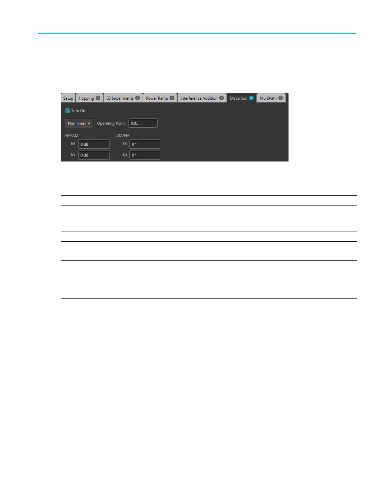
Distortion
Distortion is only available for use with Digital Modulation and Custom Modulation Carrier Types.
Item Descripti
Non linear
Operatin
AM/AM The vari
k3 dB
k5 dB
AM/PM The variation of the phase with respect to the original amplitude is called AM/PM conversion.
k3 dB
k5 dB
Soft Limiting Use Soft limit to limit the signal when the magnitude is beyond the operating point.
Limiting Level
Hard Limiting Use hard limiting to limit the signal when the magnitude is greater than zero.
xxx
g Point
Nonlinea
Enter the
conversion.
Enter the third order coefficient for the magnitude.
Enter the fifth order coefficient for the magnitude.
Enter the third order coefficient for the magnitude.
Enter the fifth order coefficient for the magnitude.
Note that the operating point is normalized to the signal amplitude.
Set a Soft limit level.
on
r Distortions allow you to simulate the nonlinearity of IQ modulators.
operating point of the nonlinear amplifier
ation of the signal amplitude with respect to the original amplitude is called AM/AM
Distortion is only available for use with Digital Modulation and Custom Modulation Carrier Types.
RF Generic Signal Printable Help Document 37
Page 44

Distortion Distortion
38 RF Generic Signal Printable Help Document
Page 45

MultiPath MultiPath
MultiPath
Multipath can be used to simulate the reflected signals which arrive with different delays.
You c a n define a maximum of ten multipaths, setting the delay, amplitude and phase values for each
path. No two paths can have the same delay value.
MultiPath is only available for use with Digital M odulation and Custom Modulation Carrier Types.
Item Description
Delay in
Seconds
ls
Symbo
tude (dB)
Ampli
Phase (deg) Enter the phase in degrees from the reference path. The phase can be positive or negative.
xxx
Enter the delay in seconds or symbols from the reference path. The delay can be positive or
ive. Delay values cannot be repeated.
negat
the amplitude in dB from the reference path. The amplitude for each path can be set to
Enter
zero dB or reduced.
RF Generic Signal Printable Help Document 39
Page 46

MultiPath MultiPath
40 RF Generic Signal Printable Help Document
Page 47

Symbol mapping Symbol mapping
Symbol mapping
The RF Generic Signal plug-in supports many Digital modulation types. Diagrams are available for many
of the more common types to illustrate the Bit mapping of the symbols.
Many of these mapping diagrams are too complex to show within this help system, or from a printed
document. Because of this, the symbol maps are only available by downloading the PDF version of this
help system
The symbol maps are in the form of an external PDF that is attached to the PDF of the help system file.
from the Tektronix web site.
All documentation is available on the Tektronix Web site (www.tek.com/manual/downloads
for the RF Generic Signal User documentation.
). Search
RF Generic Signal Printable Help Document 41
Page 48

Symbol mapping Symbol mapping
42 RF Generic Signal Printable Help Document
Page 49

Sub Carrier Modulation tab Sub Carrier Modulation tab
Sub Carrier Modulation tab
Enable Sub Carrier Modulation to modulate the signal setup in the Carries table. The sub-carrier
modulation affects all Carriers.
Sub carrier modulation is only available for RF/IF Signal Formats.
Item Description
Carrier Frequency Enter the sub-carrier frequency. The range is instrument dependent.
Modulation
xxx
Select the sub-carrier modulation type.
■ AM modulation displays the AM index control (modulation depth) to set the percentage of
how much carrier amplitude varies from the unmodulated level.
■ PM modulation displays the Phase Deviation control to set the maximum difference
between the instantaneous phase angle of the modulated wave and the phase angle of the
unmodulated carrier.
■ FM modulation displays the Frequency Deviation control to set the maximum difference
between the FM modulated frequency and the carrier frequency.
RF Generic Signal Printable Help Document 43
Page 50

Sub Carrier Modulation tab Sub Carrier Modulation tab
44 RF Generic Signal Printable Help Document
Page 51

S-Parameter tab S-Parameter license
S-Parameter license
A license is required to use the S-Parameter feature.
S-Parameters is available when a license is detected by the application. With the license installed on the
host PC where SourceXpress is installed, S-Parameters is available regardless of connecting to a virtual
generator or a real instrument.
Refer to Licensing
S-Parameter tab
Enable S-Parameters to apply scattering parameters to the waveform.
S-Parameters can be applied to the RF/IF waveform or to the I and Q data, depending on the selected
Signal Format.
All S-Parameter features apply whether the Signal Format is set to RF/IF or IQ. The only exception is that
an additional control is available for the IQ signal format to choose how the S-Parameters are applied
to the I and Q components.
For the IQ Signal Format, select to apply unique
ameters to the individual I and Q components
S-Par
or apply the same S-Parameters to both I and Q.
For instance, to apply unique parameters to I and Q, select I and set the parameters. Then select Q and set it’s parameters.
The application retains the settings for both I and Q.
If you select Couple Settings, the parameters you set are applied to both I and Q.
(see page 51) for information about obtaining a license file.
CAUTION. When selecting Couple Settings (I,Q), the Q parameters are instantly replaced with the I parameters.
xxx
Below is a sample S-Parameter dialog screen with the Number of Ports set to 4. The dialog screen changes
to accommodate the Number of Ports selected.
The information provided for S-Parameters applies to both the Non-Cascading and Cascading modes.
RF Generic Signal Printable Help Document 45
Page 52

S-Parameter tab S-Parameter tab
46 RF Generic Signal Printable Help Document
Page 53
S-Parameter tab S-Parameter tab
Item Description
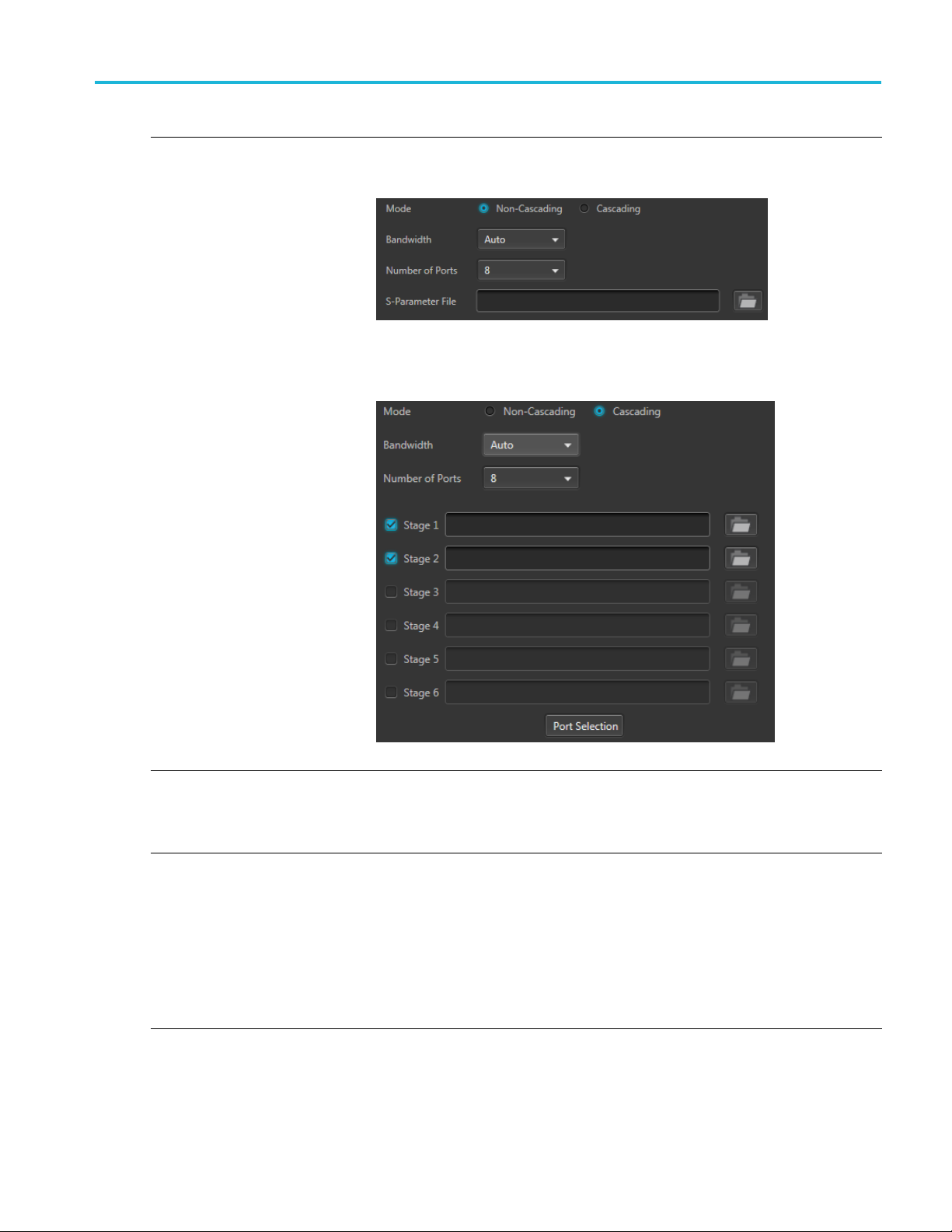
Mode
Select Non-Cascading or Cascading S-parameter mode.
In the Non-Cas
from only one S-parameter file.
In the Cascading mode, you can cascade up to six S-parameter files in Stages and
apply the characteristics on the signal. You can select the files to apply by turning on
or turning off the corresponding Stages shown in the display. All the selected files
should be of the same type. The settings depend on the selected type of file.
cading mode, you apply S-parameter characteristics on the signal
The files supported are s1p, s2p, s4p, s6p, s8p, and s12p.
De-embed
(Non-Cascading mode)
Cascading De-embed
(Cascading mode)
Bandwidth
Check the box to invert the S-Parameters from the signal. This removes the effects
of the component (for which the S-Parameters were created) from the signal path.
Auto – The bandwidth is defined at the point where the signal rolls off to -60 dB. If
this results in a bandwidth greater than the instrument supports, the bandwidth is set
to ½ of the waveform’s sample rate (i.e. Nyquist Frequency).
Full Bandwidth – The bandwidth is set to ½ of the waveform’s sample rate (i.e.
Nyquist Frequency).
Manual – The bandwidth can set by the user from 1 Hz to ½ of the maximum sample
rate of the instrument. If the set Bandwidth is greater than the Nyquist (Sample rate
of the waveform/2), then the software limits the bandwidth to ½ of the waveform’s
sample rate. A warning message is provided.
RF Generic Signal Printable Help Document 47
Page 54
S-Parameter tab S-Parameter tab
Item Description
Number of Ports Choose the number of ports. The port matrixes supported are 1, 2, 4, 6, 8, and 12.
The number of p
• The type of S-Parameter file to apply
• The Signaling Scheme choice
• The port mat
S-Parameter
Signaling
(Only for 4, 8, and 12 ports)
Selection of the port
(No port s
environments)
Victim
Aggress
(Only for 8 and 12 ports)
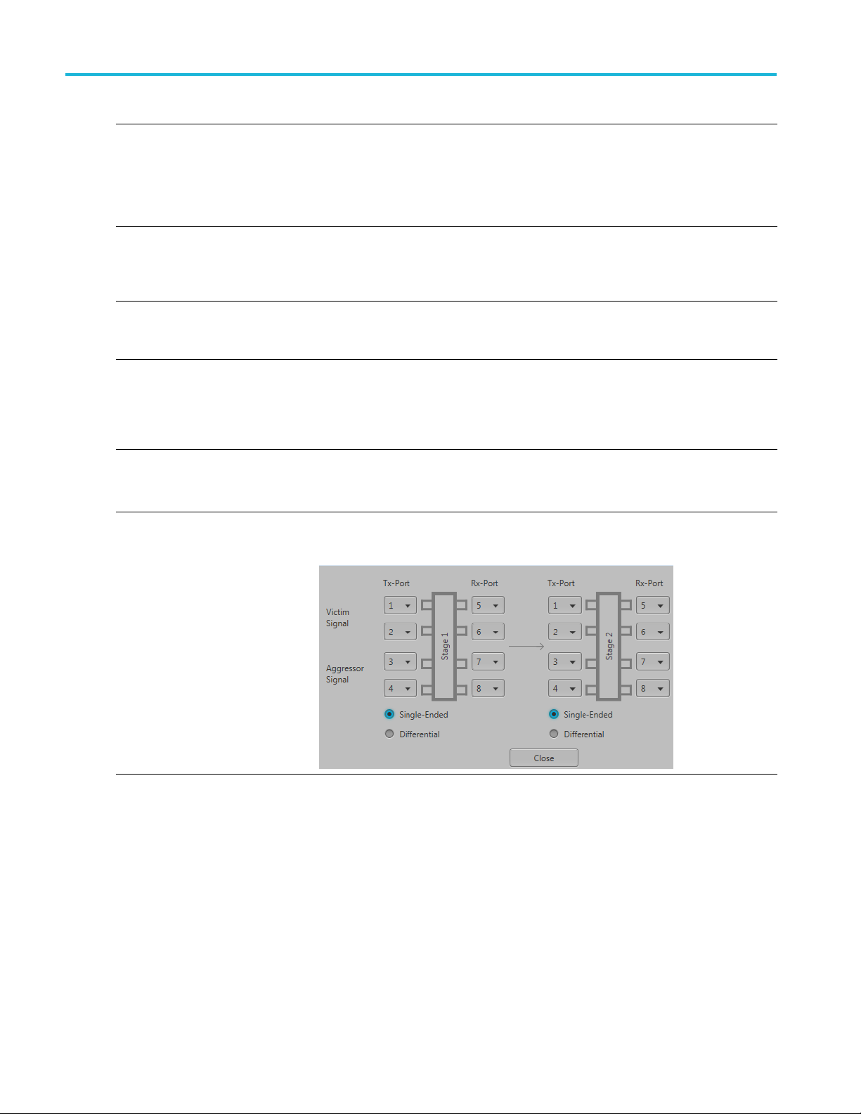
Port Selection The Port Selection button is available only when in Cascading mode. Press the
File
Scheme
election for 1 Port
or and Both
Navigate to t
that you are able to open is dependent on the number of ports selected. For instance,
only .s4p files can be opened if the Number of Ports is set to 4.
The files sup
Single-En
the file to physical locations in your link.
Differential: If the data is differential, you must select the data layout in the file.
Use the diagrams to m ap the ports for the transmitter ports (Tx-Port) and the receiver
ports (Rx
When choosing the number of Ports, you are presented with an active diagram of
the ports. The diagram presented reflects the Number of Ports selected and the
ing Scheme (if appropriate for the ports selected).
Signall
The default setting with no cross-talk effects.
Victim:
Aggressor: Select this to activate aggressor signal parameters, adding the effect
of cross-talk.
Port Selection button to display an active dialog screen to map the ports for the
itter ports (Tx-Port) and the receiver ports (Rx-Port) for each stage.
transm
orts selected determines:
rixes available
he Touchstone file to apply to the signal. The type of Touchstone files
ported are s1p, s2p, s4p, s6p, s8p, and s12p.
ded: If the data is single-ended, you must map the port numbers as used in
-Port).
xxx
S-Parameter file descriptions
1-port
Files with one port of data contain only one S-parameter file (s1p) so they do not require any further input.
48 RF Generic Signal Printable Help Document
Page 55

S-Parameter tab S-Parameter tab
2-port
Files with data for two ports contain four S-parameters as a 2x2 matrix. These are Touchstone 2-port files
p). A dialog box is created to define the 2-port mapping.
(s2
4-Port
Files with data for four ports contain 16 S-parameters as a 4x4 matrix. These are Touchstone 4-port files
(s4p). They may contain single-ended or differential data. A dialog box is created to define the 4-port
mapping for either single-ended or differential data.
If the data is single-ended, you must map the port numbers as used in the file to physical locations in
your link.
You can select the port for both transmitter and receiver from the drop-down list. Each drop-down list
has ports from 1 to 2.
If the data is differential, you must select the data layout in the file.
6-port
Files with data for six ports contain 36 S-parameters as a 6x6 matrix. These are Touchstone 6-port files
(s6p). A dialog box is created to define the 6-port mapping.
8-Port
Files with data for eight ports contain 64 S-parameters as an 8x8 matrix. These are Touchstone 8-port files
(s8p). They may contain single-ended or differential data. A dialog box is created to define the 8-port
mapping for either single-ended or differential data.
If the data is single-ended, you must map the port numbers as used in the file to physical locations in
your link.
You can select the port for both transmitter and receiver from the drop-down list. Each drop-down list
has ports from 1 to 4.
If the data is differential, you must select the data layout in the file.
12-Port
Files with data for 12 ports contain 144 S-parameters as an 12x12 matrix. These are Touchstone 12-port
files (s12p). They may contain s ingle-ended or differential data. A dialog box is created to define the
12-port mapping for either single-ended or differential data.
If the data is single-ended, you must map the port numbers as used in the file to physical locations in
your link.
You can select the port for both transmitter and receiver from the drop-down list. Each drop-down list
has ports from 1 to 6.
If the data is differential, you must select the data layout in the file.
RF Generic Signal Printable Help Document 49
Page 56

S-Parameter tab S-Parameter tab
Aggressor signals
8 and 12 port S-parameters allows you to activate aggressor signal parameters and to add the effect of
cross-talk. 12 port S-parameters allows 2 Aggressor signal parameters.
AggressorscanbeaddedineitherNon-Cascading Mode or Cascading Mode.
The Aggresso
Item Description
Signal Choose the type of aggressor signal with the dropdown list:
Data Rate
Aggressor Amplitude Enter the signal amplitude.
Crosstalk Type Choose the type of crosstalk of the aggressor signal.
xxx
r signal parameters include:
•Clock: Ind
• PBRS: Also choose the number of bits
• File: Indicates that the aggressor signal is another pattern file. Navigate to
the Patter
• Same as victim: The signal flow of the aggressor is same as the victim.
Specify the data rate (in bps) of the signal.
This is not available when the Aggressor signal is set to be the same as the victim.
This is not available when the Aggressor signal is set to be the same as the victim.
• Near-
• Far-End Crosstalk
• Both
icates that the aggressor signal is a clock pattern.
n file
End Crosstalk
50 RF Generic Signal Printable Help Document
Page 57

Licensing Licensing
Licensing
A license is required for this plug-in to become operational. The plug-in must be licensed for use with the
host application from where you want to use the plug-in.
For example, to use the plug-in from SourceXpress, SourceXpress must have a license. To use the plug-in
from an instrument, the instrument must have a license.
Refer to the application help (such as SourceXpress or the host instrument) for information about obtaining
and installing license files.
RF Generic Signal Printable Help Document 51
Page 58

Licensing Licensing
52 RF Generic Signal Printable Help Document
Page 59

Index
Index
A
Aggressor, 50
Analog Modul
Apply correction file, 9
ation setup, 21
C
Carrier list, 13
add carrier, 14
add multiple carrier, 14
menu operations, 13
Channel t
Compile, 6
Compile settings, 7
Correction file, 9
Custo
Custom Modulation setup, 22
ab
S-Parameters, 45
frequency response, 10
m hopping pattern, 27
D
Digital Modulation setup, 18
Display elements, 5
Distortion, 37
Documentation, 3
nected instrument, 3
Con
RF Generic plug-in, 3
SourceXpress, 3
E
Elements of the display, 5
H
Help menu, 12
Hopping, 27
Hopping pattern
custom, 27
Pseudo Random List, 29
Pseudo Random Range, 29
I
Interference Addition, 35
IQ
compile settings, 7
IQ Impairm
carrier leakage, 31
IQ imbalance, 31
nonlinear distortions, 31
quadrature error, 31
IQ modulator, 8
ents, 31
K
Key fea
tures, 2
L
Licensing, 51
M
Modulation
sub carrier, 43
symbol mapping, 41
Modulation types
ported, 26
sup
Modulator
IQ, 8
MultiPath, 39
Multitone plug-in
description, 1
N
Noise setup, 22
P
Plug-in selection, 5
Power Ramp, 33
PRBS Editor, 25
Pseudo Random List hopping
pattern, 29
Pseudo Rand
pattern, 29
om Range hopping
R
Reset Plug-in, 12
RF/IF
compile settings, 7
S
S-Parameter
file typ
S-Parameter license, 45
S-Parameters, 45
Aggressor, 48
Cascading, 47
De-embed, 47
Diff
Non-Cascading, 47
Number of Ports, 48
Selection of the port, 48
Signalling Scheme, 48
Single-Ended, 48
Vi
Service support, 3
Setup, 17
Signal format selection, 6
Sub carrier modulation, 43
Support information, 3
Symbol mapping, 41
es, 48
erential, 48
ctim, 48
T
Technical support, 3
RF Generic Signal Printable Help Document 53
 Loading...