

Page 1

User Manual
RFA300A
Measurement Set 8VSB
071-0697-01
www.tektronix.com
Page 2

Copyright © Tektronix, Inc. All rights reserved.
Tektronix products are covered by U.S. and foreign patents, issued and pending. Information in this publication supercedes
that in all previously published material. Specifications a nd pric e change privileges reserved.
Tektronix, Inc., P.O. Box 500, Beaverton, OR 97077
TEKTRONIX and TEK are registered trademarks of Tektronix, Inc.
Page 3

WARRANTY
Tektronix warrants that the products that it manufactures and sells will be free from defects in materials and
workmanship for a period of one (1) year from the date of shipment. If a product proves defec tive during this
warranty period, Tektronix, at its option, either will re pair the defective product without charge for parts and labor,
or will provide a replacement in exchange for the defective product.
In order to obtain service under this warranty, Customer must notify Tektronix of the defect before the expiration
of the warranty period and make suita ble arrangements for the performance of service. Customer shall be
responsible for packaging and shipping the defective product to the service center designated by Tektronix, with
shipping charges prepaid. Tektronix shall pay for the return of the product to Customer if the shipment is to a
location within the country in which the Tektronix service center is located. Customer shall be responsible for
paying all shipping charges, duties, taxes, and any othe r charges for products returned to any other locations.
This warranty shall not apply to any defect, failure or damage caused by improper use or improper or inadequate
maintenance and care. Tektronix shall not be obligated to furnish service under this warranty a) to repair damage
resulting from attempts by personnel other than Tektronix re presentatives to install, repair or service the product;
b) to repair damage resulting from improper use or connection to incompatible equipment; c) to repair any
damage or malfunction caused by the use of non-Tektronix supplies; or d) to service a product that has been
modified or integrated with other products when the effect of such modification or i ntegration increases the time
or difficul ty of servicing the product.
THIS WARRANTY IS GIVEN BY TEKTRONIX IN LIEU OF ANY OTHER WARRANTIES, EXPRESS
OR IMPLIED. TEKTRONIX AND ITS VENDORS DISCLAIM ANY IMPLIED WARRANTIES OF
MERCHANTABILITY OR FITNESS FOR A PARTICULAR PURPOSE. TEKTRONIX’
RESPONSIBILITY TO REPAIR OR REPLACE DEFECTIVE PRODUCTS IS THE SOLE AND
EXCLUSIVE REMEDY PROVIDED TO THE CUSTOMER FOR BREACH OF THIS W ARRANTY.
TEKTRONIX AND ITS VENDORS WILL NOT BE LIABLE FOR ANY INDIRECT, SPECIAL,
INCIDENTAL, OR CONSEQUENTIAL DAMAGES IRRESPECTIVE OF WHETHER TEKTRONIX OR
THE VENDOR HAS ADVANCE NOTICE OF THE POSSIBILITY OF SUCH DAMAGES.
Page 4

Page 5

Table of Contents
Getting Started
General Safety Summary vii.........................................
Preface ix........................................................
Related Documentation ix...........................................
Contacting Tektronix x.............................................
Getting Started 1--1............................................
Product Description 1--1..............................................
Accessories 1--4.....................................................
Installation 1--5...............................................
Check the Shipping List 1--5...........................................
Operating Requirements 1--6...........................................
Hardware Installation 1--6.............................................
Creating a Startup Disk 1--13...........................................
RF Connections 1--14.................................................
Interface Connections 1--16.............................................
Keyboard and Mouse Connections 1--16...................................
Powering On and Off 1--17.............................................
Selecting RF Input Channel and Channel Freque ncy 1--18....................
Incoming Inspection 1--20..............................................
Operating Basics
Reference
Operating Basics 2--1..........................................
Front Panel 2--1.....................................................
Home Window 2--4..................................................
Making a Measurement 2--6...........................................
Online Help 2--9.....................................................
Backing Up Files 2--10................................................
RFA300A Reference 3--1........................................
Out of Channel Emissions 3--1.........................................
S/N, EVM, and Pilot Amplitude Error 3--3................................
Phase Noise 3--4.....................................................
Frequency Response and Group Delay 3--6...............................
Amplitude and Phase Errors 3--8........................................
Peak-to-Average and Channel Spectrum 3--10..............................
Signal Monitor 3--12..................................................
8VSB Overview 3--14.................................................
Closed-Loop Transmitter Control 3--18...................................
RFA300A Measurement Set 8VSB
i
Page 6

Table of Contents
Appendices
Appendix A: Specifications A--1..................................
Specification Tables A--1..............................................
Performance Conditions A--1...........................................
RFA300A Measurement Set Specifications A--2............................
Measurement Specifications A--4........................................
Platform Characteristics A--9...........................................
Power Characteristics A-- 13.............................................
Environmental Characteristics A--14......................................
Electromagnetic Compatibility A--16.....................................
Mechanical (Physical) Characteristics A--18................................
Appendix B: User Service B--1...................................
General Care B--1....................................................
Preventive Maintenance B --1...........................................
In Case of Problems B--3..............................................
Repackaging for Shipment B--5.........................................
Appendix C: System Recovery C--1...............................
Overview C--1.......................................................
Restore the BIOS Settings C--3.........................................
Restore the Contents of the Partitions C--4................................
Install and Configure Individual Components C--6..........................
Appendix D: Mask File Formatting D--1...........................
Glossary
Index
ii
RFA300A Measurement Set 8VSB
Page 7

List of Figures
Table of Contents
Figure 1--1: RFA300A 8VSB Measurement Set front panel 1--2.......
Figure 1--2: Home window 1--3..................................
Figure 1--3: Attaching the extension brackets to the
stationary tracks 1 --8.......................................
Figure 1--4: Mounting hole selection on the front rails of the
equipment rack 1--8........................................
Figure 1--5: Attaching the extension bracket to the rear rail of the
equipment rack 1--9........................................
Figure 1--6: Mounting the stationary section to the front rail of the
equipment rack 1--10........................................
Figure 1--7: Stationary bracket, extension bracket, and
attaching screws 1--10........................................
Figure 1--8: Installing the instrument into the equipment rack 1--11....
Figure 1--9: Transmitter connection 1--14...........................
Figure 1--10: Rear view 1--15.....................................
Figure 1--11: Keyboard and mouse connections 1--16.................
Figure 1--12: On/Standby switch 1--17.............................
Figure 1--13: System setup 1-- 19..................................
Figure 2--1: Front panel 2--1.....................................
Figure 2--2: Home window 2--4..................................
Figure 2--3: Toolbar 2--5........................................
Figure 2--4: Help menu 2--9.....................................
Figure 3--1: Out of Channel Emissions measurement window 3--2.....
Figure 3--2: Out of Channel Emissions setup 3--2...................
Figure 3--3: S/N, EVM, and Pilot Amplitude measurement window 3--3
Figure 3--4: Phase Noise Measurement window 3--5.................
Figure 3--5: Phase Noise setup 3--5...............................
Figure 3--6: Frequency Response and Group Delay measurement
window 3--7...............................................
Figure 3--7: Frequency Response and Group Delay setup 3--7.........
Figure 3--8: Amplitude and Phase Errors measurement window 3--9...
Figure 3--9: Amplitude Error and Phase Error setup 3--9............
Figure 3--10: Peak-to-Average and Channel Spectrum measurement
window 3--10...............................................
RFA300A Measurement Set 8VSB
iii
Page 8

Table of Contents
Figure 3--11: Peak-to-Average Setup 3--11..........................
Figure 3--12: Signal Monitor measurement window 3--12.............
Figure 3--13: Signal Monitor Setup 3--13...........................
Figure 3--14: 8VSB exciter block diagram 3--14......................
Figure 3--15: Data interleaving 3--15...............................
Figure 3--16: Data segment sync 3--16..............................
Figure 3--17: Frame synchronizing segment 3--17....................
Figure A--1: IF filter characteristics A--3...........................
Figure A--2: 8VSB transmitter emissions mask A--8.................
Figure B--1: Repackaging the instrument (new packagin g) B--6.......
Figure B--2: Repackaging the instrument (old p ackaging) B--8........
Figure B--3: Placement of bottom spacer pad in inner shipping box B--9
iv
RFA300A Measurement Set 8VSB
Page 9

List of Tables
Table of Contents
T able 1--1: Standard accessories 1--4.............................
Table 1--2: Optional accessories 1--4..............................
Table 1--3: Operating requirements 1--6..........................
Table 2--1: Front panel-key controls 2--2..........................
Table 2--2: Control key combination functions 2--3.................
Table 2--3: Toolbar functions 2--5................................
Table A--1: Input specifications A--2..............................
T able A--2: Measurement specifications A--4.......................
T able A--3: System components A--9..............................
T able A--4: Front panel interface characteristics A--10................
Table A--5: Rear panel interface characteristics A--11................
T able A--6: AC power source characteristics A--13...................
T able A--7: Environmental characteristics A--14.....................
Table A--8: Dynamics A--15......................................
Table A--9: Transportation A--15..................................
Table A--10: Certifications and compliances A--16...................
T able A--11: Mechanical characteristics A--18.......................
Table B--1: Troubleshooting B--4.................................
Table D--1: ResultID Values for Mask Tests D--2....................
RFA300A Measurement Set 8VSB
v
Page 10

Table of Contents
vi
RFA300A Measurement Set 8VSB
Page 11

General Safety Summary
Review the following safety precautions to avoid injury and prevent damage to
this product or any products connected to it. To avoid potential hazards, use this
product only as specified.
Only qualified personnel should perform service procedures.
ToAvoidFireor
Personal Injury
Use Proper Power Cord. Use only the power cord specified for this product and
certified for the country of use.
Ground the Product. This product is grounded through the grounding conductor
of the power cord. To avoid electric shock, the grounding conductor must be
connected to earth ground. Before making connections to the input or output
terminals of the product, ensure that the product is properly grounded.
Observe All Terminal Ratings. To avoid fire or shock hazard, observe all ratings
and markings on the product. Consult the product manual for further ratings
information before making connections to the product.
Do Not Operate Without Covers. Do not operate this product with covers or panels
removed.
Use Proper Fuse. Use only the fuse type and rating specified for this product.
Avoid Exposed Circuitry. Do not touch exposed connections and components
when power is present.
Do Not Operate With Suspected Failures. If you suspect there is damage to this
product, have it inspected by qualified service personnel.
Do Not Operate in Wet/Damp Conditions.
Do Not Operate in an Explosive Atmosphere.
Keep Product Surfaces Clean and Dry.
Provide Proper Ventilation. Refer to the manual’s installation instructions for
details on installing the product so it has proper ventilation.
RFA300A Measurement Set 8VSB
vii
Page 12
General Safety Summary
Symbols and Terms
Terms in this Manual. These terms may appear in this manual:
WARNING. Warning statements identify conditions or practices that could result
in injury or loss of life.
CAUTION. Caution statements identify conditions or practices that could result in
damage to this product or other property.
Terms on the Product. These terms may appear on the product:
DANGER indicates an injury hazard immediately accessible as you read the
marking.
WARNING indicates an injury hazard not immediately accessible as you read the
marking.
CAUTION indicates a hazard to property including the product.
Symbols on the Product. The following symbols may appear on the product:
CAUTION
Refer to Manual
Protective Ground
(Earth) Terminal
viii
RFA300A Measurement Set 8VSB
Page 13

Preface
This manual contains operating information for the RFA300A Measurement Set
8VSB. The manual consists of the following sections:
H Chapter 1: Getting Started. Provides a product description, installation
procedures, connection information, and information on getting the
instrument ready for use.
H Chapter 2: Operating Basics. Provides basic information about using the
instrument.
H Chapter 3: Reference. Contains an overview of each measurement window
and of the 8VSB standard.
H Appendix A: Specifications. Lists the environmental, physical, and electrical
properties of the instrument.
H Appendix B: User Service. Provides user service information including
general care, preventive maintenance, troubleshooting, and repackaging.
H Appendix C: Software Installation. Describes how to format a hard drive and
reinstall the operating system software and associated hardware drivers.
Related Documentation
H Appendix D: Mask File Formatting. Describes how to format a mask file
using a text editor.
In addition to this user manual, the following documentation is available for your
measurement set.
H The online help provides information about using the measurement set. To
view online help, select Help Topics from the Help menu.
H The optional RFA300A Measurement Set 8VSB Service Manual provides
board-level service information.
RFA300A Measurement Set 8VSB
ix
Page 14

Preface
Contacting Tektronix
Phone 1-800-833-9200*
Address Tektronix, Inc.
Department or name (if known)
14200 SW Karl Braun Dri ve
P.O. Box 500
Beaverton, OR 97077
USA
Web site www.tektronix.com
Sales support 1-800-833-9200, select option 1*
Service support 1-800-833-9200, select option 2*
Technical support Email: techsupport@tektronix.com
1-800-833-9200, select option 3*
6:00 a.m. -- 5:00 p.m. Pacific time
* This phone number is toll free in North America. After office hours, please leave a
voice mail message.
Outside North America, contact a Tektronix sales office or distributor; see the
Tektronix web site for a list of offices.
x
RFA300A Measurement Set 8VSB
Page 15

Getting Started
Product Description
This chapter provides basic information about using and installing the RFA300A
Measurement Set 8VSB. There is information about the physical instrument and
introductory material on how to operate it. Once you have a basic understanding,
proceed to the next chapter, Operating Basics, to form a conceptual model of
how the measurement set works.
The measurement set provides information on 8VSB digital television signals in
conformance with the ATSC Digital Television Standard. Signals are acquired at
the transmitter and the measurements consist of the following:
H Complex Modulation Error Ratio
H Signal to Noise Ratio
H Error Vector Magnitude
H Pilot Amplitude Error
H Out-of-Channel Emissions
H Frequency Response Error
H Group Delay
H Amplitude Error
H Phase Error
H Phase Noise Error
H Peak to Average Ratio
H Channel Spectrum (display of the selected channel, not a measurement)
The instrument’s measurements can run continuously, thereby monitoring
transmitter performance on a constant basis. Operation of the instrument is
controlled from the front panel keypad and the touch screen or from an attached
keyboard and mouse. Figure 1--1 shows the front panel of the measurement set.
RFA300A Measurement Set 8VSB
1- 1
Page 16
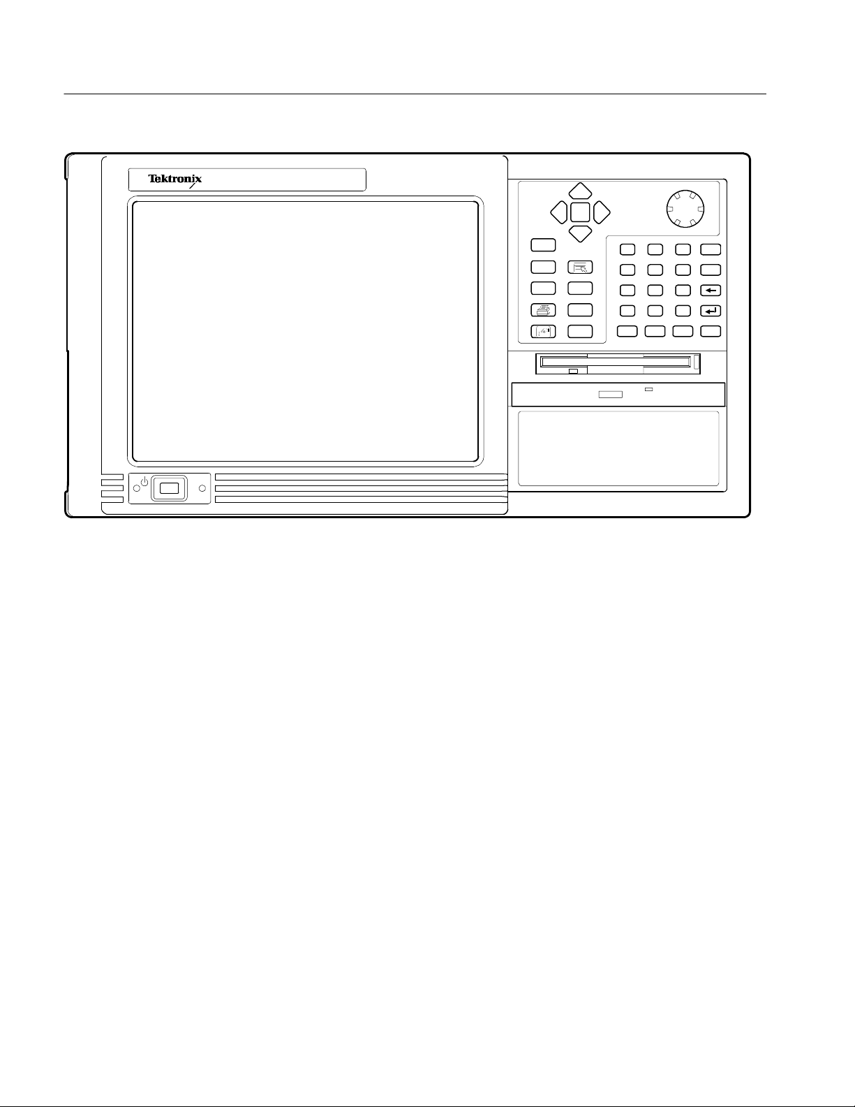
Getting Started
Figure 1- 1: RFA300A 8VSB Measurement Set front panel
The measurement set uses the Microsoft Windows NT operating system. The
Home window is the point-of-entry into the program. Access each measurement
from the Home window by clicking on the appropriate icon as shown in
Figure 1--2 on page 1--3.
1- 2
RFA300A Measurement Set 8VSB
Page 17
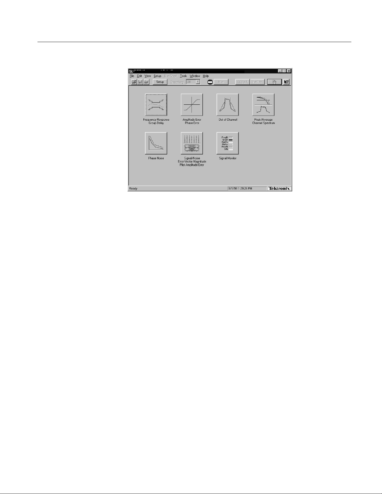
RFA300A --Home
Figure 1- 2: Home window
Getting Started
Refer to the next chapters Operating Basics and Reference for an overview on
operating the measurement set. For detail information, refer to the online help.
RFA300A Measurement Set 8VSB
1- 3
Page 18
Getting Started
Accessories
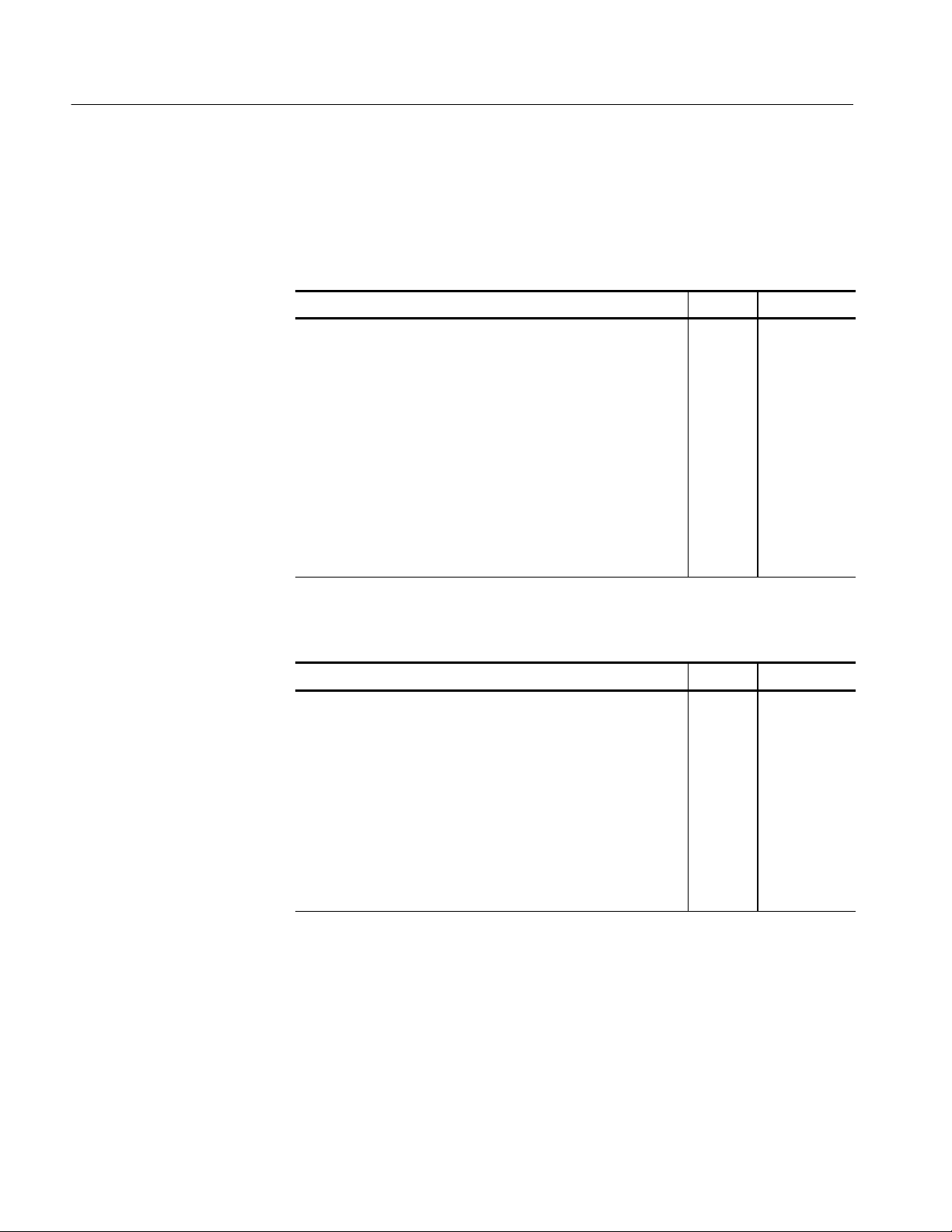
Table 1--1 and Table 1--2 list the standard and optional accessories.
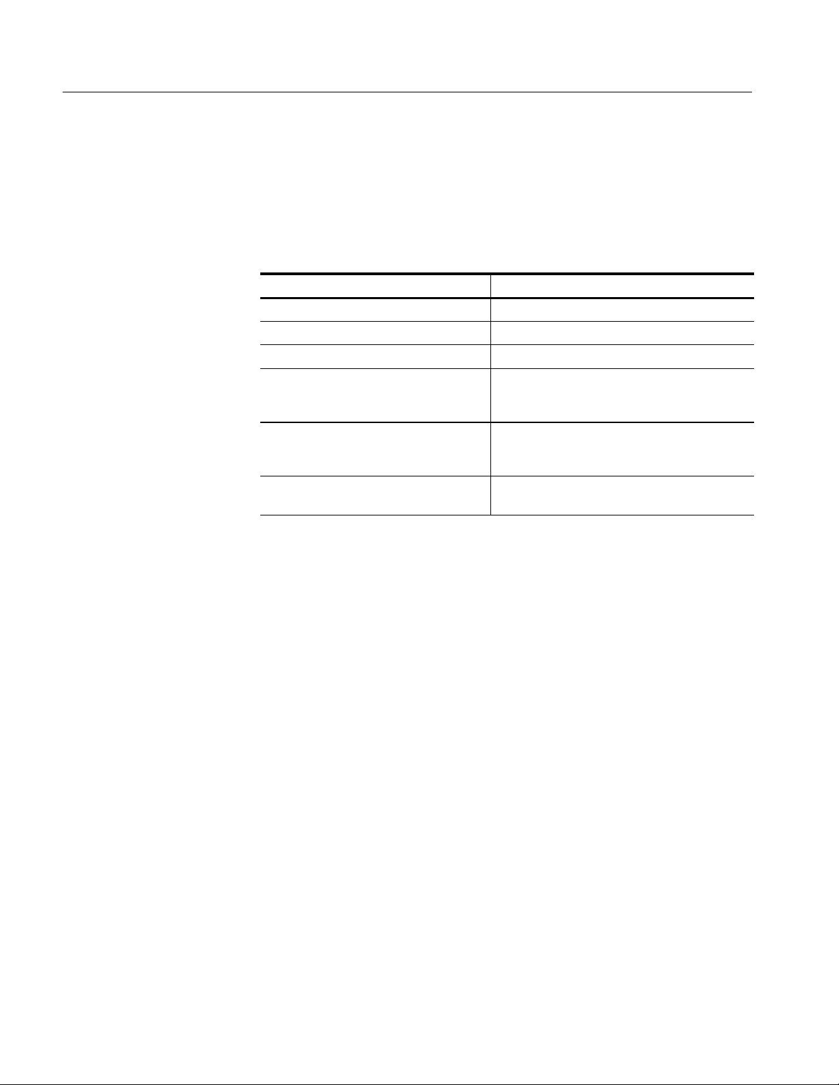
Table 1- 1: Standard accessories
Description Quantity Part number
RFA300A Measurement Set 8VSB User Manual 1 071-0697-XX
RFA300A Measurement Set 8VSB Application Software on
CD-ROM
Windows NT Software and manual on CD-ROM 1 119-5514-XX
WINNT keyboard (US) 1 119-6216-XX
Tektronix three-button mouse 1 119-4330-XX
Standard IEC power cord, 125 V 1 161-0104-00
Front protective cover 1 200-4408-XX
10 dB Attenuator 1 119-6328-00
Rackmount slides hardware kit 1 -- -- -- -- -- -- -- -- --
1 063-3410-XX
Table 1- 2: Optional accessories
Description Quantity Part number
Accessory pouch 1 016-1441-XX
Power cord options
Opt. A1 Universal Euro 230 V, 50 Hz 1 161-0104-06
Opt. A4 North America 240 V, 60 Hz 1 161-0104-08
1- 4
Portable cabinet kit w/ instructions 1 016-1929-XX
Option D1, Calibration certificate 1 -- -- -- -- -- -- -- -- --
RFA300A Measurement Set 8VSB Service Manual
with
Performance Procedure and Adjustment Procedure software disk
1
1
071-0698-XX
063-3411-XX
RFA300A Measurement Set 8VSB
Page 19

Installation
Check the Shipping List
Read this section before attempting any installation procedures. This section
describes site considerations, power requirements, and ground connections for
your instrument.
Verify that you have received all of the parts of your measurement set. Use the
shipping lists that came with your instrument to compare against the actual
contents of your order. You should also do the following:
H Verify that you have the correct power cord for your geographical area.
H Verify that you have the CD that contains a backup copy of the installed
software. Store the CD in a safe location where you can easily retrieve the
software for maintenance purposes.
H Verify that you have a boot disk in case you reformat the hard drive or
damage operating system files or drivers.
NOTE. Keep the software packaging available. You will need it to enter the
Windows NT software registration number when you first power on the analyzer.
(See step 3 under Powering On and Off on page 1--18.)
H Verify that you have all the other standard and optional accessories that you
ordered.
RFA300A Measurement Set 8VSB
1- 5
Page 20
Installation
Operating Requirements
Table 1--3 lists the operating requirements. Refer to Appendix A: Specifications
for a complete specification list.
Table 1- 3: Operating requirem ents
Requirement Specification
Source voltage 90--250 VAC
Steady State input current 6A
Maximum power consumption 540W
Temperature +5 °Cto+45°C(32°Fto113°F), 30 °C/hr max
Humidity 20% to 80% relative humidity, non-condensing.
maximum, 1.9 A typical
RMS
gradient, non-condensing (derated 1 °C per
1,000 ft. above 5,000 ft. altitude)
Max wet bulb temperature: +31 °C (derates
relative humidity to ~50% @ 50 °C).
,47--63Hz
RMS
Hardware Installation
Altitude To 10,000 ft. (3,040 m), (derated 1 °C per
1,000 ft. above 5,000 ft. altitude).
Before you can operate the product, you must connect the provided power cord.
Refer to Figure 1--10 and connect the power cord to the instrument. Refer to
Table 1--3 for the supply voltage rating and connect the other end of the power
cord to the proper source. Do not connect to any power sources other than those
for which the instrument is rated.
This section deals with hardware installation. To reinstall software, refer to
Appendix C: System Recovery.
The factory installed cabinet is designed to operate in an equipment rack (see
Rackmount Installation on page 1--7). The optional portable cabinet allows you
to operate the instrument on a bench or cart (see Portable Installation on
page 1--12). For proper cooling, at least two inches (5.1 cm) of clearance is
recommended on the rear and sides of the instrument cabinet.
The measurement set is limited to installations where a single, high-amplitude,
8VSB RF signal is available for direct input to the measurement set. Refer to RF
Connections on page 1--14.
1- 6
RFA300A Measurement Set 8VSB
Page 21
Installation
Rackmount Installation
If your instrument has the rackmount cabinet, there is rackmounting hardware on
each side of the cabinet.
CAUTION. For proper cooling in an equipment rack installation, the air
temperature at all air intake vents (inside of the rack) must not exceed 50
Mounting the Stationary Tracks in the Equipment Rack. The slider kit consists of
left and right stationary tracks that must be installed in the equipment rack. Extra
hardware is provided with the slider assemblies. Since the hardware is intended
to make the sliders compatible with a variety of racks and installation methods,
not all of the hardware will be used for any installation procedure.
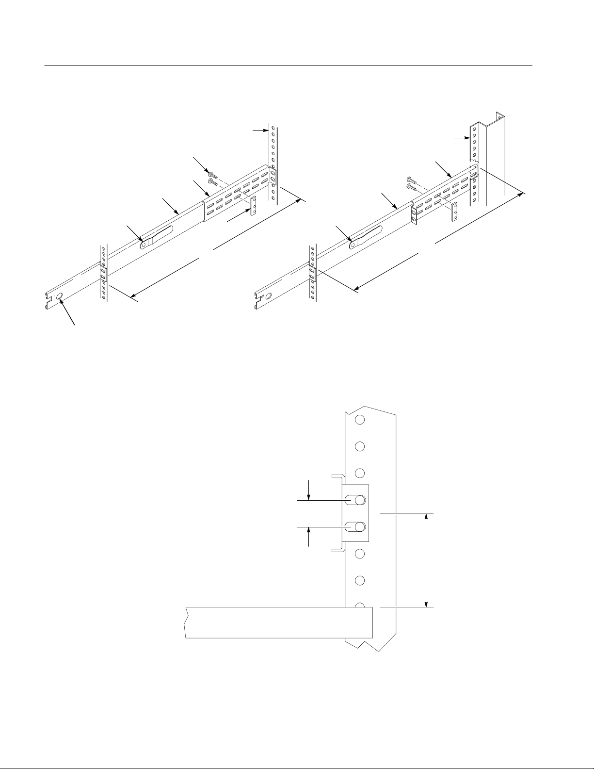
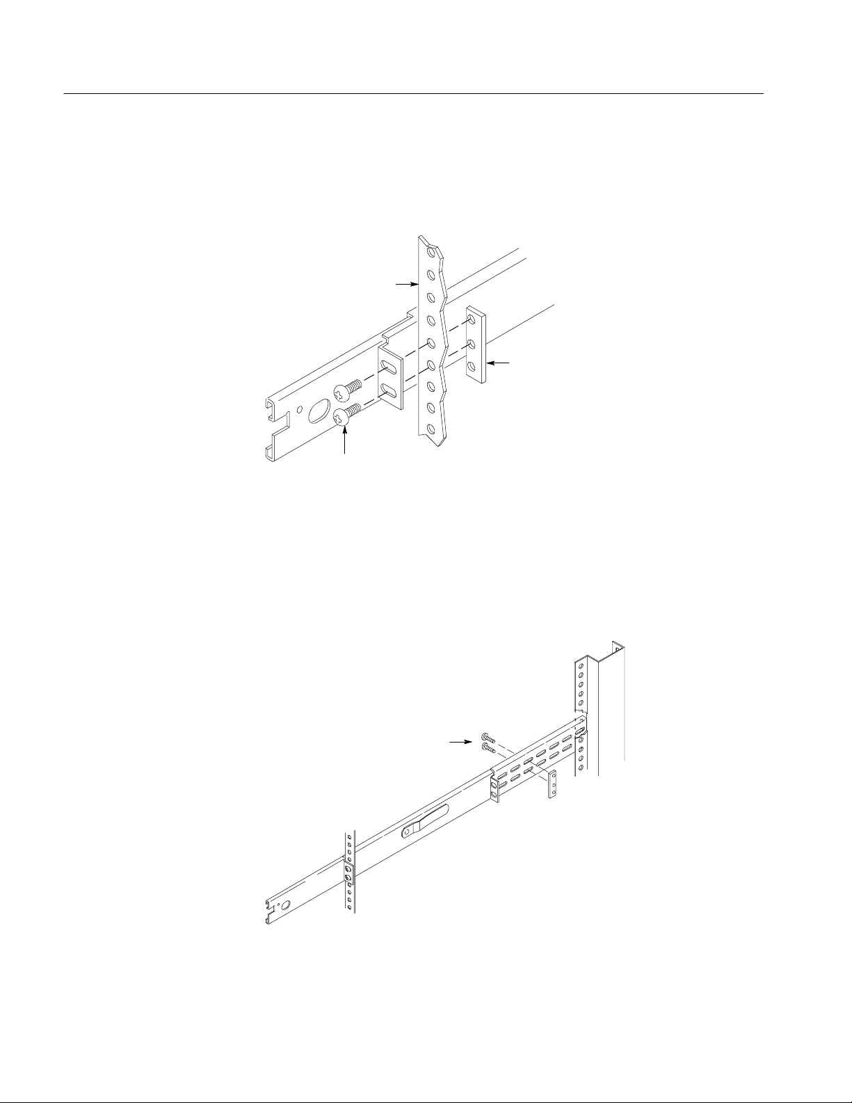
1. Attach the extension bracket to the rear of the stationary track.
a. Measure the distance between the front and rear rails of the equipment
rack using method A or method B. Refer to Figure 1--3.
H Method A. If the extension bracket is to be mounted against the front
edge of the rear rail in the equipment rack, measure from the front
edge of the rear rail to the front edge of the front rail.
H Method B. If the extension bracket is to be mounted against the
inside surface of the rear rail in the equipment rack, measure from
the front corner of the rear rail to the front edge of the front rail.
°C.
b. Attach the extension bracket to the rear of the stationary track so that the
length of the combined assembly is approximately that of the measurement taken in step a. above. Use the screws and bar nuts provided with
the chassis tracks. Leave the screws loose.
2. Select the appropriate mounting holes in the front rails of the equipment
rack, observing the clearance measurements shown in Figure 1--4. The front
panel of the rack adapter is designed to fit in an 11-inch high opening.
RFA300A Measurement Set 8VSB
1- 7
Page 22
Installation
Method A Method B
Rear rail
10-32 PNH screw
Extension bracket
Stationary track
Bar
Nut
Use this measurement
Stop latch
hole
Automatic latchAutomatic latch
NOTE: Right-hand and left-hand stationary sections are designated by the
RH and the LH marked on the rails. Stop latch holes should be towards
the bottom when slides are in place. (The right hand rail is shown above.)
Figure 1- 3: Attaching the extension brackets to the stationary tracks
Rear rail
Extension bracket
Stationary track
Use this measurement
1- 8
0.500 in.
1.75 in.
Adjacent equipment
Figure 1- 4: Mounting hole selection on the front rails of the equipment rack
REV SEP 1994
RFA300A Measurement Set 8VSB
Page 23
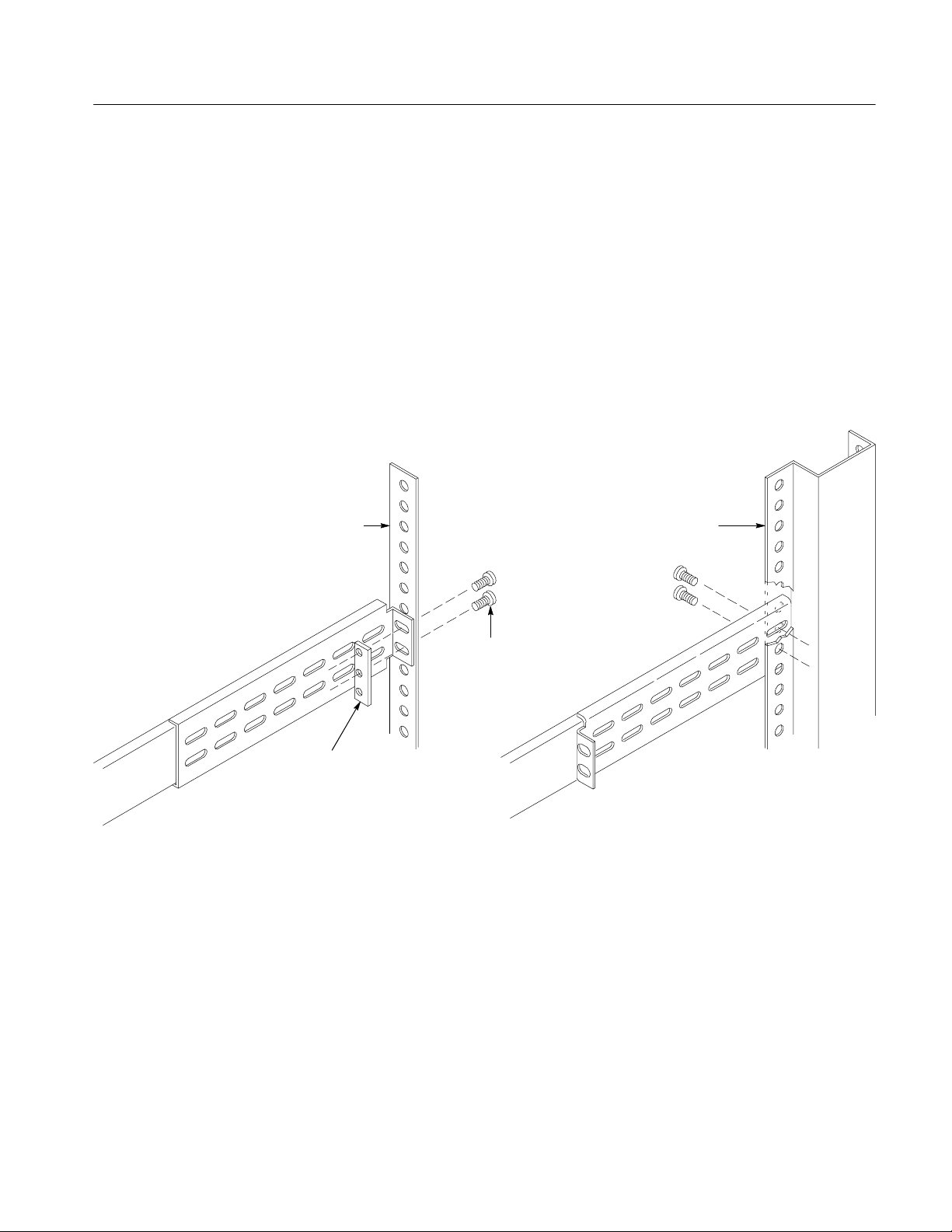
3. Mount the stationary sections (with extension brackets attached) to the front
and rear rails of the equipment rack.
a. Install the rear of the stationary section in front of, behind, or beside the
rear rail of the equipment rack. Use the mounting holes in the rear rails
that correspond to the same level as the front rail holes selected.
If the rear-rail mounting holes are tapped, the bar nut is not used to
attach the extensions. If the rear-rail mounting holes are not tapped, use
the bar nut on the inside of the rail, as shown in Figure 1--5A or use
suitable captive nut clips (not supplied). Figure 1--5B shows the
extension bracket mounted to the inside surface of the rear rail.
Method A Method B
Installation
Rear rail
10-32 PNH
screws
Bar nut (use
if rear rail is
not tapped)
Figure 1- 5: Attaching the extension bracket to the rear rail of the equipment rack
Rear rail
RFA300A Measurement Set 8VSB
1- 9
Page 24
Installation
b. Mount the stationary sections (with the bracket extensions) to the front
rails. If the front rails are not tapped, use the bar nuts. Refer to
Figure 1--6.
Front rail
Bar nut
(use if front rail
is not tapped)
10-32 PNH
screws
Figure 1- 6: Mounting the stationary section to the front rail of the equipment rack
4. Tighten the screws attaching the extension bracket to the stationary section.
Refer to Figure 1--7.
Tighten these screws
1- 10
Figure 1- 7: Stationary bracket, extension bracket, and attaching screws
RFA300A Measurement Set 8VSB
Page 25
Installation
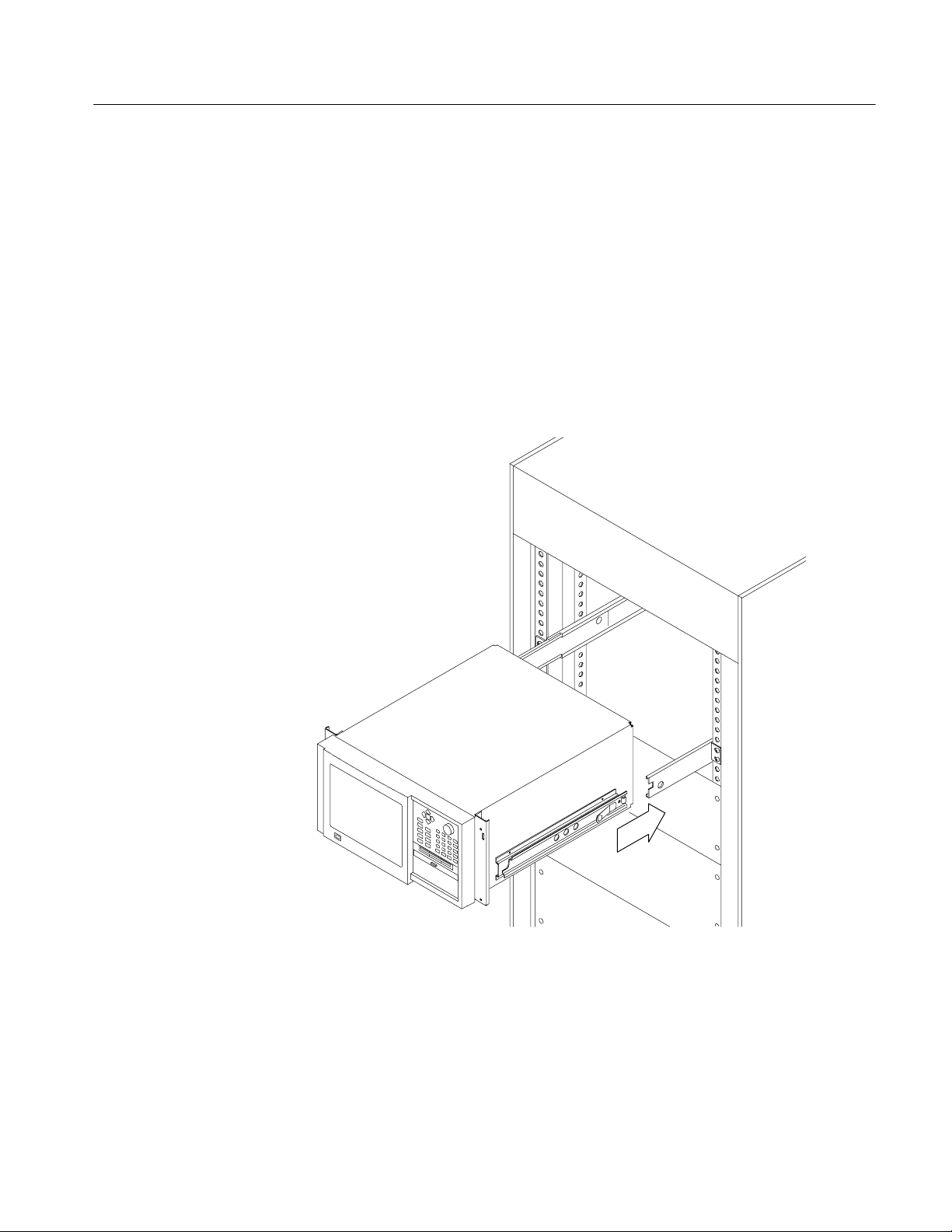
Installing the Instrument in the Equipment Rack. Perform the following steps to
install the instrument in the equipment rack:
1. Pull out the intermediate sections of each slide-out track to the fully
extended position. Refer to Figure 1--8.
2. Insert the tracks of the rack adapter into the slide-out intermediate sections.
3. Press both stop latch releases and push the rack adapter toward the rack until
the latches snap into their holes.
4. Again press the stop latches and push the rack adapter fully into the
equipment rack.
Figure 1- 8: Installing the instrument into the equipment rack
RFA300A Measurement Set 8VSB
1- 11
Page 26
Installation
5. If necessary, adjust the alignment of the stationary sections according to the
following procedure:
a. Loosen the mounting screws at the front of both stationary sections.
b. Allow the tracks to seek their normal positions with the adapter centered
in the rack.
c. Tighten the mounting screws.
Portable Installation
The optional portable cabinet allows you to operate the instrument on a bench or
cart. If you operate the instrument while it rests on the rear feet, make sure that
you properly route any cables coming out of the rear of the instrument to avoid
damaging them. Table 1--2 on page 1--4 lists the part number of the portable
cabinet.
CAUTION. Keep the bottom of the instrument clear of obstructions to ensure
proper cooling.
1- 12
RFA300A Measurement Set 8VSB
Page 27

Creating a Startup Disk
Installation
An RFA300A Windows NT Start Up disk is shipped with the instrument. Use
this disk to restart your measurement set in case of a major hardware or software
failure. This section creates an extra startup disk in case the original becomes
corrupted.
All software is installed at the factory. If you ever need to reinstall, refer to
Appendix C: Software Installation.
NOTE. You cannot reinstall software without a startup disk.
To create a startup disk, do the following:
1. Open My Computer/Control Panel, and double-click on Add/Remove
Programs.
2. Select the Startup Disk tab.
3. Click the Create Disk button and follow instructions.
4. Copy the following files to the startup disk:
H C:REALMODE\MSCDEX.EXE
H C:REALMODE\TEAC_CDI.SYS
H C:WINDOWS\COMMAND\XCOPY.EXE
H C:WINDOWS\COMMAND\XCOPY32.EXE
5. Create a file named AUTOEXEC.BAT in the startup disk. Add the line
MSCDEX.EXE /D:TEAC--CDI/L:D to the file.
6. Open the CONFIG.SYS file in the startup disk and add
DEVICE=TEAC_CDLSYS /D:TEAC--CDI to the end file.
RFA300A Measurement Set 8VSB
1- 13
Page 28
Installation
RF Connections
The quality of the input signal path is critical in obtaining the full-specified
performance of the measurement set. Therefore, you must connect the measurement set to your transmitter using high quality cable and connectors. The
following list provides the requirements needed for the RF connection:
H Hold the nonflatness of the input signal to approximately 0.05 dB peak-to-
peak or less over the width of the channel.
H Keep the station’s radiated signal to at least 63 dB down from the sampled
signal in the line by using appropriate shielding.
H The cable with connectors must have a return loss of at least 26 dB
(VSWR ± 1.10) over the channel width and a loss tilt of less than .02 dB
over the channel width. This assumes that the tap used to obtain the signal
has a return loss of ² 30 dB (VSWR ± 1.065).
High quality cable and connectors are required to meet the listed requirements.
The connectors should be precision grade at both ends of the cable. The best
cable type is dependent on the run length and operating frequency. The return
loss requirement is hardest to meet at high frequencies, and the loss tilt is hardest
to meet at low frequencies. In either case, minimize the difficulties by using only
a few feet for cable length. Longer lengths (50 ft. or more) place extreme
requirements on cable quality specifications.
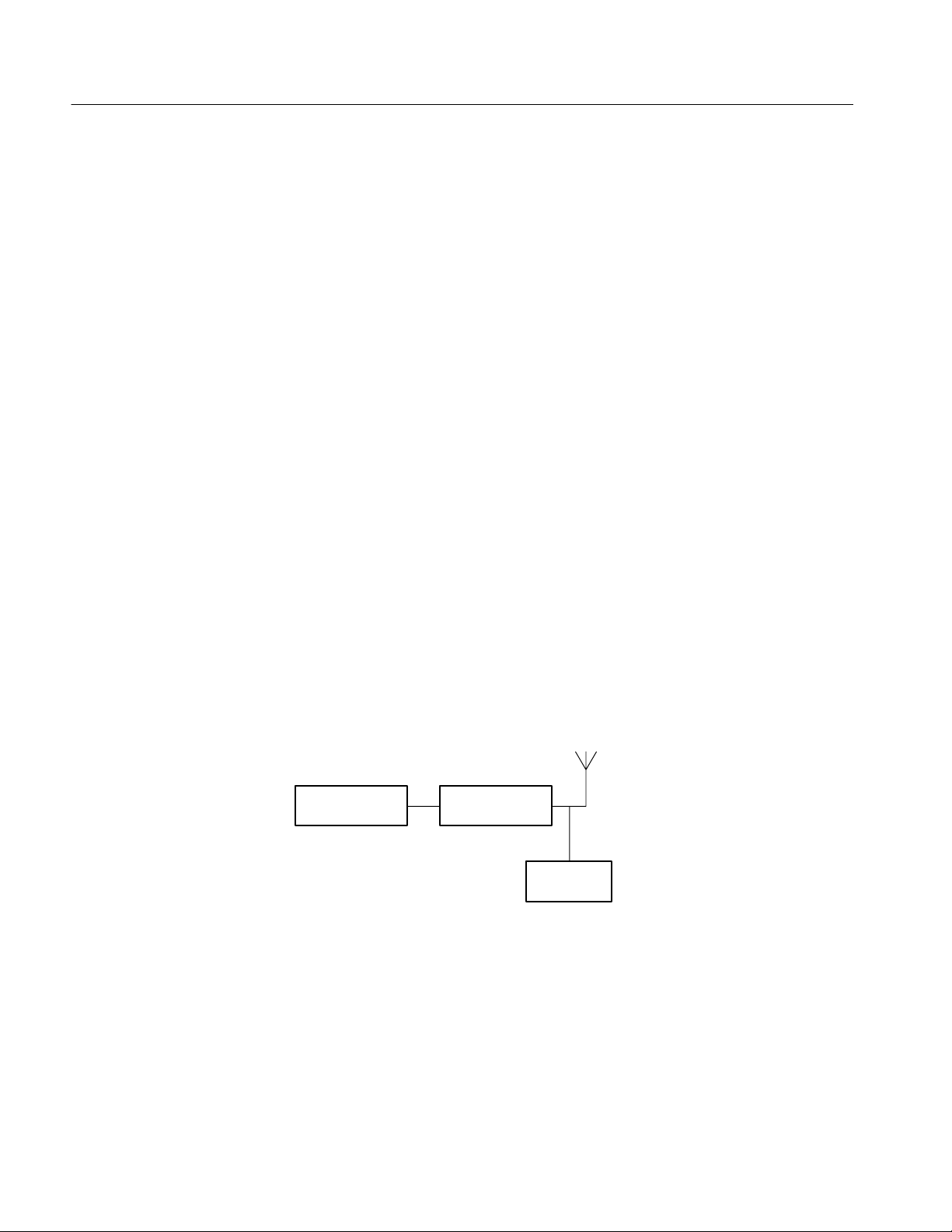
The rear panel provides two RF input connectors for your transmitted signal.
Refer to Figures 1--9 and 1--10 to connect the measurement set to your transmitter and for other connections.
Transmitter Channel filter
Power input
RFA300A
Figure 1- 9: Transmitter connection
Connect the measurement set to your transmitter in a manner that ensures the
instrument will receive only one channel. If the input signal strength is more
than 1 watt, install the external 10 dB attenuator (the input signal strength cannot
be more than 2 watts).
1- 14
RFA300A Measurement Set 8VSB
Page 29
Installation
NOTE. Power to the measurement set must be within the following ranges:
> 1 mW and < 1 W without the external 10 dB attenuator.
> 10 mW and less ≤ 2 W with the external 10 dB attenuator installed.
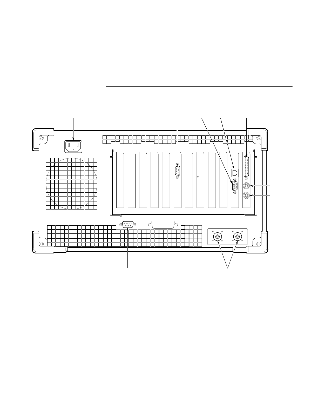
Power Alarm
SVGA
Ethernet
port
Parallel
port
Keyboard
Mouse
Figure 1- 10: Rear view
RFA300A Measurement Set 8VSB
RS-232
COM port 1
RF
connections
1- 15
Page 30
Installation
Interface Connections
The interface connectors on the rear and side of the RF measurement set, shown
in Figure 1--10 and Figure 1--11, provide the interconnection ports for peripheral
devices and networking. Pin assignments for the rear panel and side panel
connectors are listed in Table A--4 and Table A--5 in Appendix A:Specifications.
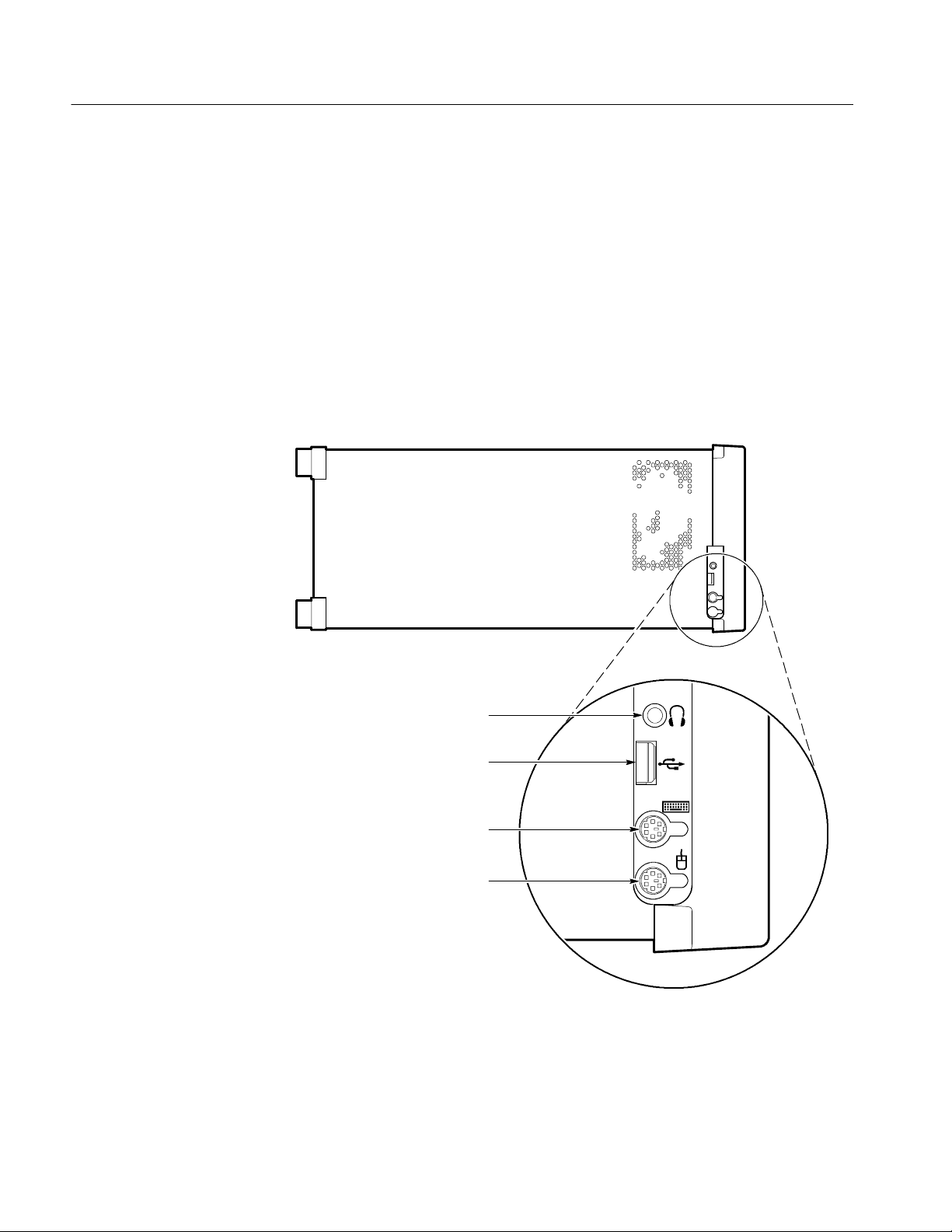
Keyboard and Mouse Connections
Connect the keyboard and mouse to the left side of the instrument as shown in
Figure 1--11.
Earphones
(Not used)
USB
Keyboard
Mouse
Figure 1- 11: Keyboard and mouse connections
1- 16
RFA300A Measurement Set 8VSB
Page 31

Powering On and Off
Installation
This section contains the procedure for powering on the instrument for the first
time. To power off the instrument, refer to Powering off on page 1--18.
First Time Power On
On/Standby switch
Power on the measurement set as follows:
1. Press the On/Standby switch to power on the instrument (see Figure 1--12 for
the switch location).
Figure 1- 12: On/Standby switch
2. Wait for the instrument to complete power-on self-tests.
RFA300A Measurement Set 8VSB
The screen displays an Enter Windows Password dialog box prompting you
for a logon name and password. However, if a password is entered then each
time you power on the measurement set you will be prompted for logon
information. To avoid this, do the following steps:
a. Enter a user name (for example, RFA300A) in the Enter Windows
Password dialog box.
b. Click OK, but do not enter a password.
c. Click OK in the Set Windows Password dialog box, but do not enter a
password.
1- 17
Page 32

Installation
3. Follow the instructions on the screen and enter the Windows NT Product
Identification number (located above the bar code) on the Windows NT
software package that came with your instrument. Enter other information as
required.
The internal setup software automatically configures your instrument and
installs all required devices. After the setup software completes configuration, the measurement set application will start.
The next time you power on, the application starts automatically. You do not
need to perform step 3 again.
Powering off
Always power off the instrument using the Windows NT shutdown process and
then press the On/Standby switch.
NOTE. Once a month, power down and restart the instrument. The measurement
set performs an internal calibration as part of the power on procedure. This
ensures the optimum measurement accuracy of the instrument.
Selecting RF Input Channel and Channel Frequency
Use the following procedure to select the RF Input channel, select the channel
frequency, and verify that the RF input signal has sufficient power. Without
sufficient power at the test signal input, the instrument cannot perform accurate
measurements.
1. Connect your transmitter to one of the RF input connectors shown on
page 1--15 (the connectors are internally terminated in 50
termination is needed).
2. If the input signal strength is more than 1 watt (but no greater than 2 watts),
make sure that the external 10 dB attenuator is installed.
Ω, so no external
1- 18
3. Power on the instrument.
4. Click the Setup button on the toolbar.
5. Click on the System tab to display the System page (shown in Figure 1--13).
RFA300A Measurement Set 8VSB
Page 33

Figure 1- 13: System setup
Installation
6. Click on the Input button to select the RF Input channel (Input 1 or Input 2)
to which you connected the transmitter. Only one of these channels can be
input at a time.
7. Enter the desired frequency.
NOTE. The frequency is the pilot frequency, not channel center. Refer to Selecting
channel frequency in the online help.
8. Click Apply, and then click the Input Signal Power button.
9. Check to see if the RF input signal level is in the OK range; if it is not, then
adjust the output of your transmitter accordingly.
10. Close the Input Signal Power dialog box and click OK to close the System
Setup window.
RFA300A Measurement Set 8VSB
1- 19
Page 34

Installation
Incoming Inspection
Incoming inspection consists of verifying basic operation of the measurement
set. The Power-on diagnostics check basic functionality. These diagnostics run
every time you power on the instrument. If a failure is detected, the Power-on
diagnostics dialog box opens with the failed test indicated.
Extended Diagnostics
Signal Power
Measurement
Functionality
Run the extended diagnostics to test functionality in more detail. To run
extended diagnostics, do the following procedure:
1. Go to the Tools menu and select Diagnostics.
2. Click the Extended Diagnostics tab.
3. Select All Modules and Tests and then select One Time.
4. Click Run and observe that a failure does not occur.
If a failure does occur, contact Tektronix using the information provided in the
Preface of this manual or click on Support located under the Help menu.
Perform the procedure on page 1--18 titled Selecting Channel Frequency and
verify that the RF input signal has sufficient power and is connected to the
selected RF input (1 or 2).
Open each measurement window and verify that activity is occurring. For
example, to check Frequency Response and Group Delay do the following
procedure:
1. From the Home window, click on the Frequency Response and Group Delay
icon to open the measurement window.
1- 20
2. Verify that a signal is visible in each waveform graphic within a few
seconds.
3. Verify that the readout for both measurements is updating.
Perform the same procedure for each measurement.
RFA300A Measurement Set 8VSB
Page 35

Operating Basics
Front Panel
This chapter describes the basic operation of the RFA300A Measurement Set
8VSB. For operating details, refer to the online help.
The front panel controls are used to operate the measurement set without the
mouse or keyboard. Figure 2--1 shows the front panel.
Figure 2- 1: Front panel
Keys
RFA300A Measurement Set 8VSB
You can use the front panel keys as an alternative to a keyboard. All keys and
key combinations critical to operating the instrument or for basic Windows tasks
are available via the front panel. To enter letters of the alphabet or special
characters, use the soft keyboard feature (refer to Entering text from the screen in
the online help).
For key combinations, it is unnecessary to hold down more than one key at a
time. For example, you can press SHIFT in the hex keypad, and then press
another key to accomplish a Shift+key combination. The same is true for other
key combinations, such as CTRL and ALT keys. This feature is often referred to
as a locked mode.
Table 2--1 lists front-panel key controls and describes their use.
2- 1
Page 36

Operating Basics
w
Table 2- 1: Front panel-key controls
Control name Mechanism Description
Up Arrow Button Use to navigate and change focus from one
Left Arrow Button
Right Arrow Button
Down Arrow Button
Select Button Same as the space key.
Adjust Knob Rotary encoder Multi-function control, increment/decrement
indow function toanother.
field values or screen element size or position.
Run/Stop Buttonwith3-color
LED
Esc Button Standard Escape key.
Tab Button Standard Tab key.
Print Button Prints current measurement using the same
Touch Button Toggles Touch Screen state on and off. LEDs
Menu (application key) Button Same as mouse button two.
Help Button Opens the Help contents. Standard F1 key
Print Screen Button Copies the screen to the clipboard. Alt plus
START Key Button Opens the Windows Start menu.
Numbers 0 to 9,
period and minus sign
Fctn ButtonwithLED Modifier for numeral keys to create keys F1
Del Button Deletes selected text or object.
Buttons Standard number keys, most have second
Button Backspace key.
Starts or stops a measurement. LED indicates
whether product is in Run or stop state.
print settings as for the previous print.
indicate Touch Screen On/Off state.
Print Screen copies the active window.
(Shift) and third (Function) functions.
through F12. Locked mode key feature. LED
indicates when on.
Button Enter key.
Ctrl ButtonwithLED Control key. LED indicates when keypad is in
control mode. Refer to Table 2--2 for a list of
control functions. Locked mode key feature.
Alt ButtonwithLED Alternate key. LED indicates when keypad is
in alternate mode. Locked mode key feature.
Space Button Space bar or use as mouse button 1
Shift ButtonwithLED Shift key. LED indicates when keypad is in
shift mode. Locked mode key feature.
2- 2
RFA300A Measurement Set 8VSB
Page 37

Table 2- 2: Control key combination functions
Control key Function
Ctrl+A Invokes the AutoScale function
Ctrl+B Opens the previous window (same as the toolbar<<Back)
Ctrl+C COPY
Ctrl+F Opens the following window (same as the toolbar Fwd >>)
Ctrl+H Opens the Home window
Ctrl+K Opens the Keypad dialog box
Ctrl+O Opens the Recal l Results dialog box
Ctrl+P Prints the measurement
Ctrl+S Saves the results of the current measurement
Ctrl+T Toggles the Touchscreen on or off
Ctrl+V PASTE
Ctrl+X CUT
Operating Basics
Touch Screen
Soft Keyboard
Ctrl+Y REPEAT
Ctrl+Z UNDO
The touch screen allows you to use your finger instead of a mouse. Move your
finger around the screen to move the cursor. Tap to select an object and select
ENTER to activate the object.
You can use the soft keyboard with any application. To display the soft keyboard, select My--T--Soft from the Program menu, click the keyboard icon in the
System Setup menu, or click a keyboard icon displayed in an application.
You can configure the keyboard (change the size, for example). To do this, click
the icon shaped like a hand in the upper right corner of the keyboard display to
access a dialog box.
Tutorial. For a tutorial on how to use the soft keyboard, select My--T--Soft
Welcome from the My--T--Soft program group (in Programs in the Windows
startup menu).
Licensing. If the RFA300A software is correctly installed the first time you use
the soft keyboard, the My--T--Soft keyboard registers itself. If the RFA300A is
not installed, the My--T--Soft keyboard will be loaded as a demo version. To
undo this, uninstall the My--T--Soft keyboard, properly install the RFA300A
software, and then reinstall the keyboard.
RFA300A Measurement Set 8VSB
2- 3
Page 38

Operating Basics
Home Window
To display the license status, select Licensing from the My-T-Soft program
group (from Programs in the Start Up menu).
NOTE. The My-T-Soft keyboard must be installed on the same drive letter as the
RFA300A software.
The Home Window is the point-of-entry into the measurement set. From the
home window, you access all measurements by clicking on the appropriate icon.
A measurement begins to run immediately when the window opens. Figure 2--2
shows the Home window. Refer to the Reference chapter for an overview of each
measurement window.
RFA300A -- Home
2- 4
Menus
Toolbar
Figure 2- 2: Home window
Menu selections are available from any measurement window and the Signal
Monitor window. Refer to the online help for a description of each menu selection.
All toolbar selections are available from any measurement window and the
Signal Monitor window. The toolbar provides an easy method for accessing
frequently-used functions. Figure 2--3 shows the toolbar and Table 2--3 lists the
toolbar functions.
RFA300A Measurement Set 8VSB
Page 39

Operating Basics
Recall
Results
Results
Save
Print
Edit
Setup
Smoothing
Selection
Run
Status
Run/Stop
Button
Back & Forward
Home
Figure 2- 3: Toolbar
Table 2- 3: Toolbar functions
Toolbar selection Function
Recall Results Recalls a previously saved measurement.
Save Results Save the results of the current measurement.
Print Prints one copy of the current measurement.
Edit Setup Provides setup controls for the instrument and measurements.
What’s
This?
Smoothing Selection Selects the degree for reducing the variations of the waveform and
results. Smoothing is accomplished differently for each type of
measurement. Refer to the online help for each measurem ent
window to determine how smoothing is accomplished.
Run Status Shows when the measurement is running or stopped. Red is
stopped and green is running.
Run/Stop Button Begins or stops performing measurements.
Back and Forward Back opens the previously opened window. Forward opens the
following window.
Home Returns to the Home window.
What’s This? Provides a brief description of the sel ected control or object.
RFA300A Measurement Set 8VSB
2- 5
Page 40

Operating Basics
Making a Measurement
The following provides a basic overview of how to make and save a measurement. Refer to the online help for details on other operating features. An
explanation of how help works is on page 2--9.
Selecting Frequency
Limits Versus Masks
Limits
Before running measurements you must select your channel frequency and
determine that the input signal has power within the correct range. Refer to
Selecting RF Input Channel and Channel Frequency on page 1--18 for the
procedures on selecting channel frequency and checking input signal power.
Before proceeding, you should understand the differences between limits and
masks. Limits are parameters against which numeric measurement results can be
compared automatically. You can choose the color to highlight results that
violate parameters.
The mask-testing feature allows you to set visual parameters within the graphic
portion of the measurement window. The masks are lines against which you can
compare waveforms.
After selecting your channel frequency and checking input signal power, you can
edit caution and alarm limits. The instrument compares each new result against
the current limits as soon as you enter the measurement window. To edit limits,
do the following:
1. Click the Setup button located in the toolbar.
2. Click the Limits tab.
2- 6
3. Select which results are to be compared against the limits when the
measurement is running.
4. Enter the low value for Alarm. The value must be less than the low Caution
value.
5. Enter the low value for Caution. The value must be less than High Caution
and greater than Low Alarm.
6. Enter the high value for Caution. The value must be less than High Alarm
and greater than Low Caution.
7. Enter the high value for Alarm. The value must be greater than High
Caution.
For some measurements, you cannot enter values for all limits because it would
be counter productive. For example, there is no reason to set a high caution or
alarm value for signal-to-noise when you want the signal-to-noise ratio to be as
high as possible.
RFA300A Measurement Set 8VSB
Page 41

Operating Basics
Masks
Viewing Results
The mask-testing feature is not on when you receive your measurement set. To
turn masks on and off or to select different masks, do the following:
1. Open a measurement window. For example, open the Amplitude and Phase
Error window.
2. Click the Setup button located in the toolbar.
3. Select the appropriate box to enable a mask test. The mask is enabled when
checked.
4. Select the mask you want to use.
5. Click OK to accept your changes and return to your measurement window.
Not all of the measurements need or include a mask test. Those that do not are
the Signal/Noise, Error Vector Magnitude, and Pilot Amplitude Error window
and Peak/Average and Channel Spectrum window.
You can create a mask for those measurements that include mask testing. Refer
to Mask file formatting in the online help.
Once you open a measurement window, notice that the measurement runs and
provides results soon after the window opens. To stop the measurement, press
the Stop button located in the toolbar. To restart, press the Run button.
Saving Results
Signal Monitor
After making a measurement, you can save your results to a database by doing
the following:
1. Go to the File menu and select Save Results As.
2. Enter name, destination, and any notes you want saved with the results.
Results can be printed or exported to other applications using the Report dialog
box selected in the File menu. You can also recall results for further study at any
time.
The Signal Monitor allows you to continuously monitor one or more of the other
measurement’s numeric results in one window. To select the measurements to
monitor, do the following:
1. Open the Signal Monitor window.
2. Click Setup in the Toolbar.
3. Select the measurements you want to monitor.
4. Select how often you want your results to be automatically saved or select
Off to disable the function.
RFA300A Measurement Set 8VSB
2- 7
Page 42

Operating Basics
5. If you selected At Intervals in step 4, enter the amount of hours to save
between AutoSave actions.
NOTE. An indication of how long the instrument can run before running out of
space is provided. Click the File Size button to limit the size of your result
database files. Refer to Limiting the size of a results database file in the online
help.
6. Select when to be notified (under Notification Criteria) if a caution, alarm, or
error occurs. You can also select not to be notified.
7. If you selected to be notified in step 6, select the notification action.
NOTE. Before you can set up Email notification, you must install a Messaging
Application Program Interface (MAPI) compliant Email application.
8. Click the Email Settings button to change Email parameters.
NOTE. Selecting Send Email opens the Email dialog box if the destination is not
yet specified. You can enter the address, include a message, and send the current
results or only results that have violated limits.
9. Click Suspend Actions and select how often you want to be notified.
10. Click OK to close.
11. Click the Setup’s OK button to apply your selections and return to the Signal
Monitor window.
2- 8
RFA300A Measurement Set 8VSB
Page 43

Online Help
Operating Basics
The online help gives detailed information about the operation of the measurement set. Look in the online help for details about user selections and controls
that are not described in this manual.
To access online help, go to the Help menu as shown in Figure 2--4.
Click for Topic help.
Click for What’s This? help on selected object.
Figure 2- 4: Help menu
Help Topics
What’s This? Help
Help topics tell you how to perform tasks and describe software features and
selections shown on the screen. There are two types of help topics, reference
topics and task topics.
Reference topics describe application features, such as the measurement
windows. Reference topics may also describe concepts. Reference topics are
available through the Help menu and through Help buttons in dialog boxes.
From the Help menu, click Help Topics, and locate the topic using the Contents
or Index tab. The Index tab is easier to use. As you enter a word into the text
field, Help searches for and highlights the topic if one can be found. If not, try
the Find tab. Enter a word or phase and help will display all topics that contain
the word or phrase. The Help on Window selection in the Help menu provides
reference help for the current window.
Task topics provide procedure information on how to perform specific tasks.
Task topics are available through the Help menu. From the Help menu, click
Help Topics, and locate the topic using the Contents or Index tab.
What’s This? help provides a short description of the control or screen feature
selected. First, click the What’s This? button on the toolbar as shown in
Figure 2--4, and then click the item of interest.
RFA300A Measurement Set 8VSB
2- 9
Page 44

Operating Basics
Windows NT Online Help
Release Notes
Backing Up Files
Information about Windows features is available through the Windows help
system. Access Windows help as you would with any Windows application:
1. Go to the Windows taskbar and click Start.
2. Select Help from the popup menu.
NOTE. To access Windows NT help using the Touchscreen, press the START key
on the font panel.
The online Release Notes contain information about this release of the RFA300A
application. Check the Release Notes for information such as software compatibility and software version differences from last release.
To access the Release Notes, go to the Windows NT taskbar and click Start, or
press the front panel START key. The Release Notes are at the top of the Start
menu.
You should back up your files on a regular basis. Use the Windows Back Up tool
to back up files stored on the hard disk. The Back Up tool is located in the
following path: Programs\Accessories\System Tools\Back. Start the tool and
determine which files and folders you want to back up. Use the Windows online
help for information on using the Back Up tool.
In particular, you should back up your user-generated masks, setup files, and the
results database files.
2- 10
RFA300A Measurement Set 8VSB
Page 45

Reference
This section gives an overview of each measurement within the measurement set
and the 8VSB transmitter.
Out of Channel Emissions
This section provides an overview of the Out of Channel Emissions measurement window. For more in-depth information, refer to the online help.
Out of Channel Emissions is a vital measurement that is specified by the FCC.
To prevent interference outside of the allotted spectrum, the RF signal must
comply with the specified mask for the transmitter under test.
NOTE. The measurement set is limited to measurements between 0 and -80 dB on
the FCC’s scale.
The measurement set performs the measurement by calculating the power of the
signal that passed through an ¶ 30 kHz filter before being digitized. The
measured values are adjusted to an equivalent 500 kHz noise bandwidth and
divided by the total transmitter output power. This is the FCC measurement
method.
The Out of Channel Emissions measurement window is shown in Figure 3--1.
The measurement window contains the following areas:
H A listing of measurement results.
H A mask test pass or fail indicator.
H Controls for selecting the number of channels to display.
H Controls for resolution.
H Cursor direction controls.
H A listing of each cursor’s position and the difference between the two.
H Graphic showing the spectral waveform with the selected mask overlaid on
the spectrum display, if enabled from the setup (refer to Out of Channel
Emissions Setup next).
RFA300A Measurement Set 8VSB
3- 1
Page 46

Reference
Results listing
Mask indication
Resolution
Channel controls
Cursor position
Cursor directions
Out of Channel
Emissions Setup
Figure 3- 1: Out of Channel Emissions measurement window
Click the Setup button in the toolbar to enable mask testing and select a mask for
the measurement window. The setup dialog box contains the control for turning
masks on and off, plus a list of available masks. You can create your own mask
and place it into the measurement set for use. Refer to Appendix D: Mask File
Formatting in this manual for detailed instructions. Figure 3--2 shows the Out of
Channel Emissions setup.
3- 2
Figure 3- 2: Out of Channel Emissions setup
RFA300A Measurement Set 8VSB
Page 47

S/N, EVM, and Pilot Amplitude Error
This section provides a brief overview of the Signal-to-Noise, Error Vector
Measurement, and Pilot Amplitude Measurement window. For more in-depth
information, refer to the online help.
The S/N, EVM, and Pilot Amplitude Error measurement window provides an
overview of the transmitter’s 8VSB signal quality. Signal-to-Noise (S/N), Error
Vector Magnitude (EVM), and Complex Modulation Error Ratio (MER) are
similar measurements. The calculations for each are slight deviations from each
other. Refer to S/N, EVM, and Complex MER calculations in the online help.
Figure 3--3 shows the measurement window with the constellation display. The
window contains the following areas:
H A listing of measurement results.
H Two display graphics: constellation and eye diagram.
H A control for turning equalization on and off. Equalization removes linear
distortions from the measurements. This allows you to distinguish among
causes of poor signal quality.
Reference
Results listing
Controls
S/N
H A control for subtracting the pilot amplitude from the horizontal axis.
RFA300 A -- Signa l / Noise & EVM
Figure 3- 3: S/N, EVM, and Pilot Amplitude measurement window
The S/N measurement provides a broad measure of impairments in the transmitted signal. S/N is the power ratio between the ideal received signal and the
difference between the ideal and actual received signal as measured along the
real axis during symbol times only. A comparison is made between the deviation
RFA300A Measurement Set 8VSB
3- 3
Page 48

Reference
of the actual digitally modulated television signal and an ideal signal of the same
data. This measurement is the major all-in-one indicator of the transmitter’s
signal quality. The test is an early indication of system problems before they
become bit errors and is more sensitive to modulation errors than Bit Error Ratio
(BER) tests.
Complex MER
Pilot Amplitude Error
Phase Noise
EVM
The EVM (Error Vector Magnitude) measurement also provides a broad analysis
of the transmitted signal. EVM analysis can reveal incorrect filter shaping (see
VSB Modulation on page 3--18) and other modulation quality problems.
Complex MER is a complex form of S/N. The measurement is made by
including Q (quadrature) channel information into the calculation. Refer to
Complex MER calculation in the online help.
This measurement shows any error of the pilot signal amplitude.
This section provides a brief overview of the Phase Noise measurement window.
For more in-depth information, refer to the online help.
This measurement window measures the random low frequency phase deviations
of the entire 8VSB signal. Phase noise is typically added by the transmitter’s
frequency synthesizer system. Phase noise can reduce the S/N ratio.
3- 4
The measurement set performs this measurement by calculating the residual
phase jitter. This jitter is what is left after removing the effects of other transmission errors.
The Phase Noise measurement window is shown in Figure 3--4. The measurement window contains the following areas:
H Listing of measurement results
H A mask test pass or fail indicator
H Cursor direction controls
H Listing of each cursor’s position and the difference between the two
H Graphic showing the pilot’s phase noise spectral density measured in dBc/Hz
versus frequency. The selected mask is overlaid on the display, if you
enabled any in the setup (see Phase Noise Setup next).
RFA300A Measurement Set 8VSB
Page 49

Results listing
Mask indication
Cursor position
Cursor directions
Reference
RFA300A -- Phase Noise
Figure 3- 4: Phase Noise Measurement window
Phase Noise Setup
Click the Setup button in the toolbar to enable and select a mask for the
measurement window. The setup dialog box contains the control for turning
masks on and off, plus a list of available masks. You can create your own mask
and place it into the measurement set for use. Refer to Appendix D: Mask File
Formatting in this manual for detailed instructions. Figure 3--5 shows the Phase
Noise setup.
Figure 3- 5: Phase Noise setup
RFA300A Measurement Set 8VSB
3- 5
Page 50

Reference
Frequency Response and Group Delay
This section provides a brief overview of the Frequency Response and Group
Delay measurement window. For more in-depth information, refer to the online
help.
This measurement measures frequency response and group delay errors. These
errors are the result of linear distortion caused by transmitter imperfections or
possibly small impedance mismatches or both.
The frequency response errors are listed in dB. The frequency at which the
minimum and maximum errors were found is also shown. Group delay errors are
in nanoseconds.
The measurement set calculates these measurements by deriving the amplitude
and time delay response of the channel from the equalizer tap coefficients.
Frequency response and group delay are calculated relative to the pilot frequency
or the center of the channel as selected in the setup.
The Frequency Response and Group Delay measurement window is shown in
Figure 3--6. The measurement window contains the following areas:
H A listing of measurement results.
H Cursor direction controls.
H A mask pass or fail indicator for each measurement.
H A listing of each cursor’s position and the difference between the two.
H Graphics showing frequency response measured in dB versus frequency and
group delay measured in time (nanoseconds) versus frequency. Selected
masks are overlaid on the display, if you enabled any in the setup (refer to
Frequency Response and Group Delay Setup next).
3- 6
RFA300A Measurement Set 8VSB
Page 51

Results listing
Mask indication
Cursor position
Cursor directions
Reference
RFA300 A -- F req uen cy Res ponse & Group Delay
Figure 3- 6: Frequency Response and Group Delay measurement window
Frequency Response and
Group Delay Setup
Click the Setup button in the toolbar to enable and select a mask for each
measurement in the measurement window. In addition, the setup has a reference
point selection for the measurements: either channel center or the pilot. The
setup contains the control for turning masks on and off, plus a list of available
masks. You can create your own mask and place it into the measurement set for
use. Refer to Appendix D: Mask File Formatting in this manual for detailed
instructions. Figure 3--7 shows the Frequency Response and Group Delay setup.
Figure 3- 7: Frequency Response and Group Delay setup
RFA300A Measurement Set 8VSB
3- 7
Page 52

Reference
Amplitude and Phase Errors
This section provides a brief overview of the Amplitude and Phase Errors
measurement window. For more in-depth information, refer to the online help.
This measurement measures amplitude and phase errors, which are nonlinear
distortions. A signal’s phase can shift with amplitude. Transmitters, particularly
high power ones, can exhibit amplitude errors in the form of clipping or
compression when close to full power. These errors decrease a transmitter’s
Signal-to-Noise ratio, thereby reducing the coverage area.
The measurement set performs the measurement by calculating ideal signal
magnitude and phase from the received I/Q signal and comparing it with the
actual signal.
The Amplitude and Phase Errors measurement window is shown in Figure 3--8.
The measurement window contains the following areas:
H A listing of measurement results.
H A mask test pass or fail indicator for each measurement.
H Cursor direction controls.
H A listing of each cursor’s position and the difference between the two.
H Graphics showing signal amplitude error versus ideal signal amplitude
measured in dB versus constellation units (refer to the Glossary) and signal
phase errors versus ideal signal amplitude measured in degrees versus
constellation units. The selected masks are overlaid on the graphics, if
enabled from the setup (refer to Amplitude and Phase Errors Setup next).
3- 8
RFA300A Measurement Set 8VSB
Page 53

Results listing
Mask indication
Cursor position
Cursor directions
Reference
RFA300A -- Amplitude & Phase Errors
Amplitude and Phase
Errors Setup
Figure 3- 8: Amplitude and Phase Errors measurement window
Click the Setup button in the toolbar to enable and select masks for the measurement window. The Setup dialog box contains controls for turning masks on and
off and selections for using different masks. You can create your own mask and
place it into the measurement set for use. Refer to Appendix D: Mask File
Formatting in this manual for detailed instructions. Figure 3--9 shows the
Amplitude and Phase Errors setup.
Figure 3- 9: Amplitude Error and Phase Error setup
RFA300A Measurement Set 8VSB
3- 9
Page 54

Reference
Peak-to-Average and Channel Spectrum
This section provides a brief overview of the Peak-to-Average and Channel
Spectrum measurement window. For more in-depth information, refer to the
online help.
This window measures the cumulative distribution of peak power over time.
Peak power is the maximum value of envelope power that is randomly reached
by the digitally modulated signal. Power amplifiers driven beyond their
capability cause compression of peaks. This distorts the signal causing out of
channel emissions and lower signal-to-noise ratio.
The measurement is calculated by taking the percentage of time that the signal is
greater than the average amplitude. This measurement and the ideal are both
plotted on the Peak-to-Average graph.
The Peak-to-Average and Channel Spectrum measurement window is shown in
Figure 3--10. The measurement window contains the following areas:
H Listing of measurement results.
Results listing
Target operating
point control
H A selection control for setting the target operating point in the peak-to-aver-
age graphic. Select the target operating point method in the setup (refer to
Peak-to-Average Setup next).
H Graphics showing the measured and ideal peak-to-average power curves and
the channel spectrum. The channel spectrum is another tool to assess a
transmitter’s amplitude linearity. To view this graph, click on the Channel
Spectrum tab.
RFA300 A -- Peak / Ave rag e & Ch ann el Spec tru m
3- 10
Figure 3- 10: Peak-to-Average and Channel Spectrum measurement window
RFA300A Measurement Set 8VSB
Page 55

Reference
Peak-to-Average Setup
Click the Setup button in the toolbar to select the target operating point method
for the measurement window. You can select in dB or percentage of time.
Figure 3--11 shows the Peak-to-Average Setup.
Figure 3- 11: Peak-to-Average Setup
RFA300A Measurement Set 8VSB
3- 11
Page 56

Reference
Signal Monitor
This section provides a brief overview of the Signal Monitor measurement
window. For more in-depth information, refer to the online help.
The Signal Monitor allows you to continuously monitor one or more of the other
measurements in one window while the instrument is unattended. You can enter
the setup for each measurement in each measurement’s Setup dialog box. Set all
cautions and alarms in the Limits dialog box (refer to Limits on page 2--6). The
selection of which measurements to monitor is made in the Signal Monitor
Setup. Figure 3--12 shows the Signal Monitor measurement window.
RFA300A -- Amplitude & Phase Errors
3- 12
Figure 3- 12: Signal Monitor measurement window
RFA300A Measurement Set 8VSB
Page 57

Reference
Signal Monitor Setup
Measurement selections
In addition to selecting measurements to monitor, you can also select the
following in the Signal Monitor Setup:
H How often to save your results automatically, if at all.
H Size limit for the results database file.
H When and how to be notified of caution, alarm, and error conditions.
Choices of how to be notified include sound, saving results, email, and by
activation of an external device (see Figure 1--10 on page 1--15 for the alarm
connection location).
H How often or when to be notified.
Figure 3--13 shows the Signal Monitor Setup.
AutoSave controls
Notification controls
Figure 3- 13: Signal Monitor Setup
RFA300A Measurement Set 8VSB
3- 13
Page 58

Reference
8VSB Overview
This section provides an overview of the 8VSB transmitter. For a complete
understanding of the transmitter, refer to Advanced Televisions Systems
Committee (ATSC) Digital Television Standard document A/53. This document
is available from the World Wide Web at ftp://atsc.org/pub/Standards.
The 8VSB standard is a RF modulation format used to broadcast Digital
Television (DTV) to the home. This format was proposed by the ATSC and
adopted by the FCC. The 8VSB transmitter generates the 8VSB signal as shown
in Figure 3--14. The transmitter must take the bit-stream output from a MPEG II
encoder and transmit it on a 6 MHz RF channel.
Data Randomizer
Data
Randomizer
Pilot
Insertion
Reed-Solomon
Encoder
Modulator
VSB
Data
Interleaver
Upconverter
Segment Sync
RF
Trellis
Encoder
Field Sync
RFA300A
Input Signal
MUX
Figure 3- 14: 8VSB exciter block diagram
To use the 6 MHz channel space with maximum efficiency, the 8VSB bit stream
must be randomized with a pseudo-random bitstream. This ensures a flat
noise-like spectrum and reduces interference to NTSC channels. A recurring
rhythmic pattern causes the RF energy content to cluster at certain areas in the
frequency spectrum. Therefore, without additional processing, certain parts of
the 6 MHz channel could be overused, while other areas are underused. The Data
Randomizer changes each byte value to a known pseudo-random binary
sequence (PRBS). The PRBS process is reversed in the television receiver to
recover the correct data value.
Reed-Solomon Encoder
3- 14
The Reed-Solomon (RS) encoder uses Forward Error Correction (FEC) to
correct received bit errors that can occur during transmission. The RS encoder
takes the 187-byte data block and adds 20 parity bytes. The receiver compares
the 187-byte block to the 20 parity bytes to determine if the data is valid. RS
encoding can correct up to 10 byte errors per one 187-byte data block (packet).
RFA300A Measurement Set 8VSB
Page 59

Reference
Data Interleaver
Some noise burst durations are longer than the RS encoder can manage. For
further protection, a time diversity scheme called data interleaving is used. Refer
to Figure 3--15.
c3, c2, c1, b3, b2, b1, a3, a2, a1
c3, b3, a3, c2, b2, a2, c1, b1, a1
Noise
burst
Non-interleaved
Interleaved
Figure 3- 15: Data interleaving
A noise burst could delete all the b bytes of a non-interleaved signal resulting in
a loss that the RS decoder in a receiver cannot recover. However, if the data is
interleaved, only one byte is lost in each of the a, b and c byte segments of the
interleaved signal. This leaves enough data for the decoder to determine the
correct value. In reality, 8VSB data is interleaved to a depth of 52. This allows
the decoder to determine the correct value of data that has been damaged by a
193 µs noise burst.
Trellis Encoder
A Trellis Encoder is another Forward Error Correction method. However, where
as the RS encoder dealt with the entire data packet as a block, the Trellis encoder
affects the stream of bits as they develop through time. Trellis encoding is
accomplished by Trellis-Coded Modulation (TCM). TCM is a combination of
coding and modulation that does not require additional bandwidth expansion
although there are extra bits for FEC.
The Trellis encoder takes an eight-bit byte and splits it into four two-bit words.
Every two-bit word is compared with previous words. A three-bit code is
assigned to each two-bit word that describes the transition from the previous
word to the current one. Therefore, for every two bits in, the encoder produces
three bits out. The Trellis decoder (Viterbi) in a receiver uses the three bits to
reconstruct the evolution of the data stream from one two-bit word to the next.
The Trellis and Viterbi coding scheme is very effective in managing white noise.
RFA300A Measurement Set 8VSB
3- 15
Page 60

Reference
Multiplexer
Supplementary sync signals are added to a multiplexer to form the 8VSB
baseband signal. Each of the eight levels represents a symbol value. After every
828 symbols, a Segment sync is sent. The Segment sync is two-level binary data
that is 10 constellation units peak-to-peak in amplitude and four symbols long.
This makes each 8VSB data segment 832 symbols long as shown in Figure 3--16. The Segment sync has two roles: it replaces the sync byte that was
removed before the RS encoding, and it increases the signal robustness. It is
easily located by the receiver’s decoder in the presence of noise.
Data
segment
sync
Levels
before
pilot
insertion
+7
+5
+3
+1
Data
segment
sync
-1
-3
-5
Data + FEC
-7
4
Symbols
1byte
828 Symbols = 187 data bytes + 20 parity (R-S) bytes
832 Symbols = 188 byte MPEG data packet + 20 parity bytes
Figure 3- 16: Data segment sync
4
Symbols
1byte
3- 16
RFA300A Measurement Set 8VSB
Page 61

Reference
The other sync signal added to the multiplexer is the Frame synchronizing
segment. As shown in Figure 3--17, a transmission data frame is 616 segments
(48.4 ms) long. A Frame sync segment is sent every 313 segments (24.2 ms).
The Frame sync segment carries the training reference signals for the receiver
equalizer. It consists of the following:
H Four byte segment sync.
H Five hundred and eleven reference symbols that the receiver uses for
adjusting long equalizer taps.
H Three sets of 63 reference symbols for short equalization.
H Twenty-four symbols for VSB level ID.
H Ninety-two reserved symbols.
H Twelve symbols repeated from the previous segment.
313 Segments
(24.2 ms)
313 Segments
(24.2 ms)
4
828 Symbols
Frame Sync #1
Frame Sync #2
Figure 3- 17: Frame synchronizing segment
1 Segment =
832 Symbols =
77.3 s
RFA300A Measurement Set 8VSB
3- 17
Page 62

Reference
Pilot Insertion
VSB Modulation
A small DC offset is added to the baseband signal to produce a pilot at the carrier
frequency of the resulting modulated spectrum. The pilot is 0.3 dB of average
signal power and is used by the receiver for carrier acquisition. The receiver then
uses the Segment sync to lock on the s ymbol timing.
The 8VSB signal is transmitted as a single sideband suppressed carrier signal.
The baseband signal is typically mixed with a 44 MHz signal and passed through
a root-raised cosine filter. The output is a 44 MHz IF signal, upper sideband
only, with root-raised cosine response.
Closed-Loop Transmitter Control
This section provides a brief overview of the closed-loop feedback system that
can be used to control a transmitter exciter to maintain the signal within required
transmitting parameters.
Correction Processor
A correction processor is either a closed-loop correction system or an open-loop
correction system, depending on how advanced the transmitter is. The correction
processor is used to shape the exciter signal to precorrect for frequency response
and envelope delay errors in the transmitter power amplifier. Precorrection can
also reduce non-linear errors.
A closed-loop system samples the outgoing RF to determine what type and how
much correction is needed and adjusts the precorrection accordingly. A less
advanced transmitter can have an open-loop precorrection system that requires
manual adjustments to the controls in a shaping network to produce the corrected
output.
3- 18
RFA300A Measurement Set 8VSB
Page 63

Appendix A: Specifications
This section lists the electrical, physical, and environmental characteristics of the
RFA300A Measurement Set 8VSB.
Specification Tables
The tables list the specifications for the RFA300A Measurement Set 8VSB. All
specifications are guaranteed unless labeled typical. Typical specifications are
provided for your convenience but are not guaranteed. Specifications marked
with the n symbol are checked in the Performance Verification Procedures (refer
to the RFA300A Measurement Set 8VSB Service Manual).
Performance Conditions
The Performance requirements are valid within the environmental limits if the
instrument was adjusted at 25 _C ± 5 _C and you allowed a minimum warm-up
time of 20 minutes.
The measurement set is limited to situations where a single, high-amplitude,
8VSB RF signal is available for direct input to the measurement set.
RFA300A Measurement Set 8VSB
A- 1
Page 64

Appendix A: Specifications
RFA300A Measurement Set Specifications
Table A- 1: Input specifications
Characteristic Description
RF Input
Input Frequency Range
Demodulation Modes Channel 7 through Channel 69 (174 MHz to 806 MHz).
Out-of-channel Emission Modes 162 MHz to 818 MHz.
Input impedance 50 Ω.
nReturn Loss
Selected Port > 25 dB, 174 MHz to 806 MHz.
Nonselected Port
(nominally terminated)
RF Inputs Isolation 80 dB, 174 MHz to 806 MHz.
Signal Amplitude
Without external 10 dB attenuator 1 mW to 1 W (0 dBm to +30 dBm).
≥ 15 dB, 174 MHz to 806 MHz.
NOTE. The input power indicator indicates over amplitude power input beginning at
0.2 W (+23 dBm). The variable attenuator of the input circuitry has enough range to
handle up to 1 W at the input connector.
With external 10 dB attenuator 10 mW to 2 W (+10 dBm to +33 dBm).
IF Filter For all measurements requiring demodulation, the 8VSB signal is passed through a
DSB-based vestigial sideband IF filter with the characteristics given in the formula
shown in Figure A--1.
The formula also defines the idealized frequency response curve of the transmitter.
Adjacent Channels ≤50 dB, Analog.
≤50 dB, Digital.
This specification is the allowable signal amplitude of TV signals other than the one
the RFA300A is to measure. It is defined as the ratio of the desired signal’s average
power divided by the sync tip power of analog TV or average power of DTV signals.
Other Spurious Signals ≤50 dB.
A- 2
RFA300A Measurement Set 8VSB
Page 65

H(F)=
0
Ꭹ
1
Ꭹ
0
1
1 + sinᏋ2π
2
1
1–sin
2
2π
Ꮛ
F–F
F
Symbol
Ꮛ
F–F
pilot
α
Pilot
F
Ꮠ
Ꮠ
–
Symbol
F
α
Symbol
2
Ꮠ
–∞<F ≤
Pilot
Pilot
Pilot
Pilot
–
–
+
+
F
F
F
F
Ꮛ
F
Ꮛ
F
Ꮛ
F
Ꮛ
F
Ꮛ
Symbol
4
Symbol
4
Symbol
2
Symbol
2
F
Pilot
α
Ꮠ
< F ≤ᏋF
α
Ꮠ
< F ≤ᏋF
1–
1 +
F
Symbol
–
α
Ꮠ
2
α
2
Appendix A: Specifications
α
Ꮠ
4
+
Pilot
+
Pilot
< F ≤ᏋF
Ꮠ
< F <∞
F
F
Pilot
Symbol
4
Symbol
2
+
α
F
Ꮠ
1–
Symbol
2
α
Ꮠ
2
α
1 +
Ꮠ
2
Where:
Figure A- 1: IF filter characteristics
F
Symbol
α =
1539
=
2(6 MHz
F
Symbol
5 x 106= 10, 762, 238 MHz
715
)
– 1 = 0.1150097
Tol: 30 Hz
Perform all calculations using the nominal value
RFA300A Measurement Set 8VSB
A- 3
Page 66

Appendix A: Specifications
Measurement Specifications
Table A- 2: Measurement specifications
Characteristic Description
S/N (Signal to noise ratio) S/N is the ratio of ideal signal power to all other signal contributions (such as noise and
distortion products). Data is taken only from the I channel (that is the real axis; in phase
with the pilot) at each symbol time.
N
Ꭹ
j=1
SN = 20 log
Where:
S/N = Signal to Noise Power Ratio in dB.
Ꭹ
j=1
2
Ꮛ
Ꮠ
I
j
N
2
Ꮛ
Ꮠ
δI
j
I
= Ideal received I-channel signal.
j
δI
= Error in the actual received I-channel signal.
j
S/N Accuracy Reading is within 1 dB of the correct value when S/N ≥25 dB with high smoothing.
nResidual S/N ≥40 dB .
The amount of S/N that is created within the RFA300A measurement set.
A- 4
RFA300A Measurement Set 8VSB
Page 67

Appendix A: Specifications
Table A- 2: Measurement specifications (Cont.)
Characteristic Description
EVM (Error vector magnitude) EVM is the square root of the mean of the squares (RMS) of the magnitudes of the real
axis symbol error vectors, divided by the magnitude of the real (in-phase) part of the
outermost ideal constellation state.
The symbol error is the difference between the received real axis symbol and its ideal
value. EVM is often expressed as a percent.
Error Vector Magnitude (EVM) is defined by the following formula:
N
EVM
Where:
RMS
=
Ꭹ
1
N
j=1
S
max
δI
2
2
j
x 100%
EVM
δI
S
constellation.
EVM can also be expressed in terms of dB, where EVMdB = 20*log(100/EVM%).
Note that the ratio is intentionally inverted to make the value in dB positive.
EVM Accuracy 12% of the correct reading.
When S/N ≥25 dB with high smoothing.
nResidual EVM ≤1%.
Residual EVM is created within the RFA300A measurement set.
= Error Vector Magnitude (%).
RMS
= The error in the real axis received signal value.
j
= Magnitude of the real (in-phase) part of the vector to the out ermost state of the
max
RFA300A Measurement Set 8VSB
A- 5
Page 68

Appendix A: Specifications
Table A- 2: Measurement specifications (Cont.)
Characteristic Description
Complex MER (Modulation Error Ratio) Complex Modulation Error Ratio (Complex MER) is a complex form of the S/N
measurement that is made by including Q (quadrature) channel information in the ideal
and error signal power computations, similar to EVM. MER is defined by the following
formula:
Ꭹ
Ꭹ
N
j=1
j=1
N
2
+ Q
2
+ δQ
j
2
Ꮠ
j
2
j
Ꮛ
I
j
Ꮛ
δI
MER = 20log
Where:
MER = Modulation error ratio.
and Qj = Ideal I-channel and Q-channel symbols.
I
j
and δQj= Errors between received and ideal I-channel and Q-channel symbols.
δI
j
MER Accuracy 1 dB of the correct reading.
When S/N ≥25 dB with high smoothing.
nResidual MER ≥40 dB.
Residual MER is created within the RFA300A measurement set.
Pilot Amplitude Deviation (0.1 dB + 0.2 × deviation reading) dB.
When S/N ≥25 dB with high smoothing.
Ꮠ
A- 6
RFA300A Measurement Set 8VSB
Page 69

Appendix A: Specifications
Table A- 2: Measurement specifications (Cont.)
Characteristic Description
Out-of-Channel Emissions Out of channel emissions are spectral power versus frequency measurements, similar to
those made by a spectrum analyzer.
FCC Out of Channel Emissions Standard as referenced to MM Docket No. 87-268.
In the first 500 kHz from the authorized channel edge, transmitter emissions must be
attenuated no less that 47 dB below the average transmitted power.
More than 6 MHz from the channel edge, emissions must be attenuated no less than
110 dB below the average transmitted power.
At any frequency between 0.5 MHz and 6 MHz from the channel edge, emissions must
be attenuated no less than the value determined by the following formula:
Attenuation in dB = --11.5(nf + 3.6)
where nf = frequency difference in MHz from the edge of the channel.
All attenuation limits are based on a measurement bandwidth of 500 kHz. The 8 VSB
Transmitter Emissions Mask for the measurements is shown in Figure A--2. This mask
lowers the power radiated in the adjacent channel to a level of --44 dB below the average
power transmitted. Other measurement bandwidths may be used as long as the
appropriate correction factors are applied. In the event interference is caused to any
service, greater attenuation may be required.
nMeasurement Limit ≥ --71 dB
dB
nOut-of-Channel Accuracy 2 dB over a range of 12 MHz with respect to the edges of the channel in use.
Upper/Lower Channel Power Accuracy 3dB.
DTV.
is dB as defined by the FCC’s measurement method.
DTV
Shows the integrated power present in the upper and lower adjacent channels.
Transmitter Frequency Response Error Plots the deviation of the transmitter’s spectral amplitude as a function of frequency with
respect to the ideal 8VSB root-cosine transmitter curve.
Frequency range Measurements are made from 0 to +5.68 MHz with respect to the pilot frequency of the
signal under test.
Display accuracy (0.25 + 0.05 × p-p measured amplitude deviation) dB.
nResidual Flatness Error 0.25 dB peak-to-peak error over the frequency range.
Transmitter Group Delay Plots deviation of the transmitter’s spectral group delay response from the ideal. The
ideal group delay response is zero variation over t he channel bandwidth.
Frequency Range From 0 kHz to +5.68 MHz with respect to the pilot frequency of t he signal under test.
Display Accuracy (4 + 0.2 × p-p measured group delay deviation) ns.
nResidual Group Delay Error 8 ns peak-to-peak over the frequency range.
Amplitude Error Plots the transmitter’s instantaneous amplitude error as a function of amplitude. This
error is typically caused by an amplifier’s gain changing because of signal amplitude.
Accuracy (0.1 + 0.2 × p-p dB p-p measured amplitude error) dB .
Phase Error Plots the signal’s instantaneous phase error as a function of amplitude. This error is
typically caused by variation of an amplifier’s phase because of signal amplit ude.
Residual Phase Accuracy (5 + 0.2 × p-p degrees measured error) degree.
RFA300A Measurement Set 8VSB
A- 7
Page 70

Appendix A: Specifications
Table A- 2: Measurement specifications (Cont.)
Characteristic Description
Phase Noise
Phase Noise Marker Accuracy 5dB.
nResidual Phase Noise ≤--105 dBc/Hz at 20 kHz carrier offset.
This is the single sideband noise exhibited by the RFA300A local oscillator.
Residual Phase Jitter ≤5 milliradians RMS, integrated over the range from 2 kHz to 300 kHz.
Peak to Average Ratio
Marker Accuracy 1dB.
0dB
--10 dB
--20 dB
--30 dB
--40 dB
--50 dB
--60 dB
--70 dB
--80 dB
--90 dB
DTV
DTV
DTV
DTV
DTV
DTV
DTV
DTV
DTV
DTV
The reference amplitude is the
total transmitter output power,
including the pilot signal
is dB as defined
dB
DTV
by the FCC’s
measurement method
Out of channel
measurements are
referenced to a 500 kHz
noise bandwidth
Next lower adjacent
channel (N-2)
Lower adjacent channel
The FCC’s specification continues
down to -- 110 dB
carrier output
In--channel (N)
(N-1)
DTV
below total
Upper adjacent
channel (N+1)
RFA300A measurement
capability is limited to less
than the FCC’s specification
Next Upper adjacent
channel (N+2)
A- 8
Figure A- 2: 8VSB transmitter emissions mask
RFA300A Measurement Set 8VSB
Page 71

Appendix A: Specifications
System Components
Table A- 3: System components
Characteristic Description
Mainframe Tektronix manufactured, common-platform mainframe
Form Factor Rack-mountable in standard 19-inch rack
Processor Two 400 MHz Pentium II processors
System Memory 256 MB
Real Time Clock Real-time clock/calendar with a resolution of 1 second or less
Retention Time: Real-time clock, CMOS
setup, and PnP NVRAM
BIOS DTI BIOS, field upgradable
Bus 32-bit PCI
Expansion Slots 8 PCI slots
Graphics 640 × 480 VGA resolution with up to 16 million colors.
Non-volatile Storage
Floppy Disk drive 3.5 inch PC compatible floppy disk drive; 1.44 Mbyte high-density double sided (2HD)
CD-ROM drive PC compatible half height IDE CDROM drive, 24X
Hard Disk Drives 20 GB EIDE HDD
Mainframe Interfaces One loop-through ethernet port
Projected battery life is10 years
One bi-directional RS-232/RS-422/RS-485 port
One alarm relay out
One parallel port (printer)
Two hot-pluggable keyboard ports
(one on the rear panel, one on the left front side panel)
Two hot-pluggable mouse ports
(one on the rear panel, one on the left front side panel)
RFA300A Measurement Set 8VSB
A- 9
Page 72

Appendix A: Specifications
Table A- 4: Front panel interface characteristics
Characteristic Description
Mouse Port PS2 compatible mouse port using a mini-DIN connector.
Pin assignments:
1. data 4. + 5V
2. NC 5. clock
3. ground 6. NC
Keyboard Port PS2 compatible keyboard port using a mini-DIN connector.
Pin assignments:
1. data 4. + 5V
2. NC 5. clock
3. ground 6. NC
USB Port Series A USB receptacle
Pin assignments:
1. Vbus 3. + data
2. -- data 4. GND
Touch Panel Standard 10.4 in. touch panel pointing device mounted on t he surface of the TFT display,
connecting to the Front Panel Interface Board.
A- 10
RFA300A Measurement Set 8VSB
Page 73

Appendix A: Specifications
Table A- 5: Rear panel interface characteristics
Characteristic Description
Parallel Interface Port Port supports standard Centronics mode, Enhanced Parallel Port (EPP), or Microsoft
high-speed mode (ECP) and uses a 25-pin D connector.
Compliant with IEEE P1284-DB25 for bi-directional Parallel Peripheral Interface for Personal
Computers 1284-1994, I EEE.
Pin assignments for compatible mode:
1. SRTB* 14. AUTOFEED*
2. DATA0 15. ERR*
3. DATA1 16. INIT*
4. DATA2 17. SELIN*
5. DATA3 18. GND
6. DATA4 19. GND
7. DATA5 20. GND
8. DATA6 21. GND
9. DATA7 22. GND
10. ACK* 23. GND
11. BUSY 24. GND
12. PMT 25. GND
13. SEL
* See IEEE P1284-A in IEEE Standard 1284--1994 for pin connection definitions for other
modes.
Serial Interface Port (on back panel) 9-pin male D-sub connector RS232
Pin Assignments:
1. DCD 6. DSR
2. RXD 7. RTS
3. TXD 8. CTS
4. DTR 9. RI
5. GND
RFA300A Measurement Set 8VSB
A- 11
Page 74

Appendix A: Specifications
Table A- 5: Rear panel interface characteristics (Cont.)
Characteristic Description
SVGA Output Port 15-pin female high density-D-sub SVGA connector. Compliant with EIA RS 343A. Selectable
640 X 480 (VGA), 800 X 600, and 1024 X 768 (SVGA). When internal display is active, VGA
mode must be selected for this SVGA output port.
Pin assignments:
1. Red 9. (key)
2. Green 10. GND
3. Blue 11. NC
4. NC 12. NC
5. GND 13. HSYNC
6. AGND 14. VSYNC
7. AGND 15. NC
8. AGND
Ethernet Port 10 Base-T/100 Base-T on PCI bus, RJ45 Connector, Plug & Plan compatible, Bus master
mode.
RJ45 Pin assignments:
1. TX+ 5. NC
2. TX-- 6. RX--
3. RX+ 7. NC
4. NC 8. NC
Alarm Contacts DB-9 female connector. C-form relay contacts change state upon an alarm condition
Contact Ratings 28 V, 2A maximum.
Pin assignments:
1. Normally closed
3. Common
5. Normally open
A- 12
RFA300A Measurement Set 8VSB
Page 75

Appendix A: Specifications
Power Characteristics
Table A- 6: AC power source characteristics
Characteristic Description
Source Voltage Range for the line voltage needed to power the measurement set to meet perf orm ance
requirements.
90 VAC to 250 VAC RMS, 47 Hz to 63 Hz, continuous range CAT II
Fuse Rating 10 A Fast / 250 V
Maximum Power Consumption 540 Watts max, 170 Watts typical
Steady State Input Current 6 Amps max, 1.9 Amps RMS typical
Inrush Surge Current 65 Amps maximum
Power Factor Correction Yes
RFA300A Measurement Set 8VSB
A- 13
Page 76

Appendix A: Specifications
Environmental Characteristics
Table A- 7: Environmental char acteristics
Characteristic Description
Cooling airflow Intake is from the front and sides of the instrument. Exhaust is to the bottom and rear of the
instrument.
Required Clearance 2 in. (50 mm) air space adjacent to the bottom of the instrument is required.
Use Rating Rated for indoor use only.
Atmospherics
Temperature:
Operating (meeting accuracy
specifications)
Operating (without damage) +5 °Cto50°C(32°F to 122 °F), 30 °C(54°F)/hr max gradient, non-condensing (derated
Non-operating -- 2 0 °Cto60°C(--4°F to 140 °F), 30 °C(54°F)/hr max gradient, non-condensing.
Humidity
Operating 20% to 80% relative humidity, non-condensing. Max wet bulb temperature: 31 °Cor87.8°F
Non-operating 8% to 80% relative humidity, non-condensing. Max wet bulb temperature: 40 °C or 104 °F
Altitude
Operating Up to 10,000 ft. (3,040m), (derated 1 °Cor1.8°F per 1,000 ft. [305 m] above 5,000 ft.
Non-Operating 40,000 ft (12,190 m)
+5 °Cto45°C(32°Fto113°F), 30 °C/hr max gradient , non-condensing (derated 1 °Cor
1.8 °F per 1,000 ft. or 305 m above 5,000 ft. or 1524 m altitude)
1 °C per 1,000 ft. or 305 m above 5,000 ft or 1524 m altitude)
With a floppy di skette media in the floppy drive the operating specification lower limit is
10 °C(50°F).
(at 50 °C or 122 °F, maximum relative humidity is ~50%).
(at 50 °C or 122 °F, maximum relative humidity is ~50%).
[1524 m] altitude)
A- 14
RFA300A Measurement Set 8VSB
Page 77

Appendix A: Specifications
Table A- 8: Dynamics
Characteristic Description
Random Vibration:
Operating 0.27 g
Non-Operating 2.28 g
total from 5 to 500 Hz, 10 minutes each axis, 3-axes, 30 minutes total.
RMS
total from 5 to 500 Hz, 10 minutes each axis, 3-axes, 30 minutes total.
RMS
Functional Shock:
Non-Operating Half-sine, 20 g’s, 11ms duration. 3 drops each side, 18 shocks total (no media in floppy disk
drive).
Table A- 9: Transportation
Characteristic Description
Transportation Package Material Transportation Package material meets recycling criteria as described in Environmental
Guidelines for Package Design (Tektronix 063-1290-00) and Environmentally Responsible
Packaging Handbook (Tektronix 063-1302-00).
RFA300A Measurement Set 8VSB
A- 15
Page 78

Appendix A: Specifications
Certifications and Compliances
Table A- 10: Certifications and compliances
Category Standards or description
EC Declaration of Conformit y -EMC
Meets intent of Directive 89/336/EEC for Electromagnetic Compatibility. Compliance was
demonstrated using:
EN 61326: 1997 Product Family Standard for Electrical Equipment for Measurement, Control, and
Laboratory Use--EMC Requirements.
1
Emissions:
EN 61326 Class A Radiat ed and Conducted Emissions
IEC 61000--3--2 Conducted Power Line Harmonic Currents
Immunity:
IEC 61000-4-2 Electrostatic Discharge
IEC 61000-4-3 Radiated RF Electromagnetic Field
IEC 61000-4-4 Electrical Fast Transient/Burst
IEC 61000-4-5 Surge
IEC 61000-4-6 Conducted RF
2
2,4
IEC 61000-4-8 Power Frequency Magnetic Field
IEC 61000-4-11 Power line Fluctuation
2
2,4
3
2
3
FCC Compliance Emissions comply with FCC Code of Federal Regulations 47, Part 15, Subpart B, Class A Limits.
EC Declaration of Conformit y -Low Voltage
Compliance was demonstrated to the following specification as listed in the Official Journal of the
European Union:
Low Voltage Directive 73/23/EEC, amended by 93/69/EEC
EN 61010-1:1993 Safety requirements for electrical equipment for measurement
control and laboratory use.
U.S. Nationally Recognized
Testing Laboratory Listing
ANSI/ISA S82.01:1994 Safety standard for electrical and electronic test, measuring,
controlling, and related equipment.
Canadian Certification CAN/CSA C22.2 No. 1010.1 Safety requirements for electrical equipment for measurement,
control, and laboratory use.
Additional Compliance UL3111-1 Standard for electrical measuring and test equipment.
IEC61010-1 Safety requirements for electrical equipment for measurement,
control, and laboratory use.
1 Compliance demonstrated using high-quality shielded interface cables.
2 EN 61326 Immunity Test requirement for Industrial Location intended use.
3 EN 61326 Minimum Immunity Test requirement.
4 Performance Criteria: Signal/Noise Ratio greater than or equal to 38 dB.
1
A- 16
RFA300A Measurement Set 8VSB
Page 79

Table A- 10: Certifications and compliances (Cont.)
Category Standards or description
Appendix A: Specifications
Installation (Overvoltage)
Category
Pollution Degree A measure of the contaminates that could occur in the environment around and within a product.
Laser Classification
Terminals on this product may have different installation (overvoltage) category designations. The
installation categories are:
CAT III Distribution-level mains (usually permanently connected). Equipment at thi s level is
typically in a fixed industrial location.
CAT II Local-level mains (wal l sockets). Equipment at this level includes appliances, portable
tools, and similar products. Equipment is usually cord-connected.
CAT I Secondary (signal level) or battery operated circuits of electronic equipment.
Typically the int ernal environment inside a product is considered to be the same as the external.
Products should be used only in the environment for which they are rated.
Pollution Degree 1 No pollution or only dry, nonconductive pollution occurs. Products in this
category are generally encapsulated, hermetically sealed, or located in
clean rooms.
Pollution Degree 2
Pollution Degree 3
This product contains a CD ROM drive which utilizes a Class 1 laser and complies with
EN60825--1:94 and with the U.S. FDA regulations. The drive is marked with the laser’s
classification and date of manufacture, as well as the following information: Complies with the
DHHS rules 21 CFR Chapter 1, Subchapter J applicable at the date of manufacture.
Normally only dry, nonconductive pollution occurs. Occasionally a
temporary conductivity caused by condensation must be expected. This
location is a typical office/home environment. Temporary condensation
occurs only when the product is out of service.
Conductive pollution, or dry, nonconductive pol lution that becomes
conductive due to condensation. These are sheltered locations where
neither temperature nor humidity is controlled. The area is protected from
direct sunshine, rain, or direct wind.
Safety standards
Safety Certification Compliance
Temperature, operating +5 to +50 _C
Altitude (maximum
operating)
Equipment Type Test and measuring
Safety Class Class 1 (as defined in IEC 1010-1, Annex H) -- grounded product
Installation (Overvoltage)
Category
Pollution Degree Pollution Degree 2 (as defined in IEC 1010-1). Note: Rated for indoor use only.
Supply Voltage Range 100 -- 240 VAC 50/60 Hz, single phase
Current Rating 6.0 Amps max
Fuse Rating Mains fuse is 10A, 250V, Fast; Not operator replaceable. Refer servicing to qualified service
Relative Humidity
(maximum operating)
3000 meters
Overvoltage Category I I (as defined in IEC 1010-1, Annex J)
personnel.
80 % for temperatures up to 31 °C, decreasing linearly to 50 % at 40 °C
RFA300A Measurement Set 8VSB
A- 17
Page 80

Appendix A: Specifications
Mechanical (Physical) Characteristics
Table A- 11: Mechanical characteristics
Characteristic Description
Classification Transportable platform intended for design and development bench/lab-based
applications.
Overall Dimensions
Height without feet 8.9 inches (22.5 cm)
Width 16.75 inches (42.5 cm)
Depth 21.5 inches (55.0 cm)
Weight
RFA300A 33 lb (15.0 kg) without accessories
Shipping Weight 60 lb (27.2 kg)
Construction Materials Chassis parts are constructed of aluminum alloy and aluminized steel; front panel and
trim pieces are constructed of plastic; circuit boards are constructed of glass and/or
ceramic-glass laminate.
A- 18
RFA300A Measurement Set 8VSB
Page 81

Appendix B: User Service
This appendix describes general care and service procedures for the RFA300A
Measurement Set 8VSB.
Instrument and module service troubleshooting procedures are located in the
service manual (refer the Preface for a list of manuals).
General Care
Protect the instrument from adverse weather conditions. The instrument is not
waterproof.
Do not store or leave the instrument where the LCD display will be exposed to
direct sunlight for long periods.
CAUTION. To avoid damage to the instrument, do not expose it to sprays, liquids,
or solvents.
Preventive Maintenance
Cleaning the Exterior
Check the electrical performance and the instrument accuracy certified (calibrated) once a year .
Preventive maintenance mainly consists of periodic cleaning. Periodic cleaning
reduces instrument breakdown and increases reliability. You should clean the
instrument as needed, based on the operating environment. Dirty conditions may
require more frequent cleaning than computer room conditions.
Clean the exterior surfaces of the instrument with a dry, lint-free cloth or a
soft-bristle brush. If dirt remains, use a cloth or swab dampened with a 75%
isopropyl alcohol solution. A swab is useful for cleaning in narrow spaces
around the controls and connectors. Do not use abrasive compounds on any part
of the instrument.
RFA300A Measurement Set 8VSB
B- 1
Page 82

Appendix B: User Service
CAUTION. Avoid getting moisture inside the instrument during external cleaning;
and use only enough solution to dampen the cloth or swab.
Do not wash the front-panel On/Standby switch. Cover the switch while cleaning
the instrument.
Use a 75% isopropyl alcohol solution as a cleanser and rinse with deionized
water.
Do not use chemical cleaning agents; they may damage the instrument. Avoid
chemicals that contain benzene, toluene, xylene, acetone, or similar solvents.
Cleaning the Display
Cleaning the Compact
Disc Drive
Clean the face of the display using a soft cloth dampened with deionized water.
The compact disc (CD) drive requires routine maintenance to operate at
maximum efficiency . The CDs can be damaged if dirt and dust accumulate on
the surface. Store the CDs in their protective containers where they will not be
exposed to dust or dirt.
CAUTION. Electrostatic discharge (ESD) can damage components in the CD
ROM drive. Do not touch lens or exposed metallic parts on the platter.
Clean the face of the CD drive monthly with a cloth dampened with deionized
water.
CAUTION. Do not allow moisture to enter the disk drive. When power is applied,
the internal components may be damaged.
B- 2
RFA300A Measurement Set 8VSB
Page 83

Appendix B: User Service
Cleaning the Keyboard
and Mouse
In Case of Problems
Clean the exterior surfaces of the keyboard and mouse with a dry, lint-free cloth
or a soft-bristle brush. A swab is useful for cleaning in narrow spaces around the
controls and connectors. Do not use abrasive compounds on any part of the
instrument.
CAUTION. Avoid getting moisture inside the keyboard and mouse during external
cleaning; use only enough solution to dampen the cloth or swab.
Clean with a 75% isopropyl alcohol solution and rinse with deionized water.
Do not use chemical cleaning agents; they may damage the instrument. Avoid
chemicals that contain benzene, toluene, xylene, acetone, or similar solvents.
This section addresses problems that you may encounter while using the
measurement set. This section does not identify specific problems relating to
performance verification or adjustments. For information on running performance verification procedures or adjustment procedures, refer to the RFA300A
Measurement Set 8VSB Service Manual, available as an optional accessory.
Diagnostics
Software Problems
Use diagnostics to isolate problems to software or hardware within the instrument. For additional help on diagnostics, contact your local Tektronix representative. The following diagnostic tools are available with your measurement set:
H Power-on diagnostics. These diagnostics run when you first power on the
instrument or when you first start the measurement set application. If any
diagnostic failures are detected during power on, the Power-On Diagnostics
dialog box appears.
H Extended diagnostics. These diagnostics test the instrument more thoroughly
than the power-on diagnostics. You can use extended diagnostics to isolate
problems down to an individual module. The extended diagnostics are part
of the measurement set application. To run extended diagnostics, go to the
Tools menu, select Diagnostics, and click the Extended Diagnostics tab.
The RFA300A Measurement Set 8VSB is shipped with software already
installed. For any suspected software problems, try to isolate the problem to the
measurement set application software or to other installed software.
Software problems can be caused by corrupted or missing software files. Often
the easiest way to solve software problems is to reinstall the software. Refer to
Appendix C: Software Installation for instructions on reinstalling software.
RFA300A Measurement Set 8VSB
B- 3
Page 84

Appendix B: User Service
Table B--1 lists some of the symptoms of software problems and possible
solutions.
If you suspect problems with the software, contact your local Tektronix
representative or refer to Contacting Tektronix in the Preface.
Hardware Problems
Hardware problems can have several causes. The first step to identifying a
problem is to review the installation instructions in this manual to verify that you
have properly installed the instrument. The second step is to determine if the
problem is in the mainframe or the measurement set’s modules.
If you are certain that you have installed the instrument correctly, run the
extended diagnostics (located under the tools menu) to identify any problems
with the individual modules.
Table B--1 lists some of the symptoms of hardware problems and possible
solutions.
Table B- 1: Troubleshooting
Symptom Possible causes and recommended actions
Instrument does not power on Verify that the power cord is connected to the instrument and to the power source.
Check that the instrument receives power when you press the On/Standby switch; check that fans
start and that front-panel indicators light.
Check that power is available at t he power source.
Instrument failure; contact your local Tektronix service center.
Instrument powers on but does
not complete the power-on
sequence
Power-on diagnostics fail Isolate problem to faulty platform or to faulty module. Contact your local Tektronix service center.
Instrument does not recognize
accessories such as monitor,
printer, or keyboard
Windows NT comes up but the
measurement set application
does not
Check for and remove any disk in the floppy disk drive; make sure instrument boots from the hard
disk drive.
Possible software failure or corrupted hard disk. Refer to Software Problems at the beginning of this
chapter.
Check that accessories are properly connected or installed. Contact y our local Tektronix service
center.
Instrument not set up to start measurement set application at power on; start application from the
desktop by double clicking on the RFA300A icon. Make sure the Start/Programs/Startup folder
contains a shortc ut to the measurement set application.
Windows NT comes up in Safe
mode
Instrument will not power off
with On/Standby switch
B- 4
Faulty or corrupt software, refer to Software Problems at the beginning of this chapter.
Exit the Safe mode and restart the instrument.
Windows NT operating system problem. Try powering off the instrument using the Windows NT
shutdown procedure. If the instrument still does not power off, push and hold the On/Standby switch
for five seconds to power off the instrument.
RFA300A Measurement Set 8VSB
Page 85

Repackaging for Shipment
Your instrument was originally shipped by Tektronix in a carton with packaging
components designed to protect the instrument from damage during shipment. If
you need to ship the instrument to another location, it is strongly recommended
that you use the original shipping carton and packaging components to provide
adequate protection during shipment.
CAUTION. To prevent the loss of your instrument’s warranties, Tektronix strongly
recommends that you use your original shipping carton (one that is in good
condition) when you ship the instrument to another location or w hen you return
the instrument to a Tektr onix service center for repair.
Tektronix cannot honor the instrument’s warranties if the instrument arrives at
the service center damaged and it was not shipped in its original carton or in a
replacement carton (and its supporting packaging material) purchased from
Tektronix. If you lose your original packaging material, contact your Tektronix
representative to obtain replacement packaging.
Appendix B: User Service
Packaging Inspection
When preparing to ship your instrument to another location, it is important to
inspect your existing packaging materials for condition, missing components and
vintage.
H If the condition of your existing packaging materials is poor, or if you are
missing some of the components, it is strongly recommended that you order
a new packaging kit. The new packaging kit will accommodate both the
portable and the rackmount versions of the instrument cabinet.
If your existing packaging materials are in good condition, compare them
against Figures B--1 and B--2 to determine which packaging procedure to
use. Use the procedure associated with your existing packaging materials.
H The configuration (vintage) of the packaging materials is important to note.
Replacement components for the old-design packaging materials are no
longer available. Also, the components of the new and old designs are not
interchangeable. If your packaging materials are of the old design, and
require any replacement components, you must order a new packaging kit.
If your instrument was originally shipped in the older design packaging and
you have converted the cabinet from portable to rackmount configuration,
use the new design packaging which contained the rackmount conversion kit,
or order a new design shipping kit.
RFA300A Measurement Set 8VSB
B- 5
Page 86

Appendix B: User Service
Replacement Packaging
Materials
New packaging materials are available from Tektronix. To obtain these items,
contact your nearest Tektronix representative.
The replacement packaging kit, Tektronix part number 065-0651-XX, includes
all of the packaging material shown in Figure B--1. Each packaging component
in the illustration has an index number, which corresponds to reference numbers
in the packaging procedure.
1
2
3
4
Note: The keyboard, mouse, manual, and their boxes do not need
to be returned with the instrument for servicing. A protective bag for
the instrument is included in the packaging kit, but is not shown.
Figure B- 1: Repackaging the instrument (new packaging)
B- 6
RFA300A Measurement Set 8VSB
Page 87

Appendix B: User Service
Repackaging Procedure
(New Design)
When the instrument is shipped, it is important to package it well to protect the
instrument. Figure B--1 shows how to repackage the instrument for shipment
using the new packaging materials. It is not necessary to return the accessories
received with the instrument when returning the instrument for repair.
NOTE. The packaging materials illustrated in Figure B--1 will accommodate both
the portable and the rackmount versions of the instrument cabinet.
1. If the instrument is to be shipped to a Tektronix field office for repair, attach
a tag to the instrument showing the following:
H Owner’s name and address
H Instrument serial number
H Description of the problem(s) encountered and/or service required.
2. Place the protective front cover on the front of the instrument.
3. Place the instrument in the protective bag. The bag prevents dust moisture,
or other debris from entering the cabinet.
4. Fold the top of the bag neatly over the top of the instrument to make it as flat
as possible and seal with packing tape.
5. Place the front cushion (3) over the front of the instrument.
6. Place the rear cushion (2) over the rear of the instrument.
7. Carefully lift the instrument with front and rear cushions attached and lower
into the shipping box (4) as indicated by F igure B--1.
8. Position the tray (1) into the top of the box, pressing the tray down until it
rests on the tops of the front and rear cushions.
NOTE. To ensure packaging integrity and product safety, the tray (1) must be
installed regardless if any accessories are being included in the package.
9. If you are shipping the accessories, arrange the accessories in the tray.
10. Close and tape the shipping box.
11. Attach the appropriate shipping documents needed to ship the instrument to
its destination.
RFA300A Measurement Set 8VSB
B- 7
Page 88

Appendix B: User Service
Repackaging Procedure
(Old Design)
If your instrument was shipped in the older packaging materials as shown in
Figure B--2, inspect your existing packaging materials to make sure they are
complete and in good condition as described in Packaging Inspection on
page B--5. If your existing earlier packaging materials are in good condition,
follow the procedure below to repackage your instrument for shipment.
When the instrument is shipped, it is important to package it well to protect the
instrument. Figure B--2 shows how to repackage the instrument for shipment
using the old packaging materials. It is not necessary to return the accessories
received with the instrument when returning the instrument for repair.
NOTE. The packaging materials illustrated in Figure B--2 will accommodate only
the portable version of the instrument cabinet.
1
2
3
4
5
Note: The keyboard, mouse, and
manual boxes do not need to be
returned with the instrument for
servicing.
Figure B- 2: Repackaging the instrument (old packaging)
B- 8
RFA300A Measurement Set 8VSB
Page 89

Appendix B: User Service
The inner shipping box, pads, and protective bag provide the necessary
protection to allow the shipping materials of the outer shipping box to correctly
support the product for shipment. Pack the inner shipping box as follows:
1. If an instrument is to be shipped to a Tektronix field office for repair, attach a
tag to the instrument showing the following:
H Owner’s name and address
H Instrument serial number
H Description of the problem(s) encountered and/or service required.
2. If you have the original packaging material, start by placing one of the
spacer pads in the bottom of the inner box (3). Position the side of the pad
with the smaller, square holes against the side of the box as shown in
Figure B--3.
Outside edge of box
Bottom spacer pad
Spacer pad
positioned inside the
bottom of the box
Figure B- 3: Placement of bottom spacer pad in inner shipping box
RFA300A Measurement Set 8VSB
B- 9
Page 90

Appendix B: User Service
3. Place the protective front cover on the front of the instrument.
4. Place the instrument in the protective bag. The bag prevents dust, moisture,
or other debris from entering the cabinet.
5. Fold the top of the bag neatly over the top of the instrument to make it as flat
as possible and seal with packing tape.
6. Place the bagged instrument in the inner shipping box. The small feet on the
bottom of the cabinet go in the square holes in the spacing pad and the larger
feet near the front of the instrument go in the larger rectangular holes. The
bezel end of the cabinet fits over the edge of the spacer pad.
7. Place the other spacer pad on top of the instrument. Place the side with the
small square holes against the side of the box. The protective front cover on
the bezel of the instrument is not covered by the top spacer pad.
8. Close and tape the inner shipping box (3).
9. Place one of the support inserts (4) in the bottom of the outer shipping box,
film side up as shown in Figure B--2.
10. Place the sealed inner shipping box (3) in the center of the bottom support
insert in the outer shipping box (4).
11. Put the second support insert (2) over the inner shipping box, film side
down.
NOTE. It may be necessary to pre-stretch the film in the support inserts by
pushing down firmly several times on the top support insert.
12. Place the top tray (1) in the box. If you are not shipping accessories with the
instrument, close and tape the outer shipping box (5).
13. When shipping the accessories, place the two accessory trays in the top tray ,
then arrange the accessories in the trays.
14. Close and tape the outer shipping box (5).
15. Attach the appropriate shipping documents needed to ship the instrument to
its destination.
B- 10
RFA300A Measurement Set 8VSB
Page 91

Appendix C: System Recovery
If you have problems with either BIOS configuration or system/application
software, use the procedures in this section to restore the system to factory
default installation and configuration.
NOTE. If you are restoring software after replacing the hard disk drive with one
you ordered as a replacement from Tektronix, follow the instructions provided
with the hard disk drive replacement.
If you are restoring software after reformatting the hard drive, perform all of the
procedures in this section in sequence.
Overview
These procedures require the RFA300A System and Application Restore Media
CD-ROM, which was shipped with the RFA300A Measurement Set 8VSB.
Installation should only be performed by a qualified technician who is familiar
with installing drivers and configuring for networking.
These tips apply to the procedures in this section:
H Use default settings unless otherwise indicated in the following procedures.
H These procedures use drive “e:” as the CD-ROM drive.
H At the end of some steps, you are instructed to restart the system. To do this,
if you are prompted to restart, select Yes . If not prompted, select Shutdown
from the Start menu and then select Restart the computer.
You can use the procedures in this section to do any of the following:
H Restore the system BIOS settings to factory defaults.
H Restore a part of the system.
H Restore the complete system, including installation and configuration, to
factory defaults.
RFA300A Measurement Set 8VSB
C- 1
Page 92

Appendix C: System Recovery
The complete system includes:
H Microsoft Windows NT 4.0
H Automatic logon for Windows NT 4.0
H Network Netbeui protocol and Network TCP/IP printing service
H ES1869 Sound Driver
H Chip and Technology 69000 Display Driver
H Tektronix JPS software
H Windows NT Service Pack 5
H Intel EtherExpress PRO/100B PCI Adapter Driver
H Touch-Base SC3 Touch Screen Driver
H My--T--Soft NT soft keyboard
H Microsoft ODBC
H Microsoft Data Access Object
H Tektronix RFA300A Measurement Set 8VSB application software
C- 2
RFA300A Measurement Set 8VSB
Page 93

Restore the BIOS Settings
CAUTION. The RFA300A Measurement Set 8VSB is programmed with custom
BIOS settings; choosing any other settings will cause instrument malfunction.
Do not use the setup defaults of the BIOS manufacturer.
The RFA300A System and Application Restore Media CD-ROM contains a utility
CMOS NVRAM read/write program and a factory-customized BIOS image.
When the RFA300A Measurement Set 8VSB is booted from the CD-ROM, the
readme.txt file will display instructions.
Appendix C: System Recovery
Boot Options
Restore BIOS settings
from the CD-ROM
The RFA300A Measurement Set 8VSB is set at the factory to boot from a
removable device, CD-ROM, hard drive, and then network. If this has been
changed, you must reset the boot options before you can restore the BIOS
settings from the CD-ROM.
To reset the boot options, perform the following procedure:
H Reboot the RFA300A Measurement Set 8VSB.
H Press F2 to enter BIOS setup when prompted on system startup.
H Go to the BOOT OPTIONS.
H Change the BOOT ORDER to:
removable device, CD-ROM, hard-drive, and then network boot.
H Exit with Save Settings.
To reprogram the CMOS NVRAM to the custom factory settings for the BIOS,
perform the following steps:
1. Power up the RFA300A Measurement Set 8VSB with the RFA300A System
and Application Restore Media CD-ROM in the CD-ROM drive.
2. Enter Restbios.bat at the DOS prompt. The BIOS settings will be reset.
To manually configure the BIOS settings, refer to the RFA300A Measurement Set
8VSB Service Manual for settings and instructions.
RFA300A Measurement Set 8VSB
C- 3
Page 94

Appendix C: System Recovery
Restore the Contents of the Partitions
In some situations, such as when the power has been interrupted, or files were
mistakenly deleted, the RFA300A may fail to boot from the hard drive. If this
happens, use the RFA300A System and Application Restore Media CD-ROM to
restore the hard drive to factory default installation status.
The RFA300A Measurement Set 8VSB contains one IDE hard drive with two
partitions. The first partition, used for the RFA300A system, is approximately
2000 MB and is formatted with the FAT format. The second partition uses all of
the remaining space on the hard drive, and is formatted with NTFS.
Easy Restore
Partition 1
To restore the contents of partition 1 only (NT system and RFA300A application), use the following steps. This restore process is effective only if the hard
drive is still good. The process should take less than 15 minutes.)
CAUTION. The following procedure should preserve the data on Partition 2
(D: drive). However, under some extreme conditions, such as problems with the
partition table or Partition 2, the data may be lost. Therefore, you should back
up important data on disks or over the network before beginning this procedure.
1. Power up the RFA300A Measurement Set 8VSB with the RFA300A System
and Application Restore Media CD-ROM in the CD-ROM drive.
2. Enter restp1.bat at the DOS prompt.
3. Click Continue when prompted.
4. In the warning dialog box, confirm with Ye s . A window will show the
progress of the restore function.
5. Remove the CD-ROM from the drive and restart the system when prompted.
C- 4
RFA300A Measurement Set 8VSB
Page 95

Appendix C: System Recovery
Easy Restore
Partitions 1 & 2
Create Partition 2
If Partitions 1 and 2 are both corrupted or you want to restore the hard drive to
factory status, use the Partition 1 procedure on page C--4, except replace
restp1.bat with restdisk.bat. This will remove all of the data from both partitions.
To restore only Partition 2 to factory status, removing all data from Partition 2
without removing data from Partition 1, you can use the following procedure.
This procedure uses the Windows NT Disk Administrator tool to create a new
Parition 2. After you create Partition 2 using this procedure, if you later use the
Easy Restore Partition 1 procedure on page C--4, Partition 2 will be preserved
in most cases.
NOTE. You typically do not need to use this procedure; the Easy Restore
procedures are normally sufficient to restore Partitions 1 and 2.
To create Partition 2, perform the following steps:
1. From the Start menu, select Program, Administrative Tools,andthenDisk
Administrator.
2. Click CD-ROM.
3. From the Tools menu, select Assign Drive Letter.
4. Select E: for the CD-ROM.
5. Click the unpartitioned space on disk 1.
CAUTION. It is important to select Create Extended in the following step.
6. From the Partition menu, select Create Extended to create an extended
partition. Use all of the remaining free space.
7. From the Partition menu, select Commit Change Now.
8. Click within the partition that you just created.
9. From the Partition menu, select Create to create a logical drive. Use all of
the free space. Assign drive letter D: if needed.
10. From the Partition menu, select Commit Change Now.
11. From the Tools menu, select Format the new partition. Format it with the
NTFS file system.
RFA300A Measurement Set 8VSB
C- 5
Page 96

Appendix C: System Recovery
Install and Configure Individual Components
If a component is malfunctioning, reinstall or reconfigure the driver or software
individually. This may save you from having to restore the entire partition.
Install ESS Technology
ES1869 Sound Chip Driver
Make sure that the RFA300A System and Application Restore Media CD-ROM is
in the CD-ROM drive.
1. From the Start menu, select Control Panel.
2. In the Control Panel, select Multimedia.
3. In the Device tab, select Audio Devices.
4. Select ES1879/1869/1878/1868/1887/1888 Audio andclicktheRemove
button.
5. Restart the system.
6. In the Control Panel, select Multimedia.
7. In the Device tab, select Audio Devices.
8. Select Audio Device andclicktheAdd button.
9. Select Unlisted or UPdated Driver.
10. Specify the E:\Drivers\Essaudio directory as the driver location.
11. Click OK to install the ES1879/1869/1878/1868/1887/1888 Audio driver.
12. Remove the CD-ROM from the drive and restart the system.
Install Chip and
Technology 69000 Display
Driver
C- 6
Make sure that the RFA300A System and Application Restore Media CD-ROM is
in the CD-ROM drive.
1. From the Start menu, select Control Panel.
2. In the Control Panel, select Display.
3. Select the Settings tab.
4. Click the Display Type... button.
5. Click the Have Disk... button.
6. Click the Ch ange... button.
7. Specify the e:\Drivers\ChipsTec directory as the driver location.
8. After the disk is scanned and the driver is installed, remove the CD-ROM
from the drive and restart the system.
RFA300A Measurement Set 8VSB
Page 97

Configure the Display
Configure the COM Ports
Appendix C: System Recovery
1. From the Start menu, select Control Panel.
2. In the Control Panel, select Display.
3. Select the Settings tab.
4. Set the Screen Area to 640 by 480 pixels.
5. Set the Colors to 16777216 colors.
1. From the Start menu, select Control Panel.
2. In the Control Panel, select Ports.
3. Click the Ad d button to add a COM Port. You need COM1, COM3, and
COM4. If COM3 and COM4 are not present, add them. If C O M2 is
configured, delete it.
4. Configure COM1 as follows:
Input/Output Range 3F8-03FF
Interrupt Request 10
Bits per second 9600
Data bits 8
Parity None
Stop bits 1
Flow control None
5. Configure COM3 as follows:
Input/Output Range 03E8-03EF
Interrupt Request 04
Bits per second 2400
Data bits 8
Parity None
Stop bits 1
Flow control None
6. Configure COM4 as follows:
Input/Output Range 02E8-02EF
Interrupt Request 03
Bits per second 9600
Data bits 8
Parity None
Stop bits 1
Flow control None
7. Restart the system.
RFA300A Measurement Set 8VSB
C- 7
Page 98

Appendix C: System Recovery
Install the Tektronix JPS
Software
Install the Soft Power Off
Make sure that the RFA300A System and Application Restore Media CD-ROM is
in the CD-ROM drive.
1. From the Start menu, run E:\Drivers\Tekjps\Setup.exe.
2. Click Next in the Choose Destination Directory dialog box.
3. Click Next to continue.
4. Check Yes, I want to restart my computer now, and click Finish.
5. Remove the CD-ROM from the drive and restart the system.
Make sure that the RFA300A System and Application Restore Media CD-ROM is
in the CD-ROM drive.
1. Open a DOS command window (from the Start menu, select MSDOS
Prompt).
2. Go to “e:\Drivers\PowerOff”.
3. Run “regini jamshut.ini”.
4. Copy “jamshut.sys” to “c:\winnt\system32\drivers”.
Install the Intel
EtherExpress PRO/100B
PCI Adapter
5. Run “regini jamsrv.ini”.
6. Copy “jamsrv.exe” to “c:\winnt\system32”.
7. Remove the CD-ROM from the drive and restart the system.
Make sure that the RFA300A System and Application Restore Media CD-ROM is
in the CD-ROM drive.
1. Copy “e:\Drivers\EtherExp” to “c:\Temp”. (It is not possible to install the
drivers directly from the CD-ROM.)
2. From the Start menu, select Settings,andthenControl Panel.
3. In the Control Panel, select Network, and then select the Adapter tab.
4. If an adapter other than the “Intel (R) PRO/100B PCI Adapter (Tx)” is
displayed, remove the displayed adapter and add the correct adapter.
5. Click the Have Disk... button and then click the Update button.
6. Specify the “c:\Temp\EtherExp” directory as the driver location.
7. Specify the network configuration information (such as the IP address) for
this RFA300A Measurement Set 8VSB on your network. Consult your
network administrator for the network configuration information.
C- 8
RFA300A Measurement Set 8VSB
Page 99

Appendix C: System Recovery
8. After the driver installation completes, remove the CD-ROM from the drive
and restart the system.
Install the Touch-Base
SC3 Touch-Screen Driver
Make sure that the RFA300A System and Application Restore Media CD-ROM is
in the CD-ROM drive.
1. From the Start menu, run “e:\drivers\TouchBas\tnsetup.exe”.
2. Select touch-screen type: DynaPro-Serial, SC3.
3. Click OK to continue.
4. Select the following communication port settings in the Hardware Controls
(Serial) dialog box.
Com Port: COM 3
Address: 3E8
IRQ: 4
Baud Rate: 2400
Parity: None
Data Bits 8
Stop Bits 1
5. Remove the CD-ROM from the drive and restart the system.
6. From the Start menu, select Programs, Tou c h ,andthenTouchScreen
Control.
7. Click the Calib ration button to perform calibration.
8. Follow the instructions to calibrate the touch screen.
9. Click the User Controls button and then click the Sound check box to
Install the My-T-Soft NT
Soft Keyboard Driver
RFA300A Measurement Set 8VSB
Make sure that the RFA300A System and Application Restore Media CD-ROM is
in the CD-ROM drive.
1. From the Start menu, run “E:\Drivers\Mytsoft\SETUP.EXE”.
2. Follow the default options to install the driver.
3. Restart the machine as instructed.
4. After restart, in the My-T-Soft group, double-click My-T-Soft Setup to start
5. On the My-T-Soft Setup utility, click on the keyboard.
6. Make sure the International Keyboard is set to US.
deselect sound.
the setup.
C- 9
Page 100

Appendix C: System Recovery
7. Click OK.
8. Click Exit to exit My-T-Soft Setup.
9. Remove the CD-ROM from the drive and restart the system.
Install Windows NT
Service Pack 5
Install Database and
RFA300A Measurement
Set 8VSB Software
Make sure the RFA300A System and Application Restore Media CD-ROM is in
the CD-ROM drive.
1. From the Start menu, run “e:\SP5\sp51386.exe”.
2. Follow the Windows NT installation instructions. Do not override the
E100B.SYS.
3. Remove the CD-ROM from the drive and restart the system when installation is completed.
Make sure that the RFA300A System and Application Restore Media CD-ROM is
in the CD-ROM drive.
1. Install ODBC30 by running “e:\ODBC30\Setup.exe” from the S tart menu.
2. Install DAO30 by running “e:\DAO30\Setup.exe” from the Start menu.
3. Install the RFA300A Measurement Set 8VSB software as follows:
a. From the Start menu, run “e:\RFA300A\Setup.exe”.
b. Click Next.
c. Select Typical setup type.
C- 10
d. Click Next.
e. Click OK to acknowledge the comctl32.dll update.
f. Click Fin ish for the pass 1 setup.
g. Remove the CD-ROM from the drive to let the system boot from the
hard drive.
h. As soon as the NT boot starts from the hard drive, reinsert the CD-ROM
into the drive.
i. The system completes the NT boot from the hard drive and then uses the
CD-ROM for pass 2 of the setup.
j. When you are prompted to finish, remove the CD-ROM from the drive
and click to restart the system. The RFA300A Measurement Set 8VSB
will be available for use after the restart.
RFA300A Measurement Set 8VSB
 Loading...