

Page 1
f
n
Tektro
070-1310-00
ix,
Inc
tΡ.Ο.
.
Box
500
B
eaverton,
76
OSCI
O
SerialNumber
Oregon
Ο
3/
LL
PER
97005tPhone:
R
OSCO
ATO
7CO3
RE
R
S
644-0161t
Cables:Te
tronix
k
672
Page 2

AllTEKTRONIXin
d
efective
qu
estions
withyou
materials
withr
especttothewa
rTEKTRON
and
WAR
RAN
TY
str
uments
wo
IXFieldEngin
are
rkm
anshipforon
r
ranty
warrantedagainst
e
year
o
s
h
ul
dbetaken
representative
eeror
Any
.
up
.
Allrequ
d
i
n
service
Numbe
service
S
Copyright
P
Contentsofthis
form
U.S.A
and
TEKTRONIX
estsforrepairs
irectedto
yourarea.This
ecifications
p
rinted
foreignpatentsand
theTEKTRON
.Please includetheinstrument
randSer
.
i
n t
withoutpermission
.
andforeig
ialNumberwithallre
pr
and
©
1972byTek
heUnited
pub
nTEKTRONIX'produ
α
registeredtrademarkofTek
is
and
replaceme
IXFieldOfficeorrepresentative
will assure
ice
change
privileges
tronix,Inc
StatesofAmerica.Allrightsreserved.
lication
maynotbereproducedina
ofTek
tronix,
/or
p
n
tspending:
ate
ntparts shouldbe
youthefastestpossible
Ty
peNumbe
quests
reserv
.,Beaverton,Or
Inc
.
cts
cove
r
or
forparts
egon
redby
U.S.
tronix,Inc
Par
t
or
.
ny
.
Page 3

TABLE
OF
CONTENTS
OPERATING
INSTRUCTIONS
Page
Operating
Checkout
1-3
Controls
and
Connectors
1-4,1-5
Simplified
Operating
Instructions
1-7
General
Operating Information
1-9
SPECIFICATIONS
Electrical
2-1
Environmental
and
Physical
2-6
System
Specification
2-7
RACKMOUNTING
INSTRUCTIONS
Dimensional
Drawing
3-5
7603/137603
Operators
Page 4
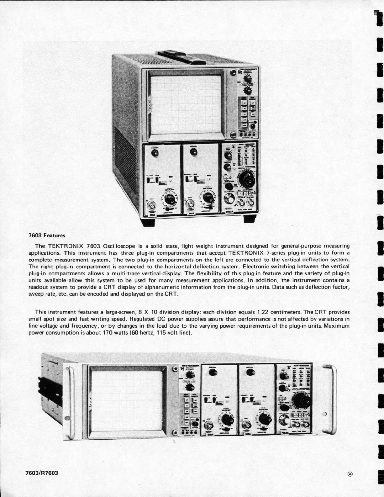
7603Features
T
heTEKTRONIX
applications.Thisinstrumenthasthr
completemeasurementsystem.The
Therightplug-incompartmentisconnectedtoth
p
l
u
g-incompartments
un
its
available
readout
sweep
system
rate,
etc
.
7603
Oscilloscopeisαsolid
allowsαmulti-trace
allowthissystem
ovi
de
to pr
be
encodedanddisplaye
can
R
α
C
eeplug-incompartmentsthatacceptTEKTRONIX7-series
twoplug-incompartmentsonthe
verticaldisplay.The
e
to
b
Tdisplayofalphanumeric
for
used
dontheCR
state,
light
weight
ehorizontaldeflectionsystem.Electronic
flexibilityofthis
many
measurement
informatio
T
.
instrument
leftar
app
lications.1
fromthe
n
designed
e conn
ectedtothever
l
p
u
η a
plug-i
n
g-i
dd
n
units.Datasuchasdeflection
forgen
eral-purpose
plug-inunitstoform
tical
deflectionsystem
switchi
featureandthevarietyofplug-i
n,theinstrumentcon
itio
betweenthe
ng
measuri
vertical
tains
factor,
ng
α
.
n
α
Thisinstr
smallspotsizeand
linevoltage
p
owercons
7603/137603
ument
featuresαlarge-screen,8Χ
fastwr
andfrequency,or
ump
tionisab
out
itingspeed.RegulatedDC
by chan
170
watts (60 h
10 d
ivision
display;eachd
powe
r s
upp
lies
gesintheloaddue tothevaryi
ertz,
115-voltline).
ivisio
n equ
als1.22
assureth
atper
formance
ngpowerrequirementsoftheplug-i
centimeters.TheCRTprovides
isnot
affecte
dbyvar
n un
its.M
iationsin
axi
mum
Page 5

General
To
effectively
usethe7603,the
operationand
capa-
bilitiesoftheinstrumentmust
be kn
own.This
section
d
escribesthe op
erationoft
hefront-and
rea
r-p
anelco
n
t r
ols
and connectors
and
givessimp
lifie
d
a n
d
generaloper
ating
information.
O
p
eratingVoltage
T
hisinstrument
is
desig
ned
for
operationfromα
p
owerso
urce
with
its
neutral
at
or near
eart
h
(ground)
potential
with
αseparate
safety-eart
h
conductor
.
Itis
not
intended
for
operation
from
two
ph
asesofα
multί-ph
ase
system,oracrossthelegsofα
single-phase,thr
ee-wire
system
.
T
h
e
7603
can be op
eratedfrom
eitherα110-voltor
α
220-voltnominal
line-voltage
source,Inaddition,
t h
ree
operating
ranges
canbeselected
withineac
h nominal
line
voltage
source.Thevoltage-selectorjumperontheRectifie
r
b
oard(see
Fig.1-1)
allows
selectionoftheoperating
voltage.To
conver tthe
instrument
f rom
oneregulati
ng
range toanothe
r ,fir
stdisconnectthein
strument f romt
he
p
ower
source.T
hen,slide
outth
epowerunitasdescri
bed
inthe Maintenance
section.Removethevoltage-selecto
r
jumperan
d
r
e-installitontheset
of pinswhichrep
resent
thedesire
d
r
egulating range.Selectαrangewhich
is
centered
aboutthe
averagelinevoltage
to
w
hichthe
inst
rumentistobe connected
(see
Table
1-1)
.
TA
BLE
1-1
R
egulatingRange
andFuse
Data
Ungrou
nded(Lin
e)Br
own
Blac
k
G
r
o
unded(Neu
t
r
al)Bl
ue
Wh
ite
Pins
R
egulatingRange
G
rounding(Earthing)
G
reen-Yellow
G
r
een-Yellow
Selecte
d
110-volts
n
ominal220-voltsnominal
L
O
W
ME
D
Hl
L
ineFuse
REV.D,
OCT.197
6
O
PER
ATI
N
G
INST
RU
CTIO
N
S
PRELIMINA
RYINFO
RM
ATIO
N
W
A
RNIN
G
90to110
volts
99to121
volts
108to132
volts
3.2Α
slow-
blow
180to220
volts
198to242
volts
218to262volts
1.6Α
slow-
blow
Section1-7603/R7603
Operators
PowerCordConductor
Identificatio
n
Conducto
r
Ι
Colo
r
Fig.
1-1.Locations
of
voltage-selectorjumper,sp
are
jumper,and
A
LTFUSEin
powe
r u
nit
(7603
shown)
.
To
co
nve
r t f rom110-voltsto220-voltsnominallin
e
voltage,
or vice versa,removethe
voltage-selectorjumper
andreplace
it
withthesp
arejumper
(storedonpin
s
adjacentto
voltage
selector
area).Thejumper
s a recolo
r -
co
dedtoindicatethenominal
voltage
forwhichtheyare
inte
nded;
brownfor110-volt
nominal
operatio
nandred
for
220-volt
nominalop
eration.Changethelinefusetoprovi
de
p
r
otectionforthe
selectedn
ominalline
voltage.Usethe
fuse
locatedintheALTFUSE h
olderontheRectifier
b
oard(see
Fig.1-1)orsee
Table
1-1
for
value.
Also,
c
han
ge
theline-cordplugto
matc
hthe power-sou
rcereceptacle
or
useαsuita
blea
dapter
.
Alternate
Colo
r
The
7603
isdesignedtobe
use
d with αthr
ee-wire
AC
p
ower
system.If
αth
ree-totwo-wire
adapterisused
to
connectthisinstrumenttoα
two-wire
ACpowersystem,
be
Page 6

O
p
e r
ating
Instructions-7603/R7603
Operators
s
ure
to connect
t
he g
r
oundleadof
thea
dap
ter
to ea
r t
h
wit
h
r
eal-time
amplifiers,
time-base
units,orcombinations
(gro
und
) .Fail
ure
to
complete
the g r
o
und system
mayallow
of
these
.Useofspecial
purposeplug-i
n u
nits
may
result
i
n
t
hech
assisofthis
inst
rum
enttobe
elevate
dab
ove
ground
d
ifferent types
of
displays,
whicharedefined
i
n
t
h
e
p
otential
and p
oseαs
hock h
azard
.
instructionmanuals
for
these
specialunits.Thefollowing
termi
nology
willbe
use
dthroughou
t thismanual
.
O
p
erating
Temperature
T
h
e
7603
canbe
operate
dwh
ere
the ambient
ai
r
tem
pe
r
ature
is
b
etwee
n
0°C
and+50°C.This
i
nstrument
ca
n be
stored
inambient
temperaturesbetween
-55°C
a
nd
+75°C.Afterstorageattemperaturesbeyon
d
t
heop
e r
ati
ng
limits,
allow
t
he ch
assis tempe r
aturetocome with
i
nthe
op
eratinglimitsbeforepowerisapplied
.
The7603iscooledby
con
vectionair
flow
through
t
he
instrument.Com
po
nen
ts
whic
h
requir
e
themost
cooli
ng
are
mountedexternallyonαheatrad
iatorat
therear
.
A
dequ
ate
clearancemust
be pr
ovided on
all
sidestoallow
h
eat
to
b
e
d
issi
p
atedf r
o
m
t
h
e
instrument.
Donotbloc
k or
r
estrict
the
air
flow
thro
ug
hth
eholesinthe
cabinet or
t
he
h
eatrad
iatoronthe
rear
.
M
aintain
theclearance pr
ovide
d
by
thefeetont
he b
otto
mand
allow
about
two
i
nch
es
clea
r a
n
ceonthetop,
sides,
a
nd
r
ear
(more
ifpossible)
.
T
he
R
7603iscooled
b
y
ai
r
dr
aw
nin
t
hroughth
e
ai
r
filterontherea
r
p
aneland
b
low
n
out
throug
hthe
h
oles
on
t
he
r
ight
side.A
deq
uate
clearancemust
be p
rovidedat
these
locations.Allow
at
least
oneand
one-half
inches
clearan
ce
beh
i
ndthe
air
filte
rand
at
least
one
i
nch
on
the
r
ight
side.
OperatingPosition
Αbale-typestandismounte
d onthe b
ottomof
this
inst
rum
ent.
This
standpermits
the
7603
tobe
tilte
d
up
a
bou
t10°
fo
r
mor
e
convenient
viewing
.
General
DISPLAY
DEFINITIONS
AlternateMo
de
Α
time-sharingmethodofdisplayingtwo
o
r
mor
e
signals
withα
single cathode-ray
tubebeam.C
ha
nn
el
switchingis
se
que
n
tial
andoccursatt
he en
dofeach
sweep
.
C
h
oppedMod
e
Α
time-s
h
aring
method
ofdisplayingtwo
o
r
mor
e
signals
withα
si
n
gle
cat
ho
d
e-ray
tubebeam.Channel
switching
is
sequen
tial
andoccursatα
ratedetermine
d
by anintern
al
clockgenerator
(choppingrate)
.
Single
Trace
Χ-Υ
ΝΟΤΕ
See
Simplified
O
p
erating
Instructions
in this
section
forset-up
informationtoobtain
eac
h
of
thefollowing
displays
.
7
1
ι
ι
ι
a
nd
o
ne
sweep.
Αdisplay
of α
singleplot
prod u
ce
dbyo
ne
vertical
signal
Α
t
he
rm
al
cutouti
nth
is
instrument
provides
thermal
Α
d
is
p
lay
of
two
p
lots
produce
d b
y
two
vertical
signals
pr
otectio
n andinterrup
ts
t
he
p
owerto
the
inst
rum
entif
and
o
n
e
sweep
.
theinternal
temperature exceedsα
safe
operating
level
.
P
ower
isautomatically
restore
dwhenth
e
temperature
r
et
urn
stoα
safe
level
.
O
p
eratio
nin
confined
a
r
eas
o
rin
DelayedSweep-
Single
Trace
closeproximitytoheat-producing
i
n
st
rumen
ts
may
cause
thet
he
r
mal
c
u
touttoo
penmor e
frequen
tly
.
Αdisplay
of α
singleplotproducedbyonevertical
signal
and αdelayedsweep.
Two
sweeps
areusedto
pro
d
uceth
is
d
isplay;thesweeps
are operating-ίthα de1α
y
ίπΗ
/delaye
d
relationshi
pwh
ere
one
sweep
(i
den
tifiedasthe
d
elayi
ng
sweep)delays
the
sta
r t
of
the
secondsweep
(identifiedas
the d
elayedsweep)
.
DelayedSweep-
Dual
Trace
R
ackmount
ί
ng
Α
d
is
p
layoftwoplots
pro
du
ced by combiningtwo
vertical
signals
and
αdelaye
d
sweep.
Two
sweepsare
use
d
Instructions
anddimensional
drawin
gs
fo
r rackmou
nting
toproduce
this
display;t
he sweep
s
are
operati
ng with α
t
h
eR7603
are
locatedin
Sectio
n 3 of t
h
e
o
pe
r
ators
ma
nu
al
.
d
elaying/delaye
dr
elationship.
E
ac
h
vertical
signalis
d
isplayedagai
n
st
the
d
elayedsweep.
Αplotoftwo
variables,neitherofwhichrepresents
Thefollowingdefinitionsdescribethe types
ofdisplaystime.Χreferstot
he
h
orizontal
axis
a
nd
Υ
r
eferstothe
whic
h can
b
e
obtai
ned
withα
7603
Oscilloscope
syste
m
ve
r
tical
axis
.
Ο
ι
ι
ι
Page 7

General
PLUG-IN
UN
ITS
CONTRO
L
S
ANDCO
NNE
CTORS
T
h
e
7603
is
designed
to
accept
up
to
three
TEKTRONIX
7-seriesplug-in
units.Thisplug-in
feat
u
re
allows
α
variety
of display
combinationsand
also
allows
selectionof b
andwidth,
sensitivity,display
mode,
etc.t
o
meet
the
measurement
re
qu
ireme
n
ts.In
a
dd
ition,itallows
the
oscilloscope
systemto
beex
pa
nd
ed tomeet future
measurementreq
uirements.Theoverall
capabilitiesofthe
r
esultant
system
are
in
large
p
art
determine
d
b
y
the
characteristicsoft
h
e plug-inselected
.For
complete
infor-
mation on
p
lug-ins
available
for
use
wit
hth
is
instrumen
t,
see
the
curre
n
t
Tektronix,
Inc.catalog
.
Plug-in
Installation
To
install
α p
lug-inunit
i
ntoone of the
plug-in
compa
r
tments,
align
the
slots
i
n
t
h
e
to
pand
b
ottomoft
h
e
plug-in
wit
hthe associated g
uid
e
railsinthe
plug-in
comp
artment
.
Pushth
e
plug-i
n
u
nit
firmly
into
the p
lug-i
n
compa
r
tment
untilitlocks
into place.To
removeαplug-in,
pull
the
release
latchon
the p
lug-i
n to d isengage
it
and
pull
theunit
outoft
h
e
plug-in
compartment
.Pl
u
g-inunits
can
be
removedor
installe
d
without t
urn
ing
off
t
h
e
inst
rum
entpower.
Itisnotnecessary
that
all
of
the p
lug-incompartments
be
filledto
operate
t
h
e
inst
ru
ment;the
only
plug-in
units
n
ee
de
d
are
those
requiredfo
rth
e
measurement
tobemade
.
However,atenvironmental
extremes,
excess
radiationmay
b
e radiated
into
oroutofthis
instrument throug
hth
e
ope
n
plug-in
compartments
.
B
lan
k
plu
g-inpanels
are
available
fromTektronix, Inc.t
o
cove
rth
e
unused
compart
men
t
;
or
derTEKTRON
IXPartNo.
016-0155-00
.
Whe
n
t
h
e
7603
is
calibratedin
accorda
nce wit
h
t
h
e
calibratio
n pr
oce
dur
e
given
in
the
service
ma
nu
al,
the
v
ertical
andhorizontal
gain are stan
d
ardized.
This
allows
cali
brated
p
lug-i
n
un
itstobe
changed
fromone
plug-i
n
compartment
to
anotherwit
h
out
recalibration.
However,
the
basic
calibratio
n
of
the
individualplug-inunits
shoul
d
b
e check
e
d
w
h
en
t
h
ey
are
installedin
this
system
to
verify
theirmeas
u
rement
accuracy.See
the
operating
instr
u
ctions
sectio
n
of
the
plug-in
unit
instructionmanual
for
verifica-
tionproce
dur
e
.
Special
purpose
p
lug-i
n
un
its
mayh
ave
specific
rest
r
ic-
tions r
ega
rd
ing
t
h
e
plug-in
com
pa
r
tments
i
nwhich
t
h
ey
can
beinstalled.
This
inform
ationwill
be giveninthe
instruc-
tio
n
manu
al
fo
r
t
h
ese
plug-inunits
.
Operating
Instructions-7603/137603
O
perators
T
h
e
ma
j
orcontrols
foroperationoft
he
7603
are located
on
the
frontpaneloftheinstrument
.Figs.1-2
and
1-3
pr
ovide α b
rief
d
escriptionof each
control
andconn
ecto
r
.
M
oredetaile
d
operating
inform
ationis
give
n und
erGeneral
Operating
Information
.
General
O
PER
ATING
CHECKOUT
T
h
e
following
Ope
r
ati
ngCheckou
t
providesαmeans
of
verifying
instrument
operatio
nand
b
asic
calibration
with-
outremoving
the
coversorma
k
ing
internal
adjustments
.
Sinceitd
emonstrates
the
useofall
controls
andconnec-
tors,itcan
alsobe
used
toprovi
de b
asic
trainingonthe
operationof
this
instrument.If
r
e-calibrationof
the
7603
appearstobenecessary,
see
the
Cali
br
atio
n pr
oce
dur
e
i
n
Section3 of
t
h
e Service
manual.If
re-calibrationof
α
p
lug-in
u
nitisindicated,
see
theinstruction
man
u
al
fo
rth
e
app
ropr
iate
plug-inunit
.
Set-
Up
Information
1 .
Set
thefront-panel
controlsasfollows
:
INTENSITY
Co
un
te
r
cloc
k
wise
F
OCUS
M
idrange
BEAM
F
IND
ER
R
elease
d
G
R
ATIC
ULE
ILLUM
Asdesired
VER
TMOD
E
LEF
T
TRIG
SO
UR
C
E
VER
TMOD
E
P
O
WER
Pushedin
2
.
Co
nn
ect
the
7603toα
powersource
whichmeets
the
voltage and
fre
que
n
cy
requ
irementsofthis
instrument.The
ap
plied
voltage
shoul
d b
enea
rth
e centerof
the voltage
ra
n
gemarkedon
the
rea
rpan
el
(see
O
pe
r
atingVoltage
i
n
t
h
is
sectionforinformationon converting this
instrument
from
one operating
voltage
to another)
.
3.Install
TEKTRONIX
7A-series amplifierunits
i
nto
b
ot
hth
e
left
and
right
verticalplug-i n
compartments
.
Installα713-series
time-baseunit
into thehorizontal
compartment
.
NOTE
4
.
Pull
the P
O
WER
switc
h
to
turn the
instrumenton.
L
ate
r
prod
u
ction
ofrackmou
n
t
oscilloscopes
are
pro-
Allow
several
minutes
warmu
p b
eforeproceeding
.
νίde
d
with
su
pportp
osts
between
t
he
individualplug-
i
n
compart
m
ent&
Αpostorposts
m
u
st
be
removedif
α
muldw
ίdthplug-inisto
b
e
installed.
To
r
emove
α
5.Setbathverticalunits
forαdeflectio
n factor of
two
p
ost,
un
fastenthe
screws
that
secureitat
thetop a
nd
volts/divisionand
cen
te
rth
e verticalpositioncontrols.Set
bottom
of
theplug-in
housing
.
bot
h ve
r
tical
units
forAC
i
nput
coupling
.
REVC,JUL
197
8
Page 8

OperatingInstru
ctio
n
s-7603/R7603
Operators
I
FUN
CTIONS
OFCO
NTROL
S
AND
CO
NNE
CTORS
Fron
tPan
el
L
ight
: Indicatesthat
thepower
switchisona
nd
t
hatt
he
inst
rum
entisconn
ectedto αlinevoltage
so
u
rce
.
1
. INTENSITY-Cont
rols brightn
ess of
the disp
lay.Control
is
inop
erativewhenhorizontalcomp
art
m
entisvacant
.
8.CALIBRATOR-Calibrator
outputpinjacks(4V,0
.4V,40
mV,ground) .Positive-going
pulse
o
r
DC
voltage
selecte
d by
2
.
RE
ADOUT-T
urnsonthereadout
d
isplayandcon
t r
ols the
changinginternaljumper.
R
epetitio
n rateisapproximately
one
readoutin
te
n
sity
.
k
ilohertz.
3
.FOC
US-Provides a
dju
stment
forop
ti
mumdisplay d
efinition.
4.GR
ATIC
ULEILLUM
-Co
ntrols
gratic
u
le
illumination
.
LEFT:
Sign
alsfromplu
g-inun
itin
leftver
ticalcompar
tment
aredisplayed.
5.BEAM
FIND
ER-Whenpressed,th
e scan
is
limitedto
withi
n
t
heg
r
aticulearea
.
ALT:Signalsfrom
plug-inunitsin boththeleftand
righ
t
verticalcompartments
a
redisplayed(dualtrace).Display
switchedbetwee
n
verticalplug-inun
its
aftereachsweep.
6.TRIGSOUR
C
E
-Selectssour
ce ofinternaltrigge
r
sig
nalfo
r
t
hetime
base
plu
g-inin
t
heho
rizontalcompar tment
.
ADD:Signals
fromplug-inunitsin
bot
htheleft
a
ndright
verticalcompartments
a
realgebraicallyaddedandth
e sumis
LEFT:
T
hetr
iggersignalisobtaine
dfromtheplug-i
nunit in
displayed
on
t
h
eCRT.
the
leftver
tical
com
partm
entonly.
CHOP:Signals
fromplu
g-i
n unitsinboththeleft
a
ndright
VER
TMOD
E:Triggersignalau
tomatically
follows
the ver
tical
verticalcompartments
a
r
edisplayed(dualtrace).Th
e d
isplay
is
d
isplay
exce
p
t
in
C
HOPandADD;the
nthetr
igge
r
signalisthe
switched b
etweenver
ticalplug-inun
its
at ap pr
oximatelyone
algebraicsumof
the
signals
f romtheleftand
rightver
tical
m
egahertzrate
.
compartments
.
RIGHT:
Sign
als
f romplug-inunitinrightvertical
compart-
RIGHT:T
hetr
iggersignal isobtainedfromth
e
p
l
u
g-i
nu
nit
in
ment
isdisplayed.
therigh
t ve
r
ticalcomp
artment
only
.
10.Ca
meraP
ower(NotLabele
d
)
-T
h
ree-pinconn
ector
on
C
R
T
7
.PO
WER-
b
ezel
providespowe
routput
(+15
V)
.
R
eceivesremotesin
gle
swee
p
r
eset
signal
fromcompatible
camera
systems,andαgro
und
pin
Switch:Con
trols
powertothe
inst
rument.
connection
.
9.VERTMODE
-Selects
vertical
mode ofoper
ation.
Fig.
1-2
.
Front-panelcon
trolsand
connectors
.
ι
ι
ι
Page 9
ιιιαιsιιιιιιιι
s
ιιιιιιιιιιι
ιι..,
.
ss
ιιιιιιιιιιι
s
ιιι
ιι
. . ,
ιιαιsιιι
s
ιιιιιιιι
ιι~ιιΡ~ι.ιιsιιιιssι
sιs
ιιιιι
sι
IN
WATTS
FORT)
ι
λ
f
AMPS
ΙΕΕΑΧΙ
F
USE
ι
AT
THEY.Ν
Κτ
0
32ΑSLOW 100-ΙΜ
RANGE
SS
READY
OUT
(7503P
=16ASLOW
200-24ΟΥRANGE
REMOTE
ERASEIN11613
7623ALTERNATE
FUSE INSIDE
131
ΥΕΡΤ
S1G
0UT
ΜΑΙΝ
'ΑUXILIARY
1
Υ
ΕΜΤ
Ζ
AXIS
IN
1
ΙLΑΥ
+6
ΑΤΕ
O
UT
ΥΙΟΥΜΑΧν500
Ω
POSITIVE
SIGNA
.
DECREASES
INTENSITY
}SAW7007N
THIS
INST61MEN7Ι$
CONNECTED
ΟμΤ
ιFOR
0
υ
Τ 10%
JUMPERSι
INSIDEFREDUENCY50ΤΟ
400
Χε
11,ο
ω
R
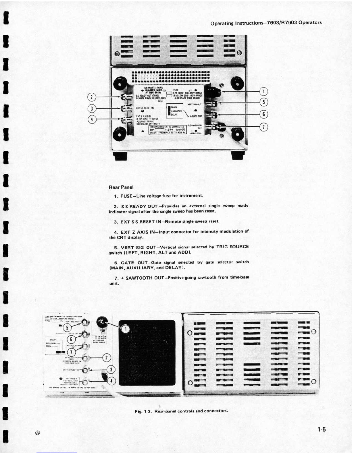
earPanel
1.FU
SE-L
ine voltage
fuse
for
instrument
.
2.SSRE
ADYOU
T-
Provides an external
si
n
gle
sweeprea
dy
indicatorsignal
afterthesin
gle
sweephas b
eenr
eset
.
3.ΕΧΤ
SSRES
ETIN-Remote
single
sweepr
eset
.
4.ΕΧΤ
Ζ
AXIS
IN-input
connectorfor
i
nten
sitymodu
lationof
theCR
Tdis
play
.
5.VER
T
SIGOUT-Vertical
signal
selecte
dbyTRIGSOUR
C
E
switc
h
(LEFT,RIGHT,ALTandADD)
.
6.GATEOU
T-Gate
signal
selecte
d b
y gate
selectorswitc
h
(MAIN,
AUXILIARY,
andDEL
AY)
.
7.+
SAWTOOT
HOUT-P
ositive-goi
ng
sawtoothf romtime-base
unit
.
F
ig.1-3.Rea
r
-panelcont
rols andco
nn
ectors
.
O
p
erating
Instr
u
ctions-7603/137603
O
pe
r
ators
"
~
ω
qN
W-191111111110
"INOWIRM
!
οΛΙΝ
"
2-100
NNIF
Γ7
111111
1111411%
!-
1
Ε
ir"
V
e
Υ
^
OW
No
Page 10

O
p
erating
Instructions-7603/R7603
Operators
6.Set
thetime-baseunit
forα swee
p
r
ateofone
14
.Press
theRIGHTbutton
of
the
VER
TMOD
E
millisecond/divisio
ninth
e
auto,
internal
triggermode.
switch.Remove
thecalibrator
signal
from
theleft
vertical
and
connectitto
the
right
vertical.The
display
amplitude
shouldbe
fourdivisions
within0
.12division.Note
the
exact
display
amplitu
d
e
for
the next
step.
7
.
Advance
t
h
e
INTENSITY
control
un
til
t
h
e
traceisat
t
h
e
desire
d
viewing
level
(nea
r
midr ange)
.
Advance
the
RE
ADOUT
u
n
til
t
he
r
eadout
displayisat
the
desire
d
viewing
level
.
8.Connect
the4Vcalibrator
pin-jackto
the
inputof
the
left
verticalunit
withαBNCtopin-jac
k ca
b
le
(supplie
d
accessory)
.
Graticule
Illuminatio
n
11
.Rotate
theGRAT
I
LLUM
control
throughout
its
ra
nge
an
d
n
otice
that
theilluminationof
the
graticule
lines
increasesasthe controlisturned
clockwise
(most
obvious
with
tintedfilter
installed).Set
thecontrolsothe
graticule
lines
are
illuminatedas
desired
.
15.Α
correct
display
i
n
both
steps
12 and14
indicates
that
the
7603
Vertical
DeflectionSystem
and
t
he ve
r
tical
plug-i
n
un
its
are
cali
b
rated.
If
t
h
e
displaysnote
d
p
reviously
are bot
h
ou
tside
the
given
toleranceinthe
same
directio
n
(i.e.,highor
low),
the
Vertical
Gain
or4
Volts
calibrato
r
a
djustm
ent
probab
lynee
d
s
r
e-a
dj
ustment.Otherwise,
chec
k
t
h
e
calibrationof
the
vertical
plug-inunits
.
Triggeri
ng
ί
ι
ι
16
.
N
otice
that
thepositio
n co
ntr
olofonly
theright
verticalunithasaneffectonthe
positionof
the
display
.
P
ositio
nth
e
displaytothe
lowerhalfofthegraticule.Set
DisplayFocus
b
othvertical
units
forα
deflectionfactorof
two
volts/
9.A
dju
st
the
FOC
US co
ntr
ol
forα
s
h
arp,
well-defined
divisio
n
.
Connect
calibratorsignaltobothvertical
units
by
display
ove
rth
e entire
trace
length.Ifαproperly
focuse
d
u
sing
α dualinput
coupler
.
display
cannot be ob
tainedwit
hth
e
FOCUS
control,
the
internal
Astigmatism
adjustment
must
be
re-set;see
the
17
.Press
t
h
e
A
L
Tbuttonofthe
VER
TMODEswitch.
Calibrationsectionof
the
Service
manual
.
N
otice
that
two
traces
are d
isplayedon
the
CRT.The
to
p
trace
isproduce
d b
y
the
left
vertical
unit
a
ndthe
b
otto
m
traceisproduce
d
b
y
the
r
ight verticalunit.Set
the
swee
p
r
ate
to 50
milliseconds/
d
ivision.Notice
that
t
he disp
lay
Trace
Alignment
alternates
betwee
n
t
h
e
left
andright
verticalunits
after
eac
h
sweep.
T
urnth
e
sweeprate
switc
hthroug
hou
t
its
10.Disconnect
thein
put
signal
andposition
the
trace
r
a
n
ge
.Notice
that
the
display
alternates
betweenve
r
tical
wit
hth
e
left
verticalunitpositioncontrol soitcoincides
un
itsatall
sweeprates
.
wit
hth
e
centerhorizontal
lineofthe graticule.If
the
trace
is
not paralleltothe
centerhorizontal
lineofthe
graticule,
see
T
r
aceRotatio
nadju
stment
procedure
inCalibratio
n
section
of
the
servicemanual
.
18
.Press
theCHOP
bu
ttonof
the
VER
TMODEswitch.
Tur
nth
e swee
p
r
ate
throughout
itsrange
.Notice
that
α
du
al-trace
displayispresentedat
all
sweeprates,butunlike
ALTb
othverticalunits
are
displayedon each sweep
i
n
α
time-sharingmanner
.Retur
nth
e
sweep
rate
to0.5
m
illisecond/division
.
19
.
P
ress
the
ADD
bu
ttonof
the
VER
TMODEswitch.
The
display
sho
u
l
d b
B
fou
r
d
ivisions
inamplitude
.Notice
that
the
positionco
n
trolofeitherverticalunitmoves
the
display
.
R
et
urntheVER
TMODEswitchto
LEF
T
.
ι
Vertical
Deflection
System
20.Center
the d
isplayοηthe
CRTWί
t
hth
e
left
vertίcα
1
un
it
positio
n co
n
trol.Disconnect
the
i
npu
t
signal
fro
mth
e
12.Connectt
he
4
V
calibrato
r
sig
n
altothe
i
npu
t
r
ig
h
t
ve
r
ticalunit
input
conn
ector.Sequen
tiallypress
all
of
connectorof
the
left
vertical
unit
wit
htheBN
Ctopin-jac
k
t
heVER
TMODEswitc
h
bu
ttons
.
N
otice
t
h
at
α
stable
cable.Set bot
h vertical
un
its
forα
deflection
factor
of
o
n
e
displayisobtaine
d
in
all
positio
n
s
of
the
VER
T
M
OD
E
volt/
d
ivisio
n
.
The
displayamplit
u
d
eshoul
db
e fou
r
switc
h
(straight
line
i
n
RIG
H
T
position)
.
divisions
.Note
the
exact
display
amplit
ud
e forstep15
.
21
.
Pr
ess
the
LEF
T
button of
the
T
RIGSOURCE
13
.Notice
that
the
positioncont
r
ol
of only
t
h
e
leftswitch.
Again,
seque
n
tially
press
all
of the
VER
TMOD
E
verticalunithasaneffect
on the
positionof
t
he disp
lay
.
bu
ttons.Notice
that
the
displayisagain
stable
inall
P
ositio
nth
e
displaytotheupperhalfofthegraticule
.
positions,asi
nth
e
previousstep
.
Page 11

ι
ι
ι
ι
ι
ι
ι
ι
22
.Press
theRIG
HTbutton oftheTR
IG
SOURCE
28
.
P
ress
and h
ol
dth
e
BEAM
F
I
NDER
switch.N
otice
switch.Sequentially
pr
ess
alloft
he
VER
TMOD
E b
uttons
that
t
he disp
layisreturnedto
t
he viewi
n
g
a reain
andnotice
t
hat
α
stabledisplay
cannot beobtaine
din
any
co
mpr
essed
form
. Inc r
ease
the
vertical
andhorizontal
position.
This
isbecauset
he
r
eisno
i
nput
signal
connecte
d
deflectio
n factors
until
thedis
p
layisr e
duced to
about
two
to
the right
verticalunit.R
et
urntheTR
IG
SOURCEswitc
h
d
ivisions
vertically
and
h
orizon
tally
(w
henthe
h
orizontal
to
VER
TMODE.
R
emove
cali
brato
r
signal
from
left
u
nitisoperatedinthe
time-
base
m
ode,
changeonly
the
verticalunit
and
connectitto r
ight
verticalunit
.Repeat
d
eflectionfactorof
thevertical
unit).Adjust
theposition
steps
20
to
22.T
he t
r
igger
signal
will
come
fro
m
righ
t
con
t r
olsoft
he disp
layedverticalunit
and
thetime-
base
vertical
.When
t
heLEFTbutton
is
pressedofthe
T
R IG
unit to cen
te
rthe
compresse
d disp
lay
about
thecenter
li
nes
SOURCE
switch
t
h
e d
isplayisnot
stablebecause
there
is
of
the
graticule.R
elease
the
BEAM
F
INDERswitch.Notice
no
in
pu
t
signal
connected to
theleft
vertical.R
eturn
t
he
t
hatthe display
remai
n
s
withi
nthe viewi
n
g area
.
TR
IG
SO
UR
CE
switch to
VER
TMODE.
H
orizontal
DeflectionSystem
23.P
ositio
nth
e
startoft
he
swee
p
to
the
left
graticule
line
wit
hthetime-base
u
nit
p
ositioncontrol
.
24.Co
nnect
α10Χ
p
r
obe
to
theinputoft
he
r
ig
h
t
vertical
unit.Set
ther ight
vertical
unit for α d
eflectio
n
factor
of10volts/
d
ivisionand
set
t
he
VER
TMODEswitch
toRIGHT
.
Set
t
he time-
b
ase
unit
forαswee
p
r
ate of
five
milliseconds/
d
ivision.
25.Co
nnectthe
probetip
to α
line-voltage
source.The
d
isplayshoul
d sh
ow
three
complete
cycles
ove
rthe
10
d
ivisions
within0.3d
ivision.
Α
correct display
indicates
that
the7603Horizontal
Deflection
System
and
the
time-baseunit
are co
rr
ectly
calibrated.Ifthe disp
lay
is
outside
t
he given
tole
r a
n
ce,
eithe
rthe
7603
o
rthe
time-b
aseunitneeds
to
be
recalibrated.Referto
t
he
Calibrationsectio
n ofthe
Service
manual,
andto
t
he
time-base
unit
ma
nu
al
fora
dju
stmentprocedure
.
REV
Β
,
JUL
1978
ΝΟΤΕ
T
hisstepisbasedon an
accur
ate
60-Hertz
line
frequ
ency.F
or ot
h
er
line
frequencies,
this
procedure
willneed
to
be c
han
ged
accordingly
.
Z-Axis
Input
Operating
1nstructions-7603/
R
7603
Operato
rs
29.If
an
external signalisavaila
b
le
(five
voltspeak
-to-
pea
k
min
imum
at
twomegahertz
orless),
the f
unction
of
theΕΧΤ
Ζ
AXIS
input
canbedemonst
r
ated.Connect
t
he
external
signaltobot
htheinpu
tofthe
right
verticalunit
and
t
he
ΕΧΤΖAXIS
connectorwithtwo
BN
C
cables
and
α
B
NCΤ
co
n
nector.Set
the
VER
TMOD
E
switc
h to
R
IG
HT
and
set
t
he ve
r
ticalunit
fo
r α
d
eflectio
n
factorof
two
volts/divisio
n
.
Set
thetime-baseunit
forα
swee
p
rate
whic
h
disp
lays
several
cycles
of
thesignal.Adjust
the
a
mp
lit
ude of
the
signal
generato
r
un
til
intensitymodulationis
visi
b
le
on
t
he dis
p
lay.T
he p
ositivepeaksofthe
waveform
s
h
oul
d
b
e
b
la
nk
ed
out
and
t
he
n
egative
peaks
i
nten
sified.N
otice
that
thesetting
of
the
INTENSITY
co
n
t rold
etermines
the
amo
unt ofinten
sitymodulatio
n
t
h
at
is
visible
.
30.Disco
nn
ect
thesignal
fro
mthe
ΕΧΤ
Ζ
AXIS
connector,but
leaveitco
nnected tothe
right
verticalunit
i
npu
t.C
hec
kth
at
p
eak-to-peak amplit
ude ofthe
d
isplaye
d
signalisfourdivisions
maximum.
31.This
completes
t
he
O
p
eratingCh
eck
out
procedure
for
the7603.Inst
rum
entoperations
not
explai
ned he
re,
or
operations
whic
h
needfurth
e r
expla
nation
arediscusse
d
und
e r
General
O
p
erating
Information.
26.Disconnect
theprobe
from
t
helin
e-voltage
source
and
t
h
eright
verticalunit
andco
nnect
t
he
probe
to
the
left
verticalunit.Set
t
he
VER
TMOD
E
switch to
LEF
T
SI
MPLIFIE
D
O
PER
ATI
NG
INST
RU
CTIONS
and
set
thetime-base un
it
forαsweeprate
of0.5
m
illiseco
nd/d
ivision
.
T
he
following
informationis
pr
ovided to
aid
i
n
quick
ly
o
b
taining
thecorrect
setti
ngforthe
7603
controls
to
B
eamFinder
prese
n
tαd
isplay.The
o
perator
shoul
d
b
e
familiar
wit
hthe
complete
fun
ctionandope
r
atio
n ofth
is
instrument
as
27.Set
thed
eflectio
n
factorof the
left
verticalunit
to
d
escribedelsew
he
r
e
i
nth
is
sectio
n befo
r
eusing
this
0.1volt/division.
N
otice
thatαsq
uare-wavedisplayisnot
pr
oce
dur
e.F
or
detaile
d op
e r
ating
i
nfo
r
matio
n
fo
rthe
visible,
si
nce
t
he d
eflectionexceeds
the scan a
r
ea of
the
p
lug-i
n un
its,
see
the
inst r
uction
manuals
fo
rthe a
pp
lica
b
le
CRT
.
u n
its
.
Page 12

O
per
ating
Instructions-7603/117603
Oper
ato
rs
Si
n
gle-Tr
aceDisplay
Dual-Trace
Display
T
he
followingpr
ocedure willprovide
α
displayofα
T
he
followingpr
ocedure
will
provide
α
d
isplayoftwo
single-trace
vertical
unit
agai
nstonetime-baseunit.For
single-trace
verticalunits
against
one
time-base
unit
.
simplicityofexplan
ation,thevertical
unit is
installe
dinthe
left
verticalcompar
tment.The
right
vertical
compartme
n
t
canbeusedifthepr
ocedureischanged
accordi
n
gly
.
5.Connectthesignaltotheinputconnectorofthe
verticalunit
.
6.Setthe verticalunitfor
ACinputcoupling and
calibrateddeflectionfactors .
7.Setthe
time-base
unit
for
auto
mode,in
ter
n
al
triggeringatα
calibrate
d
sweep
rate
of
one
millisecond/
d
ivision.
8
.
AdvancetheINTEN
SITYcon
t rolun
til
α disp
lay
is
visible.(Ifnodisplayisvisible
wit
hINTEN
SITYatabout
midran
ge,press
and holdthe
BEAM
FINDER
switc
hand
a
dj
ust
the
vertical
d eflectio
n
factorun
tilthe d
isplay
is
reducedin
size
vertically;thencenterthe co
mpr
esse
d
disp
lay
with
vertical
and h
orizontalpositioncontr
ols
;
r
eleasetheBEAMFINDER.)AdjusttheFOCUScontrol
for
α
well-defi
ned disp
lay.A
dju
stReadoutINTEN
SITY
for
the
desired
viewinglevel
.
9.Setthe
verticaldeflectionfactor
and
vertical
positio
n
control
forαdisplaywhichremains
withinthegraticule
areaver
tically
.
10.If
necessary,
setthetime-base
triggeringcont r
olsfor
α
stabledisplay
.
11.A
djustthetime-baseposition
controlsothedisplay
b
eginsattheleft
edgeofthegraticule.Setthe
time-base
sweep
rate
todisplaythedesire
dnumberof
cycles
.
1.Install
7A-series
ve
r
ticalunits
inbothvertical
plug-i
n
compartments
.
1.Installα7A-seriesver
ticalunitin
t
heleft
vertical
compartment
.
2.Pr
essthe
LEF
T
buttonoftheVERTMODE
switch.
2.P
ressthe
LEFTbuttonoftheVER
TMODEswitch.
3
. Installα713-series
time-baseunitinthehorizontal
compartment
.
3
. Installα713-series
time-baseunitinthehorizontal
compartment
.
4.Pr
esstheVER
TMOD
E
bu
ttonoftheTR
IG
SOURCE
switch.
4
.
P
ress
the
VER
TMOD
E
bu
tto
n oftheTR
IG
SO
UR
CE
switch.
5.Connectthe
signaltot
hei
np
ut
co
nn
ectorsofth
e
verticalun
its
.
6.Setthever
ticalunits
for
ACinputco
up
lingand
calibrateddeflectionfactors
.
7.Setthe
time-baseunit
fo
r
au
to
mode,in
ternal
t r
iggeringatα
sweep
rateofonemillisecond/divisio
n
.
ι
ι
ι
ι
ι
8.AdvancetheINTEN
SITY
control
un
tilαdisplay
is
visible.(If
no d
isplayisvisible
withINTENSITY
at
midran
ge,pressand h
oldBEAM
F
I
NDER
switc
hand a
dju
st
verticaldeflectionfactorun
tildisplay
isreduce
d
in
size
vertically;t
hen
center
compresse
d disp
lay
with
verticaland
horizontalpositio
n con
trols;releasethe
BEAM
FIND
ER
switch.)
SettheFOCUS
con
trolforαwell-defined
display
.
9.Set
t h e
leftver
tical
unit deflection
factor
for
α
displayaboutfou
rdivisionsinamp
lit
ude.Adjusttheleft
verticalpositio
n con
trol to
moveth
isdisplaytothetopof
t
he graticule
area
.
10.Pr
ess
t
heRIGHT
b
uttonofthe
VER
TMODE
switc
h
.
11.SettheRIGHT
verticalun
itdeflectionfactorforα
d
isplayabout
fo ur
divisionsinamplitude(ifdisplay
cannot
b
e
located,use
BEAM
FINDER
switch)
.Positionth
is
displaytothe b
ottomofthegr
aticuleareawit
htheright
verticalunit
positio
n con
trol
.
12.Pr
esstheALTorCHOPbu
ttonoftheVERTMODE
switch.
Αdual-tracedisplayofthesignalfromthe
left
ι
Page 13

ι
verticalandright
verticalplug-inunitsshouldbe
p
resente
d
NOTE
-i
nform
ationon
c
h
oice ofdual-
ontheCRT.(For
-trace
mode,
seeVe r
tical
M
odeinthissection
.)
Some
78-series
time-base
units
h
ave
provisions
for
am
p
lifier
operation
in
theΧ-
Υ
mode;seeΧ-
Υ
o
p
erationinthis
section
fo
r
detailsofoperation
in
13.If
n
ecessary,
adjustthe
time-basetr
iggeringcontrols
this
ma
n
ner
.
forαsta
b
ledisplay
.
1
.
Install
7A-seriesamp
lifierunits
inbot
hthe
left
14.A
dju
st
thetime-basepositionco
ntrolsothedisplay
vertical
an
dthe hor
izontal
com
partments.
b
eginsat
t
he
left
edgeofthegratic
ule.
Setthetime-base
sweep
rate
forthedesiredh
orizo
n
taldisplay
.
2
.
P
resstheLEF
Tbutto
noftheVER
TMODEswitc
h
.
DelayedSwee
p-Single
Trace
T
he
following p
rocedure
willprovi
de α
delaye
d
swee
p
d
isplayofα
single-trace
ve
r
ticalunit
.
1
.
Followthecomplete
proced
ure
give
n under Si
n
gle-
Trace
Displays
.
5
.
Setbothamplifierun
its
for
ACinputcouplingand
cali
b
rate
d d
eflectionfactors
.
2
.Besurethetime-base
u
nit
installedinth
ehorizo
n
tal
com
p
artmentisα d
ual
time-base
with d
elaying/delaye
d
.
6.Advance
theINTENSITYcontrolun
til
αdisplay
is
capabilities
visible.(If
no
d
isplayisvisible,
p
ress
andhold
BEAM
FINDER
switc
h and a
djustt
he
deflectionfacto
r s
ofbot
h
3.Followth
eproce
dure
givenintheinstructio
n
man
ual
amplifie
r
un
itsuntil
d
isplayisreduced
i
n
size
both
forth
edualtime-b
aseunitto
obtainαdelaye
d
-sweep
vertically
and
hor
izontally;t
hen centercom
p
resse
d disp
lay
d
isplay
.
wit
hthe
positio
n con
t r
ols;release
theBEAM
FIND
ER
switch.)Adju
st
t
he FOCU
S con
trol
forαwell-defi
ned
display
.
DelayedSwee
p-DualTr
ace
G
ENER
A
LOPER
ATI
NGINFORM
ATIO
N
T
h
e
followingproce
durewillprovi
de αdelayed-sweep
displayoftwo
single-tracever
ticalunits
.
IntensityCon
trol
The
settingoftheI
NTENSITY
con
trolmay
affectthe
correct
focusofthe
display.Slightre-a
dju
stmentofthe
1.F
ollowthecomp
lete
proce
d
ure
given
underDual-
FOCUScontrol
may
b
enecessary,whenthein
te
n
sity
level
Trace
Dis
p
lay
.
ischanged.Toprotect
theCRTphospho
r
;do
notturnt
he
INTENSITY
co
n
trolhig
he
r t
han
n
ecessary
toprovide
α
satisfacto
r
ydisplay.Thelight
filters
reducetheobserve
d
2
.Besurethe
time-base
unit
installedinth
ehorizontal
lig
htou
tput fromthe
CRT.Wh
e
n
usingthese
filters,
avoi
d
com
p
artmentisα
dual
time-base
u
nitwithdelaying/delaye
d
ad
vancing theINTENSITY
con
troltoα
settingthat
may
capabilities
.
b
ur
nthe ph
osphor.Wh
enth
ehighestinten
sitydisplay
is
desired,
removeth
e
filters
and useonlytheclea
r
faceplate
p
rotector(perman
entlyin
stalle
d behi
nd
b
ezel).Apparent
3
.
F
ollowthe proced
ure
giveninthein
struction
manual
tracein
tensity
can
alsobei
mpr
oved
i
n
such
casesby
fo
rthe
d
ual
time-baseunit
to
ob
tainαdelayed-swee
p
reducin
g theam
b
ient
light
level
oru
si
n
g α
viewi
nghood.
d
isplay
.
Also,be
careful
thattheINTENSITY
co
n
t rolisnot
set
too
h
ighw
hen ch
angingthetime-base
u
nitsweepratefromα
fast
to
α
slow
sweep
rate,orwhe
n c
h
a
ngingtotheΧ-Υ
mode
of
op
eration.Theinstru
mentincor
poratesprotectio
n
Χ-Υ
Display
ci
r cuit
rywhic
h autom
atically
reduces
thedisplayinten
sity
to
α
lowerlevelwhenthetim
e-
b
aseun
it is
settoα
slow
Th
e
following
procedure
willprovi
de anΧ-
Υdisplay
sweepr
ate.This
reduces
t
hedanger
ofdamagingtheCR
T
(one
signal
versusanother
rat
he
rthan
against
time)
.
ph
osphoratth
ese
slower
sweeprates
.
Operati
ng
Instructions-7603/137603
O
pe
r
ators
3
.
Conn
ecttheΧ
-sig
naltotheamp
lifierun
it
i
nthe
h
orizontal
compartme
nt.
4.Co
nn
ecttheΥ-signaltothe a
mp
lifieruniti
nthe
left
vertical
com
p
a rtment
.
Page 14

OperatingInstructions--7603/R7603
Operato
rs
Dis
p
lay
F
ocus
L
ight F
ilter
T
he
F
OCUS
control
allows
a
dj
ustment
fo
r
b
estdefini-
Thetintedfilterprovi
ded
with
t
he
7603
m
inimizes
light
tionof
the
CRTdisplay.Th
e
R
eadout
intensity
s
hould b
e
reflections
fromthe
faceofthe
CRTtoi
mpr
ove
con
t r
ast
t
urne
d
on,
w
hen a
dj
usting
t
he
F
ocus
co
n
trol.Slig
ht
when
viewing
thedisplayunder h
ighambient
light
condi-
r
e-a
djustmen
t
of
this
control
m
aybenecessary as
t
he
tions.This
filter
s
h ould
b
eremoved
for
wavefo
rmph
oto-
disp
lay
conditionscha
n
ge.If
αprope rlyfocused
display
graphs
o
rwhen
viewinghig
h
w
r
iti
ng
r
atedisplays.To
cannot beob
tai
ne
d
with
t
h
e F
OC
UScon
t r
ol,
theinternal
remove
thefilter,
loosen
the
two
screws
onthe
r
ight
sideof
Astigmatism
adjustme
ntmu
stbe
re-set;see
theCalibratio
n
t
h
e b
ezel
and remove
thebezel
.Remove
thetinted
filter
;
sectionoftheservice
manual
.
leave
the
clea
r
p
lastic
faceplateprotecto
r
i
n
stalle
dand
Gratic
u
le
replace
t
he b
ezel.Thefaceplateprotector
shouldbe
left
i
n
placeatall
times
toprotect
theCRT
faceplate
from
The
graticule
of
the
7603ism
a
rked onth
e
inside
of
t
he
scratches
.
I
I
faceplate
of
t
h
e
C
R
T,ρr
ονίdίη
g accurate,
.-
measurements.T
he g
r
aticule
isdivi
dedi
n
to
eight
vertical
and
tenhorizontal
d
ivisions.Each
division
is1.22
centimete
r s s
qu
are
.
1
η ad
dition,
eac
h
major
d
ivisionis
divi
dedi
n
to
five
m
inordivisions.Thevertical
gain an
d
hor
izontal
timi
n
gofthe p
lug-i
n u
nits
are
calibratedto
t
he
graticulesoaccurate
measurementscan be
made
from
t
he
CRT.T
he
illuminationofthe
graticule
lines
canbe
varied
with
t
heGR
ATIC
ULE
I
LLUM
control
.
Two
ty
pes of
crt
g
rat
ί
cules
have
beenusedin
some
Tektronix
oscilloscopes.One
gratίculehas
0%
and
100%rί
setimerefe
rence
p
oints
that
are
separatedby
6
vertical
grat
ίcule
divisions
.The
ot
he
rgr
at
ίcule
h
as
the0%and100%rί
setime
referencepoints
separate
d
by 5ver
tical
divisions.In
your
manual,
illustrations
of
t
h
e
crt
face
o
r r
ί
setime
measurement
instructions
may
not
correspondwit
hth
e
graticule
markings
on
your
oscilloscope
.
Fig.
1-4shows
thegraticuleofthe
7603andd
efines
t
he
variousmeasurement
lines.Theterminologydefine
d
h
ere
willbeused
inall
d
iscussions
involvingg r
aticule
measure-
ments
.
N
otice
the
0°%o,
10%,
90%
and
100%markingsont
he
left
sideof
t
he g
r
aticule.These
markings
are pr
ovi
de
d
to
facilitate
rίsetimemeasurements.
F
irst
Cen
te
r
Ninth
vertical
vertical
vertical
line
line
li
ne
ΝΟΤΕ
ιοο
i
1:
9α
.
. .
. .
... .
.
Cente
r
i..~
.
horizontal
ι
i
Ι
li
ne
An
o
p
tional
meshfilterisavailable
fo
r
u
se
with
t
he
7603.This
filte
r
pr
ovides
shielding
against
radiated
EMI
(electro-magnetic
interfere
n
ce)
f r
o
mthe
face of
theCRT.
It
also
servesasα1ί
ght
filtertomake
thetracemore
visible
underhighambie
n
t
light
conditions.The
meshfilter
fits
i
n
placeoft
he
p
lastic
C
R
Tmas
k
and
thetintedfilter
.
B
eamFinder
ι
Th
e
BEAMFINDERswitc
h pr
ovides
αmeansof
locati
ng
α
display
whichoverscans
the
viewing
area
eit
he
rver
tically
orhorizontally
.When
theBEAM
F
I
NDER
switchispresse
d
andh
eld, t
he disp
lay
is
compresse
d withi
nth
e graticule
area
.Release
t
he
BEAM
F
IND
ER
switchto
ret
u
r
n
to
α
normal
d
isplay
.
To
locate
a
nd
rep
ositio
n an
oversca
nned
d
isplay, usethe
following pr
oce
dur
e
:
3.Adjust
thevertical
andhorizontal positio
n co
n
trols
to ce
nterth
e
display
about
thevertical
andhorizontal
cente
rlin
esofthe
graticule
.
4
.Release
the
BEAM
F
I
ND
ER
switch;
t
he disp
lay
shouldremai
n withinthe
viewing
area
.
R
ea
d
outMod
es
ί
ί
The c
har
acte
r s
of
therea
d out
d
isplay
a
r
e
writtenby
t
he
ιπ
. . .
.Ι. . . ..... ....~. . . . . . ..~. . ..~....:-....~..
.
C
R
Tbeamonαtime-sha r
e b
asis
with
sig
n
al
waveforms.T
he
ο.-
λ
__
R
eadout
systemop
erates
inαfree ru
nn
i
ng
m
odeto
randomly
inte
rrup
t thewaveformdis
p
lay
topresent the
ε
131ο-
ο5
r
ea
d
outcharacters.T
he
readout
system canαιs
οop
erate
i
n
α
GAT
ETR
IG'D
mode.
No
r
eadout
signal
isproduceduntil
after
the
swee
p
h
as
occ
urred.
In
thismode
thesweepmust
F
ig.1-4
.
Definitionofmeasurementlineson7603
graticule
.
run
to
h
ave
the
rea
dou
tdisplayed.
REVC,JUL
1978
1
.Press
andholdtheBEAMFINDERswitch.
2
. I
ncr
ease
the
vertical
andhorizontaldeflectionfactors
u
n
til
theverticaldeflectionis
reduced
to
about
two
d
ivisions
a
ndthe hor
izontaldeflectionisreducedtoabo
ut
fo
ur
d
ivisions
(t
he h
orizontaldeflectio
n
n
eedsto
be
r
e
d
ucedonly
w
hen
in
theΧ-Υmodeofop
eration) .
ι
Page 15

ι
DisplayPhotography
Αpermanent
r
ecordof
theCRTdis
p
lay
can
beobtai
ne
d
with an
oscillosco
p
e
camera
system.T
hein
structio
n
manuals
fo
rth
e
TEKT
RO
N
IX
Oscilloscope
Cameras
include
com
p
lete
instructions
fo
rob
tainingwaveform
ph
otographs.T
he
followingspecific
i
nfo
rm
ation app
lies
to
the7603
.
ι
ι
ι
ι
ι
ι
ι
ι
T
heCR
T
bezel of the
7603
pr
ovides
integ
ral
m
ounting
forα
T
EKTRON
IX
Oscilloscop
e
Camera.Thet
hr
ee pins
located
on
theleft
side of
the
C
R
Tbezel
co
nnect
p
owerto
compati
b
le
camera
systems
.
It
also receives
control
signals
f
r
om
T
EK
TRONIX
automatic
cameras
to
allow
came
ra-
co
ntr
olled
single-s
hot
p
h
otography(see
came
r
amanualfor
further
informatio
n
) .
V
erticalMo
de
L
eft
andRightMode.W
he
nthe
LEF
T
orRIG
H
T
bu
tton of
t
he
VER
TMOD
E
switchisp
ressed,
only
the
signal
f r
o
mthe
p
lug-i
n un
it
i
nthe
selectedcompartme
n
t
is
d
is
played
.
Alternate
M
ode.
T
heALT
positio
n of the
VER
T
MOD
E
switch
pro
d
ucesαdisplay
whichalternatesbetwee
n
t
he
p
lug-i
n
un
its
i
nthe
left
vertical
and
right
vertical
compart-
ments
witheac
h
sweepof
theC
RT
.
Altho
ughtheAL
T
mode
can
beusedatall
sweep
rates,
the
C
HO
Pmod
e
provides
αmo
r e
satisfacto
r
y d
isplayatswee
p
r
ates
b
elow
about20
milliseconds/divisio
n
.Att
hese
slower
swee
p
r
ates,
alte
rn
ate-mode switch
i
ng
becomes
visually
perceptib
le
.
T
h
e
TRIGSOURC
E
switchallows
selectio
n of
t
he
triggeri
ng fo
r
an
alte
r
natedisplay
.Whenthis
switchis
set
to
the
VER
TMODEpositio
n
,
eachsweepistrigge
red
b
y
t
he
signal
being
displayed
on
theCRT.This
provi
d
esαstable
d
isplayoftwo
unr
elatedsignals,but
d oes
not
indicate
t
he
time
relatio
nsh
ip
b
etween
the signals.In
eit
he
rthe
LEF
T
o
r
RIGH
Tpositions
of
theTRIG
SOURC
E
switch,thetwo
signals
are d
is
p
layed
showi
ngtru
e
time
r
elationship
.
H
owever,ifthesig
n
als
arenot
time-related,
the d
isplay
from
t
he plu
g-inunit
whichis
not
providi
ng
α
trigger
signal
will
ap
pear un
stable
on
theCRT
.
ΝΟΤΕ
Th
is
instrument
will
not operateinthe
ALT
mode
if
thehorizontal
plug-in
unitisnot
operatedin
t
he
time-base
mode
.
Operating
Instructions-7603/
R7603Ope
r
ators
rates
lower
t
han
about
20
m
illiseconds/divisio
n
,
or
when
eve
r
du
al-trace
single-s
hot phen
ome
na
a r
e tobe
displaye
d
.Atfaste
r
sweep
rates,
t
he chopp
ed switching
becomes
apparent
a
nd
m
ay
interfere
wit
hth
e
dis
p
lay
.
Correct
internal
trigge
r
ing
for the
CHOPmode
ca
n
b
e
ob
tained
in
any
of
t
h
e
three p
ositions
of
the
TRIG
SOURC
E
switch
.When
t
he
T
R
IG
SOURCE
switc
h
is
set
to
VER
TMOD
E
,
theinternal t
r
iggersignals
from
t
he ve
r
tical
p
lug-inunits
are
algebraically
addeda
ndth
e
time-
base
u
nit
is
triggered
from
theresulta
n
t
signal.U
se of
t
he
LEF
T
o
r
RIGH
T
t
r
igger-sourcepositions
trigggers the
time-
b
aseunit
on
t
he
internal
triggersignal
from
theselecte
d
verticalunit
only.This
allows
two
ti
me-r
elatedsignals
to
bedisplaye
d
sh
owi
ng
true
time r
elatio
nship
.However,
if
the
signals
a r
e
n
ot
time-related,
thedisplay
fr
o
mthe c
h
a
nn
el
whichisnot
pr
oviding
the
triggersignal
will
appea
run
stable.TheC
HO
P
mo
de can be
use
d to
compare
two
si
n
gle-shot,
t r
ansient,
or
ra
ndo
m
signals
whichocc
ur
withi
nthetim
e
interval
d
etermi
ned
b
y
the
time-base
un
it
(ten
times
selected
swee
p
r
ate).To
pr
ovidecorrect
triggering,
thed
is
p
lay
whic
h
pr
ovides
thetr
igger
signal
mustpreced
e
the
seco
n
d d
isplay
in
time.Si
ncethe
signals
show
true
time
r
elationship,
time-
d
iffere
nce
m
easu
reme
n
ts
can
be
ma
d
e
f romt
he
d
isplay
.
Algebraic
Ad
d
ition
.
T
he
ADD
p
ositio
n ofthe
VER
T
M
OD
E switch
can
b
eused to d
isplay
thesum
or d
ifference
of
two
signals,
for
common-mod
e
rejectio
n to r
emove
an
und
esi r edsig
n
al,
orforDCoffset(ap
plying αDCvoltage
to
one
cha
nnn
el
to
offset
theDC
com
po
n
en
t
of α
signalont
he
ot
h
er
channel).Theco
mm
on-mode
re
j
ection
ratiobetwee
n
t
he
verticalplug-i
n
compartments
of
the
7603isgreate
r
t
h
an20:1at50
m
egah
ertz.T
he re
j
ection
ratio
increases
to
100:1atDC.
Theoverall
d
eflection
factoron
theC
R
T
i
nth
e
ADD
modeistheresulta
n
toft
he algeb
r
aic
a
dd
itionof
thesignals
from
the
two
verticalplug-i
n
un
its
.
It is
difficult
to
d
eterminet
he voltage a
mp
lit
ude of
ther
esu
ltant
dis
p
lay
un
less
theam
p
lit
ude
of
thesignal
a
p
pliedto
oneof
th
e
p
lug-i
n
un
its
isknow
n
.Th
is is
p
articularlytrue
w
hen
t
he
verticalunits
are
settodiffere
n
tdeflectionfacto
r
s,
since
it
isnot
ob
viouswhic
h p
ortio
n ofthe
d
isplayisα
resultofthe
signal
applied to
eit
he
r pl
u
g-i
n un
it.Also, t
he
p
olarityand
r
epetitio
n
r
ate
of
t
he app
liedsignals
en
ters
into
t
he
calcu
lation
.
T
he followin
g
ge
n
e r
alprecautions s
houl
d
be observed to
Chopp
edM
od
e
.
T
h
e
CHO
Pp
osition
of
t
he
VER
T
pro
vide
thebestdisplay
w
hen usingthe
ADD
m
ode
:
M
ODEswitc
h
pr
o
d
uces α disp
lay
whic
h
is
electronically
switche
d b
etwee
n c
han
nelsatα
one-mega
h
e r
tz rate.In
1.Donot
excee
dthein
put
voltage
r
atingofthep
lug-i
n
ge
ne
ral, t
heCH
O
P
m
od
e p
rovides
t
h
e b
estdisplayatswee
p
un
its
.
Page 16

Operating
Instructions-7603/117603
Operators
2.Do
not apply
large
signalstot
heplug-ininputs.Α
d
isplay.Some
ofthe
713-series
time-baseunits
can be
goodruletofollow
is
not
to
apply
α
signalwhich exceeds
operatedasamplifiers
i
n addition toth
eirnormaluse as
anequ
ivalent
of
abo
u t
eight
timesthevertical
deflectio
n
time-
b
ase
generators
.
This
feature
allowsanexternal
signal
factors.For
example, withαvertical d eflectionfactor
of
toprovideth
ehorizontal
deflectionontheCRT.Formost
0.5volt/division,the
voltageapp
liedtoth
atplug-inu
nit
ofthetime-baseunits
wit
htheamplifierfun
ction,theΧ
s
h
oul
d notexceed4volts
.Larger
voltagesmay
resultinα
(horizontal)
signal
ca
nbe
connected
either
to an exte rn
al
d
istorte
d disp
lay
.
i
nputcon
nectoronthe
time-baseunitoritca
n be
routedto
the
time-baseunitthr
oug
htheinternal
triggering
system
(see
time-base
instr
u
ctionmanualfor
details).Ifthe
latte
r
3.Toen
sureth
e
greatestdynamic
rangeinthe
ADD
met
hodisu
sed,theTRIGSOUR
C
E
switches
mustbeset
so
mode,
settheposition
co
n
trolsoft
heplug-i
n un
itstoα
t
hattheΧ(hor
izontal)
signal
isobtaine
dfrom
oneoft
he
settingwhichwouldresulti
n α
mid-screendisplayifviewed
ve
r
ticalunits
andtheΥ(vertical)
signalisob
taine
dfr
om
i
ntheLEFTorRIG
HT
p
ositionsofthe
VERTMODE
t
heothervertical
unit.Thea
d
vantages
ofusingthein
ternal
switch.
trigger
system
to pr
ovi
d
ethe
Χ
signalarethatthe
attenuator
switchof
t
he
amplifierunitprovidingthe
h
orizontal
signaldetermines
t
he h
orizontaldeflection
4.Forsimilarrespon
se
from
eachchannel,
setthe
factor to
allow
full-
rangeoperatio
n andthe
plug-i
nun
itsdo
p
lug-i
n un
itsforthesameinput
coupli
ng
.
nothavetobe
movedb
etweencompartments
whenΧ-
Υ
operation
is
desired.
ί
ι
ι
ι
ι
Trigger
Source
Anothermethodofob
taini
ng an
Χ-Υdisplayistoin
stall
TRIGSOUR
CEswitc
h
allows
selectionofthe
T
he
internal
trigger
signal
forthetime-baseunit.Formost
an amplifierplu
g-inunitino
neoft
hehorizontal
plug-in
this
switchcanbe
settotheVER
TMODE
compartments
(chec
kam
p
lifier
unit
gainas
give
ninthe
cations,
applications,
p
osition.Th
ispositionisthe
most
convenient,sinceth
e
Pl
u
g-inin
structionmanual
to
obtain
calibratedhorizontal
internal
trigger
signal isau
tomatically
switc
hed
asth
e
d
eflectionfactors).This
methodprovidesthe
bestΧ-
Υ
VER
TMODE
switchis
c
hanged,or asthedisplay
is
display,particularlyiftwo
iden
ticalamp
lifierunits
are
electronically
switchedbetween
t
h e
left
vertical
andright
used,sin
cebot
htheΧand
Υinputsystems
willhaveth
e
verticalplug-i
n un
itsin
t
h
eALT
positionoftheVER
T
samedelay
time,
gai
nchar
acteristics,inputcoupling,
etc
.
MODE
switc
h
.Italsoprovides
α u
sable
trigger
signalint
he
Fo
r
further
informatio
n onobtainingΧ-Υdisplays,
seeth
e
ADD
orCHOPpositionsofthe
VER
TMODEswitch,sin
ce
plug-inunitmanuals
.
Also,the
referencebooks
listed
und
er
theinternal
triggersignalinth
esemodesisthealgebraic
Applications
pr
ovideinformation
onΧ-Υmeasurements
sum
ofthe
signalsapp
lie
d tothever
ticalplug-inun
its
.
andinterpretingt
he
r
esultant
lissajousdisplays
.
Therefore,the
VER
TMODE p
ositio
n ensuresthatt
he
time-baseunit
receivesαtrigger
sig
nalregardlessoft
he
VERTMODE
switc
h
setting,
withou
t t
heneedto
change
I
nten
sity
Modulation
the
triggersou
rce
selection.
Inte
n
sity
(Z-axis)modulationca
nbeusedtorelate
α
t
h
ird
item
of
electricalphenomena
to
t
hever
tical
(Y-axis)
If
correct
triggeri
ng
fo
r t
h
edesireddisp
lay
isnot
a
ndthehorizontal
(X-axis)
coordinates
with
out
affecti
ng
ob
tainedin
theVERTMODEposition,the
LEFTor
the
waveshapeofthedisplaye
d
signal.The
Z-axismodu
-
RIGHTpositions
canbe usedtoobtai
nthetrigger
signal
lating
signalap
plied
to
t
heCRTcircuitchangesth
e
fromeitherthe
left
verticalorright
verticalplug-i
nunit.
intensityofthedisplayed
waveformtopr
ovidethis
type
of
Theinternal
trigger
signalisob
tainedfromtheselected
d
isplay."Gray
scale"inten
sity
modulatio
n can beob
taine
d
vertical
compartment,whethert
heplug-inuniti
nth
at
b
y
applyingsignals
w
hichdo
not
completelybla
nkthe
compa r tmentis
selected
fordisplayontheCRT
ornot.If
d
isplay
.Largeamp
litu
de
signalsofthecorrectpolarity
will
theinternaltrigger
signalisob
tained
from
oneofthe
completelybla
nk
t
hedisplay;thesharpestdisplay
is
verticalun
its,buttheotherverticalunit is
selecte
d
for
providedby
signals
withαfast
rise
and
fall.Thevoltage
d
isplay,the
internal
trigger
signal
mustbetime-r
elatedto
amplit
uderequ
ired
for
visi
bletracemod u
lationde
pend
s
t
he disp
layedsignalinordertoobtainαtriggered(stable)
uponthesettingoftheINT
EN
SITY
control.A
two-volt
dis
p
lay
.
peak
-to-peaksignal
will
com
p
letely
bla
nkthedisplay
even
atmaximuminten
sity
levels
.Lowe
r
a
m
plitude
signals
can
be
usedto
only change
thet r
acebrightnessrather
than
Χ-ΥOperation
completelybla
nkthe d
isplay
.Negative-goi
ngmodulating
signals
increaseth
e
d
isplay
intensity
andpositive-goi
ng
1ηsomeapp
lications, it
isdesi
r able
todisplayone
signal
m
o
d u
lating
signalsdecrease
thedisplayinten
sity
.Useful
versus
another
(X-Y)
ratherthan
against
time(intern
al
i
nputfrequ
ency
rangeisDC
to
10
megahertz(i
nputvoltage
sweep
) .The
flexibilityoftheplug-inunits
available
for use
d
eratingnecessary above
two
megahertz).Them
axim
um
wit
hthe
7603providesαm
eans
for
app
lyinganexternal
i
nputvoltageshou
l
d belim
itedto10
volts
(DCpluspea
k
signaltothehorizontal
d eflectio
n
systemfo
rthistype
of
AC)
.
ι
Page 17

Timemarkersapplie
d
to
the
ΕΧΤΖAXISi
npu
t
V
oltage.Thecali
b
ratorp
rovides
accurateoutputvoltage
conn
ectorpr
ovide
α
d
irecttim
ereferenceont
he disp
lay
.
of
40
millivolts,
0.4volt,and4volts
atthethree
W
ithun
calibrated
h
orizontal
sweeporexternalhorizontal
front-panel
p
in-jackconnectors
into
h
igh-impedance
loads
.
mode operation,
t
hetimemarkers
provide
α
means
of
Out
pu
t
resistanceisapproximately 50
ohmsatthe40mV
read
ingtim
edir
ectly
f romthe
display
.
H
owever,ift
he
and
0.4Vpinjack s a
nd appr
oximately
450ohmsatth
e
4
V
marker s a r
e not
time-relatedto
t
hedisplayedwaveform,
α
pin
jack.
single-swee
pdisplayshou
ldbeused
(forin
ternal
swee
p
only)
to pr
ovideα
stable
dis
p
lay
.
C
urrent.
Α
40-milliampere,one-k
ilohertzou
tputcur
rent
isprovide
d
whe
nthe
optional
current-loop
accessory
(TEKTRON
IX
P
art
No.012-0259-00)
is
conn
ecte
d
R
asterDisp
lay
b
etwee
nth
e4Vpin-jackandground.This
output can
b
e
u
sedtochec
k
and
calibrate
current-measuri
ng p
robe
Α
raster-ty
pedisplay
can
be
usedto
effectively
increase
systems .
theapparent
swee
plength.Forthistype
of
d isplay,
t
h
e
t r
aceisdeflectedb
othverticallyandhorizontally
b
y
sawtooth
signals.This is
accomplishe
dinthe
7603
b
y
W
aveshape
.
T
h
e square-waveoutp
ut
signalofthecali-
installingα
713-series
time-base
unitin
one
of
thever
tical
b
ratorcan
beu
sedasα
referencewavesha
p
e
whenchecking
p
lug-incompa r
tments
.Normally,thetim
e-base unitinthe
or adjusting
theco
m
pen
satio
n ofpassive,hig
h
-resistance
verticalcom
partmentsh
ou
ldbe
settoα
slower
sweeprate
probes.Since
t
h esquare-wave
output
f rom
t
hecalibrato
r
t
hanthe
time-base
unit
i
n
t
he
h
orizontal
compartment;the
h
asαflattop,any
d
istortio
ninthe
displaye
d
waveformis
numberofhorizontal
traces
inthe
rasterdependsuponth
e
duetotheprobe
compensation.DCvoltage
output
is
also
ratiobetwee
nthe
two
sweep
rates.Information
can
b
e
availablebychanging
αjumperonthecali
br
atorboard;
see
d
isplaye
d onthe
r
asterusing
severaldifferent
met
hods
.
In
Fig.1-5
.
the
ADDposition
ofthe
VERTMODEswitc
h,thesignal
f rom
an
amplifierunitcanbe
algebraicallyadded to
t
he
verticaldeflectio
n
.Wit
hthismethod,the
vertical
signal
Signals
Out
amplitudeon
theC
RTsh
ouldnot exceedthe
d
istance
Vertical
Signal.T
heVER
T
SIG
OUTco
nn
ector
b
etweenth
e hor
izontal
linesofthe
raster
.Anothermethod
of
dis
p
layinginform
ationonthe
rasteristo
usethe
ΕΧΤ
Ζ
P
rovidesαsam
pleofthe
verticaldeflection
signal.T
he
AXISinputto
provide
intensitymodulatio
noft
he disp
lay
.
so
ur ce of
t
he outputsignalisdetermi
ned
bytheTRIG
Thistype
of
rasterdisplay
could beuse
d
to
provideα
SO
URCE
switch.Thesou
rce
will
follow
t
he
setti
ng ofthe
television-typedisplay.Complete
informatio
n on
operatio
n
TRIG
SO
URCE
switch.When
t
heTRIG
SOUR
CEisi
nthe
V
ERTMOD
Etheoutpu
t
will
followtheVER
TICA
L
u
si
ngtheZ-axis
feature
is
givenu
nde
rInten
sity
Modulation
.
MODEswitc
h exceptCHO
P,t
henthe
signals
a reADDED
.
Modulation
.
Theoutput
sig
n
als
are
LEFT,ALT,
ADD
andRIGHT.T
h
e
To
provideαstable
raster
d isplay, b
ot
h
time-baseunits
must
b
e correctly
triggered. Inte rnaltriggering
is
not
provided
forthetime-baseunitswhen
t
hey areinthe
vertical
compartments;externaltr
iggeri
ng
mustbe
used.
Also,blankingisnotprovi
ded
fro
mthe
time-baseunits
whe
nthey are
installedinαvertical
compa r
tment.Toblan
k
out
theretraceportio
nfromthetime-
b
ase
unitinthe
ve
r
tical
compartment,sp
ecial
co
nn
ectionsmu
stbemade
fro
mthistime-baseunittothe
b
lanking
networkofthe
7603.Ifthismodeofo
p
erationis
desirable,
con
tactyour
localTEKTRON
IX
FieldOffice
orrepresentative
for
specificinform
ation
on
ob
taini
ngblanking
withth
e specific
time-baseunit
being
use
dinthever
tical
compartment
.
Calibrator
Op
erating
Inst ru
ctions-7603/137603
Operators
General
.
The
inte rn
al
calibratorofthe7603provides
α
conven
ient
signal
source
forcheckin
g b
asic
vertical
gai
nand
fo
r
adju
sting probecom
pensationasdescribedinthepro
be
-
-=~
-
instruction
manual
.Inaddition,the
calibratorcan be use
d
asαconve
nientsignalsou
rce
forapp
licationto
exter
n
al
Fig,
1-5.Jump
e
r
locations
forDCand
one-kilohertz
Cali
br
ato
r
eq uip
ment
.
oper
ation(Calibrato
rboa
rd)
.
Page 18

Operating
Instructions-7603/R7603
Operators
output
signal
into50ohmsisabout25millivolts/divisionof
the
vertical
signaldisplayedonsystems
CRT.The output
signal
into1mego
hm
isabout0.5
volts/divisionofthe
vertical
signaldisplayedon
the
systems
CRT
.
+
Gate
.
The +
gate
connectorprovidesαsweep
gate
signal
thatisgenerate
d by t
h
e
timebaseplug-i
n
un
it.The
gate
selectorswitc
h
pr
ovides
three
gates
MAIN,
AUXI L
IARY
and
DELAY.Thedurationof
the
gate
pulse
isdetermine
d
by t
h
e
respective
sweep.A
u xiliaryand
Delay
gates
can only bepro
ducedby
d
ual
sweeptimebaseplug-i
n
un
its.The
amplitudeofthegate
signalisabout50millivolts
into50ohms
or10
volts
into1megohm
.
+
Sawtooth.The+sawtoot
h co
nn
ecto
r
pr
ovides
αposi-
tive
going
sampleofthe sawtoot
h f
romth
e
timebase
u
n
it
in
thehorizontal
compartment.The
rateofriseofthe
saw-
toothsignalisabout50millivolts/unit
of time
into50ohms
or1
volt/unitoftime
into1mego
hm
.
Un
it
of time
isdete
r
-
mi
ned
by the
time/division
switchof
thehorizontalplug-i
n
unit
.
The
followingbooksdescribe
oscilloscope
measurement
techni
queswhich
canbe
adapted
for
use
wit
hth
is
instrument
.
1-14
J
.
F.Golding,
"Measuri
n
g
Oscilloscopes",
Tra
n
satlantic
Arts,Inc.,1971
.
CharlesΗ.Rot
hJr.,"U
se of
theOscilloscope",
Α
Programm
edtext,
P
re
n
tice-Hall
Inc
.,EnglewoodCliffs,
NewJersey,
1970
.
REP
ACKAGINGFO
RSHIPMEN
T
ι
ι
ι
If
the
Tektronix
inst
rum
entistobeshippedto
α Tektronix
Service
Ce
nterforser
vice
o
r repair
,
attachα
tagshowing
:
owner(ωίt
h a
ddr
ess)
a
ndth
enameofαπ
individualatyou
r
firm
that
can
be
contacted,
co
mp
lete
inst
rum
ent
serial
numb
er
andαdescriptionof
the
se
r
vicerequired
.
Save
andre-
use
the
p
ackageinwhichyour
instrument
was
shipped
.Ifthe
o
r
iginalpackaging
isunfit
foruse
o
r
n
ot
available,repackage
the
inst
rum
entasfollows
:
1.Obtainα cartonofcorrugated
ca
rdboard
h
avinginside
11
Appl i
cations
dimen
sionsofno
less
than
six
inches
mor
e
tha
nth
e
The
7603
Oscilloscope andits
associate
d
plu
g-i
n
un
its
inst
rum
en
tdimensions;this
will
allow
fo
rcushion
ing
.
p
rovideαvery
flexible
measurement
system.The
εαρα
-
R
eferto
thefollowing
table
fo
rcarton
test
strengt
h
b
ilitiesofthe
overall
systemdependmainly
upon
the
r
equirements
.
plug-inunits
that
are
chosenfo
r
u
se
wit
hth
is
instrument
.
Specific
app
lications
fo
rth
e
individual
plug-inunits
are
2
.
Surroun
dth
e
instrument
wit
h p
olyethylene
sheeting
to
d
escribed
i
nth
e
plug-in
manuals.The
overall
system
ca
n
p
rotect
the
finishof
the
inst
ru
ment
.
also
be u
sedformany
applications
whichare
not
describe
d
indetail
eithe
r
inthism
anualor
i
nth
emanuals
fo
rthe
individualplug-i
n
un
its.Contact
your
local
TEKTRONIX
3
.
Cushion
the
inst
rumen
tonall
sides by
tightlypac
k
ing
F
ieldOffice or representative
for
assistanceinmaking
d
unn
age
o
r
uretha
n
e
foa
m
b
etweencartonand
instru-
specificmeasurements
wit
hth
is
instrument
.
ment,
allowing
three
inches on
all
si
des
.
4.Seal
carton
wit
hshipp
ing
tapeori
ndustr
ial
stapler.
SHIPPIN
G
CARTO
N
TE
STST
RENGTH
Joh
nD.
Le
nk,
"H and
bookof Oscilloscopes,
Theory,
and
G
r
ossWeight
(lb)
CartonTest
Strength(lb)
Application",Prentice-Hall
Inc
.,EnglewoodCliffs,
New
J
ersey,
1968
.
0-10
200
10-30
275
30-120
375
J
.
Czech,
"OscilloscopeMeasuring
Techniques",
120-140
500
S
p
ringer-Verlαg,
New
York,
1965
.
140-160
600
ι
ι
ι
ι
REV
.
Β,OCT
.
1976
Page 19

Many
of
them
easurement
capabilities
of
this
T
hisinstrument
will
meet
thefollowing
electrical
specifi-
instrument
aredetermine
d bythe
choiceofplug-in
cations
after
complete
calibrationasgivenin
Sectio
n 5.T
he
un
its.The
followingcha
r
acteristics
apply to
the7603
O
pe
r
ati
ngCheckout
p
rocedurewhichisgivenin
Sectio
n
1
Oscilloscope
on
ly.See
the
System
Specification
at
p
rovides
α con
venie
nt
m
ethod
of
check
ingin
strumen
t
th
e
endof
this
section
for
specificationsoft
he
p
erformance
with
outmakinginternalchecksoradju
st-
complete
system.
ι
ι
ι
ι
ι
ι
ι
ι
Information
giveninthismanualapp
liestot
heR7603
Oscilloscope
also,
unlessoth
erwiseind
icated.TheR7603
is
electrically
identicaltothe7603,
but
it is
adaptedfo
r
mou
ntingi
n α
standa
rd 19-inchrack.Rack
mounting
instructio
n
s a
nd
αdimensionaldrawingfortheR7603
are
giveninSection3.
Deflectio
n F
actor
B
etween
Compartments
L
ow
FrequencyLinearity
B
an
d
width
StepRespon
seRisetime
Isolatio
n
betweenV
e r
tical
Compartments
DelayLi
ne
ChoppedMod
e
Rep
etitionR
ate
Ο
i
Characteristic
S
PE
CIFICATIO
N
VER
TICA
LDEFLE
CTIONSYST
EM
W
ithin1%
.
P
erformanceRe
quiremen
ts
Ι
SupplementalIn
formatio
n
Compatible
withall
7000-series
p
l
u
g-i
n
u
nits
.
0
.1
d ivision
orless
compressionor
expan
sionofαcenter-screen
2 d
ivisio
n
signalwhen positionedanywh
ere
vertically
withinthe graticulearea.
See
systemsp
ecifications
for7000-series
instruments.
See
system
specificationsfor
7000-series
i
nstruments.
At
least
100:1fromDCto10O
MHz
.
1
MHz
within20%
.
Sectio
n
2-7603/R7603
Ope
rator
s
ments.T
hefollowing
electricalch
aracteristics
a
p
ply
over
an
am
bienttemperatu
rerangeof0°C
to
+50°C,
exce
p
t
as
ot
h
erwiseind
icated.Warmuptime
for
give
n
accuracyis20
mi
n
utes
.
ΝΟΤΕ
P
ermits
viewingleading
edgeoftrigger
signal
.
Page 20

Specification-7603/R7603
Operators
Time
Segment
FromE
ach
Com
pa
rtm
en
t
Difference
In
Delay
Betwee
n
Vertical
Compartments
V
ertical
Dis
p
layMod
es
TriggerSo
urce
Deflectio
n
F
actor
2-2
Cha r
acteristic
C
ha
r
acteristic
C
ha
r
acteristic
Fastest
Calibrated
Swee
p
R
ate
LowFrequency
Li
n
earity
Ph
aseShift
Betwee
nThe
Vertical
andHorizontal
A
mp
lifiers
FrequencyRes
p
onse
Bandwidt
h
(8divRefere
n
ce)
VER
TICA
LDEFLE
CTIONSYST
EM
(con
t)
0.4to0.6
μ
s
.
HOR
IZONTA
LDEFLE
CTIONSYST
EM
5 n
s/div
.
P
erformance
Requir
ements
TRIGGERI
NG
Perfo
rm
anceRequirements
P
erformance
Requirements
Compatible
with
all
7000-series
plug-i
n
un
its
.
0.1div
orless
compressio
n orexp
a
n
sio
n
ofαcenter-scree
n 2
div
sig
n
al
w
hen
positio
ned
anyw
he
r
e horizontally
with
i
n
thegraticule
area
.
Less
t
han 2° f
r
om
DCto35
kH
z
.
At
least
2
MH
z
.
0
.5nsorless
.
Su
pp
lemental
Information
LEF
T:Left
verticalunit
only
.
Selected
by
VER
TMOD
E
switch.
ALT:Dual
trace,
alternate
betwee
nver-
tical
units
.
ADD
:
Ad
de
d
algebraically
.
C
H
OP:
Dual
trace,
chopped betwee
nver
-
tical
un
its
.
R
IG
H
T
:Right
verticalunit
only
.
Sup
plemental Information
S
u
pp
lemental
I
nfo
r
matio
n
ι
ι
ι
ι
ι
ι
ι
ι
LEFTVER
T
:
Fr
om
left
vertical
only
.
Selecte
d b
y
TRIGGERSO
URC
E
switc
h
.
VER
TMODE:
Determine
d
b
y
vertical
mode.
RIGHT
VER
T
:Fro
m
righ
t
vertical
only
.
ι
ι
Page 21

Voltage
O
utput
Accuracy
+15°Cto+35°C
0°Cto+50°C
Current
Output
Acc
ur
acy
+15°Cto+35°C
0°Cto+50°C
R
epetitionR
ate
OutputResistance
40mV
and0.4
V
4
V
ι
Characte
r
istic
U
sef
ulInput
V
oltageVe
r sus
R
ep
etitio
n Frequ
ency
ι
ι
ι
i
ι
Ch
aracteristic
Ι
Performance
Requ
i rements
Ι
SupplementalInform
ation
W
aves
hape
ιPositive-goi
ngsqua r
ewave
or
DC
(DC
voltage
selectedbyinternal
jumper)
.
VoltageOutpu
tRan
ge
Sensitivity(Fu
llInten
sity
Ra
n
ge)
P
olarityofOperation
M
aximumInpu
tVoltage
InputResista
n
ce
Came
r a
Power(
Ρ1041atCRT
Bezel)
Pin1
-+15
V
Pin
3-sin
gle
sweep
r
eset
Pin5-grou
nd
40
mV,0.4V,and
4V.
I
Into1ΜΩ
loa
d
.
Within1%
.
W
ithin2%
.
40
mA
.
2Vpea
k to peak.
CALI
BR
ATO
R
E
XT
ERNALΖAXISINPU
T
PerformanceRequ
iremen
ts
2Vpeak
to
pea
k,DCto2
MHz
;reducing
to0.4Vpeak to p
eakat10MHz
.
Positive-going
signaldecreasesin
tensity
.
OUTPU
TS
Characteristic
Ι
Performance
Requirements
S
p
ecification-7603/
R7603Op
erators
W
ithin2%
.
W
it
h
o
p
tio
n
alcu
rrentloopaccessory
(012-0259-00)
co
nn
ectedb
etween
4
V
W
ithin3%.
pinjac
k and g
round
pinjack
.
A
ppr
oximately1kH
z
.
A
ppr
oximately50Ω
.
A
pp
roximately
450Ω.
S
up
plemental
Information
10V(DC
to
peak
AC)
.
A
pp
r
oximately
500Ω.
S
upp
lemen
tal
Information
2-3
Page 22

S
p
ecificatio
n
-7603/137603
Operato
rs
C
haracter
Size
M
odesof
Operation
C
haracteristic
P
erformanceRequirements
Supplemental
Information
CathodeRay
TubeType
Τ
7400
.
Graticule
Characteristic
Adjustable
Triggere
d
after
sweep
Type
I
I
nternal
and
illuminated
.
Area
Ι
8Χ10div
.
Standard
1
1div
equals1.22cm.
Option
4
1
1
div
equals1cm
.
C
HAR
ACT
ERGENER
ATO
R
Free-run
independent
of
sweep
DISPLAY
(CRT)
and
OPTIONS
Option
6
1
d
iveq
uals1
.22cm
(Spectrum
~
Analyzer)
.
Phosphor
Standard
Ρ
31
Option 8
P11
of Ρ7onrequest
.
Beam
Finder
Limitsdisplay
to
within
graticule
area
I
when
BEAM
FINDER
switch
isactuated
.
Photographic
Writing
Specifications
Phosphor
Standard
Option
4
PerformanceRequirements
Ι
Su
p
plemental
Information
q
ι
ι
Selected
by
internal
READOUT
mode
switch
.
1
ι
ι
ι
r
ι
ι
ι
ι
ι
C53
Camera
(f
1.9lens
Ρ
31
100
d
iv/μs180
cm/μs
P
olaroid'film
type
107(3000
ASA)
.
1:0.85
Image-to-Object
Ρ
11
140div/μs260cm/μs
W
ithout
film
fogging
techniques
.
-Ratio)
1
Registered
t
rademark
Polaroid
Corporation
.
2-
4
Page 23

Specification-7603/R7603
Operators
P
O
WER
SOURC
E
Ch
aracteristic
Performan
ceRequirements
S
upp
lementalInformation
L
ineVoltage
R
anges
110Vnominal
100V±10%
.
110V±10%
.
120V±10%
.
220Vn
omi
n
al
200V±10%
.
220V±10%
.
240V±10%
.
L
ineFrequency
50
to
400Hz
.
M
aximumPowerConsumption
170W,1.9Α
.
(115VAC
;60
H
z)
Fuse Data
110
V
line(F
1000)
3
.2
Α
slow
blow
.
220Vline(F1000)
1.6Α
slow
blow
.
+130
VSupply(F855)
0
.15Αfastblow
.
ι
ι
ι
ι
ι
ι
ι
ι
VER
T
SIGOU
T
Char
acteristic
Ι
P
erformanceRequirements
Ι
Su
pp
lementalInformation
See
systems specifications
for
7000-series
instrume
n
ts
.
V
ertical
Signals
LEF
T,
R
IG
HT,ALT,
and
ADD
.
SelectedbyTRIGSOURCEswitch.
Gai
n
Into50Ω
25mV
/div
.
Into1ΜΩ
0.5V
/div
.
±20%
systemCRTto
VERTSIGOUT.
5nsorless
.
R
isetime(Into50Ω)
A
b
errations
Centering
SIGNALSOUT
t1
div
systemCRTto
VERTSIGOUT.
(1 .5Vinto1ΜΩor75mV
into
50
Ω
.)
Ou
tputResistance
950Ωwithin2%.
+GATEOU
T
Gate
Signals
MAIN,
AU
XI LIA RY, and
DELAY.
Selected
b
y
Gate
selector
switc
h
.
O
utp
ut
Into50Ω
0.5V
within
10%
.
Into1Ma
10Vwithin
10%
.
Ο
2-
5
Page 24

Specificatio
n
-7603/R7603
Operators
Operating
Altitude
2-6
O
p
erating
C
h
ar
acteristic
P
erforman
ceRe
qu
irement
Ι
S
upp
lemental
Info
r
mation
R
isetime(into50Ω)
OutputResistance
+SAWTOOTHO
UT
Out
put
I
nto50Ω
Into1ΜΩ
O
utpu
tResistance
Characteristic
Ι
I
nformation
Characteristic
This
instrument
will
meet
theelectrical
characteristics
givenint
he
P
erfor
ma
n
ceRequirement
columnof
the
Specifications
over
the
following
environmental
limits
.
TemperatureRange
N
on-operating
Non-operating
Transportatio
n(p
ackaged
instrume
nt,withoutplug-i
n
un
its)
q
ualifies
underNational
Safe
T
r ansit
testproce
dur
e
1Α,
CategoryΙΙ.
Char
acteristic
Ventilatio
n
SIGNALS
OUT
(cont)
ENVIR
O
NMEN
TA
L
PH
YSICAL(cont)
ΝΟΤΕ
Finish
0
°
Cto+50°C
.
-550Cto+75°C
.
15,000
ft
.
Test
limit
50,000ft.
Information
available
foruse
withthisinstrument,
seetheTektronix,Inc.catalog
.
2Referencedto
Time/Div
setting
.
7603
Ove
r
allDim
en-
sions(m
eas
u
redat
maximum
p
oints)
H
eight
W
idt
h
Le
ngth
PH
YSICA
L
H
eight
N
et
W
eight
(i
nstru
ment
only)
R
7603
Overall
Dimen-
sions
(measuredat
maximumpoin
ts)
W
idt
h
Safe
operating
temperature
main-
taine
d b
y
convection
cooling
.
L
engt
h
(7603)or
forced
air
cooling
(R7603).A
u
tomatic
resettingther-
malcutou
tprotects
inst
rum
ent
N
etWeig
ht
from
overheating
.
(i
n
strumenton
ly)
STANDARD
ACCESSO
RIES
20
ns
or
less
.
950
Ω
within2%
.
50mV/
un
it time2within15%
.
1V/unit
time2within 10ο/ο.
950
Ω
within2%.
Anodized
aluminum
front
pan
el
.
P
aintedcabinet
.
12.0in(30
.4
cm)
.
8
.7
in(22.0cm)
.
22
.7 in
(57
.6
cm)
.
30lb
(13.6kg)
.
Information
5
.25in (13.4cm)
.
19.0i
n (48
.5
cm)
.
21
.5 in
(62.0cm)
.
30lb(13.6kg)
.
1
ι
ι
ι
Standard
accessoriessu
ppliedwit
h
t
he7603
are
givenintheMecha
n
icalPartsList
illust
r
ations.Foroptional
accessories
ι
Page 25

ι
ι
A
mp
lifier
Plug-in
U
nit
16
7Α17
ι
1
T
he ban
dwidthofαvertical
p
lug-inused
in
the
ho
r
izontal
compartment
is2MHz
exceptfo
rthe7Α
22
whichhasα bandwidthof850kHz.T
heΧ-
Υphasesh
ift
b
etween2
simila
runitsis2°at35kHz.
Max
Time
P
erformance
Swee
p
T
r
iggeri
ng
Base
F
eature
R
ate
FreqRan
ge
7Α12
7Α15
Α
7Α18
7Α19
7A22
7
Β
52
71371
71392
TIME
B
ASEPLU
G-INS
Delayed
Swee
p
&
Ι
5 ns/divΙDCto
100
MH
z
Ext
Amplifie
r
DelayingSweep
15ns/divΙDC
to
100
MH
z
Delaye
d
&
Mixed
Ι
5 n
s/
d
ivΙDC
to
100
MHz
Sweeps
Delaye
d
&
M
ixe
dI5ns/
d
ivIDCto100
MHz
Sweeps
Delaye
d
Swee
p
s&Ι5ns/div
Ι
DCτο200
MH
z
E
xt
Amplifie r
Delayi
ng
Swee
p
15 ns/divΙ
DCto200
MHz
Display
Switching
15
ns/div
ι
DCto250MHz
7600-S
ERIE
S
SYST
EMSPECIF
ICATIO
NS
V
ertical
Syste
m
Specificatio
n
-7603/
R7603Ope
r
ato
rs
ΕΧΤ
CA
L
ΙΝΤCAL
ΙΝΤCAL
SIG
OU
T
Probe
BW
Ι
Τ
,
0to50
°
C15 to35°
C0 to50°
C
BW
Τ
,
I
n
tegral
100
MHz
3
.5ns
2%
3%4%
60
MHz
5.9ns
N
o
ne
2%3%4%
55
MHz
6
.4ns
Ρ
6053
85
MH
z
4
.2ns
3%
4%5%
55
MHz
6
.4
n
s
N
on
e
1
.5%
2
.5%
3
.5%
55
MHz
6
.4ns
Ρ
6055
80
MHz
4.4π
s
1
.5%
2
.5%
3
.5%
45
MHz
7.8ns
Ρ
6021
50
MHz
7
.0ns
2%
3%4%
40
MHz
8
.8ns
Ρ
6022
85
MHz
4
.2ns
2%
3%4%
50
MHz
7
.0ns
N
one
3%4%5%
50MHz
7
.0ns
Ρ
6053
65
MHz
5.4ns
3%4%5%
50MHz
7
.0ns
N
one
100
MHz
3
.5ns
2%
3%4%
60
MHz
5
.9ns
Ρ
6053
3%4%5%
60
MHz
5
.9ns
N
one
100
MHz
3
.5ns
15
MHz
24ns
N
o
ne
2%3%4%
50
MHz
7
.0ns
Ρ
6053
70
MHz
5
.0ns
3%
4%5%
50
MHz
7
.0
ns
N
one
2%3%4%
65
MHz
5
.4
ns
o
rΡ6051
110MHz
3.2ns
P6056/
3%4%5%
65
MHz
5
.4ns
Ρ
6057
N
oneor
1
.0
MHz
350ns
1.0MH
z
350ns
Any
±10%
±9%
2%
Ι
4%
Ι
±10%
Ι
±9%
S
PE
CIALPURPOSE andSA
MPLING
PLU
G-INS
Plug-in
7CT1
N
7D13
7D14
71-12
7M11
7511
7512
7T11
P
erformanceFeat
ur
e
L
owPowerSemico
ndu
ctorCurve
Trace
r
M
easures
:
Temperature,Voltage,Curr
en
t,
and
R
esistance
Directly
GatedCounter
to
525MHz
1MHzto1.8GHzSpectrum
Analyze
r
H
ig
hQu
ality
Dual
Delay
L
i
n
e
Accep
ts
Plug-in
SamplingHeads
TDRandSamplingApplications
R
and
om
orSequen
tial;Equ
ivalentor
R
eal-Time
Sampli
ng
Formorecomplete
specifications
onplug-inunits
forth
e
7600-Series
Oscilloscope
System,refertotheT
EK
TRON
IX
Catalog
.
2-
7
Page 26

ι
ι
The
R
7603
Oscilloscope
isdesignedto
be
installe
din
α
standard19-i
nch
wi
derack.Itcan
bemounted
in
racks
withUniversal,
ΕΙΑ
,
RE
TM
A,
orWester
n
E
lectric
mounting-hole
spaci
ng
.
Thefollowing
informatio
n
p
rovides
completerack
mounting
instr
uctions forth
is
instrume
n
t
.
ι
H
eight.Atleast
5'/αi
nch
es
of vertical
s
p
aceisre
quire
d to
Therearmountingbrackets
sup
plie
d
allow
mountingthis
mount thisinstrumentin
α
rack.
This
allows
sufficient
instrumentin
rac
k
s
whic
h have
r
earrailssp
ace
d
b
etwee
n 14
clearance for
adjacent
instruments
or p
anels.Additional
5/8and 28
1/2
inches
fro
mthe front
rail.Donotmount
h
eight
maybenecessaryifan
oscilloscope camera
system
is
t
h
e
R
7603
inan
installation
where
it is
not
correctly
tobe used
wit
hth
is
instrument
.
s
upp
ortedattherear,asthe
instrument
may
be d
amaged.
Introduction
Instrument
Dimensions
R
AC
KM
O
UN
TI
N
G
NO
ΤΕ
Α
dimensional
drawing
showing
the
majo
r
d
imensions
of
theR7603isshown
inFig.3-6
.
If this
instrument
is
mountedinα
shallow
rac
kwh
ere
the
rear
mounting
b
rackets
must
exten
d
behin
d
the
instrument,
α
maximum
of
26
inches
clearance
Rack
Dimensions
behind
the
fr
ontrails
is
r
equired
.
R
ea
r
M
oun
ting
Stationary
Sectio
n
B
ra_
cket
(M
ountedtoRack
)
ι
ι
OAi
Width.Minimum
dimensio
n
b
etwee
n
t
he front
rails
of
the
rackis175/8
inc
h
es.This
allows
room
on
each
side
of
the
instrument
for
the
slide-out
tracks
to
operate
freely,
permittingthein
strument
tomoveinand
ou
tofthe
rack.
Depth.
Total
d
epthnecessarytomount
this
instrument
in
an
e
nclosed
cabinet
rackis
24
i
nch
es.This
allows
sufficient
roomfo
r
air
circulation,
power
cord
and
signal
connections,
and fo
rth
e
necessary
mounting
h
ardware
.
F
latBa
r
Intermediate
Section
Stop
(rea
r )
(SlidesBetween
Stationary
Section
a
ndCh
assis
Section)
C
h
assis
Sectio
n
(Mo
unted
to
I
n str
um
ent)
Automatic
Stop L
atc
h
(rear)
f
R
earMounti
ng
F
latBa
r
10-32PHS
10-32FHS
Brack
et
Nut
Sc
r
ew
Screw
1
eac
h
4
eac
h
6
eac
h
4
eac
h
F
ig.3-1
.Left
side
slide-o
u t
t r
ack
assembly
.
Section3-7603/R7603
O
p
er
ators
Sto
p L
atc
h
H
ole
for
Ch
assis
Section
Page 27

R
ackmou
n
ting-7603/R7603Op
erato
rs
Slide-Out
Tracks
T
h
ehard
ware
needed
to
mount thesli
de-out tracks
to
the rackisshownin Fig
.
3-1.Sincethehardwaresup
p
liedis
Theslide-out t r
ac
ksprovided
wit
hthisinstrumentp
ermit
intended tomakethetrac
kscompatible
wit
h α
variety
of
it
to beexte
nd
edoutoftherack
for
mainte
nance a
nd
ca
bin
etracksandinstallation
methods,
not
allofit
willbe
calibratio
n
without r
emovingitf romt
h
e
rac
k.To
operate
n
eededforthisinstallatio
n
.Use
only
the hardware
t
h
at
is
thisinstrument
in the
extendedp
osition,be
s
uret
he p
ower
requiredforthe
mou
nting
metho
d used
.
cordand
any
signal
cab
lesarelongenoug
h forthispur
pose
.
Thesli
de-outtracks
co
n
sist
of
two
assemblies;onefor
t
heleftsideofthe
instrument
and
o
neforth
e rightside.
Fig.
3-1sh
owsthe
complete
slide-o
uttrack
assemblies.T
he
stationa rysectio
n of
eachassem
b
ly
attac
hes tothe
front
andrearr
ailsofthe track,and
t
he ch
assis
sectionis
attachedtothe
instrument.The
intermediate
section
slides
b
etwee
nthe
stationary
andchassis
sectionstoallow
the
instrument
tobe
extende
d outofthe rack
.
L
eftfront
cornerof
cabinet
rack
3-
2
Fro
ntrail
(Α)
Front
I
(Β)
R
ear-DeepRackCon fig ur
ation
:
L
eftrear
cornerof
Stationary
cabinet
sectionof
rac
k
slideout
R
earrail
trac
k
ΙΙ
Bar
nut
M
ounting
P
rocedure
U
sethe
following
p
rocedure
toin
stall
t
hisinstrumentin
α
rack:
1
.
Selectth
eproperfr
ont-rail
mountingholes
forth
e
stationary sectionsusingthe
measurementsshown
in
F
ig
.
3-2
.
F
ig.3-3.Details fo rmoun
ti
ng
stationary
sections
.
F
ig.3-2
.
L
ocatingthem
ountingholesforth
e left
stationa
rysection.
Same
dimensions
apply
to
r
ight
stationary
section.
ICIRear-ShallowRac
kCon
fig u
ration:
BH
S
screw
121
BH
S
0
screw
B
ar
L
eftrear
(2)
nut
co
rn
erofSpace
r
U.M=
B
a
r
ca
b
inet
rack
bar
έ
BH
S
nu
t
Rear
rail
screw
(2)
Rear
s
upportιΙ
Ba
r
brack
et
Stationary
nut
sectio
n of
slideo
u
t
trac
k
R
ea
r
s
uppor
t
b
rac
k et
Ι
I
q
Bar
nut
Stationary
sectionof
slideout
t rack
REV.Β
,AUG.1974
ι
Page 28

ι
2
.Mount
t
h
e f
ront-flanges of
the
stationa
ry sections
to
6.Afte
r
t
h
e
tracks
operate
smoothly,
co
nn
ect
the
power
-k14
cord to t
he
power
sou
rce
an
dconn
ect
any
necessary cables
the
front
railsofther
ack
withαba rnut
andt
ωο
pan-
screws
(see
F
ig.3-3Α) .
to
the
rear
p
an
el
connectors
.
7.Push
t
he
instr
u
ment
all the
way
i
ntoth
e
rackan
d
sec
u
reitto
thefr
o
n
t-railofther
ac
k withthe securing
ΝΟΤΕ
screws
and
wash
ers
s
h
own
inFig.3-2.If
t
he
securing
hole
is
n
ottapp
ed,useα"s
peed
-
nut" orsim
ilaritem
to
install the
Ifth
erails
of
therac
k aretapped,
d
r
ill
outth
esethree
secu
ri
n
g
screw
.
h
oles
with
α
0
.196-inchd
rill
.
ι
3
.
M
ount ther
ear
of
t
he stationary
sectio
n
stotherear
r ails
using
the
method
s
hownin
eithe r
3-3
Βor3-3C
.
Be
sure
thetracks
are
mo
unted
level
.
4.R
efertoFig.3-4 to
insstall
theinstrument
i
ntothe
Slide-Out
Trac
k
Lubrication
r
ac
k
.
Thespecial
finishon
thesliding
surfaces of
theslide-out
tracksprovides
p
ermanent
l
ubr ication
.However,
if
the
tr
acksdonot
slide
smoothly
even
afterpropera
dju
st
m
en
t,
5
.
F
ollow
t
he p
roce
dure
given
i
n F
ig.3-5 to
adju
st the
α
t
hin coating
ofparaffincanbe
rubbed
o
n
to
thesli
d
ing
alignment
of
thestationary
sections
.
surfaces
for
additio
n al
lubrication.
ι
ι
ι
ι
ι
Ο
TO
INSTALL
1.Pull
t
h
e
slideo
u t
t r
ac
k inter-
m
ediate
sections
out
to
t
h
e
fully
exte
nded p
osition
.
2
. I
n se
r tth
e
i
n str
um
entch
assis
sections
into
t
h e
intermediate
sections
.
3
.
Pr
ess stoplatc hesandpush
instr u
ment
towa
rd
rack
un
til
the
latc hessnap
i
n
to
t
h ei r
h
oles
.
4.Agai
n
pr
ess stoplatc hesand
push
i
nstrumen
t
intorack.
5.Secure
the
i
n
strument
i
n
p
lace
wit
hth
e
front-panel
securing
screws
.
ΝΟΤΕ
If
t
h
e
i
n str
um
entdoes notsli
de
all
t
h
e
way
into
t h e
rack,
loose
n
t
h e
screws
u
sedtojoi
nthe
statio
n a
r
y
sectio
n
a
nd
rear
mo
u
nti n gbracket
.Pus
hth
e
inst
rumen
t
into
the
rac
k a
nd
tighte n
t
h
e
screws
.
Rac
kmountin
g-7603/
R
7603
Operators
R
emoving
or
Installing
theInstr
u
ment
After
initial
installationand
a
dju
stmentoftheslide-o
u
t
tracks,
theinst
r
ument
canbe
removed
or
installed
by
following
t
h
e
i
nstructions
given
i
n F
ig.3-4
.
No
further
a
dju
stments
arerequired
under
normalco
n
ditions
.
Fig.
3-4.Installi
n
g andremovi
ngth
e
inst
rum
entafte
r t
he
t r
ac
k s
h
avebeeninstalle d
.
TO
REMOVE
1
.Remove
t
h efr
o
nt-pan
el
secur-
ing
screws
.
2.Pull
t
h
e
inst
ru
ment
outwa
rd
un
til
t h
e
stop
latches
sna
p
i
n
to
t h
eholes
.
3
.Press
sto
p
latches
a
nd
rem
ove
t h e
inst
rum
ent
.
3-3
Page 29

Rackmounting-7603/R7603
Operators
2.Allow
slides
to
seek
proper
width
.
Fig.3-5.Adjusting
the
slide-out
tracks for
smooth
sliding
action
.
NOTES
Page 30

ι
ι
ι
ι
ι
ι
ι
ι
ι
ι
ι
2
.312
15
.871
I
~
.312(.79)
3
.975
7
.125
(10.101
118
.10)
TOP
VIEW
1
.000
CLEARANCE
.3001
.76)
RECO
MMENDE
D
7
.400
3
.500
C
LEARANCE
MIN
12)
FORCOOLING(2
.54)
(18
.80)`
-
(8
.89)
-
οοοοοοοο.ιΟουοΟΟΟΟΟοω
9
οΟJ000ΠύΟ
6.,0-0-
00080000ο~~0.0
. 000c
~
gιυυΟυΟ
Q Ο
ΟύΟΟΟρ9ς;g$;ςς
- -
-
~
εσσ
sσe
εαε
ασσα-σσοοο
7
--
0
000~1~~1~00000
c .
.0~011c
υ
0
.000
.00030-c-1011,
---
18.12618.126446
.04)
21
.550
(54
.741
22
.000
(58
.42)
F
ig.3-6.Dimen
sionaldrawing.
1
.500
13.81)
CLEAR
ANC
E
RECO
MMENDED
FOR
COOLI
NG
19
.016
(48
.30)
FRON
TPA
NEL
REARVIEW
Rack
mounting-7603/
R
7603
O
p
erators
.625
11
.59)
ΝΟΤΕ
:
DI
MEN
SIONS IN
PAREN
THESISARE
INCENTIME
TERS
39
(10
.00)
2
.293(5.82)
.540(1.37)
3-
5
Page 31

M
A
NU
A
L
CH
ANGEINFO
RM
ATIO
N
At
Tektronix,wecontinually strivetokeepupwithlatest
electronic
develo p
me
n
ts
by
addingcircuit
andcompon entimprovementstoour
instrumentsassoo
n asth
ey
aredevelopedan d
tested.
Sometimes,
du
e
toprinting
andsh
ippi
ng
requirements,
we
can'tget
these
ch
anges
immediately
into
printed
manuals
.Hence,
your
ma
n
ual
may
co
n
tai
nn
ew
c
ha
n
ge
i
nformation
on
following p
ages
.
Α
single
changemay
affect
several
sectio
n
s.Sincet
he cha
n
ge
informatio
nsh
eets
are
carrie
din
th
e
manualuntil
allchanges
are
permanently
entered,
some
duplicationmay
occur.Ifnosuc
h c
h
an ge p
ages
appear
following
thispage,
your
manualiscorrect
asprinted.
S
ERV
ICEΝΟΤΕ
B
ecauseoft
he un
iversalpartsprocurement
problem,
some
electricalpa
r
tsinyou
r
i
n
stru
m
en
tmaybe d
ifferent
from
thosedescri
bed
in
t
he
R
eplaceableElectricalParts
L
ist.T
he pa
r
ts
usedwill
i
n
no
way
alterorcompromise
theperformance
orreliability
of
this
instrume
n
t
.
T
h
ey
are
installe
dwh
en
necessarytoensurepromptdelivery
to
thecustomer.Order replacement
parts
from
theR
eplaceableElectricalPartsList
.
Page 32

CA
L
I
BR
ATIO
NTEST
E
Q
UIPMEN
T
REPL
ACEMEN
T
Calibration
TestEquipment
C
h
art
Thisch
art
compares
TM
500productperformance
to
t
h
at
of
olderTekt ronixequ
ipment .
Onlyth
ose
characteristicswher
e sign
ificant
specificationd
ifferences
occur,
a
relisted.Insome
casesthe
new
instrume
n
t
maynot
beα
totalfun
ctionalreplacement.Add
itional
supp
ort
instrumentationmaybenee
ded orα changei
n
calibrationpr
ocedure
may
benecessary
.
D
M
501replaces
7D13
P
G
501 replaces
107
108
P
G
502rep
laces
107
108
111
P
G
508
replaces
114
115
2101
P
G
506rep
laces
106
067-0502-01
SG
503
replaces
190,
190A,
190B
191
067-0532-01
SG
504rep
laces
067-0532-01
067-0650-00
TG
501
r
e
p
laces
180,
180
Α
181
184
2901
Co
mp
arisonof
Main
Characteristics
P
G
501
-Risetime
lessthan
3
.5ns
i
nto50Ω
.
P
G
501-5
V
outp
utpulse
;
3
.5
n
sRisetime
P
G
502-5Vou
tput
P
G
502
-
R
isetime
less
t h
an
1 πs;
10 ns
P
retriggerpulse
d
elay
P
erforma
nce
ofreplacementequip
me
n
tist
he same o
r
b
ette
r t
han eq
uipment
bei
ngreplaced
.
P
G
506
-
P
ositive-going
triggeroutputsig-
nalatleast1V
;
H
ighAmplitude ou
t-
p
ut,60V
.
P
G
506-Does
not have
chopped
feat
ure
.
SG
503-Amplitude
range
5mVto5
.5Vρ-ρ
.
SG
503-Frequ
encyrange
250kHzto250
MHz
.
SG
504
-Fre
qu
encyran
ge
245
MHzto1050
MHz
.
TG
501-Triggeroutpu
tslavedtomarker
out
putfrom5sec
t
h
rough
100πs.One
time-markcan
be
generatedat
α time
.
TG
501
-Tr
iggeroutput-
slave
dtomarket
out
pu
tfrom5
sec
t
h
rough100ns.One
time-markcan
be
generatedatαtime.
TG
501
-Tr
iggero
utp
ut-
slavedtomarke
r
o
utpu
t f rom5sec
t
hrough 100 ns.
Onetime-markcan
begenerated
at
α
time
.
107
-
R
isetime
lessth
an
3
.0nsinto50Ω.
108
-
10Voutputpu
lse
1nsRisetime
108
-
10Voutpu
t
111
-Risetime 0
.5ns;30
to
250π5
Pretr
igger pulse
delay
106
-Positive
and
N
egative-
goingtriggero
u
tput
signal,
50 ns and1V;
H
ighAmplitude outp
ut,
100V.
0502-01-Co
mpar
atoroutput
can be
alternately
ch
oppedto
αrefe
r
encevoltage
.
190Β-
Amplituderange40
mV
to
10Vρ
-P
.
0532-01-Frequencyrange
65
MHzto500MHz
.
0532-01
-Freque
ncyrange
65
MHzto500
MHz
.
180Α-Tr
iggerpulses1,10,
100Hz;1,10,
and
100kHz.Mu
ltiple
time-ma
rkscan
be
generate
d simu
ltan-
eo
u
sly
.
181-Mu
ltipletim
e-marks
184-Separ
ate
t
r
igge
r
p
ulses
of1an
d 0
.1
sec;10,1,and0.1
ms;10 a
nd1μs.
2901-Se
p
aratetr
igge
r
pu
lses,from
5 sec
to0.1μs.Mu
ltiple
time-marks
canbe
gener
ate
d sim u
ltan-
eously
.
NOTE:AllTM500
generator
outputsareshort-proof.AllTM500
plug-inInstruments
requireTM500-SeriesPowe
r
Module.
REV
13,
JUN
1978
ι
ι
ι
ι
ι
ι
ι
ι
ι
ω
ι
ι
ι
ι
ι
ι
 Loading...