


x
PSM3000, PSM4000, and PSM5000 Series
RF and Microwave Power Sensors/Meters
ZZZ
Programmer Manual
*P077065100*
077-0651-00

xx
PSM3000, PSM4000, and PSM5000 Series
RF and Microwave Power Sensors/Meters
ZZZ
Programmer Manual
www.tektronix.com
077-0651-00

Copyright © Tektronix. All rights reserved. Licensed software products are owned by Tektronix or its subsidiaries or suppliers, and are
protected by na
tional copyright laws and international treaty provisions.
Tektronix pro
previously published material. Specifications and price change privileges reserved.
TEKTRONIX and TEK are registered trademarks of Tektronix, Inc.
ducts are covered by U.S. and foreign patents, issued and pending. Information in this publication supersedes that in all
Contacting Tektronix
Tektronix, Inc.
14150 SW Karl Braun Drive
P.O. Box 500
Beaverton, OR 97077
USA
For product information, sales, service, and technical support:
In North America, call 1-800-833-9200.
Worldwide, visit www.tektronix.com to find contacts in your area.

Table of Contents
Preface ................................................................................................................................ vii
Getting Started......................................................................................................................... 1
Commands Common to all Models. .... . . .... . . ... . . . .... . . ... . . . ... . . . .... . . ... . . . ... . . . .... . . ... . . . ... . . . ... . . . .... . . ... . . . ... 2
Pulse Measurements ............................................................................................................ 2
Pulse Profiling.................................................................................................................... 2
Addressing and Communicating with Sensors.. . . . ..... . . .... . . ... . . . ... . . . ..... . . .... . . ... . . . ..... . ..... . . .... . . ... . . . ..... . . . 3
Identify the Instrument. . . ..... . ..... . . ... . . . ..... . . ... . . . ..... . . .... . . ..... . . .... . . ..... . . .... . . ..... . . ... . . . ..... . ..... . . .. 3
Set the Instrument Address .. . . ... . . . ... . . . ... . . . ... . . . ... . . . ... . . . ... . . . ... . . . ... . . . ... . . . ... . . . ... . . . ... . . . ... . . . ... . . . .. 4
Make a CW Measurement....................................................................................................... 5
VB 6.0 Code ................................................................................................................ 6
VB.NET Code (Visual Studio 2005)........................................................................................ 7
C# Code (Visual Studio 2005) . . ..... . . .... . . ..... . ..... . . ... . . . ... . . . ..... . . .... . . ..... . . .... . . ..... . ..... . . ... . . . ... . . . .. 8
Command Groups . . . .... . . .... . . .... . . .... . . .... . . .... . . .... . . .... . . .... . . .... . ..... . ..... . ..... . ..... . ..... . ..... . ..... . ..... . ... . .. 10
CW Measurement Command Group........................................................................................... 10
Initialization and Identification Command Group .............................................................................. 10
Pulse Measurement Command Group......................................................................................... 12
Pulse Setup Command Group.................................................................................................. 12
Pulse Profiling Gate Command Group......................................................................................... 12
Pulse Profiling Marker Command Group....................................................................................... 14
Pulse Profiling Setup Command Group........................................................................................ 15
Pulse Profiling Status Command Group ....................................................................................... 16
Pulse Profiling Trace Command Group........................................................................................ 16
Pulse Profiling Trigger Command Group.... . . .... . . ... . . . ... . . . .... . . ... . . . ... . . . .... . . ... . . . ... . . . .... . . ... . . . ... . . . .... . . ... 18
Save/Recall Command Group.................................................................................................. 18
Service Command Group....................................................................................................... 19
Setup Command Group......................................................................................................... 19
Trigger Command Group ... . . ... . . . .... . . ... . . . ... . . . ... . . . ... . . . ... . . . .... . . ... . . . ... . . . ... . . . ... . . . .... . . ... . . . ... . . . ... . . . .. 21
Commands Listed in Alphabetical Order ..... . . .... . . ... . . . ..... . . .... . . ... . . . ..... . . .... . . ..... . ..... . . .... . . ..... . . .... . . ... . . . ... 22
LB_AddressConflictExists ...................................................................................................... 23
LB_BlinkLED_Addr (and related commands)
linkLED_Idx .......................................................................................................... 24
LB_B
LB_BlinkLED_SN ... . . . ... . . . ... . . . ... . . . ... . . . ... . . . ... . . . ... . . . ... . . . ... . . . ... . . . ... . . . ... . . . ..... . . .... . . ... . . . ... . . . ... 24
LB_ChangeAddress. . ... . . . ..... . ..... . . ... . . . ..... . . ... . . . ... . . . ..... . . ... . . . ... . . . ..... . ..... . . ... . . . ..... . . .... . . ..... . . ... . . 26
LB_DriverVersion. . . . ..... . . ... . . . ..... . . ... . . . ..... . . ..... . . ... . . . ..... . . .... . . ..... . . ..... . . ... . . . ..... . . .... . . ..... . . ..... . . ..27
LB_GetFirmwareVersion. . ... . . . ..... . . .... . . ..... . ..... . . ... . . . ..... . . .... . . ..... . . .... . . ..... . ..... . . ... . . . ..... . . ... . . . ... . . . 28
LB_GetIndex_Addr (and related commands) ..... . . .... . . ... . . . ..... . . .... . . ..... . ..... . . .... . . ..... . . .... . . ... . . . ..... . . .... . 29
LB_GetIndex_SN . . ..... . ..... . . .... . . ... . . . ... . . . ... . . . ... . . . ... . . . ... . . . ... . . . ... . . . .... . . ... . . . ... . . . ... . . . ... . . . ... . . . . 29
LB_GetModelNumber_Addr (and related commands) . ..... . ..... . . .... . . ... . . . ... . . . ... . . . ... . . . ... . . . ... . . . ... . . . ... . . . ... . 31
LB_GetModelNumber_Idx. .... . . ... . . . ... . . . ..... . . .... . . ... . . . ... . . . ... . . . ... . . . ... . . . ... . . . ... . . . ... . . . ... . . . ... . . . ... . . 31
LB_GetModelNumber_SN .... . . .... . . ... . . . ... . . . ... . . . ... . . . ... . . . ... . . . ... . . . ... . . . ... . . . .... . . ... . . . ... . . . ... . . . ... . . . 31
LB_GetSerNo_Addr (and related commands) . .... . . ..... . ..... . . .... . . ... . . . ... . . . ... . . . ..... . . .... . . ... . . . ... . . . ... . . . ... . . . 35
LB_GetSerNo_Idx ... . . ... . . . ... . . . .... . . ... . . . ... . . . ... . . . ... . . . .... . . ... . . . ... . . . ... . . . ... . . . .... . . ... . . . ... . . . ... . . . ... . 35
Table of Content
.................................................................................. 24
s
PSM3000, PSM4000, and PSM5000 Series i

Table of Content
s
LB_InitializeSensor_Addr (and related commands) . . . ... . . . ..... . ..... . . .... . . ... . . . ..... . . .... . . ... . . . ..... . . .... . . ... . . . .. 37
LB_InitializeSensor_Idx . . ... . . . ... . . . ..... . . ... . . . ..... . . ... . . . ... . . . ..... . . .... . . ..... . . .... . . ..... . . ... . . . ..... . ..... . . . 37
LB_InitializeSensor_SN .... . . ... . . . ..... . . ... . . . ... . . . ..... . ..... . . ... . . . ..... . . ... . . . ... . . . ..... . . ... . . . ... . . . ..... . ..... 37
LB_IsDeviceInUse_Addr (and related commands) ..... . . ... . . . ... . . . ... . . . ..... . . .... . . ... . . . ..... . ..... . . .... . . ... . . . ..... . . 40
LB_IsDeviceInUse_Idx .................................................................................................... 40
LB_IsDeviceInUse_SN . . . ... . . . ... . . . ..... . . .... . . ... . . . ... . . . ..... . . .... . . ... . . . ..... . ..... . . .... . . ... . . . ... . . . ..... . . ... 40
LB_IsSensorConnected_Addr (and related commands) . . . .... . ..... . ..... . ... . . . .... . . .... . ..... . ... . . . .... . . .... . ... . . . .... 42
LB_IsSensorConnected_SN ... . . . ..... . . .... . . ..... . . ... . . . ... . . . ..... . ..... . . ... . . . ..... . . .... . . ..... . . ... . . . ..... . ..... 42
LB_MeasureBurst_DBM . . . ... . . . ... . . . ... . . . ... . . . ... . . . ... . . . ... . . . ... . . . ... . . . ... . . . ... . . . ... . . . ... . . . ... . . . ... . . . ... . . . ... . . 44
LB_MeasureCW. . ..... . . .... . . ... . . . ... . . . ..... . ..... . . .... . . ... . . . ... . . . ... . . . ... . . . ..... . . .... . . ... . . . ... . . . ... . . . ... . . . ... . . . 46
LB_MeasureCW_PF .. . . ... . . . .... . . ... . . . .... . . ... . . . .... . . ... . . . ... . . . .... . . ... . . . .... . . ... . . . .... . . ... . . . ... . . . .... . . ... . . . . 48
LB_MeasurePulse. .... . . ..... . ..... . . .... . . ..... . . .... . . ..... . . ... . . . ... . . . ..... . ..... . . ... . . . ... . . . ..... . . .... . . ..... . . .... . . .. 51
LB_MeasurePulse_PF . . .... . . ..... . ..... . . .... . . ... . . . ... . . . ... . . . ..... . . .... . . ... . . . ... . . . ... . . . ... . . . ..... . . .... . . ... . . . ... . . 53
LB_ResetRegStates (and related commands).... . . .... . . ... . . . ... . . . ... . . . ..... . . .... . . ... . . . ... . . . ... . . . ... . . . ..... . ..... . . . 55
LB_ResetCurrentState .................................................................................................... 55
LB_ReadStateFromINI (and related commands).. . . . ... . . . ... . . . ... . . . ..... . . .... . . ... . . . ... . . . ... . . . ... . . . ... . . . ... . . . ... . . . 56
LB_WriteStateToINI........................................................................................................ 56
LB_SensorCnt. . . ... . . . .... . . ... . . . .... . . ... . . . .... . . ... . . . .... . . ... . . . ... . . . .... . . ... . . . .... . . ... . . . .... . . ... . . . ... . . . .... . . ... . 57
LB_SensorList. . . ... . . . ... . . . .... . . ... . . . ... . . . ... . . . ... . . . .... . . ... . . . ... . . . ... . . . ... . . . .... . . ... . . . ... . . . ... . . . ... . . . .... . . ....58
LB_Set75OhmsEnabled (and related commands) . . .... . . ... . . . ... . . . ... . . . ... . . . ... . . . ... . . . ... . . . ... . . . ... . . . ... . . . ..... . .. 60
LB_Get75OhmsEnabled . . . ... . . . ... . . . ..... . ..... . . .... . . ... . . . ..... . . .... . . ... . . . ... . . . ..... . . .... . . ... . . . ..... . ..... . . . 60
LB_SetAddress_Idx (and related commands) . . . ... . . . ... . . . ... . . . ... . . . ... . . . ..... . . .... . . ... . . . ... . . . ... . . . ... . . . ..... . ..... 61
LB_GetAddress_Idx ....................................................................................................... 61
LB_SetAddress_SN (and related commands) . .... . . ... . . . ... . . . ... . . . ... . . . ... . . . ... . . . ... . . . ... . . . ... . . . ... . . . ... . . . ... . . . .. 63
LB_GetAddress_SN....................................................................................................... 63
LB_SetAntiAliasingEnabled (and related commands). . . ..... . . .... . . ... . . . ..... . . .... . . ..... . ..... . . .... . . ..... . . .... . . ... . . . 65
LB_GetAntiAliasingEnabled... . . ..... . . ... . . . ..... . . .... . . ..... . . ..... . . ... . . . ..... . . .... . . ..... . . ... . . . ..... . . ..... . ..... 65
LB_SetAutoPulseEnabled (and related commands) . . ..... . . .... . . ..... . ..... . . .... . . ... . . . ... . . . ... . . . ..... . . .... . . ... . . . ... 67
LB_GetAutoPulseEnabled ... . . . ..... . . ... . . . ..... . ..... . . ... . . . ..... . . ... . . . ..... . . ... . . . ..... . ..... . . ..... . . .... . . ..... . 67
LB_SetAverages (and related commands) . . ..... . . .... . . ... . . . ... . . . ... . . . ... . . . ... . . . ... . . . ... . . . ... . . . ... . . . ... . . . ... . . . ... 69
LB_GetAverages .... . . ... . . . ... . . . ..... . . .... . . ..... . . .... . . ..... . ..... . . ... . . . ... . . . ..... . . .... . . ..... . . .... . . ..... . ..... 69
LB_SetCalDueDate (and related commands) . ..... . . .... . . ... . . . ... . . . ... . . . ... . . . ... . . . ... . . . ..... . . .... . . ... . . . ... . . . ... . . . 71
LB_GetCalDueDate ....................................................................................................... 71
LB_SetCWReference (and related commands) ... . . . .... . . ... . . . ... . . . ... . . . ... . . . ... . . . ... . . . ... . . . ... . . . ... . . . ... . . . ... . . . . 74
LB_GetCWReference ..................................................................................................... 74
LB_SetDutyCycleEnabled (and related commands) . . ..... . . .... . . ..... . ..... . . .... . . ... . . . ... . . . ... . . . ..... . . .... . . ... . . . ... 76
LB_GetDutyCycleEnabled .. . . . ... . . . ... . . . ... . . . ... . . . ... . . . ... . . . ... . . . ... . . . ... . . . ... . . . ... . . . ... . . . ..... . . .... . . ... . . . 76
LB_SetDutyCyclePerCent. . . ... . . . ... . . . ... . . . ... . . . ... . . . ... . . . ..... . . .... . . ... . . . ... . . . ... . . . ... . . . ... . . . ... . . . ... . . . ... 76
LB_GetDutyCyclePerCent .. . . . ..... . . .... . . ... . . . ... . . . ... . . . ... . . . ..... . . .... . . ... . . . ... . . . ... . . . ... . . . ..... . ..... . . .... 76
LB_SetExtendedAveraging (and related commands) . . . . ..... . . .... . . ... . . . ... . . . ..... . ..... . . .... . . ... . . . ..... . . .... . . ... . . . 79
LB_GetExtendedAveraging .... . . .... . . ... . . . ..... . ..... . . .... . . ..... . . .... . . ..... . . .... . . ... . . . ..... . ..... . . .... . . ..... . . 79
LB_SetExtendedAveragingEnabled . .... . . ..... . . .... . . ... . . . ... . . . ..... . . .... . . ... . . . ..... . ..... . . .... . . ... . . . ..... . . ... 79
LB_GetExtendedAveragingEnabled . . ..... . . .... . . ... . . . ..... . ..... . . .... . . ... . . . ..... . . .... . . ... . . . ..... . . .... . . ... . . . .. 79
LB_ResetExtendedAveraging. . ..... . . ... . . . ... . . . ... . . . ... . . . ... . . . ..... . . .... . . ... . . . ... . . . ... . . . ... . . . ..... . ..... . . .... 79
LB_SetFrequency (and related commands) . . . . ... . . . ..... . . .... . . ... . . . ..... . . .... . . ... . . . ... . . . ..... . ..... . . .... . . ... . . . .... 82
ii PSM3000, PSM4000, and PSM5000 Series

Table of Content
LB_GetFrequency ... . . ... . . . ... . . . .... . . ... . . . ... . . . ... . . . ... . . . .... . . ... . . . ... . . . ... . . . ... . . . .... . . ... . . . ... . . . ... . . . ... . 82
LB_SetLimitEnabled (and related commands). ..... . . . ..... . . . ...... . . ...... . . . ..... . . . ..... . . . ...... . . ...... . . . ..... . . . .... . . 84
LB_GetLimitEnabled..... . . ... . . . ... . . . ..... . . .... . . ..... . ..... . . ... . . . ... . . . ..... . . .... . . ..... . . .... . . ..... . ..... . . ... . . . . 84
LB_SetSingleSidedLimit . . . ..... . ..... . . .... . . ..... . . .... . . ..... . . .... . . ... . . . ..... . ..... . . .... . . ..... . . .... . . ..... . . .... . 84
LB_GetSingleSidedLimit . . ..... . . ... . . . ..... . ..... . . ... . . . ... . . . ..... . . .... . . ..... . . .... . . ..... . ..... . . ... . . . ... . . . ..... . . 84
LB_SetDoubleSidedLimit. . . .... . . ... . . . ..... . ..... . . .... . . ... . . . ..... . . .... . . ... . . . ..... . . .... . . ... . . . ... . . . ..... . ..... . . . 84
LB_GetDoubleSidedLimit . . . .... . . ..... . . .... . . ... . . . ..... . . .... . . ... . . . ... . . . ..... . ..... . . .... . . ... . . . ..... . . .... . . ... . . . 84
LB_SetMaxHoldEnabled (and related commands) ..... . . .... . . ... . . . ... . . . ... . . . ... . . . ... . . . ... . . . ... . . . ... . . . ..... . ..... . . . 9
LB_GetMaxHoldEnabled . . .... . . ... . . . ..... . . .... . . ... . . . ... . . . ..... . ..... . . .... . . ... . . . ..... . . .... . . ... . . . ..... . . .... . . .. 93
LB_ResetMaxHold. . .... . . ... . . . ... . . . ... . . . ... . . . ... . . . ... . . . .... . . ... . . . ... . . . ... . . . ... . . . ... . . . ... . . . ... . . . ... . . . ... . . . . 93
LB_SetMeasurementPowerUnits (and related commands) ..... . . .... . . ..... . ..... . . .... . . ... . . . ..... . . .... . . ... . . . ... . . . ... 95
LB_GetMeasurementPowerUnits . .... . . ... . . . ... . . . ... . . . ... . . . ... . . . ... . . . ... . . . ... . . . ..... . . .... . . ... . . . ... . . . ... . . . .. 95
LB_SetOffset (and related commands) ..... . . .... . . ..... . . .... . . ... . . . ..... . ..... . . .... . . ... . . . ..... . . .... . . ... . . . ... . . . ..... . 97
LB_GetOffset . ... . . . ... . . . ..... . . .... . . ... . . . ... . . . ... . . . ... . . . ... . . . ... . . . ... . . . ... . . . ... . . . ... . . . ... . . . ... . . . ... . . . ... . . . 97
LB_SetOffsetEnabled .... . . .... . . ... . . . ..... . ..... . . .... . . ..... . . .... . . ..... . . .... . . ... . . . ..... . ..... . . .... . . ..... . . .... . . 97
LB_GetOffsetEnabled ... . . ... . . . ... . . . ..... . . .... . . ... . . . ..... . ..... . . .... . . ..... . . .... . . ..... . . .... . . ... . . . ..... . ..... . . . 97
LB_SetPulseCriteria (and related commands) .... . . ... . . . ..... . ..... . . ... . . . ..... . . .... . . ..... . . ... . . . ..... . ..... . . ... . . . .. 100
LB_GetPulseCriteria. . . ..... . . .... . . ..... . . ..... . ..... . . ... . . . ..... . . ... . . . ..... . . ..... . ..... . . ... . . . ..... . . ..... . . .... . . 100
LB_SetPulseReference (and related commands) ... . . ... . . . ... . . . ... . . . ... . . . ... . . . ..... . . .... . . ... . . . ... . . . ... . . . ... . . . ... 103
LB_GetPulseReference .... . . .... . . ... . . . ... . . . ... . . . ... . . . ... . . . ... . . . ... . . . ... . . . ... . . . ... . . . ... . . . ..... . . .... . . ... . . . 103
LB_SetResponseEnabled (and related commands).... . . ... . . . ... . . . ... . . . ... . . . ..... . . .... . . ... . . . ... . . . ... . . . ... . . . ... . . . 106
LB_GetResponseEnabled. .... . . ... . . . ... . . . .... . . ... . . . ... . . . ... . . . ... . . . ... . . . ... . . . ... . . . ... . . . ... . . . ... . . . ... . . . ... . 106
LB_SetResponse . . ..... . . .... . . ... . . . ... . . . ... . . . ... . . . ... . . . ... . . . ... . . . ... . . . ... . . . ... . . . ... . . . ... . . . ... . . . ... . . . ... . . 106
LB_GetResponse . . . ... . . . ... . . . .... . . ... . . . ... . . . ... . . . .... . . ... . . . ... . . . .... . . ... . . . ... . . . .... . . ... . . . ... . . . .... . . ... . . 106
LB_SetTTLTriggerInEnabled (and related commands). ..... . ..... . . .... . . ..... . . .... . . ... . . . ... . . . ..... . . .... . . ... . . . ..... . 110
LB_GetTTLTriggerInEnabled. . ..... . . ... . . . ..... . . .... . . ..... . . ... . . . ..... . ..... . . ... . . . ..... . . ... . . . ..... . . .... . . ..... . 110
LB_SetTTLTriggerInInverted . . . ..... . . ... . . . ..... . . .... . . ..... . ..... . . ... . . . ..... . . ... . . . ..... . . ... . . . ..... . ..... . . ... . . 110
LB_GetTTLTriggerInInverted... . . ... . . . ..... . ..... . . ... . . . ..... . . ... . . . ..... . . .... . . ..... . ..... . . ..... . . .... . . ..... . . ... 110
LB_SetTTLTriggerInTimeOut.... . . ... . . . ... . . . ..... . . .... . . ... . . . ..... . . .... . . ..... . ..... . . .... . . ..... . . .... . . ... . . . .... 110
LB_GetTTLTriggerInTimeOut ... . . . ... . . . ..... . . .... . . ... . . . ..... . ..... . . .... . . ..... . . .... . . ..... . . .... . . ... . . . ..... . ... 110
LB_SetTTLTriggerOutEnabled (and related commands). . . .... . . ..... . . .... . . ..... . . ... . . . ... . . . ..... . ..... . . ... . . . ..... . . . 114
LB_GetTTLTriggerOutEnabled.. . ..... . . ... . . . ..... . . ... . . . ..... . . ... . . . ... . . . ..... . . .... . . ..... . . .... . . ..... . . ... . . . ... 114
LB_SetTTLTriggerOutInverted ... . . ... . . . ..... . . ... . . . ..... . . .... . . ..... . . ... . . . ..... . . ..... . ..... . . ... . . . ..... . . ..... . . 114
LB_GetTTLTriggerOutInverted .... . . ..... . ..... . . ... . . . ..... . . ... . . . ... . . . ..... . . ... . . . ..... . ..... . . ... . . . ..... . . ... . . . . 114
LB_StoreReg (and related commands) ... . . ... . . . ... . . . ... . . . ..... . ..... . . .... . . ... . . . ..... . . .... . . ... . . . ... . . . ..... . . .... . . 118
LB_RecallReg ..... . . .... . . ..... . . .... . . ... . . . ..... . ..... . . .... . . ... . . . ... . . . ..... . . .... . . ... . . . ..... . . .... . . ... . . . ... . . . 118
LB_WillAddressConflict....................................................................................................... 120
PP_AnalysisTraceIsValid . .... . . ... . . . ... . . . ..... . . .... . . ... . . . ... . . . ... . . . ... . . . ..... . ..... . . .... . . ... . . . ... . . . ... . . . ..... . . . 121
PP_CheckTrigger ..... . . .... . . ..... . ..... . . .... . . ... . . . ..... . . .... . . ... . . . ... . . . ..... . . .... . . ... . . . ... . . . ..... . ..... . . .... . . .. 122
PP_CnvtTrace.. . . ..... . . ... . . . ..... . ..... . . ..... . . .... . . ..... . . ..... . ..... . . ... . . . ..... . . ..... . . .... . . ..... . . .... . . ..... . . ... . 123
PP_CurrTrace2AnalysisTrace . .... . . ..... . . .... . . ..... . ..... . . ... . . . ... . . . ..... . . .... . . ..... . . .... . . ..... . ..... . . ... . . . ... . . 125
PP_GatePositionIsValid .... . . .... . . ... . . . ..... . ..... . . .... . . ... . . . ..... . . .... . . ... . . . ..... . . .... . . ... . . . ... . . . ..... . ..... . . .. 126
PP_GetAnalysisTraceLength ... . . . ..... . ..... . . .... . . ..... . . .... . . ... . . . ..... . . .... . . ..... . ..... . . .... . . ..... . . .... . . ... . . . . 127
PP_GetGateCrestFactor.. . . ..... . . .... . . ..... . . .... . . ..... . ..... . . .... . . ..... . . .... . . ..... . . .... . . ..... . ..... . . ... . . . ..... . . . 128
PP_GetGateDroop . . ..... . . .... . . ..... . ..... . . .... . . ... . . . ..... . . .... . . ... . . . ..... . . .... . . ... . . . ... . . . ..... . ..... . . .... . . ... . . 129
s
3
PSM3000, PSM4000, and PSM5000 Series iii

Table of Content
s
PP_GetGateDutyCycle .... . . ... . . . ..... . . .... . . ..... . ..... . . ... . . . ..... . . .... . . ..... . . .... . . ..... . ..... . . ... . . . ..... . . .... . . . 130
PP_GetGateEndPosition ..... . . .... . . ..... . . .... . . ..... . ..... . . ... . . . ..... . . .... . . ..... . . ... . . . ... . . . ..... . ..... . . ... . . . ..... 132
PP_GetGateFallTime ... . . . ... . . . ... . . . ... . . . ..... . ..... . . .... . . ... . . . ... . . . ... . . . ... . . . ..... . . .... . . ... . . . ... . . . ... . . . ... . . . . 133
PP_GetGateOverShoot .... . . ... . . . ..... . ..... . . .... . . ... . . . ..... . . .... . . ... . . . ... . . . ..... . . .... . . ... . . . ..... . ..... . . .... . . .. 135
PP_GetGatePeakPower . . ..... . . .... . . ... . . . ... . . . ... . . . ... . . . ... . . . ... . . . ..... . . .... . . ... . . . ... . . . ... . . . ... . . . ... . . . ... . . . . 136
PP_GetGatePRF... . . ... . . . ... . . . ... . . . ... . . . ... . . . ... . . . ... . . . ... . . . ... . . . ... . . . ... . . . ... . . . ... . . . ... . . . ... . . . ... . . . ... . . . ... 137
PP_GetGatePRT.. . . . ..... . ..... . . .... . . ... . . . ..... . . .... . . ... . . . ..... . . .... . . ... . . . ... . . . ..... . ..... . . .... . . ... . . . ..... . . .... 139
PP_GetGatePulsePower ... . . . ..... . . .... . . ..... . . .... . . ... . . . ..... . ..... . . .... . . ..... . . .... . . ..... . . .... . . ... . . . ..... . ..... . 141
PP_GetGatePulseWidth ... . . . ... . . . ..... . . .... . . ..... . . .... . . ..... . ..... . . ... . . . ... . . . ..... . . .... . . ..... . . .... . . ..... . ..... . 143
PP_GetGateRiseTime ..... . . .... . . ... . . . ... . . . ... . . . ... . . . ... . . . ... . . . ... . . . ... . . . ... . . . ... . . . ... . . . ... . . . ..... . . .... . . ... . . . 145
PP_GetMarkerAmp . ... . . . .... . . ... . . . .... . . ... . . . ... . . . .... . . ... . . . .... . . ... . . . .... . . ... . . . ... . . . .... . . ... . . . .... . . ... . . . .... 146
PP_GetMarkerDeltaAmp .... . . .... . . ... . . . ... . . . ... . . . ... . . . .... . . ... . . . ... . . . ... . . . ... . . . .... . . ... . . . ... . . . ... . . . ... . . . .... . 147
PP_GetPeaks_Val (and related commands) . . ..... . ..... . . .... . . ... . . . ... . . . ... . . . ... . . . ... . . . ... . . . ... . . . ... . . . ... . . . ... . . 148
PP_GetPeaks_Idx .. . ..... . . ... . . . ... . . . ..... . ..... . . ... . . . ... . . . ..... . . .... . . ..... . . .... . . ..... . ..... . . ... . . . ... . . . ..... 148
PP_GetPeaksFromTr_Val.... . . ... . . . ... . . . ... . . . ..... . . .... . . ... . . . ..... . . .... . . ... . . . ... . . . ..... . ..... . . .... . . ... . . . .. 148
PP_GetPeaksFromTr_Idx ... . . . ... . . . ... . . . ..... . . .... . . ... . . . ... . . . ..... . . .... . . ... . . . ..... . ..... . . .... . . ... . . . ..... . . . 148
PP_GetPeaks_VEE_Idx. . . .... . . ..... . . .... . . ..... . ..... . . .... . . ..... . . .... . . ... . . . ..... . . .... . . ..... . ..... . . .... . . ..... 148
PP_GetPeaks_VEE_Val.. . . ..... . ..... . . .... . . ... . . . ..... . . .... . . ... . . . ..... . . .... . . ... . . . ... . . . ..... . ..... . . .... . . ... . . 148
PP_GetPulseEdgesTime (and related commands).... . . .... . . ... . . . ... . . . ... . . . ... . . . ... . . . ... . . . ... . . . ... . . . ..... . . .... . . . 152
PP_GetPulseEdgesPosition . ... . . . ..... . . ... . . . ..... . ..... . . ..... . . .... . . ..... . . ... . . . ..... . ..... . . ..... . . .... . . ..... . . 152
PP_GetTrace.... . . ... . . . ... . . . ..... . ..... . . .... . . ..... . . .... . . ... . . . ..... . . .... . . ..... . ..... . . .... . . ..... . . .... . . ... . . . ..... . . 155
PP_GetTraceAvgPower (and related commands) . . ..... . . ... . . . ... . . . ... . . . ... . . . ... . . . ..... . . .... . . ... . . . ... . . . ... . . . ... . 158
PP_GetTraceCrestFactor . ... . . . ... . . . ..... . . .... . . ..... . ..... . . ... . . . ... . . . ..... . . .... . . ..... . . .... . . ..... . ..... . . ... . . 158
PP_GetTraceDC . .... . . ... . . . ... . . . ... . . . ... . . . ... . . . ... . . . ... . . . .... . . ... . . . ... . . . ... . . . ... . . . ... . . . ... . . . ... . . . ... . . . . 158
PP_GetTracePkPwr ... . . ... . . . ... . . . ..... . . .... . . ... . . . ... . . . ... . . . ... . . . ..... . . .... . . ... . . . ... . . . ... . . . ... . . . ..... . ... 158
PP_GetTracePulsePower . . ... . . . ... . . . .... . . ... . . . ... . . . ... . . . ... . . . ... . . . ... . . . ... . . . ... . . . ... . . . ... . . . ... . . . ... . . . ... 158
PP_GetTraceLength .... . . .... . . ..... . . .... . . ... . . . ..... . ..... . . .... . . ..... . . .... . . ..... . . .... . . ... . . . ..... . ..... . . .... . . ..... 160
PP_MarkerPosIsValid. . . .... . . ... . . . ..... . ..... . . .... . . ..... . . .... . . ... . . . ..... . . .... . . ..... . ..... . . .... . . ..... . . .... . . ... . . . . 162
PP_MarkerToPk (and related commands) . . . ... . . . ..... . . .... . . ... . . . ... . . . ... . . . ..... . ..... . . .... . . ... . . . ... . . . ... . . . ... . . 163
PP_MarkerToLowestPk ..... . . .... . . ... . . . ..... . ..... . . ... . . . ... . . . ... . . . ..... . . .... . . ..... . . .... . . ... . . . ..... . ..... . . .. 163
PP_MarkerToFirstPk..... . . .... . . ..... . . .... . . ..... . ..... . . .... . . ..... . . .... . . ..... . . .... . . ..... . ..... . . ... . . . ... . . . ..... 163
PP_MarkerToLastPk. . . ... . . . ... . . . ..... . . ... . . . ... . . . ..... . . ... . . . ... . . . ..... . ..... . . ... . . . ..... . . .... . . ..... . . ... . . . ... 163
PP_MarkerPrevPk . ... . . . ..... . . ..... . . ... . . . ..... . . .... . . ..... . . ... . . . ..... . . ..... . ..... . . ..... . . ... . . . ..... . . ... . . . ... 163
PP_MarkerNextPk . .... . . ..... . ..... . . .... . . ... . . . ..... . . .... . . ... . . . ... . . . ..... . . .... . . ... . . . ..... . ..... . . .... . . ... . . . .. 163
PP_MarkerPkHigher. . . ... . . . ..... . . .... . . ..... . . .... . . ..... . ..... . . ... . . . ... . . . ..... . . .... . . ..... . . .... . . ..... . ..... . . .. 163
PP_MarkerPkLower ... . . . ..... . . .... . . ... . . . ..... . . .... . . ... . . . ... . . . ..... . ..... . . .... . . ... . . . ..... . . .... . . ... . . . ... . . . . 163
PP_SetAnalysisTrace (and related commands) . . .... . . ..... . ..... . . .... . . ... . . . ..... . . .... . . ... . . . ... . . . ..... . . .... . . ... . . . 167
PP_SetAvgMode (and related commands) . . . . ... . . . ... . . . ... . . . ..... . ..... . . .... . . ... . . . ... . . . ... . . . ... . . . ..... . . .... . . ... . 169
PP_GetTraceAvgs... . . .... . . ... . . . ..... . . .... . . ..... . . .... . . ... . . . ..... . ..... . . .... . . ..... . . .... . . ..... . . .... . . ... . . . ... 169
PP_GetAvgMode ... . . ... . . . .... . . ... . . . ... . . . .... . . ... . . . ... . . . .... . . ... . . . ... . . . .... . . ... . . . ... . . . .... . . ... . . . ... . . . ... 169
PP_ResetTraceAveraging. .... . . ... . . . ... . . . ... . . . ... . . . ... . . . ... . . . ... . . . ... . . . ... . . . ... . . . ... . . . ... . . . ... . . . ... . . . ... . 169
PP_SetAvgResetSens (and related commands) ... . ..... . . ... . . . ... . . . ... . . . ... . . . ... . . . ... . . . ..... . . .... . . ... . . . ... . . . ... . 172
PP_GetAvgResetSens .... . ..... . . .... . . ... . . . ... . . . ... . . . ... . . . ... . . . ... . . . ... . . . ... . . . ... . . . ... . . . ... . . . ... . . . ..... . . . 172
PP_SetClosestSweepTimeUSEC . . ..... . . .... . . .... . . ... . . . ... . . . ... . . . ... . . . .... . . ... . . . ... . . . ... . . . ... . . . .... . . ... . . . ... . . 173
PP_SetFilter (and related commands) .. . . . ..... . ..... . . ... . . . ... . . . ..... . . .... . . ..... . . .... . . ..... . ..... . . ... . . . ... . . . ..... 174
iv PSM3000, PSM4000, and P SM5000 Series

Table of Content
PP_GetFilter .... . . ... . . . ... . . . ... . . . ..... . ..... . . .... . . ... . . . ..... . . .... . . ... . . . ... . . . ..... . . .... . . ... . . . ..... . ..... . . .. 174
PP_SetGateMode (and related commands) . . .... . . ... . . . ... . . . ... . . . ... . . . ... . . . ... . . . ... . . . ... . . . ... . . . ... . . . .... . . ... . . . 177
PP_GetGateMode . . . ... . . . ... . . . ... . . . ... . . . ... . . . .... . . ... . . . ... . . . ... . . . ... . . . ... . . . ... . . . ... . . . ... . . . ... . . . ... . . . ... . 177
PP_SetGateStartEndPosition (and related commands). . ... . . . ..... . . .... . . ..... . ..... . . .... . . ..... . . .... . . ... . . . ..... . . ... 179
PP_GetGateStartEndPosition ..... . . ..... . . ... . . . ..... . . ... . . . ..... . ..... . . ..... . . ... . . . ..... . . ... . . . ..... . . .... . . ..... 179
PP_SetGateStartEndTime . ..... . . ... . . . ..... . . ... . . . ... . . . ..... . . ... . . . ... . . . ..... . ..... . . ... . . . ..... . . .... . . ..... . . ... 179
PP_GetGateStartEndTime . . . ..... . ..... . . ... . . . ..... . . ... . . . ..... . . .... . . ..... . . .... . . ..... . . .... . . ..... . . ... . . . ..... . 179
PP_SetGateStartPosition .... . . .... . . ..... . . ... . . . ..... . . ..... . ..... . . ... . . . ..... . . ... . . . ..... . . ..... . ..... . . ... . . . ..... 179
PP_GetGateStartPosition .. . . . ..... . ..... . . ..... . . ... . . . ..... . . ... . . . ..... . . ... . . . ..... . . ... . . . ..... . . ... . . . ..... . . .... . 179
PP_SetGateEndPosition ..... . . .... . . ... . . . ..... . . .... . . ..... . . .... . . ..... . ..... . . ... . . . ... . . . ..... . . .... . . ..... . . .... . . 179
PP_GetGateEndPosition . . .... . . ..... . ..... . . ... . . . ..... . . .... . . ..... . . ... . . . ..... . ..... . . ... . . . ... . . . ..... . . ... . . . ... . 179
PP_SetGateStartTime. . . . ..... . . ... . . . ..... . . ... . . . ..... . ..... . . ... . . . ..... . . ... . . . ..... . . ... . . . ..... . ..... . . ..... . . .... 179
PP_GetGateStartTime ..... . . ..... . . ... . . . ..... . ..... . . ..... . . ... . . . ..... . . ... . . . ..... . ..... . . ..... . . ... . . . ..... . . ... . . . 179
PP_SetGateEndTime. .... . . ... . . . ... . . . ... . . . .... . . ... . . . ... . . . ... . . . ... . . . .... . . ... . . . ... . . . ... . . . ... . . . .... . . ... . . . ... 179
PP_GetGateEndTime . ..... . . .... . . ..... . . .... . . ... . . . ..... . ..... . . .... . . ... . . . ... . . . ..... . . .... . . ... . . . ..... . . .... . . ... 179
PP_SetMarkerDeltaTime (and related commands) . ... . . . ..... . ..... . . .... . . ..... . . .... . . ... . . . ..... . . .... . . ..... . ..... . . .. 184
PP_GetMarkerDeltaTime..... . ..... . . .... . . ... . . . ... . . . ... . . . ..... . . .... . . ... . . . ... . . . ... . . . ... . . . ... . . . ... . . . ... . . . ... . 184
PP_SetMarkerMode (and related commands) . . . ..... . ..... . . .... . . ... . . . ... . . . ... . . . ... . . . ... . . . ..... . . .... . . ... . . . ... . . . . 186
PP_GetMarkerMode. . . .... . . ... . . . ... . . . ... . . . ... . . . ... . . . ... . . . ... . . . ... . . . ... . . . ... . . . ... . . . ... . . . ... . . . .... . . ... . . . .. 186
PP_SetMarkerPosition (and related commands) . . ... . . . ... . . . ..... . . .... . . ... . . . ... . . . ..... . . .... . . ... . . . ..... . ..... . . .... . 188
PP_GetMarkerPosition . . . .... . . ... . . . ..... . . .... . . ... . . . ..... . . .... . . ... . . . ... . . . ..... . ..... . . .... . . ... . . . ..... . . .... . . . 188
PP_SetMarkerPositionTime... . . ... . . . ... . . . ..... . . ... . . . ... . . . ..... . ..... . . ... . . . ..... . . .... . . ..... . . ... . . . ... . . . ..... . 188
PP_GetMarkerPositionTime.. . . . ... . . . ... . . . ... . . . ... . . . ... . . . ... . . . ... . . . ... . . . ... . . . ..... . . .... . . ... . . . ... . . . ... . . . ... 188
PP_SetMeasurementThreshold (and related commands) ..... . . .... . . ... . . . ... . . . ... . . . ... . . . ... . . . ... . . . ... . . . ... . . . ... . . 190
PP_GetMeasurementThreshold . ..... . ..... . . .... . . ... . . . ... . . . ... . . . ... . . . ... . . . ... . . . .... . . ... . . . ... . . . ... . . . ... . . . .. 190
PP_SetPoles (and related commands) . . . ... . . . ... . . . ... . . . ... . . . ... . . . ... . . . ... . . . ... . . . ... . . . ... . . . ... . . . ... . . . ..... . . .... 192
PP_GetPoles ..... . ..... . . ... . . . ..... . . ... . . . ... . . . ..... . . ... . . . ... . . . ..... . ..... . . ... . . . ..... . . .... . . ..... . . ... . . . ..... . 192
PP_SetSweepDelay (and related commands). ..... . . .... . . .... . . ... . . . ... . . . ... . . . ... . . . .... . . ... . . . ... . . . ... . . . ... . . . ... . . 194
PP_GetSweepDelay ..... . . .... . . ... . . . ... . . . ... . . . ... . . . ... . . . ... . . . ... . . . ... . . . ... . . . ... . . . ... . . . ..... . ..... . . .... . . .. 194
PP_SetSweepDelayMode (and related commands) . . . .... . . .... . . ... . . . ... . . . .... . . ... . . . ... . . . .... . . ... . . . ... . . . ... . . . ... 196
PP_GetSweetDelayMode ... . . .... . . ..... . ..... . . .... . . ... . . . ... . . . ... . . . ... . . . ..... . . .... . . ... . . . ... . . . ... . . . ... . . . .... 196
PP_SetSweepHoldOff (and related commands)..... . . .... . . ... . . . ... . . . ... . . . ... . . . ... . . . ... . . . ... . . . ... . . . ... . . . ... . . . ... . 197
PP_GetSweepHoldOff . . ..... . ..... . . .... . . ... . . . ..... . . .... . . ... . . . ... . . . ... . . . ... . . . ... . . . ... . . . ... . . . ... . . . ... . . . ... . 197
PP_SetSweepTime (and related commands).. . . . ... . . . ... . . . .... . . ... . . . ... . . . ... . . . ... . . . ... . . . ... . . . ... . . . ... . . . ... . . . ... 198
PP_GetSweepTime..... . ..... . . .... . . ... . . . ..... . . .... . . ... . . . ... . . . ... . . . ... . . . ..... . . .... . . ... . . . ... . . . ... . . . ..... . ... 198
PP_SetTimeOut (and related commands) . . . ... . . . ... . . . ... . . . ... . . . ... . . . ... . . . ... . . . ... . . . ... . . . .... . . ... . . . ... . . . ... . . . .. 200
PP_GetTimeOut . . . . .... . . ... . . . ... . . . ... . . . ... . . . .... . . ... . . . ... . . . ... . . . ... . . . .... . . ... . . . ... . . . ... . . . ... . . . .... . . ... . . 200
PP_SetTriggerEdge (and related commands) ..... . . .... . . ... . . . ... . . . ... . . . ... . . . ... . . . ... . . . ... . . . ... . . . ... . . . ... . . . ... . . . 201
PP_GetTriggerEdge . . .... . . ..... . . ... . . . ... . . . ..... . . ... . . . ... . . . ..... . ..... . . ... . . . ..... . . .... . . ..... . . ... . . . ..... . ... 201
PP_SetTriggerLevel (and related commands) . . .... . . ... . . . ..... . . .... . . ... . . . ..... . ..... . . .... . . ... . . . ..... . . .... . . ... . . . . 203
PP_GetTriggerLevel.. . . . ..... . ..... . . .... . . ..... . . .... . . ..... . . .... . . ... . . . ..... . ..... . . .... . . ..... . . .... . . ..... . . .... . . 203
PP_SetTriggerOut (and related commands) . . . ... . . . ... . . . ..... . ..... . . .... . . ... . . . ... . . . ... . . . ... . . . ..... . . .... . . ... . . . ... . 205
PP_GetTriggerOut . . ..... . . ... . . . ..... . ..... . . ... . . . ..... . . ... . . . ..... . . ... . . . ..... . ..... . . ..... . . .... . . ..... . . ... . . . ... 205
PP_SetTriggerSource (and related commands).... . ..... . . ... . . . ... . . . ..... . . .... . . ... . . . ..... . . .... . . ..... . ..... . . .... . . .. 207
PP_GetTriggerSource . ... . . . ..... . . ..... . ..... . . ..... . . ... . . . ..... . . ..... . ..... . . ..... . . ... . . . ..... . . ..... . . .... . . ..... 207
s
PSM3000, PSM4000, and PSM5000 Series v

Table of Content
Index
s
vi PSM3000, PSM4000, and P SM5000 Series

Preface
This manual provides programming information for remotely controlling the following Tektronix products:
Product Description
PSM3110 10MHz-8GHz (3.5mm-male)
PSM3120 10MHz-8GHz (N-Type male)
PSM3310 10MHz-18GHz (3.5mm-male)
PSM3320 10MHz-18GHz (N-Type male)
PSM3510 10MHz-26.5GHz (3.5mm-male)
PSM4110 10MHz-8GHz (3.5mm-male)
PSM4120 10MHz-8GHz (N-Type male)
PSM4320 50MHz-18GHz (N-Type male)
PSM4410 50MHz-20GHz (3.5mm-male)
PSM5110 100MHz-8GHz (3.5mm-male)
PSM5120 100MHz-8GHz (N-Type male)
PSM5320 50MHz-18GHz (N-Type male)
PSM5410 50MHz-20GHz (3.5mm-male)
Preface
This manual consists of the following sections:
Getting Started describes how to make simple measurements using commands, provides command naming conventions,
and describes how to communicate with the instrument. (See page 1, Getting Started.)
Command Groups provides lists of commands by function and includes command descriptions. (See page 10,
Command Groups.)
Commands Listed in Alphabetical Order provides a list of commands that includes arguments, related commands, and
programming examples. (See page 22, Commands Listed in Alphabetical Order .)
Index provides an indexed list of the contents of this manual.
PSM3000, PSM4000, and PSM5000 Series vii

Preface
viii PSM3000, PSM4000, and PSM5000 Series

Getting Started
Getting Start
Most of the commands documented in this manual correspond directly to setup and measurement functions in the Power
Meter and Pulse Profiling applications. Explanations of setup and measurement techniques are provided in the PSM3000,
PSM4000, and PSM5000 Series RF and Microwave Power Sensors/Meters User Manual. Commands that correspond to
the Power Meter application begin with the prefix "LB". Commands that correspond to the Pulse Profiling application
begin with the prefix "PP".
The programmatic interface for these instruments consists of a dynamic link library (DLL). The name of the DLL is
LB_API2.DLL. This library uses the WinAPI or "_stdcall" calling convention. The DLL is located in the Tektronix application
directory. The name of the default application directory is "C:\Program Files\Tektronix\Tektronix Power Sensor Applications".
Included in the installation are the following files, which will help you become familiar with the available function calls. These
files can be found in "C:\Program Files\Tektronix\Tektronix Power Sensor Applications\Sample C ode":
C# Pulse Profiling sample code
C# Power Meter sample code
VB Power Meter sample code
C# High Speed Logger sample code
Driver Installation Files
Three test harness programs are also included in the sample code installation. These executable programs are designed
to exercise instrument functions and generate code that demonstrates correct syntax for commands. They can be found
in subdirectories within the Sample Code directory. The different versions support different programming languages and
instrument applications:
ed
C# Power Meter Applications
C# Pulse Profiling Applications
VB Power Meter Applications
NOTE. See the README.txt file and test harness documentation in the Sample Code directory for more information
about test harnesses.
PSM3000, PSM4000, and PSM5000 Series 1

Getting Started
Commands Common to all Models
Some commands only apply to certain instrument models and their corresponding measurement capabilities. Other
commands, called common commands, apply to all instrument models. These commands all begin with the prefix “LB”.
This common command group includes commands to:
Detect, identify, and address an instrument
Initialize an instrument
Manage communications and exceptions with an instru
Set the center frequency
Perform average power measurements
Configure and perform pass/fail limit testing on continuous wave (CW) power
Set averaging parameters
Set trigger conditions
Configure offsets and relative measurements
Save and recall setups
Pulse Measurements
The PSM4000 and PSM5000 Series instruments can measure power contained within pulses. These measurements include
average pulse power, peak pulse power, crest factor, duty cycle, and average continuous wave (CW) power. Commands
related to these measurement types begin with the prefix “LB”.
These instrument models support additional commands to:
Set the criteria for distinguishing pulses
Perform average pulse power, pulse power, crest factor, and duty cycle
ment
Configure and perform pass/fail limit testing on pulse power
Pulse Profiling
The PSM5000 Series instruments can perform pulse profiling measurements. Commands related to these measurement
types begin with the prefix “PP”, and are used to:
Configure and manage pulse profile triggers
Perform gated measurements of pulse characteristics
Manipulate markers and read back measurements
Set filters
Transfer the trace to the computer
Perform power measurements on the trace
Perform pulse measurements like rise/fall time, overshoot and droop
2 PSM3000, PSM4000, and PSM5000 Series
Addressing and Communicating with Sensors
You can use an instrument identifier and a series of function commands to establish a connection with the correct instrument.
Function commands are provided for the following tasks:
Collect all instrument identification information, including index, serial number, and address
Obtain the address via serial number or index
Set/change the address using the index, serial number, or current address
Retrieve the serial number using the index or address
Retrieve the index using the serial number or address
Blink the LED on a specific instrument
Determine if an address conflict exists
Determine if changing an address will cause an address conflict
Identify the Instrument
Getting Started
You must fi
rst identify the instrument before you can use the function commands. You can do this in one of the following ways:
Address. A user-set identifier stored in the instrument's memory. The user has complete control over the address, and
can assign any legitimate address (1-255) to any instrument.
Using the address is the recommended way to identify an instrument, because this eliminates the need to change the
programming code if the original instrument is being replaced. More importantly, almost all commands require the
instrument’s address, including getting, setting measurement attributes and making measurements (over 80 of them). The
address is stored in non-volatile memory, so it is not lost when the instrument is disconnected or the system is powered
down. Note that address conflicts may arise during the process of reassigning instrument addresses.
Serial Number. This number is permanent and determined by the factory. It is stamped into the back of the instrument.
The address or index can be retrieved using the serial number. You can also use the serial number to change the address
use the LED to blink.
and ca
Index. A temporary logical descriptor determined by the system driver when the instrument is connected.
This is an arbitrary number that is assigned by order of identification. The index of the first instrument detected by the system
is 1. The index of the second instrument is 2 and so on. Typically, the index is less useful than the address and serial number.
The index is most useful when coupled with the function call LB_SensorCnt. For instance, when LB_SensorCnt is called, if
the instrument count is three, the first instrument discovered will have an index of 1; the second instrument will have an
index of 2; and the third instrument will have an index of 3.
PSM3000, PSM4000, and PSM5000 Series 3
Getting Started
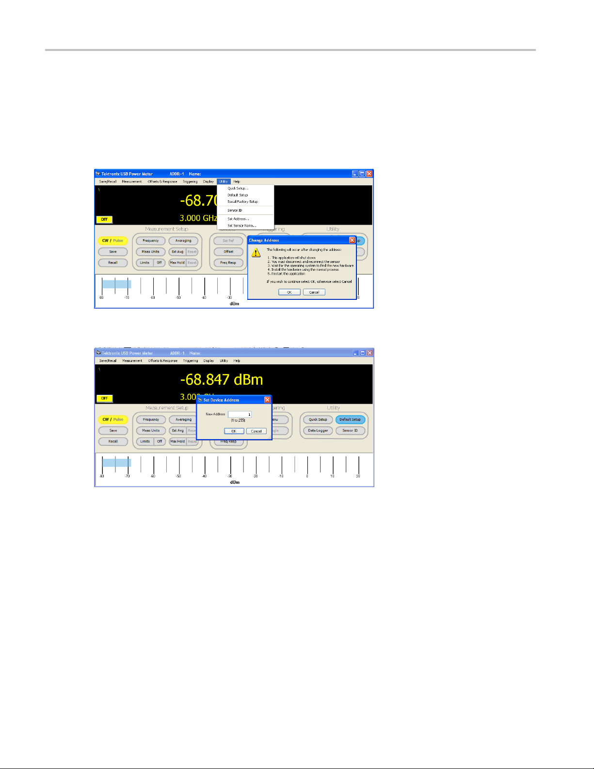
Set the Instrument Address
Next, you’ll need to set the instrument address:
1. Open the Power Meter application, which should be visible in the Tektronix menu (Start > Tektronix > Power Meter
2. After the Power Meter application opens, select the "Set Address" command found under the Utility menu tab. A window
3. After pressing "Ok", set the new address of the device and press "Ok", as shown below. Then allow the application to
Application > P ower Meter Application.
will open that lists the steps to follow in order to change the instrument address as shown below.
shut down.
4. Disconnect and reconnect the instrument.
5. Wait for the operating system to find the new hardware.
6. Restart the Power Meter application.
7. Confirm that the instrument address shown at the top of the Power Meter window is the correct address.
8. Close the Power Meter application.
4 PSM3000, PSM4000, and PSM5000 Series
Make a CW Measurement
When creating an application for making a simple continuous wave (CW) measurement, a similar approach is taken whether
you are using VB 6.0, VB .Net, or C#. The VB .NET and C# examples in this section were created using Microsoft Visual
Studio 2005. Thfor taking a measurementis code assumes that a single instrument has been connected to the computer and
has proven functional. If an earlier version of Visual Studio.NET is being used, the VB.NET and C# code may need minor
modification, as a direct copy and paste may not work.
NOTE. Before performing the following procedures, make sure you have installed the Sample Code application on
your PC and that the instrument and PC are communicating properly. For installation and functional check procedures,
see the Installation and Safety Instructions that shipped with your instrument. You can also download the manual from
www.tektronix.com.manuals.
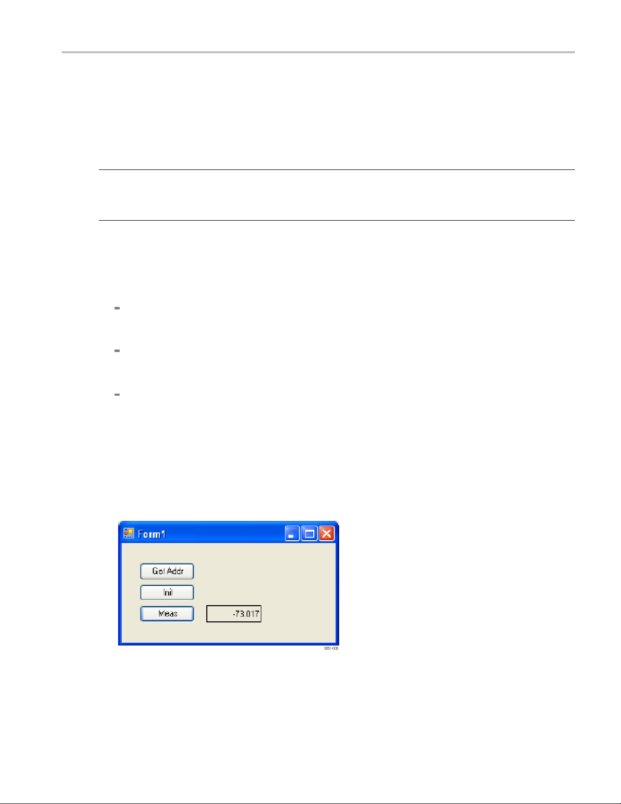
1. Start the code by creating a default Windows application.
2. Place three buttons and one label on the window or form.
3. Name the buttons as follows:
cmdGetAddress: Clicking this button uses the "LB_GetAddress_Idx" command. The name of this command can
be interpreted as "get the address using the index." In this case, the first instrument is used, or the instrument
with an index of 1.
Getting Started
cmdInitialize: Clicking this button uses the "LB_InitializeSensor_Addr" command. The name of this command can
be interpreted as "initialize the instrument using the address". Initialization causes the calibration constants and other
information for the instrument to be transferred to the PC.
cmdMeasure: Clicking this button uses the "LB_CWMeasure" command. The name of this command can be
interpreted as “make a measurement”. The result of the m easurement is converted to text and placed in the label.
This command requires the address acquired in the first button click. It also requires that the instrument be initialized,
as done in the second button click. In this API, most commands are designed for use with the address.
4. Name the label lblCW. The result of the measurement taken when the cmdMeasure command is used is converted to
text and placed in this label.
5. Copy the appropriate portions of code from the following pages.
6. Compile the application you have just coded. The window may look similar to the one shown here.
PSM3000, PSM4000, and PSM5000 Series 5
Getting Started
7. Run the application as follows:
a. Click the “Get Addr” or cmdGetAddress button.
b. Click the “Init” or cmdInitialize button. Wait for the message indicating initialization is complete. This typically
takes about 5 s
econds.
c. Click the “Mea
been initialized, this button can be clicked repeatedly for as many measurements as you would like.
s” or cmdMeasure button and a measurement should appear in the label. Now that the instrument has
Tips
A few items that may be of interest to some programmers are:
“Long” in VB 6.0 is equivalent to an “Integer” in VB.NET and “int” in C#.
The default ByRef/ByVal are switched when going from VB 6.0 to VB.NET and C#. We have taken the approach of
explicitly including the ByRef/ByVal declarations in all code. We highly recommend this practice.
Structures in VB 6.0 allowed the embedding of fixed arrays. This is/was commonly used for transferring complex
data types. The exact capability has not been duplicated in VB.NET and C#. VB.NET does have the following type
of declaration, which can be used inside a structure. However, it seems able to be passed via a_stdcall for simple
structures only.
<VBFixedArray(6)>Dim SerialNumber() As Byte
NOTE. If you are using an earlier version of Visual Studio.NET, the code may need some modification.
VB 6.0 Code
Option Explicit
e Declare Function LB_SensorCnt Lib _
Privat
"LB_API2.dll" () _
As Long
Private Declare Function LB_GetAddress_Idx _
Lib "LB_API2.dll" ( _
l addr As Long) _
ByVa
As Long
ate Declare Function LB_InitializeSensor_Addr _
Priv
Lib "LB_API2.dll" ( _
ByVal addr As Long) _
ong
As L
Private Declare Function LB_MeasureCW _
"LB_API2.dll" ( _
Lib
ByVal addr As Long, _
ByRef CW As Double) As Long
Dim m_Addr As Long
ivate Sub cmdG etAddress_Click()
Pr
6 PSM3000, PSM4000, and PSM5000 Series

If LB_SensorCnt() > 0 Then
m_Addr = LB_Get
End If
End Sub
Private Sub cmdInitialize_Click()
If LB_InitializeSensor_Addr(m_Addr) > 0 Then
MsgBox ("Ini
End If
End Sub
Private Sub cmdMeasure_Click()
Dim CW As Double, rslt As Long
rslt = LB_Me
If rslt > 0 Then lblCW.Caption = Format(CW, "###0.0###")
End Sub
asureCW(m_Addr, CW)
Address_Idx(1)
tialization OK")
Getting Started
VB.NET Cod
Public Class Form1
Public Declare Function LB_SensorCnt Lib _
Public Declare Function LB_GetAddress_Idx _
Public Declare Function LB_InitializeSensor_Addr _
Public Declare Function LB_MeasureCW _
Dim m_Addr As Integer
Private Sub cmdGetAddress_Click(ByVal sender As System.Object, _
End Sub
e (Visual Studio 2005)
"LB_API2.dll" () _
As Integer
Lib "LB_API2.dll" ( _
ByVal addr As Integer) _
As Integer
Lib "LB_API2.dll" ( _
ByVal addr As Integer) _
As Integer
Lib "LB_API2.dll" ( _
ByVal addr As Integer, _
ByRef CW As Double) As Integer
ByVal e As System.EventArgs) Handles cmdGetAddress.Click
If LB_SensorCnt() > 0 Then
m_Addr = LB_GetAddress_Idx(1)
End If
Private Sub cmdInitialize_Click(ByVal sender As System.Object, _
ByVal e As System.EventArgs) Handles cmdInitialize.Click
If LB_InitializeSensor_Addr(m_Addr) > 0 Then
PSM3000, PSM4000, and PSM5000 Series 7

Getting Started
MsgBox("Initialization OK")
End If
End Sub
Private Sub cm
Dim CW As Doub
rslt = LB_MeasureCW(m_Addr, CW)
If rslt > 0 The
End Sub
End Class
C# Code (Vi
using Microsoft.VisualBasic;
using System;
using System.Collections;
using System.Collections.Generic;
using System.Data;
using System.Drawing;
using System.Diagnostics;
using System.Windows.Forms;
namespace SimpleMeasurement
{
public partial class Form1
{
public Form1()
{
}
dMeasure_Click(ByVal sender As System.Object, _
ByVal e As System.EventArgs) Handles cmdMeasure.Click
le, rslt As Long
n lblCW.Text = Format(CW, "###0.0###")
sual Studio 2005)
InitializeComponent();
cmdGetAddress.Click += new System.EventHandler( cmdGetAddress_Click );
cmdInitialize.Click += new System.EventHandler( cmdInitialize_Click );
cmdMeasure.Click += new System.EventHandler( cmdMeasure_Click );
[System.Runtime.InteropServices.DllImport("LB_API2.dll")]
public static extern int LB_SensorCnt();
[System.Runtime.InteropServices.DllImport("LB_API2.dll")]
public static extern int LB_GetAddress_Idx( int addr );
[System.Runtime.InteropServices.DllImport("LB_API2.dll")]
public static extern int LB_InitializeSensor_Addr( int addr );
[System.Runtime.InteropServices.DllImport("LB_API2.dll")]
public static extern int LB_MeasureCW( int addr, ref double CW );
public int m _Addr;
private void cmdGetAddress_Click( System.Object sender, System.EventArgs e )
{
8 PSM3000, PSM4000, and PSM5000 Series

if ( LB_SensorCnt() > 0 )
{
m_Addr = LB_GetAddress_Idx( 1 );
}
}
private void cmdInitialize_Click( System.Object sender, System.EventArgs e )
{
if ( LB_InitializeSensor_Addr( m_Addr)>0)
{
Interaction
(Microsoft.VisualBasic.MsgBoxStyle)(0), null );
}
}
private void cmdMeasure_Click( System.Object sender, System.EventArgs e )
{
double CW = 0; long rslt = 0;
.MsgBox( "Initialization OK",
Getting Started
rslt = LB_M
if ( rslt > 0 )
{
}
}
}
}
easureCW( m_Addr, ref CW );
lblCW.Te
xt = Strings.Format( CW, "###0.0###" );
PSM3000, PSM4000, and PSM5000 Series 9

Command Groups
Command Group
The following command group tables organize commands together by functionality and link each command to the individual
command, located in the Commands Listed in Alphabetical Order section of this manual. (See page 22, Commands
Listed in Alphabetical Order.)
If a command has related commands, the related commands are indented to the primary command in the table. Primary
commands are listed in the Commands Listed in Alphabetical Order section, and in the table of contents.
NOTE. Unless otherwise noted the following commands are valid for all instrument models.
s
CW Measurement C om mand Group
Command
LB_MeasureCW
(See page 46, LB_MeasureCW.)
LB_MeasureCW_PF
(See page 48, LB_MeasureCW_PF .)
Description
Makes continuous wave (CW) measurements. The value returned is in
the units currently selected.
Makes continuous wave (CW) measurements and evaluates the
measurement relative to the current limit. The value returned is in the
units currently selected.
Initialization and Identification Com mand Group
Command
LB_AddressConflictExists
(See page 23, LB_AddressConflictExists.)
LB_BlinkLED_Addr
LB_BlinkLED_Idx
LB_BlinkLED_SN
(See page 24, LB_BlinkLED_Addr (and
related commands).)
LB_ChangeAddress
(See page 26, LB_ChangeAddress.)
LB_IsDeviceInUse_Addr
LB_IsDeviceInUse_Idx
LB_IsDeviceInUse_SN
(See page 40, LB_IsDeviceInUse_Addr
(and related commands).)
LB_DriverVersion
(See page 27, LB_DriverVersion.)
LB_GetFirmwareVersion
(See page 28, LB_GetFirmwareVersion.)
Description
Checks the address of all instruments that are connected to the system.
If any of the addresses match, a conflict is deemed to exist. If all the
addresses are unique to the system, a conflict is deemed not to exist.
Cause the instrument LED to blink four times.
Changes the address of the device. The address is changed from
“currentAddr” to “newAddr”.
Return a 1 if the device has been initialized and a 0 if the device has not
been initialized by the calling program or any other program.
Returns a 32 bit integer indicating the version of LB_API2.dll.
Returns a null-terminated string of chars indicating the firmware version.
10 PSM3000, PSM4000, and PSM5000 Series

Command Groups
Command
LB_GetIndex_
LB_GetIndex_SN
(See page 29, LB_GetIndex_Addr (and
related comma
LB_GetModel
LB_GetModelNumber_Idx
LB_GetModelNumber_SN
(See page 31, L
(and related commands).)
LB_GetSerNo_Addr
LB_GetSerNo_Idx
(See page 35,
related commands).)
LB_InitializeSensor_Addr
LB_InitializeSensor_Idx
LB_Init
(See page 37, LB_InitializeSensor_Addr
(and related commands) .)
LB_IsSensorConnected_Addr
LB_IsS
(See page 42, LB_IsSensorConnected_Addr (and related commands).)
LB_SensorCnt
(See p
etAddress_Idx
LB_S
LB_GetAddress_Idx
(See page 61, LB_SetAddress_Idx (and
ated commands).)
rel
SetAddress_SN
LB_
LB_GetAddress_SN
(See page 63, LB_S etAddress_SN (and
lated commands).)
re
_WillAddressConflict
LB
(See page 120, LB_WillAddressConflict.)
Addr
nds).)
Number_Addr
B_GetModelNumber_Addr
LB_GetSerNo_Addr (and
ializeSensor_SN
ensorConnected_SN
age 57, LB_SensorCnt.)
Description
Return the index given to the serial number or address.
Return a value equating to a model number enumeration.
Return the
Cause the instrument to be initialized.
Determine if the specified instrument is connected. The query is based
on the s
Returns the number of instruments currently connected to the computer.
Return the address, given the index and vice versa. The index is
assi
Return the address, given the serial number and vice versa.
ecks the address of all instruments connected to the system. If any of
Ch
the addresses match, a conflict is deemed to exist.
serial number given the index or address.
erial number or address.
gned by the OS when the unit is plugged in.
PSM3000, PSM4000, and PSM5000 Series 11

Command Groups
Pulse Measurement Command Group
NOTE. These co
Command
LB_MeasureBurst_DBM
(See page 44, LB_MeasureBurst_DBM.)
LB_MeasurePulse
(See page 51, L
LB_Measur
(See page 53, LB_MeasurePulse_PF.)
mmands are only valid for PSM4000 and PSM5000 Series instruments.
B_MeasurePulse.)
ePulse_PF
Pulse Setup Command Group
NOTE. These commands are only valid for PSM4000 and PSM5000 Series instruments.
Command
LB_SetAutoPulseEnabled
LB_GetAutoPulseEnabled
age 67, LB_SetAutoPulseEnabled
(See p
(and related commands) .)
LB_SetPulseCriteria
LB_GetPulseCriteria
page 100, LB_SetPulseCriteria (and
(See
related commands) .)
LB_SetPulseReference
LB_GetPulseReference
e page 103, LB_SetPulseReference
(Se
(and related commands) .)
Description
Measures the peak power, minimum power and average power over a
specified measurement interval or burst. The measurement is made
relative to
Makes pulse measurements. The measurement returns pulse power
(average po
averge power; and duty cycle.
Makes puls
the pulse power (instead of peak or average) is evaluated against the
selected limit.
Descrip
Enable or disable the default or automatic pulse measurement criteria.
Set or get the pulse measurement criteria.
Configure the instrument for relative measurements during pulse
measurements. (Other commands set a reference for CW
mea
a trigger.
wer in the pulse); peak power (highest sample measured);
e measurements just as LBMeasurePulse does, except that
tion
surements.)
lse Profiling Gate Command Group
Pu
NOTE. These commands are valid only for the PSM5000 Series instrument.
12 PSM3000, PSM4000, and PSM5000 Series

Command Groups
Command
PP_GatePosit
ionIsValid
(See page 126, PP_GatePositionIsValid .)
PP_GetGateCrestFactor
(See page 128, PP_GetGateCrestFactor.)
PP_GetGateDroop
(See page 129, P
P_GetGateDroop.)
PP_GetGateDutyCycle
(See page 130, PP_GetGateDutyCycle .)
PP_GetGateEndPosition
(See page
PP_GetGa
132, PP_GetGateEndPosition .)
teFallTime
(See page 133, PP_GetGateFallTime .)
PP_GetGateOverShoot
(See page 135, PP_GetGateOverShoot .)
PP_GetGatePeakPower
ge 136, PP_GetGatePeakPower .)
(See pa
tGatePRF
PP_Ge
(See page 137, PP_GetGatePRF.)
PP_GetGatePRT
page 139, PP_GetGatePRT.)
(See
PP_GetGatePulsePower
(See page 141, PP_GetGatePulsePower .)
PP_GetGatePulseWidth
ee page 143, PP_GetGatePulseWidth .)
(S
_GetGateRiseTime
PP
(See page 145, PP_GetGateRiseTime .)
PP_SetGateStartEndPosition
PP_SetGateStartEndTime
PP_GetGateStartEndTime
PP_SetGateStartPosition
PP_GetGateStartPosition
PP_SetGateEndPosition
PP_GetGateEndPosition
PP_SetGateStartTime
PP_GetGateStartTime
PP_SetGateEndTime
PP_GetGateEndTime
(See page 179, PP_SetGateStartEndPosition (and related commands).)
Description
Determines wh
ether the specified gate is valid. The gate index may
be 0..4.
Returns the create factor (in dB) of the span in the analysis trace
specified by the gate.
Returns the droop of the span in the analysis trace specified by the gate.
The droop wi
ll be the difference in power between the area at beginning
and end of the gate edges.
Returns the duty cycle (as a decimal) of span in the analysis trace
specified by the gate.
Returns the location, as an index in the analysis trace, of the right side
of the spe
Returns t
cified gate.
he fall time in microseconds of the pulse delineated by the
selected gate.
Returns
the overshoot in dB.
Returns the peak power measured of the analysis trace as defined by
e edges.
the gat
ns the pulse repetition frequency (PRF) in Hertz, as defined by the
Retur
inverse of the time between the rising edges of the first two complete
pulses present in the span defined by the gate (gateIdx).
Returns the pulse repetition time (PRT) in microseconds using the same
rithm defined for PRF. The sole difference is that time instead of
algo
frequency is returned.
urns average pulse power.
Ret
Measures the pulse width in microseconds.
Returns rise time in microseconds.
Sets or gets the gate start (left side) and/or end (right side) in terms of
trace index or time.
PSM3000, PSM4000, and PSM5000 Series 13

Command Groups
Pulse Profiling Marker Command Group
NOTE. These co
Command
PP_GetMarkerAmp
(See page 146, P
PP_GetMark
(See page 147, PP_GetMarkerDeltaAmp .)
PP_Marker
(See page 162, PP_MarkerPosIsValid.)
PP_Marke
PP_MarkerToLowestPk
PP_MarkerToFirstPk
PP_Marke
PP_MarkerPrevPk
PP_MarkerNextPk
PP_Mark
PP_MarkerPkLower
(See page 163, PP_MarkerToPk (and
relate
tMarkerDeltaTime
PP_Se
PP_GetMarkerDeltaTime
(See page 184, PP_SetMarkerDeltaTime
(and r
etMarkerMode
PP_S
PP_GetMarkerMode
(See page 186, PP_SetMarkerMode (and
ted commands) .)
rela
SetMarkerPosition
PP_
PP_GetMarkerPosition
PP_SetMarkerPositionTime
_GetMarkerPositionTime
PP
(See page 188, PP_SetMarkerPosition
(and related commands).)
mmands are valid only for the PSM5000 Series instrument.
P_GetMarkerAmp .)
erDeltaAmp
PosIsValid
rToPk
rToLastPk
erPkHigher
d commands) .)
elated commands) .)
Description
Returns the amplitude of the trace at the point indicated by the marker.
Returns the
delta marker in dBm.
Returns the state of the selected marker.
Set one of five markers (0<=mrkIdx<=4) to the position specified in the
command.
Sets o
Sets
s or gets the position of the normal or delta marker depending on
Set
the marker mode.
difference in amplitude between the normal marker and the
r gets the positions the selected marker in microseconds.
or gets the marker mode to on, normal or delta marker.
14 PSM3000, PSM4000, and PSM5000 Series

Pulse ProfilingSetupCommandGroup
Command Groups
NOTE. These co
Command
PP_GetPulseEdgesTime
PP_GetPuls
(See page 152, PP_GetPulseEdgesTime
(and related commands).)
PP_SetAvgMode
PP_GetAvg
PP_GetTraceAvgs
PP_ResetTraceAveraging
(See page
related commands).)
PP_SetAvgResetSens
PP_GetAvgResetSens
(See pag
related commands).)
PP_SetClosestSweepTimeUSEC
(See page 173, PP_SetClosestSweepTimeUSE
tFilter
PP_Se
PP_GetFilter
(See page 174, PP_SetFilter (and related
comm
etGateMode
PP_S
PP_GetGateMode
(See page 177, P P_SetGateMode (and
ated commands) .)
rel
SetMeasurementThreshold
PP_
PP_GetMeasurementThreshold
(See page 190, PP_SetMeasurement-
reshold (and related commands).)
Th
P_SetPoles
P
PP_GetPoles
(See page 192, PP_S etPoles (and related
ommands) .)
c
PP_SetSweepDelay
PP_GetSweepDelay
(See page 194, PP_SetSweepDelay (and
related commands).)
mmands are valid only for the PSM5000 Series instrument.
eEdgesPosition
Mode
169, PP_SetAvgMode (and
e 172, PP_SetAvgResetSens (and
C.)
ands) .)
Description
Return the index of the leading and trailing edges of the pulse
containing
Set, auto-set or manual reset the averaging mode.
Set or get the criteria used to reset the averaging when the
averaging mode is AVG_AUTO_RESET (see PP_SetAvgMode and
PP_GetA
Sets the sweep time to the fixed sweep time closest to the sweep time
sent (in microseconds) to the command.
Sets o
Sets
Set
along with the peak criteria, affects a number of measurement
commands, especially the peak commands.
ets or gets the number of poles in the current filter.
S
Sets or gets the sweep delay in microseconds. Sweep delay is the
time between the trigger and the start of data acquisition.
the peak defined by pkTime or pkIdx.
vgMode).
r gets the enumeration associated with the current filter settings.
or gets the gate mode.
s or gets the measurement threshold. The measurement threshold,
PSM3000, PSM4000, and PSM5000 Series 15

Command Groups
Command
PP_SetSweepD
PP_GetSweetDelayMode
(See page 196, PP_SetSweepDelayMode
(and related c
PP_SetSweep
PP_GetSweepHoldOff
(See page 197, PP_SetSweepHoldOff (and
related com
PP_SetSwe
PP_GetSweepTime
(See page 198, PP_SetSweepTime (and
related co
PP_SetTi
PP_GetTimeOut
(See page 200, PP_SetTimeOut (and related
command
elayMode
ommands).)
HoldOff
mands).)
epTime
mmands).)
meOut
s).)
Description
Turns the swee
unchanged.
Specifies the
trace is taken.
Sets or get
taken. Sweep time is a 1, 2, 5 sequence starting with 10 μsec and
ending with 1 second.
Sets or ge
Pulse Profiling Status Command Group
p delay on or off. The sweep delay parameter remains
length of time (in microseconds) to wait after a sweep or
s the sweep time (in microseconds) for the next sweep
ts the timeout used while taking a trace.
NOTE. T
Command
PP_AnalysisTraceIsValid
PP_CheckTrigger
hese commands are valid only for the PSM5000 Series instrument.
Description
Checks to ensure that the current analysis trace is valid. If the analysis
(See page 121, PP_AnalysisTraceIsValid .)
page 122, PP_CheckTrigger .)
(See
trace
Checks the trigger source for an active trigger. If a trigger is detected, a
valu
Pulse Profiling Trace Command Group
E. These commands are valid only for the PSM5000 Series instrument.
NOT
mmand
Co
PP_CnvtTrace
See page 123, PP_CnvtTrace.)
(
PP_CurrTrace2AnalysisTrace
See page 125, PP_CurrTrace2AnalysisTrace
(
.)
Description
Converts a trace (trIn) from one unit to another, and stores the converted
v
Copies the current trace to the analysis trace and returns a copy of that
race.
t
is valid, a 1 is returned; if it is not valid, a 0 or less is returned.
e > 0 is returned; if a trigger is not detected, a value <= 0 is returned.
alues in a new trace (trOut).
16 PSM3000, PSM4000, and PSM5000 Series

Command Groups
Command
PP_GetAnalys
(See page 127, PP_GetAnalysisTraceLength
.)
PP_GetPeaks_Val
PP_GetPeaks_Idx
PP_GetPeak
PP_GetPeaksFromTr_Idx
PP_GetPeaks_VEE_Idx
PP_GetPeak
(See page 148, PP_GetPeaks_Val (and
related commands) .)
PP_GetPulseEdgesTime
PP_GetPulseEdgesPosition
(See page
(and related commands).)
PP_GetT
(See page 155, PP_GetTrace.)
PP_Get
PP_GetTraceCrestFactor
PP_GetTraceDC
PP_Ge
PP_GetTracePulsePower
(See page 158, PP_GetTraceAvgPower (and
relat
isTraceLength
sFromTr_Val
s_VEE_Val
152, PP_GetPulseEdgesTime
race
TraceAvgPower
tTracePkPwr
ed commands) .)
Description
Returns a 32 bi
Return a set of peaks from either the analysis trace (PP_GetPeaks_Val
and PP_GetPeaks_Idx) or from a trace passed to the command.
Returns the index of the leading and trailing edges of the pulse containing
the peak defined by pkTime or pkIdx.
Causes t
trace is an array of equally spaced (in time) samples, in dBm.
Make a n
commands, but operate on a single trace instead of a set of random
samples.
t integer indicating the length of the analysis trace.
he instrument to take a trace and return the resultant data. The
umber of measurements similar to the power meter measurement
PP_GetTraceLength
page 160, PP_GetTraceLength.)
(See
PP_SetAnalysisTrace
GetAnalysisTrace
PP_
(See page 167, P P_SetAnalysisTrace (and
related commands).)
Returns the number of trace points associated with the current sweep time.
Enable the user to get and set the analysis trace directly. These are
companions to PP_CurrTrace2AnalysisTrace.
PSM3000, PSM4000, and PSM5000 Series 17

Command Groups
Pulse ProfilingTriggerCommandGroup
NOTE. These co
Command
PP_SetTriggerEdge
PP_GetTrig
(See page 201, PP_SetTriggerEdge (and
related commands).)
PP_SetTriggerLevel
PP_GetTri
(See page 203, PP_SetTriggerLevel (and
related commands) .)
PP_SetTriggerOut
PP_GetTr
(See page 205, PP_SetTriggerOut (and
related commands).)
PP_SetTriggerSource
PP_Get
(See page 207, PP_SetTriggerSource (and
related commands).)
mmands are valid only for the PSM5000 Series instrument.
gerEdge
ggerLevel
iggerOut
TriggerSource
Description
Sets or gets the trigger signal edge on which the beginning of the trace
will occur.
Sets or gets the trigger level for internal triggering (manual or automatic),
in dBm.
Sets or gets the trigger out mode. The trigger out can be off (no trigger
out)orit
relative to the input trigger).
Sets or gets the trigger source. Trigger source can be internal or external.
The values are positive edge or negative edge.
can be normal (same polarity as the input trigger or inverted
Save/Recall Command Group
Command
LB_ReadStateFromINI
LB_WriteStateToINI
page 56, LB_ReadStateFromINI (and
(See
related commands).)
LB_ResetRegStates
LB_ResetCurrentState
ee page 55, LB_ResetRegStates (and
(S
related commands).)
LB_StoreReg
LB_RecallReg
See page 118, LB_StoreReg (and related
(
commands).)
iption
Descr
Cause the current state, including all numbered registers to be written
to an INI file.
Enable the user to cause either the current state or the state information
held in the save/recall registers to be reset.
Store/recall register commands. There are 20 registers and each
register holds an entire state.
18 PSM3000, PSM4000, and PSM5000 Series

Service Command Group
Command Groups
Command
LB_SetCalDueDate
(See page 71, LB
related commands) .)
Setup Comma
Command
LB_Set75O
LB_SetAn
LB_Set
LB_Se
LB_S
LB_SetExtendedAveraging
hmsEnabled
LB_Get75OhmsEnabled
(See page 60, LB_Set75OhmsEnabled
(and rela
tiAliasingEnabled
LB_GetAntiAliasingEnabled
(See page 65, LB_SetAntiAliasingEnabled
ated commands).)
(and rel
Averages
LB_GetAverages
(See page 69, LB_SetAverages (and
d commands).)
relate
tCWReference
LB_GetCWReference
(See page 74, LB_SetCWReference (and
ted commands).)
rela
etDutyCycleEnabled
LB_GetDutyCycleEnabled
LB_SetDutyCyclePerCent
GetDutyCyclePerCent
LB_
(See page 76, LB_SetDutyCycleE nabled
(and related commands).)
_GetExtendedAveraging
LB
LB_SetExtendedAveragingEnabled
LB_GetExtendedAveragingEnabled
B_GetExtendedAveragingEnabled
L
LB_ResetExtendedAveraging
(See page 79, LB_SetExtendedAveraging
and related commands).)
(
_SetCalDueDate (and
nd Group
ted commands).)
Description
Set or get the calibration due date, which is specified by serial number,
not address.
Description
Used to correct measurements made using a minimum loss pad.
Enable or
checked.
Set or g
is set to 75.
Set up
measurements.
Set u
on an assumed duty cycle value.
Manage the extended average settings of the instrument. Extended
eraging uses a form of exponential averaging.
av
disable the anti-aliasing feature or allow its state to be
et the number of data buffers that are averaged. The default
the instrument for relative measurements during CW
p the instrument for average pulse power measurements based
PSM3000, PSM4000, and PSM5000 Series 19

Command Groups
Command
LB_SetFreque
LB_GetFrequency
(See page 82, LB_S etFrequency (and
related comma
LB_SetLimit
LB_GetLimitEnabled
LB_SetSingleSidedLimit
LB_GetSing
LB_SetDoubleSidedLimit
LB_GetDoubleSidedLimit
(See page 84,
related commands).)
LB_SetMaxHoldEnabled
LB_GetMaxHoldEnabled
LB_Reset
(See page 93, LB_SetMaxHoldEnabled
(and related commands) .)
LB_SetMeasurementPowerUnits
LB_GetM
(See page 95, LB_SetMeasurementPowerUnits (and related commands) .)
LB_SetOffset
LB_Ge
LB_SetEnabled
LB_GetEnabled
(See p
commands).)
LB_SetResponseEnabled
LB_GetResponseEnabled
LB_
LB_GetResponse
(See page 106, LB_SetResponseEnabled
(an
ncy
nds).)
Enabled
leSidedLimit
LB_SetLimitEnabled (and
MaxHold
easurementPowerUnits
tOffset
age 97, LB_SetOffset (and related
SetResponse
d related commands).)
Description
Set or get the f
Set and get li
or neither limit.
Cause CW or pulse measurements to retain the greater of the most
recent measurement or previous measurements.
Set or get the measurement power units.
Cause a fixed offset to be added to the reading, or enable/disable the
re.
featu
Set the response, which is a frequency sensitive offset, and
enable/disable the feature.
requency of the addressed device, in Hz.
mits, and specify single-sided limits, double- sided limits,
20 PSM3000, PSM4000, and PSM5000 Series

Trigger Com mand Group
Command Groups
Command
LB_SetTTLTriggerInEnabled
LB_GetTTLTr
LB_SetTTLTriggerInInverted
LB_GetTTLTriggerInInverted
LB_SetTTLT
LB_GetTTLTriggerInTimeOut
(See page 110, LB_SetTTLTriggerInEnabled
(and relate
LB_SetTTL
LB_GetTTLTriggerOutEnabled
LB_SetTTLTriggerO utInverted
LB_GetTT
(See page 114, LB_SetTTLTriggerOutEnabled (and related commands).)
iggerInEnabled
riggerInTimeOut
d commands).)
TriggerOutEnabled
LTriggerOutInverted
Description
Control or read back the state of the external trigger input. The
trigger-in c
can be set or read.
Control th
inverted or normal.
an be enabled, disabled or inverted; or the timeout value
e trigger output of the device. It can be enabled, disabled,
PSM3000, PSM4000, and PSM5000 Series 21

Commands Listed
in Alphabetical Order
Commands List
The following commands are exported from a Visual C++ 2005 project. The calling convention used is _stdcall. The
declarations are shown in various examples for C++, C#, VB 6.0, and/or VB.NET.
Thedriverisinstalledusinga.inffile. The supplied apausb.inf file is in the Tektronix\Tektronix Power Sensor Applications
directory of the install directory.
The declarations for the various programming environments are in the application directory and in various subdirectories.
These files include the type or structure declarations and some useful constants. The files are named as follows:
C#
VB.NET LB2_Declarations.vb
NOTE. Pre-allocated buffers are often required when strings (such as serial number) or arrays are being passed back from
the driver by reference (or pointer).
ed in Alphabetical Order
LB_API2_Declarations.cs
22 PSM3000, PSM4000, and PSM5000 Series

LB_AddressConflictExists
This command checks the address of all instruments that are connected to the system. If any of the addresses match, a
conflict is deemed to exist. If all the addresses are unique to the system, a conflict is deemed not to exist.
Pass Parameters:
None
Returned Values:
Conflict Exists = 1
Conflict does not exit = 0
Error < 0
Command Group:
Initialization and Identification
(See page 10, Initialization and Identification Command Group.)
Commands Listed
in Alphabetical O rder
Sample Code Declarations:
C++ LB_API2 long _stdcall LB_A ddressCon flictExists();
VB 6.0
VB.NET
C# [Sy
c Declare Function LB_AddressConflictExists _
Publi
Lib "LB_API2.dll" ()
_ As Long
ic Declare Function LB_AddressCon flictExists _
Publ
Lib "LB_API2.dll" () _
As Integer
stem.Runtime.InteropServices.DllImport("LB_API2.dll")]
public static extern int LB_AddressConflictExists();
PSM3000, PSM4000, and PSM5000 Series 23

Commands Listed
in Alphabetical Order
LB_BlinkLED_Addr (and related commands)
Related Commands:
LB_BlinkLED_
Idx
LB_BlinkLED_SN
These comma
physically.
nds cause the instrument LED to blink four times. This is intended to allow the user to ID the instrument
Pass Parameters:
Index, serial number or address
Returned Values:
Success: > 0
Error: <= 0
Comman
d Group:
Initialization and Identification
(See page 10, Initialization and Identification Command Group.)
Sample Code Declarations:
C++ LB_API2 long _stdcall LB_BlinkLED_SN(char* SN);
LB_API2 long _stdcall LB _BlinkLED_Idx(long idx);
LB_API2 long _stdcall LB_BlinkLED_Addr(long addr);
VB 6.0
Public Declare Function LB_BlinkLED_SN _
Lib "LB_API2.dll" ( _
ByVal sn As String) _
As Long
Public Declare Function LB_BlinkLED_Idx _
Lib "LB_API2.dll" ( _
ByVal idx As Long) _
As Long
Public Declare Function LB_BlinkLED_Addr _
Lib "LB_API2.dll" ( _
ByVal addr As Long) _
As Long
24 PSM3000, PSM4000, and PSM5000 Series

VB.NET
Public Declar
Lib "LB_API2.dll" ( _
ByVal sn As String) _
Public Declare Function LB_BlinkLED_Idx _
Lib "LB_API2
ByVal idx As Integer) _
Public Declare Function LB_BlinkLED_Addr _
Lib "LB_API2.dll" ( _
ByVal addr A
C# [System.Runtime.InteropServices.DllImport("LB_API2.dll")]
public st
e Function LB_BlinkLED_SN _
As Integer
.dll" ( _
As Integer
s Integer) _
As Integer
atic extern int LB_BlinkLED_SN(
string sn );
Commands Listed
in Alphabetical O rder
[System.
public static extern int LB_BlinkLED_Idx(
[System.Runtime.InteropServices.DllImport("LB_API2.dll")]
Runtime.InteropServices.DllImport("LB_API2.dll")]
int idx );
public static extern int LB_BlinkLED_Addr(
r);
int add
PSM3000, PSM4000, and PSM5000 Series 25

Commands Listed
in Alphabetical Order
LB_ChangeAddress
This command changes the address of the device. The address is changed from “currentAddr” to “newAddr”. The address is
retained in non-volatile memory.
Pass Parameters:
currentAdd
newAddr = 1 t
r=1to255
o 255
Returned Values:
Success: > 0
Failure: < 0
Command Group:
Initialization and Identification
(See page 10, Initialization and Identification Command Group.)
Sample Code Declarations:
C++ LB_API2 long _stdcall LB_ChangeAddress(long currentAddr, long newAddr);
VB 6.0
c Declare Function LB_ChangeAddress _
Publi
Lib "LB_API2.dll" ( _
ByVal currentAddr As Long, _
l newAddr As Long) _
ByVa
As Long
VB.NET
C# [System.Runtime.InteropServices.DllImport("LB_API2.dll")]
26 PSM3000, PSM4000, and PSM5000 Series
Public Declare Function LB_ChangeAddress _
"LB_API2.dll" ( _
Lib
ByVal currentAddr As Integer, _
ByVal newAddr As Integer) _
nteger
As I
public static extern int LB_ChangeAddress(
nt currentAddr,
i
int newAddr );

LB_DriverVersion
This command returns a 32 bit integer indicating the version of LB_API2.dll.
Pass Parameters:
None
Returned Values:
The least two significant digits indicate the revision number. The next two least significant digits represent the minor version.
The most significant digit(s) represent the major version. As of this writing, the value returned is 45030, so that:
30 is the revision,
50 is the minor version,
4 is the major version.
Command Group:
ization and Identification
Initial
Commands Listed
in Alphabetical O rder
(See pag
e 10, Initialization and Identification Command Group.)
Sample Code Declarations:
C++ Long LB_DriverVersion(void)
VB.NET
C# [Sys
Public Declare Function LB_DriverVersion Lib “LB_API2.dll” () as Integer
tem.Runtime.InteropServices.DllImport("LB_API2.dll")]
public static extern int LB_DriverVersion();
PSM3000, PSM4000, and PSM5000 Series 27

Commands Listed
in Alphabetical Order
LB_GetFirmwareVersion
This command returns a null-terminated string of chars indicating the firmware version.
Pass Parameters:
addr is a 32 bit integer containing the address of the device.
buff is a pointer to an array or buffer of chars. The characters must be allocated by the calling command.
The buffer m
ust be at least 14 chars long and should contain the value zero.
buffLen ind
icates the length of buff. The l ength of buff must be at least 14 chars.
Returned Values:
A return value of greater than zero indicates success. A return value of less than zero indicates failure. The version
information is returned in buff. The current value of buff is “1.28 07/08/08”. The first part (1.28) indicates the major and minor
version. The second part indicates the date.
Command Group:
ization and Identification
Initial
ge 10, Initialization and Identification Command Group.)
(See pa
Sample Code Declarations:
C++ Long LB_GetFirmwareVersion(long addr, char* buff, long buffLen);
VB.NET
C# [System.Runtime.InteropServices.DllImport("LB_API2.dll")]
Public Declare Function LB_GetFirmwareVersion Lib "LB_API2.dll" (ByVal addr As Integer, ByRef buff As
, ByVal buffLen As Integer) As Integer
Byte
public static extern int LB_GetFirmwareVersion(int addr, ref byte buff, int buffLen);
28 PSM3000, PSM4000, and PSM5000 Series

LB_GetIndex_Addr (and related commands)
Related Commands:
Commands Listed
in Alphabetical O rder
LB_GetIndex_
These commands return the index given to the serial number or address.
SN
Pass Parameters:
Serial numb
er or address
Returned Values:
Success: > Index greater than 0
Error: <= 0
Command Group:
Initialization and Identification
(See page 10, Initialization and Identification Command Group.)
Sample Code Declarations:
C++ LB_API2 long _stdcall LB_G etIndex_SN(char* SN);
VB 6.0
LB_API2 long _stdcall LB_GetIndex_A ddr(long addr);
Public Declare Function LB_GetIndex_SN _
LB_API2.dll" ( _
Lib "
ByVal sn As String) _
As Long
Public Declare Function LB_GetIndex_Addr _
Lib "LB_API2.dll" ( _
al addr As Long) _
ByV
As Long
PSM3000, PSM4000, and PSM5000 Series 29

Commands Listed
in Alphabetical Order
VB.NET
C# [System.Runtime.InteropServices.DllImport("LB_API2.dll")]
Public Declar
Lib "LB_API2.dll" ( _
ByVal sn As String) _
As Integer
Public Declare Function LB_GetIndex_Addr Lib "LB_API2.dll" ( _
ByVal addr As
As Integer
public stat
string sn );
[System.R
public static extern int LB_GetIndex_Addr(
int addr );
e Function LB_GetIndex_SN _
Integer) _
ic extern int LB_GetIndex_SN(
untime.InteropServices.DllImport("LB_API2.dll")]
30 PSM3000, PSM4000, and PSM5000 Series

LB_GetModelNumber_Addr (and related commands)
Related Commands:
Commands Listed
in Alphabetical O rder
LB_GetModelN
umber_Idx
LB_GetModelNumber_SN
These comma
must be passed. The suffix ( _SN, _Idx or Addr) denotes the type of pass parameter.
nds return a value equating to a model number enumeration. In each case, the serial number, index or address
Pass Parameters:
Serial number, address or index.
Returned Values:
Returned values are -1 to 113 as denoted by the enumerations below.
Command
Initialization and Identification
(See page 10, Initialization and Identification Command Group.)
Group:
PSM3000, PSM4000, and PSM5000 Series 31

Commands Listed
Sample Code Declarations:
C++ enum MODEL_NUMBER {
in Alphabetical Order
Unknown = -1,
PSM4110 = 101,
PSM4120 = 102,
PSM5110 = 103,
PSM5120 = 104,
PSM3110 = 105,
PSM3120 = 106
PSM3310 = 107,
PSM3320 = 108,
PSM3510 = 10
PSM4410 = 110,
PSM4320 = 111,
PSM5410 = 1
PSM5320 = 113
};
LB_API2 long _stdcall LB_GetModelNumber_SN(char* SN,
LB_API2 long _stdcall LB_GetModelNumber_Idx(long idx,
,
9,
12,
MODEL_NUMBER* modelNumber);
MODEL_NUMBER* modelNumber);
LB_API2 long _stdcall LB_GetModelNumber_Addr(long addr,
MODEL_NUMBER* modelNumber);
32 PSM3000, PSM4000, and PSM5000 Series

Commands Listed
in Alphabetical O rder
VB 6.0
Public Enum MO
Unknown = -1
PSM4110 = 101
PSM4120 = 102
PSM5110 = 103
PSM5120 = 104
PSM3110 = 105
PSM3120 = 106
PSM3310 = 107
PSM3320 = 10
PSM3510 = 109
PSM4410 = 110
PSM4320 = 11
PSM5410 = 112
PSM5320 = 113
End Enum
Public Declare Function LB_GetModelNumber_SN _
Lib "LB_AP
ByVal sn As String, _
ByRef modelNumber As MO DE L_NUMBER) _
As Long
Public Declare Function LB_GetModelNumber_Idx _
Lib "LB_
ByVal idx As Long, _
ByRef modelNumber As MO DE L_NUMBER) _
As Long
DEL_NUMBER ' Enumeration of model numbers
8
1
I2.dll" ( _
API2.dll" ( _
VB.NE
Public Declare Function LB_GetModelNumber_Addr _
_API2.dll" ( _
Lib "LB
ByVal addr As Long, _
ByRef modelNumber As MO DE L_NUMBER) _
g
As Lon
T
Public Enum MODEL_NUMBER
Unknown = -1
110 = 101
PSM4
PSM4120 = 102
PSM5110 = 103
120 = 104
PSM5
PSM3110 = 105
PSM3120 = 106
3310 = 107
PSM
PSM3320 = 108
PSM3510 = 109
4410 = 110
PSM
PSM4320 = 111
PSM5410 = 112
M5320 = 113
PS
End Enum
PSM3000, PSM4000, and PSM5000 Series 33

Commands Listed
in Alphabetical Order
Public Declar
ByRef modelNu
Public Decla
ByRef model
Public Decl
ByRef mode
C# public enum MODEL_NUMBER
{ // Enume
}
e Function LB_GetModelNumber_SN _
Lib "LB_API2.dll" ( _
ByVal sn As String, _
mber As MODEL_NUMBER) _
As Integer
re Function LB_GetModelNumber_Idx _
Lib "LB_API2.dll" ( _
ByVal idx As Integer, _
Number As MODEL_NUMBER) _
As Integer
are Function LB_GetModelNumber_Addr _
Lib "LB_API2.dll" ( _
ByVal addr As Integer, _
lNumber As MODEL_NUMBER) _
As Integer
ration of model numbers
Unknown = -1,
PSM4110 = 101,
PSM4120
PSM5110 = 103,
PSM5120 = 104,
PSM3110
PSM3120 = 106,
PSM3310 = 107,
PSM332
PSM3510 = 109,
PSM4410 = 110,
PSM432
PSM5410 = 112,
PSM5320 = 113
= 102,
= 105,
0 = 108,
0=111,
[System.Runtime.InteropServices.DllImport("LB_API2.dll")]
ic static extern int LB_GetModelNumber_SN(
publ
string sn,
ref MODEL_NUMBER modelNumber);
[System.Runtime.InteropServices.DllImport("LB_API2.dll")]
public static extern int LB_GetModelNumber_Idx(
idx,
int
ref MODEL_NUMBER modelNumber);
stem.Runtime.InteropServices.DllImport("LB_API2.dll")]
[Sy
public static extern int LB_GetModelNumber_Addr(
int addr,
f MODEL_NUMBER modelNumber);
re
34 PSM3000, PSM4000, and PSM5000 Series

LB_GetSerNo_Addr (and related commands)
Related Commands:
Commands Listed
in Alphabetical O rder
LB_GetSerNo_
These commands return the serial number given the index or address. These and other similar commands require a
pre-allocated buffer.
Idx
Pass Parameters:
Index or address
Returned Values:
Success: > 0
Error: <= 0
Command Group:
Initialization and Identification
(See page 10, Initialization and Identification Command Group.)
e Code Declarations:
Sampl
C++ LB_AP
LB_API2 long _stdcall LB_GetSerNo_Addr(long addr, char* SN);
VB 6.0
Public Declare Function LB_GetSerNo_Idx _
Public Declare Function LB_GetSerNo_Addr _
I2 long _stdcall LB_GetSerNo_Idx(long idx, char* SN);
LB_API2.dll" ( _
Lib "
ByVal idx As Long, _
ByVal sn As String) _
ong
As L
"LB_API2.dll" ( _
Lib
ByVal address As Long, _
ByVal sn As String) _
Long
As
PSM3000, PSM4000, and PSM5000 Series 35

Commands Listed
in Alphabetical Order
VB.NET
C# [System.Runtime.InteropServices.DllImport("LB_API2.dll")]
Public Declar
Public Decla
public sta
[System.Runtime.InteropServices.DllImport("LB_API2.dll")]
public st
e Function LB_GetSerNo_Idx _
Lib "LB_API2.dll" ( _
ByVal idx As Integer, _
ByVal sn As Str
As Integer
re Function LB_GetSerNo_Addr _
Lib "LB_API2.dll" ( _
ByVal address As Integer, _
ByVal sn As S
As Integer
tic extern int LB_GetSerNo_Idx( int idx, string sn );
atic extern int LB_GetSerNo_Addr( int address, string sn );
ing) _
tring) _
36 PSM3000, PSM4000, and PSM5000 Series

LB_InitializeSensor_Addr (and related commands)
Related Commands:
Commands Listed
in Alphabetical O rder
LB_Initializ
eSensor_Idx
LB_InitializeSensor_SN
These comma
required to operate the instrument. Initialization normally takes about five seconds.
nds cause the instrument to be initialized. This includes downloading the calibration factors and other data
Pass Parameters:
Index, serial number or address
Returned Values:
Success: > 0
Error: <= 0
Comman
d Group:
Initialization and Identification
(See page 10, Initialization and Identification Command Group.)
PSM3000, PSM4000, and PSM5000 Series 37

Commands Listed
Sample Code Declarations:
C++ LB_API2 long _stdcall LB_InitializeSensor_SN(char* SN);
in Alphabetical Order
LB_API2 long _stdcall LB_InitializeSensor_Idx(long idx);
VB 6.0
LB_API2 long
Public Declare Function LB_InitializeSensor_SN _
Lib "LB_API2.dll" ( _
ByVal sn As S
As Long
Public Dec
Lib "LB_API2.dll" ( _
ByVal idx As Long) _
As Long
Public Declare Function LB_InitializeSensor_Addr _
Lib "LB_A
ByVal addr As Long) _
As Long
_stdcall LB_InitializeSensor_Addr(long addr);
tring) _
lare Function LB_InitializeSensor_Idx _
PI2.dll" ( _
38 PSM3000, PSM4000, and PSM5000 Series

Commands Listed
in Alphabetical O rder
VB.NET
C# [System.Runtime.InteropServices.DllImport("LB_API2.dll")]
Public Declar
Lib "LB_API2.dll" ( _
ByVal sn As String) _
Public Declare Function LB_InitializeSensor_Idx _
Lib "LB_API2
ByVal idx As Integer) _
Public Declare Function LB_InitializeSensor_Addr _
Lib "LB_API2.dll" ( _
ByVal addr A
public st
[System.
public static extern int LB_InitializeSensor_Idx(
[System.Runtime.InteropServices.DllImport("LB_API2.dll")]
public static extern int LB_InitializeSensor_Addr(
e Function LB_InitializeSensor_SN _
As Integer
.dll" ( _
As Integer
s Integer) _
As Integer
atic extern int LB_InitializeSensor_SN(
string sn );
Runtime.InteropServices.DllImport("LB_API2.dll")]
int idx );
r);
int add
PSM3000, PSM4000, and PSM5000 Series 39

Commands Listed
in Alphabetical Order
LB_IsDeviceInUse_Addr (and related commands)
Related Commands:
LB_IsDeviceI
nUse_Idx
LB_IsDeviceInUse_SN
These comma
program or any other program. These functions are intended to be used in multi-threaded applications. Therefore, if an
instrument has already been initialized, it can be an indication that the instrument is in use by another application.
Pass Param
addr – address of the device
idx – the index of the device (generally not known)
SN – the serial number of the device
nds return a 1 if the device has been initialized and a 0 if the device has not been initialized by the calling
eters:
Returned Values:
1ifthed
evice has been initialized, anda0ifthedevicehasnotbeen initialized
Command Group:
Initialization and Identification
(See page 10, Initialization and Identification Command Group.)
40 PSM3000, PSM4000, and PSM5000 Series

Sample Code Declarations:
C++ long LB_IsDeviceInUse_Idx(long idx);
long LB_IsDev
long LB_IsDeviceInUse_SN(char* SN);
VB.NET Public Declare Function LB_IsDeviceInUse_Idx Lib "LB_API2.dll"
(ByVal idx As Integer)
As Integer
Public Declare Function LB_IsD eviceInUse_Addr Lib "LB_API2.dll"
(ByVal addr
As Integer
iceInUse_Addr(long addr);
As Integer)
Commands Listed
in Alphabetical O rder
Public Dec
(ByVal sn As String)
As Integer
C# int LB_Is
int LB_IsDeviceInUse_Addr(int addr);
int LB_IsDeviceInUse_SN(ref byte SN);
lare Function LB_IsDeviceInUse_SN Lib "LB_API2.dll"
DeviceInUse_Idx(int idx);
PSM3000, PSM4000, and PSM5000 Series 41

Commands Listed
in Alphabetical Order
LB_IsSensorConnected_Addr (and related commands)
Related Commands:
LB_IsSensorC
These commands determine if the specified instrument is connected. The query is based on the serial number or address.
The omission of “LB_IsSensorConnected_Idx” is not an error. The LB_SensorCnt() does the job more simply and directly.
onnected_SN
Pass Parameters:
Serial number or address.
Returned Values:
Serial Number is connected: 1
Serial Number is NOT connected: 0
Error < 0
Command Group:
Initialization and Identification
(See page 10, Initialization and Identification Command Group.)
eCodeDeclarations:
Sampl
C++ LB_AP
LB_API2 long _stdcall LB_IsSensorConnected_Addr(long addr);
VB 6.0
Public Declare Function LB_IsSensorConnected_SN _
Public Declare Function LB_IsSensorConnected_Addr _
I2 long _stdcall LB_IsSensorConnected_SN(char* SN);
"LB_API2.dll" ( _
Lib
ByVal sn As String) _
As Long
Lib "LB_API2.dll" ( _
Val addr As Long) _
By
As Long
42 PSM3000, PSM4000, and PSM5000 Series

Commands Listed
in Alphabetical O rder
VB.NET
C# [System.Ru
Public Declar
Lib "LB_API2.dll" ( _
ByVal sn As String) _
As Integer
Public Declare Function LB_IsS ensorConnected_Addr _
Lib "LB_API2
ByVal addr As Integer) _
As Integer
public static extern int LB_IsSensorConnected_SN(
string sn );
[System.Runtime.InteropServices.DllImport("LB_API2.dll")]
public static extern int LB_IsSensorConnected_Addr(
int addr );
e Function LB_IsSensorConnected_SN _
.dll" ( _
ntime.InteropServices.DllImport("LB_API2.dll")]
PSM3000, PSM4000, and PSM5000 Series 43

Commands Listed
in Alphabetical Order
LB_MeasureBurst_DBM
This command measures the peak power, minimum power and average power over a specified measurement interval or
burst. The measurement is made relative to a trigger. The trigger is either an internal automatic trigger or and external TTL
trigger. The internal trigger triggers on the rising edge of the first pulse. The measurement starts after a specified delay
and continues for the specified measurement time. Both are specified in microseconds with a resolution (or increments)
or 2 microseconds.
Pass Parameters:
addr – address of the device
delayUSEC – the delay of the measurement relative to the trigger (0, 2, 4… μs)
measTimeUSEC – the measurement time (2, 4, 6 … μs)
trgInt – determines if the trigger is internal-automatic or external TTL
pk – returns the maximum or peak value encountered during the measurement time.
avg – returns the average power during the measurement time
min – returns the minimum power level encountered during the measurement time
NOTE. de
layUSEC + measTimeUSEC must be less than 1,000,000
Returned Values:
Success: > 1
Failure: <= 0
Command Group:
Pulse Measurement
(See page 12, Pulse Measurement Command Group.)
μ
s or 1 second.
44 PSM3000, PSM4000, and PSM5000 Series

Commands Listed
in Alphabetical O rder
Sample Code Declarations:
C++ long LB_MeasureBurst_DBM(long addr, long delayUSEC, long measTimeUSEC, long trgInt, double* pk,
double *avg, d
ouble *min);
VB.NET Public Declar
(ByVal addr As Integer, _
ByVal delayUSEC As Integer, _
ByVal measTi
ByVal trgInt As Integer, _
ByRef pk As Double, _
ByRef avg A s
ByRef min As Double) As Integer
C# [System.Runtime.InteropServices.DllImport("LB_API2.dll")]
int LB_Mea
int delayUSEC,
int measT
ref double pk,
ref doubl
ref double min);
e Function LB_MeasureBurst_DBM Lib "LB_API2.dll" _
meUSEC As Integer, _
Double, _
sureBurst_DBM(
int addr,
imeUSEC,
int trgInt,
eavg,
PSM3000, PSM4000, and PSM5000 Series 45

Commands Listed
in Alphabetical Order
LB_MeasureCW
This command makes CW measurements. The value returned is in the units currently selected. The time to make this
measurement can vary widely. Measurement time in particular depends on the setting of averaging. Typical measurement
times are about 0.3 to 1.0 ms per buffer. Each buffer contains about 120 averages so that a measurement for 100 buffers
(averaging set to 100) would take 30 to 100 ms. Another setting that affects the measurement time is anti-aliasing. The
measurement time is about 40% greater with anti-aliasing on than with anti-aliasing off. Anti-aliasing is generally required if
the baseband content (or demodulated signal) has a frequency above 200 kHz. Finally, getting an accurate measurement
requires that the frequency be set.
Other commands that may be of interest are:
LB_SetFrequency
LB_GetFrequency
LB_SetMeasurementPowerUnits
LB_GetMeasurementPowerUnits
LB_SetAntiAliasingEnabled
LB_GetAntiAliasingEnabled
LB_SetAverages
LB_GetAverages
Pass Parameters:
Address and CW
ned Values:
Retur
Success: > 0
Error: <= 0
Command Group:
asurement
CW Me
epage10,CW Measurement Command Group.)
(Se
Sample Code Declarations:
C++ LB_API2 long _stdcall LB_MeasureCW(long addr, double* CW);
VB 6.0
Public Declare Function LB_MeasureCW _
Lib "LB_API2.dll" ( _
ByVal addr As Long, _
ByRef CW As Double) As Long
46 PSM3000, PSM4000, and PSM5000 Series

Commands Listed
in Alphabetical O rder
VB.NET
Public Declar
e Function LB_MeasureCW _
Lib "LB_API2.dll" ( _
ByVal addr As Integer, _
ByRef CW As Dou
ble) As Integer
C# [System.Runtime.InteropServices.DllImport("LB_API2.dll")]
public static extern int LB_MeasureCW(
int addr,
ref double CW );
PSM3000, PSM4000, and PSM5000 Series 47

Commands Listed
in Alphabetical Order
LB_MeasureCW_PF
This command makes CW measurements, and evaluates the measurement relative to the current limit. The value returned is
in the units currently selected. The measurement time affects for LB_MeasureCW_PF are the same as LB_MeasureCW.
Additionally, the limits should be set up. There are two types of limits: single-sided limits and double-sided limits. If the
limits are set in one unit and the measurement is taken in another unit, the units are converted to a common base unit
and then a comparison is made.
Other commands of interest in addition to the commands listed in LB_MeasureCW are:
LB_SetLimitEnabled
LB_SetSingleSidedLimit
LB_SetDoubleSidedLimit
LB_GetSingleSidedLimit
LB_GetDoubleSidedLimit
Pass Parameters:
Address, CW and a PASS_FAIL_RESULT (long)
Returne
d Values:
Success: > 0
Error: <= 0
Command Group:
CW Mea
(See
surement
page 10, CW Measurement Command Group.)
48 PSM3000, PSM4000, and PSM5000 Series

Sample Code Declarations:
C++ enum PASS_FAIL_RESULT
{
PASS= 0,
FAIL_LOW= 1,
FAIL_HIGH= 2,
FAIL_BETWEEN_LIMIT_EXC= 3,
FAIL_BETWEEN_LIMIT_INC= 4,
NO_DETERMIN
};
LB_API2 lo
long addr,
double* CW,
PASS_FAIL
ng _stdcall LB_MeasureCW_PF(
ATION = 5
_RESULT* PF);
Commands Listed
// pass, measu
// failed, measured value too low
// failed, measured value too high
// failed bet
// failed between limits
// no determination m ade,
// possible r
// not limited to the following reasons:
// - limits are not enabled
// - limits u
// - measurement not made
red value within limits
ween limits
easons include but are
nspecified at freq
in Alphabetical O rder
VB 6.0
Public Enum PASS_FAIL_RESULT
PAS S = 0
FAIL_LOW
FAIL_HIGH = 2
FAIL_BETWEEN_LIMIT_EXC = 3
FAIL_BE
NO_DETERMINATION = 5
End Enu
Declare Function LB_MeasureCW_PF _
Lib "L
ByVal addr As Long, _
ByRef CW As Double, _
ByRef
As Long
=1
TWEEN_LIMIT_INC = 4
m
B_API2.dll" ( _
pf As PASS_FA IL_RESULT) _
' pass measured value within limits
measured value too low
'failed
' failed measured value too high
' failed between limits
between limits
'failed
' no determination made; possible reasons include
' but are not limited to the following reasons:
'-limi
' - limits are not specified
' - valid measurement not made (timeout?)
ts are not enabled
PSM3000, PSM4000, and PSM5000 Series 49

Commands Listed
in Alphabetical Order
VB.NET
C# public enum PASS_FAIL_RESULT
Public Enum PA
PASS = 0
FAIL_LOW = 1
FAIL_HIGH = 2
FAIL_BETWEEN_LIMIT_EXC = 3
FAIL_BETWEEN_LIMIT_INC = 4
NO_DETERMIN
End Enum
Public Declare Function LB_MeasureCW_PF _
Lib "LB_API2.dll" ( _
ByVal addr
ByRef CW As Double, _
ByRef pf As PASS_FAIL_RESULT) _
As Integer
{
PAS S = 0,
FAIL_LOW = 1,
FAIL_HIGH = 2,
FAIL_BE
FAIL_BETWEEN_LIMIT_INC = 4,
NO_DETERMINATION = 5,
// not l
// - limits are not enabled
// - limits are not specified
// - val
}
SS_FAIL_RESULT
ATI ON = 5
As Integer, _
TWEEN_LIMIT_EXC = 3,
imited to the following reasons:
id measurement not made (timeout?)
' pass measure
' failed measured value too low
' failed measured value too high
' failed betwe
' failed between limits
' no determination made possible reasons include
' but are not l
' - limits are not enabled
' - limits are not specified
'-validmea
d value within limits
en limits
imited to the following reasons:
surement not made (timeout?)
em.Runtime.InteropServices.DllImport("LB_API2.dll")]
[Syst
public static extern int LB_MeasureCW_PF(
int addr,
ouble CW,
ref d
ref PASS_FAIL_RESULT pf );
50 PSM3000, PSM4000, and PSM5000 Series

LB_MeasurePulse
This command makes pulse measurements. The measurement returns pulse power (average power in the pulse); peak
power (highest sample measured); averge power; and duty cycle. These are direct measurements. They are made using the
number of buffers (averages) and the units specified using the LB_SetMeasurementPowerUnits command (See page 95,
LB_SetMeasurementPowerUnits (and related commands) .). Much of the test that applies to CW measurement time also
applies to pulse measurements.
NOTE. When using this c ommand, the duty cycle is measured, it is not calculated. This is in contrast to the LB_SetDutyCycle
commands that rely on an assumed duty cycle for making pulse power measurements.
Since this command produces direct pulse measurements, if the stimulus parameters change (duty cycle, peak power or
pulse power) the reading returned by this measurement will also change.
There are a number of items that can affect these measurements. One is the pulse peak criteria. Pulse peak criteria
is relative to measured peak value. The changes will affect the duty cycle and pulse power. The affects will be most
pronounced for pulses that have sloped rising and falling edges.
While peak measurement results can be obtained as low as -60dBm (or less), and at rates as fast as 3MHz with pulse widths
less than 250 μs, the best measurements require some care. For best results, make pulse measurements when the pulse
power is about 6dB above the peak noise, with averages set from about 50 to 100.
Commands Listed
in Alphabetical O rder
The best way to determine peak noise is to make a peak measurement with the signal off, and then examine the peak
power readings. It is optimal if the pulse measurement is 6dB higher than the peak power with the power turned off and other l imits are not breached.
Finally, as the duty cycle decreases, averaging will need to be increased; and as PRF increases, the number of averages can
be decreased. A good starting point is about 100 buffers or averages for a PRF of 10 kHz and a duty cycle of 10%. Adjust
the averages inversely proportional to PRF and duty c ycle - so if PRF doubles, you might be able to cut the averages by half.
However, as a rule of thumb, it is a good idea to keep the number of averages above 50.
Other commands of interest in addition to the commands listed in LB_MeasurePulse are:
LB_SetAutoPulseEnabled
LB_GetAutoPulseEnabled
LB_SetPulseCriteria
LB_GetPulseCriteria
Pass Parameters:
ess, pulse power, peak power, average power and duty cycle. The last four elements should be provided by
Addr
reference.
Returned Values:
Success: > 0
Error: <= 0
PSM3000, PSM4000, and PSM5000 Series 51

Commands Listed
Command Group:
Pulse Measurement
(See page 12, Pulse Measurement Command Group.)
Sample Code Declarations:
C++ LB_API2 long _stdcall LB_MeasurePulse(long addr,
VB 6.0 Public Declare Function LB_MeasurePulse _
VB.NET Public Declare Function LB_MeasurePulse _
C# [System.Runtime.InteropServices.DllImport("LB_API2.dll")]
in Alphabetical Order
double* pulse,
double* peak,
double* average,
double* dutyCycle);
Lib "LB_API2.dll" (
ByVal addr As Long, ByRef pulse As Double,
ByRef peak as Double,
ByRef average as Double,
ByRef dutyCycle as Double)
As Long
Lib "LB_API2.dll" ( _
ByVal addr As Integer, _
ByRef pulse As Double, _
ByRef peak As Double, _
ByRef average As Double, _
ByRef dutyCycle As Double) As Integer
public static extern int LB_MeasurePulse(
int addr,
ref double pulse,
ref double peak,
ref double average,
ref double dutyCycle );
52 PSM3000, PSM4000, and PSM5000 Series

LB_MeasurePulse_PF
This command makes pulse measurements just as LBMeasurePulse does. This is coupled with a pass/fail judgement like
the LB_MeasureCW_PF function. The only difference is that the pulse power (instead of peak or average) is evaluated
against the selected limit. Refer to the CW and Pulse measurement descriptions for more information.
Other commands of interest:
LB_MeasureCW
LB_MeasureCW_PF
LB_MeasurePulse
Pass Parameters:
Commands Listed
in Alphabetical O rder
Address, p
by reference or pointer.
ulse power, peak power, average power, duty cycle and pass/fail. The last five elements should be provided
Returned Values:
Success: > 0
Error: <= 0
Command Group:
Pulse Measurement
(See page 12, Pulse Measurement Command Group.)
e Code Declarations:
Sampl
C++ LB_A
VB 6.0 Public Declare Function LB_MeasurePulse_PF _
PI2 long _stdcall LB_MeasurePulse_PF(long addr,
double* pulse,
double* peak,
le* average,
doub
double* dutyCycle,
PASS_FAIL_RESULT* PF);
Lib "LB_API2.dll" ( _
al addr As Long, _
ByV
ByRef pulse As Double, _
ByRef peak As Double, _
Ref average As Double, _
By
ByRef dutyCycle As Double, _
ByRef pf As PASS_FAIL_RESULT) _
Long
As
PSM3000, PSM4000, and PSM5000 Series 53

Commands Listed
VB.NET Public Declare Function LB_MeasurePulse_PF _
C# [System.Runtime.InteropServices.DllImport("LB_API2.dll")]
in Alphabetical Order
Lib "LB_API2.
ByVal addr As Integer, _
ByRef pulse As Double, _
ByRef peak As D
ByRef average As Double, _
ByRef dutyCycle As Double, _
ByRefpfAsPA
As Integer
public static extern int LB_MeasurePulse_PF(int addr,
ref double p
ref double peak,
ref double average,
ref double
ref PASS_FAIL_RESULT pf );
dll" ( _
ouble, _
SS_FAIL_RESULT) _
ulse,
dutyCycle,
54 PSM3000, PSM4000, and PSM5000 Series

LB_ResetRegStates (and related commands)
Related Commands:
Commands Listed
in Alphabetical O rder
LB_ResetCurr
These commands allow the user to cause either the current state or the state information held in the save/recall registers
to be reset.
entState
Pass Parameters:
addr – address of the device
Returned Values:
Success: >=1
Failure: < 0
Command Group:
Save/Recall
(See page 18, Save/Recall Command Group.)
e Code Declarations:
Sampl
C++ long L
VB.NET
C# System.Runtime.InteropServices.DllImport("LB_API2.dll")]
B_ResetCurrentState(long addr);
long LB_ResetRegStates(long addr);
Public Declare Function LB_ResetCurrentState Lib "LB_API2.dll"
al addr As Integer) As Integer
(ByV
Public Declare Function LB_ResetRegStates Lib "LB_API2.dll"
Val addr As Integer) As Integer
(By
Int LB_ResetCurrentState(int addr);
[System.Runtime.InteropServices.DllImport("LB_API2.dll")]
Int LB_ResetRegStates(int addr);
PSM3000, PSM4000, and PSM5000 Series 55

Commands Listed
in Alphabetical Order
LB_ReadStateFromINI (and related commands)
Related Commands:
LB_WriteStat
These commands cause the current state, including all numbered registers to be written to an INI file. The resulting INI
file is located in the directory of execution. The name of the INI file will be the model number concatenated with the serial
number separated by and underscore. For example, a PSM4410 with a serial number of 074102 would result in an file
named PSM4410_074102.INI. The parameters and values are written in text form so they are human-readable.
eToINI
Pass Parameters:
addr – addr
ess of the device
Returned Values:
Success: >=1
Failure: < 0
Command Group:
Save/Recall
(See page 18, Save/Recall Command Group.)
Sample Code Declarations:
C++ long LB_ReadStateFromINI(long addr);
LB_WriteStateToINI(long addr);
long
ET
VB.N
C# [System.Runtime.InteropServices.DllImport("LB_API2.dll")]
Public Declare Function LB_WriteStateToINI Lib "LB_API2.dll"
(ByVal addr As Integer)
nteger
As I
Public Declare Function LB_ReadStateFromINI Lib "LB_API2.dll"
Val addr As Integer)
(By
As Integer
t LB_ReadStateFromINI(int addr);
in
[System.Runtime.InteropServices.DllImport("LB_API2.dll")]
nt LB_WriteStateToINI(int addr);
i
56 PSM3000, PSM4000, and PSM5000 Series

LB_SensorCnt
This command returns the number of instruments currently connected to the computer.
Pass Parameters:
None
Commands Listed
in Alphabetical O rder
Returned Va
Success: The number of instruments connected to the PC. The number will be between 0 and 16
Failure: Any number < 0
lues:
Command Group:
zation and Identification
Initiali
(See pag
e 10, Initialization and Identification Command Group.)
Sample Code Declarations:
C++ LB_API2 long _stdcall LB_SensorCnt();
VB 6.0
ET
VB.N
C# [System.Runtime.InteropServices.DllImport("LB_API2.dll")]
Public Declare Function LB_SensorCnt Lib "LB_API2.dll"
ong
() As L
Public Declare Function LB_SensorCnt Lib "LB_API2.dll" () As Integer
lic static extern int LB_SensorCnt();
pub
PSM3000, PSM4000, and PSM5000 Series 57

Commands Listed
in Alphabetical Order
LB_SensorList
This command returns a description for each instrument. The user must ensure that an array of instrument descriptions have
been properly allocated. The number of descriptions returned will be equivalent to the number returned in LB_SensorCnt.
Note the differences in the declaration of the structures. Converting the byte data to a more sensible structure is
demonstrated in the address management utilities.
Pass Parameters:
A properly sized array of instrument descriptions.
Returned Values:
Success: > 0, 1 plus the number if items
Failure:< 0
Command Group:
Initialization and Identification
(See page 10, Initialization and Identification Command Group.)
Sample
C++ struc
VB 6.0
Code Declarations:
t SensorDescrption
{
long DeviceIndex; // 1..n
eviceAddress; // 1..255
long D
char SerialNumber[7]; // zero terminated 6 char string
};
LB_API2
long _stdcall LB_
orList( SensorDescrption* SD,
Sens
long cnt)
Public Type SDByte
iceIndex As Long
Dev
DeviceAddress As Long
SerialNumber(0 To 6) As Byte
dType
En
Public Declare Function LB_SensorList Lib "LB_API2.dll" ( _
Ref SD As SDByte, _
By
ByVal cnt As Long) _
As Long
58 PSM3000, PSM4000, and PSM5000 Series

Commands Listed
in Alphabetical O rder
VB.NET
C# public struct SDByte
Public Struct
End Structure
Public Decl
{
public byte SNByte0, SNByte1, SNByte2, SNByte3, SNByte4, SNByte5, SNByte6;
}
[System.Runtime.InteropServices.DllImport("LB_API2.dll")]
public s
ure SDByte
Dim DeviceIndex As Integer
Dim DeviceAddress As Integer
Dim SNByte0, _
SNByte1, _
SNByte2, _
SNByte3, _
SNByte4, _
SNByte5, _
SNByte6 As B
are Function LB_SensorList Lib "LB_API2.dll" ( _
public in
public int DeviceAddress;
ref SDByte sd,
t DeviceIndex;
tatic extern int LB_SensorList(
int cnt );
yte
ByRef sd As SDByte, _
ByVal cnt As Integer) _
As Integer
PSM3000, PSM4000, and PSM5000 Series 59

Commands Listed
in Alphabetical Order
LB_Set75OhmsEnabled (and related commands)
Related Commands:
LB_Get75Ohms
These commands are used to c orrect measurements made using a minimum loss pad. Minimum loss pads (sometimes
referred to as L-pad attenuators) are used to match 75 ohm systems to 50 ohm systems. The correction is about 5.72 dB.
Enabled
Pass Parameters:
addr – address of the device
st – indicates the state of extended averaging, 0 = off, 1 = on,
Returned Values:
Success: >=1
Failure: < 0
Command Group:
Setup
(See page 19, Setup Command Group.)
eCodeDeclarations:
Sampl
C++ long L
long LB_Set75OhmsEnabled(long addr, enum FEATURE_STATE st);
VB.NET
C# [S
Public Declare Function LB_Get75OhmsEnabled Lib "LB_API2.dll"
lic Declare Function LB_Set75OhmsEnabled Lib "LB_API2.dll"
Pub
ystem.Runtime.InteropServices.DllImport("LB_API2.dll")]
Int LB_Get75OhmsEnabled(int addr, ref FEATURE_STATE st);
System.Runtime.InteropServices.DllImport("LB_API2.dll")]
[
Int LB_Set75OhmsEnabled(int addr, FEATURE_STATE st);
B_Get75OhmsEnabled(long addr, enum FEATURE_STATE* st);
Val addr As Integer,
(By
ByRef st As FEATURE_STATE) As Integer
(ByVal addr As Integer,
ByVal st As FEATURE_STATE) As Integer
60 PSM3000, PSM4000, and PSM5000 Series

LB_SetAddress_Idx (and related commands)
Related Commands:
Commands Listed
in Alphabetical O rder
LB_GetAddres
These commands return the address, given the index and vice versa. The index is assigned by the OS when the unit
is plugged in.
s_Idx
Pass Parameters:
The index is passed, which will normally be between 1 and 16. In LB_SetAddress_Idx, the address is also passed
and valid values are between 1 and 255.
Returned
Success: > The address between 1 and 255 for getting the address and >0 for setting the address
Failure: < 0
Values:
Command Group:
lization and Identification
Initia
ge 10, Initialization and Identification Command Group.)
(See pa
Sample Code Declarations:
C++ LB_API2 long _stdcall LB_GetAddress_Idx(long idx);
PI2 long _stdcall LB_SetAddress_Idx(long idx, long addr);
LB_A
0
VB 6.
Public Declare Function LB_GetAddress_Idx _
Lib "LB_API2.dll" ( _
al addr As Long) _
ByV
As Long
lic Declare Function LB_SetAddress_Idx _
Pub
Lib " LB_API2.dll" ( _
ByVal idx As Long, _
Val addr As Long) _
By
As Long
PSM3000, PSM4000, and PSM5000 Series 61

Commands Listed
in Alphabetical Order
VB.NET
C# [System.Runtime.InteropServices.DllImport("LB_API2.dll")]
Public Declar
Public Declare Function LB_SetAddress_Idx _
public static extern int LB_GetAddress_Idx( int addr );
[System.Runtime.InteropServices.DllImport("LB_API2.dll")]
public static extern int LB_SetAddress_Idx( int idx, int addr );
e Function LB_GetAddress_Idx _
Lib "LB_API2.dll" ( _
ByVal addr As Integer) _
As Integer
Lib "LB_API2
ByVal idx As Integer, _
ByVal addr As Integer) _
As Integer
.dll" ( _
62 PSM3000, PSM4000, and PSM5000 Series

LB_SetAddress_SN (and related commands)
Related Commands:
Commands Listed
in Alphabetical O rder
LB_GetAddres
These commands return the address, given the serial number and vice versa.
s_SN
Pass Parameters:
The serial n
termination.
In LB_SetAddress_SN, the address is also passed.
umber is passed in both cases. It should be six characters in length, plus one character for the zero
Returned Values:
Success: > The address between 1 and 255
Failure: < 0
Command Group:
Initialization and Identification
(See page 10, Initialization and Identification Command Group.)
e Code Declarations:
Sampl
C++ LB_AP
LB_A
VB 6.0
lic Declare Function LB_GetAddress_SN _
Pub
Public Declare Function LB_SetAddress_SN _
I2 long _stdcall LB_GetAddress_SN
char* SN);
PI2 long _stdcall LB_SetAddress_SN(
char* SN,
long addr);
Lib "LB_API2.dll" ( _
ByVal sn As String) _
Long
As
b "LB_API2.dll" ( _
Li
ByVal sn As String, _
ByVal addr As Long) _
s Long
A
PSM3000, PSM4000, and PSM5000 Series 63

Commands Listed
in Alphabetical Order
VB.NET
C# [System.Runtime.InteropServices.DllImport("LB_API2.dll")]
Public Declar
Public Declare Function LB_SetAddress_SN _
public static extern int LB_GetAddress_SN(
[System.Runtime.InteropServices.DllImport("LB_API2.dll")]
public sta
e Function LB_GetAddress_SN _
Lib "LB_API2.dll" ( _
ByVal sn As String) _
As Integer
Lib "LB_API2
ByVal sn As String, _
ByVal addr As Integer) _
As Integer
string sn )
string sn,
int addr );
;
tic extern int LB_SetAddress_SN(
.dll" ( _
64 PSM3000, PSM4000, and PSM5000 Series

LB_SetAntiAliasingEnabled (and related commands)
Related Commands:
Commands Listed
in Alphabetical O rder
LB_GetAntiAl
These commands enable or disable the anti-aliasing feature or allow its state to be checked.
Normally, the sampling rate is 500 kHz. As the baseband signals approach the Nyquist criteria (realistically about 200 kHz in
this case) problems arise. These are addressed using an anti-aliasing capability that in effect randomizes the samples.
This randomization does have some affect on the rapidity of acquiring the data.
As a result, the anti-aliasing algorithm is normally turned off. However, when measuring signals that have baseband content
greater than about 200 kHz, turning on the anti-aliasing feature is recommended.
iasingEnabled
Pass Parameters:
Address,
feature state (1 = on, 0 = off)
Returned Values:
Success: > 0
Error: <= 0
Command Group:
Setup
(See page 19, Setup Command Group.)
Sample Code Declarations:
C++ LB_API2 long _stdcall LB_SetAntiAliasingEnabled(
long addr,
FEATURE_STATE st);
LB_API2 long _stdcall LB_G etAntiAliasingEnabled(
long addr,
FEATURE_STATE* st);
VB 6.0
Public Declare Function LB_SetAntiAliasingEnabled _
Lib "LB_API2.dll" ( _
ByVal addr As Long, _
ByVal st As FEATURE_STATE) _
As Long
Public Declare Function LB_GetAntiAliasingEnabled _
Lib "LB_API2.dll" ( _
ByVal addr As Long, _
ByRef st As FEATURE_STATE) _
As Long
PSM3000, PSM4000, and PSM5000 Series 65

Commands Listed
in Alphabetical Order
VB.NET
C# [System.Runtime.InteropServices.DllImport("LB_API2.dll")]
Public Declar
Public Decla
public static extern int LB_SetAntiAliasingEnabled(
[System.R
public static extern int LB_GetAntiAliasingEnabled(
e Function LB_SetAntiAliasingEnabled _
Lib "LB_API2.dll" ( _
ByVal addr As Integer, _
ByVal st As FEA
As Integer
re Function LB_GetAntiAliasingEnabled _
Lib "LB_API2.dll" ( _
ByVal addr As Integer, _
ByRefstAsF
As Integer
int addr,
FEATURE_STATE st );
untime.InteropServices.DllImport("LB_API2.dll")]
int addr,
ref FEATU
TURE_STATE) _
EATURE_STATE) _
RE_STATE st );
66 PSM3000, PSM4000, and PSM5000 Series

LB_SetAutoPulseEnabled (and related commands)
Related Commands:
Commands Listed
in Alphabetical O rder
LB_GetAutoPu
These commands enable or disable the default or automatic pulse measurement criteria. The default value is 3 dB below
the measured peak value. This means that when this feature is enabled, the pulse power will be the average of all power
greater than 3 dB below peak.
For example, if the peak was measured to be -30 dBm and this feature was enabled, all samples greater than -33dBm
would be included as pulse power. If this criteria is disabled, then the value set using LB_GetPulseCriteria would be used.
Additional functions that may be of interest are:
LB_GetPulseCriteria
LB_SetPulseCriteria
lseEnabled
Pass Parameters:
Address, state of the feature ( 1 = on, 0 = off)
Returned Values:
Success: > 0
Error: <= 0
Command Group:
Pulse Setup
(See page 12, Pulse Setup Command Group.)
PSM3000, PSM4000, and PSM5000 Series 67

Commands Listed
Sample Code Declarations:
C++ LB_API2 long _stdcall LB_SetAutoPulseEnabled(
in Alphabetical Order
long addr,
FEATURE_STATE st);
LB_API2 long _
long addr,
FEATURE_STATE* st);
VB 6.0
VB.NET
C# [System.Runtime.InteropServices.DllImport("LB_API2.dll")]
Public Declare Function LB_SetAutoP ulseEnabled _
Lib "LB_API
ByVal addr As Long, _
ByVal state As FEATURE_STATE) _
As Long
Public Declare Function LB_GetAu toPulseE nabled _
Lib "LB_AP
ByVal addr As Long, _
ByRef state As FEATURE_STATE) _
As Long
Public De
Lib "LB_API2.dll" ( _
ByVal addr As Integer, _
ByVal st
As Integer
Declare Function LB_GetAutoPulseEnabled _
Public
Lib "LB_API2.dll" ( _
ByVal addr As Integer, _
ByRef s
As Integer
public static extern int LB_SetAutoPulseEnabled(
int ad
FEATURE_STATE state );
stdcall LB_GetAutoPulseEnabled(
2.dll" ( _
I2.dll" ( _
clare Function LB_SetAutoPulseEnabled _
ate As FEATURE_STATE) _
tate As FEATURE_STATE) _
dr,
tem.Runtime.InteropServices.DllImport("LB_API2.dll")]
[Sys
public static extern int LB_GetAutoPulseEnabled(
int addr,
EATURE_STATE state );
ref F
68 PSM3000, PSM4000, and PSM5000 Series

LB_SetAverages (and related commands)
Related Commands:
Commands Listed
in Alphabetical O rder
LB_GetAverag
These commands set or get the number of data buffers that are averaged. The default is set to 75. It typically takes
about 0.3 to 1 ms to collect one buffer of data.
es
Pass Parameters:
Address, averages (1 to 30000)
Returned Values:
Success: > 0
Error: <= 0
Command Group:
Setup
(See page 19, Setup Command Group.)
e Code Declarations:
Sampl
C++ LB_AP
LB_API2 long _stdcall LB_GetAverages(long addr, long* averages);
VB 6.0
Public Declare Function LB_GetAverages _
Public Declare Function LB_SetAverages _
I2 long _stdcall LB_SetAverages(long addr, long value);
LB_API2.dll" ( _
Lib "
ByVal addr As Long, _
ByRef value As Long) _
ong
As L
"LB_API2.dll" ( _
Lib
ByVal addr As Long, _
ByVal value As Long) _
Long
As
PSM3000, PSM4000, and PSM5000 Series 69

Commands Listed
in Alphabetical Order
VB.NET
C# [System.Runtime.InteropServices.DllImport("LB_API2.dll")]
Public Declar
Public Decla
public static extern int LB_GetAverages(
[System.R
public static extern int LB_SetAverages(
e Function LB_GetAverages _
Lib "LB_API2.dll" ( _
ByVal addr As Integer, _
ByRef value As
As Integer
re Function LB_SetAverages _
Lib "LB_API2.dll" ( _
ByVal addr As Integer, _
ByVal value
As Integer
int addr,
ref int value );
untime.InteropServices.DllImport("LB_API2.dll")]
int addr,
int value
Integer) _
As Integer) _
);
70 PSM3000, PSM4000, and PSM5000 Series

LB_SetCalDueDate (and related commands)
Related Commands:
Commands Listed
in Alphabetical O rder
LB_GetCalDue
These commands set or get the calibration due date, which is specified by serial number, not address. The calibration due
date is set at the factory, but can be changed as an instrument is calibrated.
Date
Pass Parameters:
NA
Returned Values:
Success: > 0
Error: <= 0
Command Group:
Service
(See page 19, Service Command Group.)
PSM3000, PSM4000, and PSM5000 Series 71

Commands Listed
Sample Code Declarations:
C++ LB_API2 long _stdcall LB_SetCalDueDate(
VB 6.0
in Alphabetical Order
char* SN,
long lngYear,
long lngMonth,
long lngDay);
LB_API2 long _stdcall LB_GetCalDueDate(
char* SN,
long* year,
long* month,
long* day);
Public Dec
Public Declare Function LB_GetCalDueDate _
lare Function LB_SetCalDueDate _
Lib "LB_API2.dll" ( _
ByVal sn As String, _
ByVal year
ByVal month As Long, _
ByVal day As Long) _
As Long
Lib "LB_A
ByVal sn As String, _
ByRef day As Long, _
ByRef mo
ByRef day As Long) _
As Long
As Long, _
PI2.dll" ( _
nth As Long, _
72 PSM3000, PSM4000, and PSM5000 Series

Commands Listed
in Alphabetical O rder
VB.NET
C# [System.Runtime.InteropServices.DllImport("LB_API2.dll")]
Public Declar
Public Declare Function LB_GetCalDueDate _
public sta
[System
public static extern int LB_GetCalDueDate(
e Function LB_SetCalDueDate _
Lib "LB_API2.dll" ( _
ByVal sn As String, _
ByVal year As I
ByVal month As Integer, _
ByVal day As Integer) _
As Integer
Lib "LB_API
ByVal sn As String, _
ByRef day As Integer, _
ByRef month
ByRef day As Integer) _
As Integer
tic extern int LB_SetCalDueDate(
string sn,
int year,
int month
int day );
.Runtime.InteropServices.DllImport("LB_API2.dll")]
string sn,
ref int y
ref int month,
ref int day);
nteger, _
2.dll" ( _
As Integer, _
,
ear,
PSM3000, PSM4000, and PSM5000 Series 73

Commands Listed
in Alphabetical Order
LB_SetCWReference (and related commands)
Related Commands:
LB_GetCWRefe
These commands set up the instrument for relative measurements during CW measurements. (Separate functions set the
reference for pulse measurements.) To make relative measurements, the units of measure must be set to "dB Relative".
For more information, see the functions LB_SetMeasurementPowerUnits and LB_GetMeasurementPowerUnits. The
reference may be changed during a relative measurement. All relative measurements are made as a ratio and reported as
dB above or below the reference.
Other commands of interest:
LB_SetMeasurementPowerUnits
LB_GetMeasurementPowerUnits
rence
Pass Parameters:
, reference level, power units. The units enumeration is shown below:
Address
DBM = 0 ' d
DBW = 1 ' d
DBKW = 2 '
DBUV = 3
W=4 'Wa
Bm
BW
dBkW
'dBuV
tts
V=5 'Vo
= 6 ' dB Relative (INVALID FOR SETTING A REFERENCE)
DBREL
lts
Returned Values:
Success: > 0
Error: <= 0
Command Group:
Setup
(See page 19, Setup Command Group.)
74 PSM3000, PSM4000, and PSM5000 Series

Commands Listed
Sample Code Declarations:
C++ LB_API2 long _stdcall LB_SetCWReference(long addr, double relRef, PWR_UNITS units);
stdcall LB_GetCWReference(long addr, double* relRef, PWR_UNITS* units);
e Function LB_SetCWReference _
ouble, _
As Long, _
clare Function LB_SetCWReference _
As Double, _
VB 6.0
VB.NET
LB_API2 long _
Public Declar
Lib "LB_API2.dll" ( _
ByVal addr As Long, _
ByVal Ref As D
ByVal units As PWR_UNITS) _
As Long
Public Declare Function LB_GetCWReference _
Lib "LB_API2.dll" ( _
ByVal addr
ByRef relRef As Double, _
ByRef units As PWR_UNITS) _
As Long
Public De
Lib "LB_API2.dll" ( _
ByVal addr As Integer, _
ByVal Ref
ByVal units As PWR_UNITS) _
As Integer
in Alphabetical O rder
Public Declare Function LB_GetCWReference _
C# [Syst
public static extern int LB_SetCWReference(
[Sys
public static extern int LB_GetCWReference(
Lib "LB_API2.dll" ( _
ddr As Integer, _
ByVal a
ByRef relRef As Double, _
ByRef units As PWR_UNITS) _
ger
As Inte
em.Runtime.InteropServices.DllImport("LB_API2.dll")]
int addr,
eRef,
doubl
PWR_UNITS units );
tem.Runtime.InteropServices.DllImport("LB_API2.dll")]
nt addr,
ouble relRef,
ref d
ref PWR_UNITS units );
PSM3000, PSM4000, and PSM5000 Series 75

Commands Listed
in Alphabetical Order
LB_SetDutyCycleEnabled (and related commands)
Related Commands:
LB_GetDutyCy
cleEnabled
LB_SetDutyCyclePerCent
LB_GetDutyCyclePerCent
These commands set up the instrument for average pulse power measurements based on an assumed duty cycle value.
These commands may be used on the PSM3000 to measure average pulse power. This technique is not recommended
for the PSM4000 or PSM5000 Series, even thought the command is compatible with them. Direct average pulse power
measurements are available on the PSM4000 and PSM5000 through the LB_MeasurePulse command.
The calculation to adjust for duty cycle is:
10Log
(Duty Cycle)
10
Assuming a duty cycle of 10%, the calculation for equivalent average power would be:
(0.1)=-10dB
10Log
10
This means the average power of a signal with a 10% duty cycle will be 10 dB below the peak value. For instruments
measuring average power, the power reading is simply adjusted by 10 dB. This adjustment yields the peak power but it
also assumes that the duty cycle is correct.
These commands can enable or disable the duty cycle feature, and set the percent value. SetDutyCycleEnabled enables
or disables the duty cycle adjustment . GetDutyCycleEnabled reads back the state of this feature (enabled or disabled).
SetDutyCyclePerCent sets the value of the duty cycle without affecting the state of the feature. GetDutyCyclePerCent reads
back the value of the duty cycle.
Pass Parameters:
ss, feature state (1 = on, 0 = off) or the value of the duty cycle in percent.
Addre
Returned Values:
Success: > 0
Error: <= 0
Command Group:
Setup
(See page 19, Setup Command Group.)
76 PSM3000, PSM4000, and PSM5000 Series

Sample Code Declarations:
C++ LB_API2 long _stdcall LB_SetDutyCycleEnabled(
long addr,
FEATURE_STATE st);
Commands Listed
in Alphabetical O rder
VB 6.0
LB_API2 long _
long addr,
FEATURE_STATE* st);
LB_API2 long _stdcall LB_SetDutyCyclePerCent(
long addr,
double val)
LB_API2 long _stdcall LB _GetDutyCyclePerCent(
long addr,
double* val);
Public Declare Function LB_SetDutyCycleEnabled _
Lib "LB_API2.dll" ( _
ByVal add
ByVal state As FEATURE_STATE) _
As Long
Public Declare Function LB_GetDutyCycleEnabled _
Lib "LB_API2.dll" ( _
ByVal ad
ByRef state As FEATURE_STATE) _
As Long
Public Declare Function LB_SetDutyCyclePerCent _
Lib "LB_API2.dll" ( _
ByVal a
ByVal val As Double) _
As Long
stdcall LB_GetDutyCycleEnabled(
;
r As Long, _
dr As Long, _
ddr As Long, _
Public Declare Function LB_GetDutyCyclePerCent _
Lib "LB_API2.dll" ( _
addr As Long, _
ByVal
ByRef val As Double) _
As Long
PSM3000, PSM4000, and PSM5000 Series 77

Commands Listed
in Alphabetical Order
VB.NET
C# [System.Runtime.InteropServices.DllImport("LB_API2.dll")]
Public Declar
ByVal state As
Public Decla
ByRef state
Public Decl
Public Dec
public static extern int LB_SetDutyCycleEnabled(
e Function LB_SetDutyCycleEnabled _
Lib "LB_API2.dll" ( _
ByVal addr As Integer, _
FEATURE_STATE) _
As Integer
re Function LB_GetDutyCycleEnabled _
Lib "LB_API2.dll" ( _
ByVal addr As Integer, _
As FEATURE_STATE) _
As Integer
are Function LB_SetDutyCyclePerCent _
Lib "LB_API2.dll" ( _
ByVal addr As Integer, _
ByVal val A
As Integer
Lib "LB_API2.dll" ( _
ByVal addr As Integer, _
ByRef val
As Integer
int addr
FEATURE_STATE state );
s Double) _
lare Function LB_GetDutyCyclePerCent _
As Double) _
,
m.Runtime.InteropServices.DllImport("LB_API2.dll")]
[Syste
public static extern int LB_GetDutyCycleEnabled(
int addr,
TURE_STATE state );
ref FEA
[System.Runtime.InteropServices.DllImport("LB_API2.dll")]
c static extern int LB_SetDutyCyclePerCent(
publi
int addr,
double val );
[System.Runtime.InteropServices.DllImport("LB_API2.dll")]
public static extern int LB_GetDutyCyclePerCent(
ddr,
int a
ref double val );
78 PSM3000, PSM4000, and PSM5000 Series

LB_SetExtendedAveraging (and related commands)
Related Commands:
Commands Listed
in Alphabetical O rder
LB_GetExtend
edAveraging
LB_SetExtendedAveragingEnabled
LB_GetExtendedAveragingEnabled
LB_ResetExtendedAveraging
These commands manage the extended average settings of the instrument. Regular averaging performs a series of
acquisitions and then delivers a final measurement. Extended averaging “extends” over multiple measurements. Extended
averaging
Regular averaging and extended averaging may be used together to achieve good stability and good response time. All
averaging is performed on linear data regardless of the current measurement units.
In programmatic measurements, it is important to get a good measurement as quickly as possible. Using extended averaging
allows fo
pseudo-code below shows how that might be achieved:
uses a form of exponential averaging that combines the most recent measurement with previous measurements.
r long measurement times, but allows you to stop the measurement when a stable reading has been achieved. The
LB_SetExtendedAveraging(50)
LB_SetAverages (400)
LB_SetExtendedAveragingEnabled(true)
LB_ResetExtendedAveraging ()
LastMeas = -1000
DeltaMeas = -1000
DeltaMeasLimit = 0.04
Do
LB_MeaseureCW(cw)
DeltaMeas = AbsoluteValue(cw – LastMeas)
LastMeas = cw
While (DeltaMeas > DeltaMeasLimit)
FinalResult = LastMeas
LB_ResetExtendedAveraging ()
LB_SetExtendedAveragingEnabled(false)
‘sets the number of extended averages to 50
‘sets averaging to about 100 μs
‘enables extended averaging
‘resets (restarts) extending averaging process
‘causes the loop to exit when the change in the
‘last two measurements is less than 0.04 dB
‘make a measurment
‘calculate the change
‘retain the last measurement
‘loop until
This routine makes measurements until the result becomes stable with the result returned in the variable “FinalResult”. Yet
it measures for no more than an extra 100μs. In actual use, additional code would have to be added for error checking
and trapping.
Extended averaging remembers the essential elements of recent measurements. Each call to LB_ResetExtendedAveraging
clears all the data held in the buffers and restarts the averaging process. Each subsequent measurement add more
averaging until the number of measurements set by calling LB_SetExtendedAveraging has been made. Then the average
The commands function as follows:
LB_GetExtendedAveragingEnabled – returns the state of extended averaging.
LB_SetExtendedAveragingEnabled – enables (st = 1) or disables (st = 0) extended averaging.
LB_GetExtendedAveraging – returns the number of extended averages.
PSM3000, PSM4000, and PSM5000 Series 79

Commands Listed
LB_SetExtendedAveraging – sets the number of extended averages. T he minimum is 1 the m aximum is limited by
the the type of v
in Alphabetical Order
ariable.
LB_ResetExte
ndedAveraging – clearly all the buffers related to extended averaging and restarts the process.
Pass Parameters:
addr – address of the device
st – indicates the state of extended averaging, 0 = off, 1 = on,
extAvg – number of most recent measurements to include in the average
Returned Values:
Success: >= 1
Failure: < 0
Command Group:
Setup
(See page 19, Setup Command Group.)
80 PSM3000, PSM4000, and PSM5000 Series

Commands Listed
Sample Code Declarations:
C++ long LB_GetExtendedAveragingEnabled(long addr, enum FEATURE_STATE* st);
long LB_SetEx
long LB_GetExtendedAveraging(long addr, long* extAvg);
long LB_SetExtendedAveraging(long addr, long extAvg);
long LB_Rese
tendedAveragingEnabled(long addr, enum FEATURE_STATE st);
tExtendedAveraging(long addr);
in Alphabetical O rder
VB.NET
C# [System.Runtime.InteropServices.DllImport("LB_API2.dll")]
Public Declare Function LB_GetExtendedAveragingEnabled Lib "LB_API2.dll" (ByVal addr As Integer, ByRef
st As FEATURE_STATE) As Integer
Public Declare Function LB_SetExtendedAveragingEnabled Lib "LB_API2.dll" (ByVal addr As Integer, ByVal
st As FEATURE_STATE) As Integer
Public Declare Function LB_GetExtendedAveraging Lib "LB_API2.dll" (ByVal addr As Integer, ByRef extAvg
As Integer) As Integer
Public Declare Function LB_SetExtendedAveraging Lib "LB_API2.dll" (ByVal addr As Integer, ByVal extAvg
As Integer) As Integer
Public Declare Function LB_ResetExtendedAveraging Lib "LB_API2.dll" (ByVal addr As Integer) As Integer
int LB_G
[System.Runtime.InteropServices.DllImport("LB_API2.dll")]
int LB_
[System.Runtime.InteropServices.DllImport("LB_API2.dll")]
int LB
etExtendedAveragingEnabled(int addr, ref FEATURE_STATE st);
SetExtendedAveragingEnabled(int addr, FEATURE_STATE st);
_GetExtendedAveraging(int addr, ref int extAvg);
[System.Runtime.InteropServices.DllImport("LB_API2.dll")]
_SetExtendedAveraging(int addr, int extAvg);
int LB
[System.Runtime.InteropServices.DllImport("LB_API2.dll")]
B_ResetExtendedAveraging(int addr);
int L
PSM3000, PSM4000, and PSM5000 Series 81

Commands Listed
in Alphabetical Order
LB_SetFrequency (and related commands)
Related Commands:
LB_GetFreque
These commands set or get the frequency of the addressed device. Frequency is specified in Hz. It is important to note the
necessity of setting the frequency to get accurate measurements.
ncy
Pass Parameters:
Address, frequency in Hz.
Returned Values:
Success: > 0
Error: <= 0
Command Group:
Setup
(See page 19, Setup Command Group.)
eCodeDeclarations:
Sampl
C++ LB_AP
LB_API2 long _stdcall LB_GetFrequency(long addr, double* value);
VB 6.0
Public Declare Function LB_SetFrequency _
Public Declare Function LB_GetFrequency _
I2 long _stdcall LB_SetFrequency(long addr, double value);
LB_API2.dll" ( _
Lib "
ByVal addr As Long, _
ByVal value As Double) _
ong
As L
"LB_API2.dll" ( _
Lib
ByVal addr As Long, _
ByRef value As Double) _
Long
As
82 PSM3000, PSM4000, and PSM5000 Series

Commands Listed
in Alphabetical O rder
VB.NET
C# [System.Ru
Public Declar
Lib "LB_API2.dll" ( _
ByVal addr As Integer, _
ByVal value As
As Integer
Public Decla
ByVal addr As Integer, _
ByRef value As Double) _
As Integer
public static extern int LB_SetFrequency(
int addr,
double val
[System.Runtime.InteropServices.DllImport("LB_API2.dll")]
public sta
int addr,
ref double value );
e Function LB_SetFrequency _
Double) _
re Function LB_GetFrequency Lib "LB_API2.dll" ( _
ntime.InteropServices.DllImport("LB_API2.dll")]
ue );
tic extern int LB_GetFrequency(
PSM3000, PSM4000, and PSM5000 Series 83

Commands Listed
in Alphabetical Order
LB_SetLimitEnabled (and related commands)
Related Commands:
LB_GetLimitE
nabled
LB_SetSingleSidedLimit
LB_GetSingleSidedLimit
LB_SetDoubleSidedLimit
LB_GetDoubleSidedLimit
These commands set and get limits, and specify single-sided limits, double- sided limits, or neither limit.
Limits are fixed values against which a measured value is compared and typically evaluated as pass or fail. This evaluation
is made and returned during either LB_MeasureCW_PF or LB_MeasurePulse_PF.
There are two types of limits:
Single line — the value can be below, equal to, or above this line. Any of these conditions can be specified as pass or
fail. Typicallly, the passi
Double line — the value can be equal outside these lines, between the lines, or equal to one of the lines. Any condition
may be specified as pass or fail.
The following is required when specifying a limit:
Address (instrument to which this applies)
Type of limit
ng condition is specified; failing is implied by not passing.
Boundary conditions (one for single-sided, two for double-sided)
Units for the boundary conditions
The rule of how to evaluate a pass or fail (we specify pass). The rules are different for single and double-sided limits.
Enabling the units means specifying to enable single-sided limits, double-sided limit s, or neither limit.
NOTE. In the declarations section below, some of the comments have been truncated for brevity. Also, the enumerations
specific to limits are shown, with the exception of units, which are shown in several other areas.
Pass Parameters:
Address, value(s) of the limit(s), units and the rule.
OR
Address, feature state (1 = on, 0 = off)
Returned Values:
Success: > 0
Error: <= 0
84 PSM3000, PSM4000, and PSM5000 Series

Command Group:
Setup
(See page 19, Setup Command Group.)
Sample Code Declarations:
C++
enum LIMIT_STYLE
{
LIMITS_OFF = 0,
SINGLE_SIDED = 1,
DOUBLE_SIDED = 2
};
enum SS_RULE
{
PASS_LT = 0,
PASS_LTE = 1,
PASS_GT = 2,
PASS_GTE = 3,
};
Commands Listed
// Enumeration of pass/fail limits
// Pass if measured value less than
// Pass if measured value less than or equal
// Pass if measured value greater than
// Pass if measured value greater than or equal
in Alphabetical O rder
enum DS_RULE
{
PASS_BETWEEN_EXC = 0,
PASS_BETWEEN_INC = 1,
PASS_OUTSIDE_EXC = 2,
PASS_OUTSIDE_INC = 3
enum PASS_FAIL_RESULT
{
PASS = 0,
FAIL_LOW = 1,
FAIL_HIGH = 2,
FAIL_BETWEEN_LIMIT_EXC = 3,
FAIL_BETWEEN_LIMIT_INC = 4,
NO_DETERMINATION = 5
};
// Pass if value is g reater than lower limit AND less than upper
limit
// Pass if value is equal to or greater than lower limit AND equal to
// or less than upper limit
// Pass if measured value is less than the lower OR
// greater than the upper limit
// Pass if measured value is equal to or greater than the upper
// limit OR equal to or less than the lower limit
// pass, measured value within limits
// failed, measured value too low
// failed, measured value too high
// failed greater than or equal to lower limit
// failed less than or equal to lower limit
// no determination made, possible reasons include
// the following reasons:
// - limits are not enabled
// - limits are not specified
// - valid measurement not made (timeout?)
PSM3000, PSM4000, and PSM5000 Series 85

Commands Listed
in Alphabetical Order
LB_API2 long _stdcall
LB_SetLimitE
long addr,
LIMIT_STYLE lmtStyle);
LB_API2 long _stdcall
LB_SetSingleSidedLimit(
long addr,
double val,
PWR_UNITS units,
SS_RULE pass
LB_API2 long _stdcall
LB_SetDoub
LB_API2 long _stdcall
LB_GetLimitEnabled(
LIMIT_STYLE* lmtStyle);
leSidedLimit(
long addr,
double lowerVal,
double upp
PWR_UNITS units,
DS_RULE passFail);
long addr
nabled(
Fail);
erVal,
,
LB_API2
LB_GetSingleSidedLimit(
LB_API2 long _stdcall
LB_GetDoubleSidedLimit(
long _stdcall
long addr,
double*
PWR_UNITS* units,
SS_RULE* passFail);
long ad
double* lowerVal,
double* upperVal,
PWR_U
DS_RULE* passFail);
val,
dr,
NITS* units,
86 PSM3000, PSM4000, and PSM5000 Series

Commands Listed
in Alphabetical O rder
VB 6.0
Public Enum LI
LIMITS_OFF = 0
SINGLE_SIDED = 1
DOUBLE_SIDED
End Enum
Public Enum S
PASS_LT = 0
PASS_LTE = 1
PASS_GT = 2
PASS_GTE = 3
End Enum
Public Enum DS_RULE
PASS_BETWEEN_EXC = 0
PASS_BETW
PASS_OUTSIDE_EXC = 2
PASS_OUTSIDE_INC = 3
End Enum
Public Enum PASS_FAIL_RESULT
PAS S = 0
FAIL_LOW = 1
FAIL_HIGH = 2
FAIL_BE
FAIL_BETWEEN_LIMIT_INC = 4
NO_DETERMINATION = 5reasons
End Enum
Public Declare Function
LB_SetLimitEnabled _
Lib "LB
ByVal addr As Long, _
ByVal lmtStyle As LIMIT_STYLE) _
As Lon
MIT_STYLE
=2
S_RULE
EEN_INC = 1
TWEEN_LIMIT_EXC = 3
_API2.dll" ( _
g
' Disable limi
' Use single sided limits in pass/fail evaluation
' Use double sided limits in pass/fail evaluation
' Pass if meas
' Pass if measured value less than or equal
' Pass if measured value greater than
' Pass if mea
' Pass if measured value is g reater than the
' Pass if measured value is equal to or greater
' Pass if me
' Pass if measured value is equal to or greater
' Pass measured value within limits
'Failedm
' Failed measured value too high
' Failed between limits
' Failed
' No determination made; possible
' reasons include:
' - limi
' - limits are not specified
' - valid measurement not made (timeout?)
ts
ured value less than
sured value greater than or equal
asured value is less than the lower
easured value too low
between limits
ts are not enabled
PSM3000, PSM4000, and PSM5000 Series 87

Commands Listed
in Alphabetical Order
Public Declare Function
LB_SetSingle
Lib "LB_API2.dll" ( _
ByVal addr As Long, _
ByVal val As Do
ByVal units As PWR_UNITS, _
ByVal passFail As SS_RULE) _
As Long
Public Declare Function
LB_SetDoubleSidedLimit _
Lib "LB_API2
ByVal addr As Long, _
ByVal lowerVal As Double, _
ByVal upper
ByVal units As PWR_UNITS, _
ByVal passFail As DS_RULE) _
As Long
Public Declare Function
LB_GetLimitEnabled _
Lib "LB_AP
ByVal addr As Long, _
ByRef lmtStyle As LIMIT_STYLE) _
As Long
Public Declare Function
LB_GetSingleSidedLimit _
Lib "LB_
ByVal addr As Long, _
ByRef val As Double, _
ByRef un
ByRef passFail As SS_RULE) _
As Long
Public
LB_GetDoubleSidedLimit _
Lib "LB_API2.dll" ( _
ByVal a
ByRef lowerVal As Double, _
ByRef upperVal As Double, _
ByRef
ByRef passFail As DS_RULE) _
As Long
SidedLimit _
API2.dll" ( _
itsAsPWR_UNITS,_
Declare Function
ddr As Long, _
units As PWR_UNITS, _
uble, _
.dll" ( _
Val As Double, _
I2.dll" ( _
88 PSM3000, PSM4000, and PSM5000 Series
 Loading...