

Page 1

PCIe PLL BW
Transmitter Test
Application Help
*P077174001*
077-1740-01
Page 2

Page 3

PCIe PLL BW
Transmitter Test
Application Help
Register now!
Click the following link to protect your product.
www.tek.com/register
*P077174001*
077-1740-01
Page 4

Copyright © Tektronix. All rights reserved. Licensed software products are owned by Tektronix or its subsidiaries or suppliers, and are
protected by national copyright laws and international treaty provisions. Tektronix products are covered by U.S. and foreign patents, issued
and pending. Information in this publication supersedes that in all previously published material. Specifications and price change privileges
reserved.
TEKTRONIX and TEK are registered trademarks of Tektronix, Inc.
Contacting Tektronix
Tektronix, Inc.
14150 SW Karl Braun Drive
P.O. Box 500
Beaverton, OR 97077
USA
For product information, sales, service, and technical support:
• In North America, call 1-800-833-9200.
• Worldwide, visit to www.tek.com find contacts in your area.
Page 5

Table of Contents
Table of Contents
Welcome....................................................................................................................................................................................... 7
Getting help and support...............................................................................................................................................................8
Related documentation.......................................................................................................................................................... 8
Technical support................................................................................................................................................................... 8
Getting started...............................................................................................................................................................................9
Required equipment and accessories....................................................................................................................................9
Installing the software............................................................................................................................................................ 9
Operating basics..........................................................................................................................................................................11
Launch the application......................................................................................................................................................... 11
Close the application............................................................................................................................................................11
Launch Real-Time Oscilloscope...........................................................................................................................................11
Application panels....................................................................................................................................................................... 12
Application panels overview.................................................................................................................................................12
Connections panel............................................................................................................................................................... 12
Settings panel...................................................................................................................................................................... 13
Components settings.................................................................................................................................................... 13
Help panel............................................................................................................................................................................15
Calibrations panel................................................................................................................................................................ 15
SJ Amplitude.................................................................................................................................................................15
Tests panel...........................................................................................................................................................................19
PLL BW Test................................................................................................................................................................. 19
Programmatic interface commands............................................................................................................................................ 26
PLLBWTEST:APPLYSOFTEQ<1/0>....................................................................................................................................26
PLLBWTEST:FILTERFILE <String>.....................................................................................................................................26
PLLBWTEST:WIZARD:OPEN..............................................................................................................................................26
PLLBWTEST:WIZARD:CLOSE............................................................................................................................................27
PLLBWTEST:SJAMPLITUDE.............................................................................................................................................. 27
PLLBWTEST:SHOW:CONNECTIONDIAGRAM..................................................................................................................27
PLLBWTEST:SAVE:STATUS...............................................................................................................................................27
PLLBWTEST:SAVE:ID......................................................................................................................................................... 28
PLLBWTEST:SAVE:GENERATEDBY..................................................................................................................................28
PLLBWTEST:SAVE:COMMENTS........................................................................................................................................28
PLLBWTEST:SAVE..............................................................................................................................................................29
PLLBWTEST:SAMPLESFORAVERAGE............................................................................................................................. 29
PLLBWTest:SOFTWAREQTYPE <0/1>...............................................................................................................................29
PLLBWTEST:RUNSTATUS..................................................................................................................................................29
PLLBWTEST:RUN............................................................................................................................................................... 30
PLLBWTEST:RESULT:FINALVALUE................................................................................................................................... 30
PLLBWTEST:RESULT:DISPLAYTYPE................................................................................................................................ 30
PLLBWTEST:RESULTCAL:AVERAGES..............................................................................................................................31
PLLBWTEST:RESULT:AVERAGES.....................................................................................................................................31
PLLBWTEST:OPEN.............................................................................................................................................................31
PLLBWTEST:FREQUENCY.................................................................................................................................................31
PLLBWTEST:FREQ:STOP.................................................................................................................................................. 32
PCIe PLL BW Transmitter Test Application Help 5
Page 6

Table of Contents
PLLBWTEST:FREQ:START.................................................................................................................................................32
PLLBWTEST:DUTPOWERTYPE.........................................................................................................................................32
PLLBWTEST:CBBAUTOTOGGLE:WAITTIME.................................................................................................................... 33
PLLBWTEST:CBBAUTOTOGGLE:PRESET....................................................................................................................... 33
PLLBWTEST:CALSEL......................................................................................................................................................... 33
PLLBWTEST:ALLFREQUENCIES.......................................................................................................................................33
SETTINGS:STANDARD.......................................................................................................................................................34
SETTINGS:RTS:SAMPLERATE.......................................................................................................................................... 34
SETTINGS:RTS:POSITIVECHANNEL................................................................................................................................ 34
SETTINGS:RTS:NEGATIVECHANNEL...............................................................................................................................35
SJAMPCAL:ALLFREQUENCIES ........................................................................................................................................35
SJAMPCAL:FREQ:START...................................................................................................................................................36
SJAMPCAL:FREQ:STOP.................................................................................................................................................... 36
SJAMPCAL:FREQUENCIES:DEFAULT.............................................................................................................................. 36
SJAMPCAL:FREQUENCY...................................................................................................................................................37
SJAMPCAL:FREQUENCYINTERVALS...............................................................................................................................37
SJAMPCAL:OPEN...............................................................................................................................................................37
SJAMPCAL:RESULT........................................................................................................................................................... 38
SJAMPCAL:RESULT:AVERAGES....................................................................................................................................... 38
SJAMPCAL:RESULT:FREQAVG......................................................................................................................................... 38
SJAMPCAL:RUN................................................................................................................................................................. 38
SJAMPCAL:RUNSTATUS....................................................................................................................................................39
SJAMPCAL:RESULT:AVERAGES....................................................................................................................................... 39
SJAMPCAL:SAVE................................................................................................................................................................39
SJAMPCAL:SAVE:COMMENTS..........................................................................................................................................39
SJAMPCAL:SAVE:GENERATEDBY....................................................................................................................................40
SJAMPCAL:SAVE:ID........................................................................................................................................................... 40
SJAMPCAL:SAVE:STATUS.................................................................................................................................................40
SJAMPCAL:SHOW:CONNECTIONDIAGRAM....................................................................................................................41
SJAMPCAL:RESULT:SJAMPLITUDE..................................................................................................................................41
SJAMPCAL:WIZARD:CLOSE..............................................................................................................................................41
SJAMPCAL:WIZARD:OPEN................................................................................................................................................42
Index........................................................................................................................................................................................... 43
PCIe PLL BW Transmitter Test Application Help 6
Page 7

Welcome
The PCIe PLL BW Rx application performs the test as per the PCI Express Base Specification Revision 5.0.
Welcome
Figure 1: TekRxTest - PCIe PLL BW Rx application
PCIe PLL Bandwidth and Peaking test is accomplished by connecting the output of BERT PPG (which can produce specific PCIe PLL
BW test patterns) to the input of the DUT through a specialized set of fixtures and cables. The BERT can be programmed to add different
amounts of sinusoidal jitter at the configured SJ tones to a reference clock waveform. Output of the DUT is connected to the RT Scope to
measure how much SJ passes through the DUT's Tx PLL for a certain SJ tone. Upon performing the process across multiple tones gives
us the PLL frequency response indicating the PLL Bandwidth and peaking.
Key features and benefits
• SJ Amplitude Calibration and PLL BW test comes as a part of the receiver solution.
• Jointly with Anritsu BERT MP1900A series, the solution provides the tools and flexibility required to observe real-time performance for
PLL BW devices for PCIe Gen3, Gen4, and Gen5
• Reliable and accurate results reduce the test execution time and minimize the skillset required to perform calibration and testing.
• Detailed reports are at one’s disposal for the calibration and test modules.
PCIe PLL BW Transmitter Test Application Help 7
Page 8

Getting help and support
Getting help and support
Related documentation
The following documentation is available as part of the PCIe PLL BW TekRxTest application.
Table 1: Product documentation
Item Purpose Location
Application Help Application operation and User Interface
details
Technical support
Tektronix values your feedback on our products. To help us serve you better, please send us your suggestions, ideas, or comments on
your application or Real Time Oscilloscope. Contact Tektronix through mail, telephone, or the Web site.
When you contact Tektronix Technical Support, please include the following information (be as specific as possible):
General information
Help panel of the application
• All instrument model numbers
• Hardware options, if any
• Modules used
• Your name, company, mailing address, phone number, and FAX number
• Please indicate if you would like to be contacted by Tektronix about your suggestion or comments.
Application specific information
• Software version number
• Description of the problem such that technical support can duplicate the problem
• If possible, save the setup files for all the instruments used and the application.
PCIe PLL BW Transmitter Test Application Help 8
Page 9

Getting started
Getting started
Required equipment and accessories
This section lists the accessories and test fixtures required to perform the tests.
Table 2: Required equipment and accessories
Equipment Vendor Type R/O Qty Description
MP1900A Anritsu Equipment Required 1 BERT
DPS73304SX Tektronix Equipment Required 1 Single Stack 33GHz or better (e.g. Dual Stack
50GHz Sx Scope)
DPO7AFP Tektronix Accessory Required 1 Auxiliary Front Panel
DPO7RFK2 Tektronix Accessory Optional 2 Attenuator Kit (Only for ATI channels)
103-047-00 Tektronix Accessory Optional 2 Connector Savers (1.85mm) (Only for ATI
channels)
Adaptor (1.85 mm M – 2.92
mm F)
PMCABLE1M Tektronix Accessory Required 2 Cable pair; 2.92-to-2.92mm, Straight, 1.5ps
DJA Tektronix Software Required 1 DPOJET Advanced option
TF-PCIE5-CEM-X1*
TF-PCIE5-CEM-X16* Accessory Required
RXSW-NLP-PCIE5 Tektronix Software Required 1 Gen5 CEM RX test software - Node-Locked,
Z2025A PCIe CBB Controller Anritsu Equipment Optional 1 PCIe CBB Controller
RXSW-NLP-PLLBW-PCEG5orTektronix Software Required 1 License; PLLBW Gen 5/4/3 automation
RXSW-NL1-PLLBW-PCEG5
or
RXSW-FLP-PLLBW-PCEG5
or
RXSW-FL1-PLLBW-PCEG5 License; PLLBW Gen 5/4/3 automation
1
Tektronix Accessory Optional 2 Only for ATI channels
matched, 1000mm, 40GHz
Tektronix or PCI-SIG Accessory Required 1 Gen 5 CEM Test Fixtures
Perpetual
software for TEK scopes and Anritsu BERT;
Perpetual; Node-Locked
License; PLLBW Gen 5/4/3 Receiver
automation software for TEK scopes and
Anritsu BERT; 1 year subscription; NodeLocked
License; PLLBW Gen 5/4/3 Receiver
automation software for TEK scopes and
Anritsu BERT; Perpetual; Floating
software for TEK scopes and Anritsu BERT;
1 year subscription; Floating
Installing the software
Follow the below steps to download and install the latest PCIe PLL BW TekRxTest application.
1
* MMPX cables and MMPX to SMA adaptor cables for test fixture connections are included with the fixture kit
PCIe PLL BW Transmitter Test Application Help 9
Page 10

Getting started
1. Go to www.tek.com.
2. Click Downloads. In the Download menu, select DOWNLOAD TYPE as Software and enter PCIe PLL BW in the MODEL OR
KEYWORD field and click SEARCH.
3. Select the latest version of the software and follow the instructions to download.
4. Copy the executable file into the instrument to install the software (Real-time oscilloscope or PC).
5. Follow the installation instructions that is available in the website. The software is installed at
C:\ProgramFiles\Tektronix\BERTScope\RxTest60.
6. Click the shortcut icon on the desktop to launch the application.
Note:
• The PCIe PLL BW TekRxTest application can be installed on a Tektronix real-time oscilloscope or a PC (Optional).
PCIe PLL BW Transmitter Test Application Help 10
Page 11

Operating basics
Operating basics
Launch the application
To launch the PCIe PLL BW TekRxTest application, click the shortcut icon TekRxTest on the desktop and select PCIe PLL BW Test in the
application window.
Close the application
To exit the application, click on the application title bar. Follow on-screen instructions to save the unsaved session or test setup.
Note: Using other methods to exit the application may result in abnormal termination of the application.
Launch Real-Time Oscilloscope
The TekVISA Socket Server application on the oscilloscope provides the necessary connectivity between the TekRxTest application
and scope. Although it is launched in the background when the scope boots up and the socket is initialized for communication, it is
recommended to verify the status by clicking on the Desktop Tray ―› TekVISA LAN Server Control as shown in the image below. If it is
ready to exchange data, then a wizard would appear as in the below image.
Figure 2: Launch Real-Time Oscilloscope
In the unlikely event when the socket is not initialized, the process can be started by clicking on “Start Socket Server” which
Note:
gets enabled during such a scenario.
PCIe PLL BW Transmitter Test Application Help 11
Page 12

Application panels
Application panels
Application panels overview
The PCIe PLL BW test application uses panels to group the configurations and settings. Click any panel to configure the associated
settings. A panel may have one or more tabs that lists the selections available in that panel. Controls in a tab may change depending on
the settings made in the same tab or another tab.
Figure 3: Application panels overview
Table 3: Application panels overview
Parameter Description
Connections This panel displays the Real-Time Oscilloscope and Bit Error Rate Tester (BERT) connection settings.
You can connect to a real-time oscilloscope and BERT by entering the IP address of the instruments.
Settings This panel allows configuring various settings for the BERT, RT Scope, and the Remote Access.
Help This panel displays the application help.
Calibrations This panel allows you to configure the calibration parameters for SJ Amplitude and save the results.
Tests This panel allows you to configure the PLL BW test settings and save the results.
Connections panel
The connections panel allows you to connect to a real-time oscilloscope and BERT with the PCIe PLL BW TekRxTest application. Enter the
IP address of these instruments and click Connect to establish the connection.
PCIe PLL BW Transmitter Test Application Help 12
Page 13

Table 4: Connections panel
Connections Description
BERT
Enter the BERT IP address in the address field and click Connect. When the BERT is connected
successfully, the BERT indicator in the right end corner of the application turns green.
Note: It is recommended to launch the MP1900A software in the administrator mode to use the
TekRxTest Application in the BERT.
Application panels
RT Scope
Enter the RT Scope IP address in the address field and click Connect. When the RT Scope is connected
successfully, the RT Scope indicator in the right end corner of the application turns green.
Settings panel
The settings panel allows you to configure the settings for instruments and remote access. Click any tab to configure the associated
settings.
Figure 4: Settings panel
Components settings
The basic settings display the parameters for BERT, RT Scope, and Remote access.
PCIe PLL BW Transmitter Test Application Help 13
Page 14

Application panels
Components: BERT
Table 5: Components - BERT
Parameter Description
Standard Select the generation of the DUT for which PLL Bandwidth and Peaking test has to run.
Components: RT Scope
Figure 5: Components - RT Scope
Table 6: Components - RT Scope
Parameter Description
Positive Channel Select the generator data positive channel from BERT.
Negative Channel Select the generator data negative channel from BERT.
Sample Rate Enter the sample rate in GS/s (Range: 50 to 200 GS/s).
Note:
• Select appropriate channels (Ch1 and Ch3 or Ch2 and Ch4) which allow 100 GS/s sample rate.
• Set sample rate as 200 GS/s for stack setup.
PCIe PLL BW Transmitter Test Application Help 14
Page 15

Remote access: Configuration
Application panels
Figure 6: Remote access - Configuration
Table 7: Remote access - Configuration
Parameter Description
Local IP Address Displays the IP address for connecting to the application over socket server.
Listening Port
Time Out
Displays the TCP/IP port number of the port that the socket server is listening.
Default Value: 4004
Displays the timeout value used when communicating with the socket server.
Default Value: 20 Seconds
Help panel
The help panel launches the PCIe PLL BW TekRxTest application help document.
Calibrations panel
Complete SJ Amplitude calibration before you start the DUT testing using the PCIe PLL BW TekRxTest application. After calibrating for the
SJ tones, you can save the results.
SJ Amplitude
The SJ Amplitude calibration panel allows you to manually perform SJ Amplitude calibration for the DUT and save the results.
PCIe PLL BW Transmitter Test Application Help 15
Page 16

Application panels
SJ Amplitude Calibration Procedure
Click SJ Amplitude under the calibration tab to view the previously run calibration reports. Select the as and click at the right end
corner of the application to launch the SJ Amplitude calibration wizard. This wizard will guide you through the sequential procedure to
perform the calibration.
1. Connection Diagram: This page displays the connection diagram for the SJ amplitude calibration setup.
Figure 7: SJ Amplitude Calibration-Connection Diagram
Click to move to the next screen.
2. SJ Amplitude Config:
PCIe PLL BW Transmitter Test Application Help 16
Page 17

Application panels
Figure 8: SJ Amplitude Calibration-SJ Amplitude Config
Table 8: SJ Amplitude Config
Parameter Description
SJ Amplitude Enter the amplitude for sinusoidal jitter for chosen tones in UI p-p (Range: 0-1 UI p-p)
Samples for Averaging Enter the number of runs to be used for averaging (Range: 1-10)
No. of Frequency Intervals Enter the number of intervals the calibration needs to be performed for (Range: 1-5)
Frequency Interval Settings
Frequency Interval # Displays the current frequency interval
Start Frequency Enter the starting frequency (only applicable for 1st Frequency Interval). From the 2nd
interval, it displays the stop frequency for the previous interval
Stop Frequency Enter the last frequency for a given frequency interval
# Frequencies Enter the number of frequencies the calibration needs to be performed for the given
interval
Frequency (MHz) Displays the list of all generated frequencies for which the calibration will be perfomed
Default Click to recall the default settings
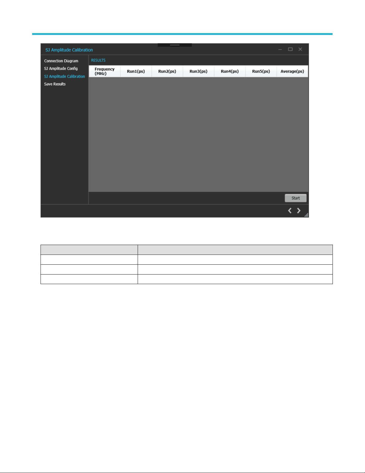
3. SJ Amplitude Calibration:
PCIe PLL BW Transmitter Test Application Help 17
Page 18
Application panels
Figure 9: SJ Amplitude Calibration-SJ Amplitude Calibration
Table 9: SJ Amplitude Calibration
Parameter Description
Frequency(MHz) Displays the frequency at which SJ Amplitude calibration was performed
Run#(ps) Displays the calibrated SJ amplitude for the given frequency
Average(ps) Displays the average of the calibrated SJ amplitude across all runs
4. Save Results: This page allows you to save all the SJ Amplitude calibration results.
PCIe PLL BW Transmitter Test Application Help 18
Page 19

Application panels
Figure 10: SJ Amplitude Calibration-Save Results
Table 10: SJ Amplitude Calibration: Save Results
Parameter Description
Unique ID Enter the Unique ID of the calibrated equipment in the text box.
Generated By Enter the user name in the text box.
Comments Enter the required comments in the comment box (optional).
Save Click to save the results.
Click to complete the SJ Apmlitude calibration and close the wizard.
Upon completion of the SJ Amplitude calibration process or in the event of cancellation of the process, the BERT data
Note:
generator will be turned off automatically by the TekRxTest application.
Tests panel
PLL BW Test
To test how much SJ passes through the DUT's Tx PLL for a certain SJ tone, you need to perform the SJ Amplitude calibration for the
required tones ranging from 0.04 MHz to 23 MHz with a maximum of 100 different tones.
The Frequency Interval Settings lists the frequencies calibrated during SJ Amplitude Calibration.
PCIe PLL BW Transmitter Test Application Help 19
Page 20

Application panels
PLL BW Test procedure
Click PLL BW Test under the Tests panel to view the previously run calibration reports. Click at the right end corner of the application,
to launch the PLL BW test wizard. This wizard will guide you through the sequential procedure to perform the test.
1. Calibration Selection: This page allows you to select the calibration file from the drop-down list.
Figure 11: PLL BW Test-Calibration Selection
Click to move to the next screen.
2. Connection Diagram: This page displays the connection diagram for the PLL BW test.
PCIe PLL BW Transmitter Test Application Help 20
Page 21

Application panels
Figure 12: PLL BW Test-Connection Diagram
Click to move to the next screen.
3. PLL BW Test Configuration: This page allows you to view the configurations and tones used during the selected SJ Amplitude
calibration. You can also configure the DUT Power upon connecting Z2025A PCIe CBB Controller to BERT.
Figure 13: PLL BW Test-Configure Test
PCIe PLL BW Transmitter Test Application Help 21
Page 22

Application panels
Table 11: PLL BW Test-Configure Test
Parameter Description
SJ Amplitude Displays the amplitude for sinusoidal jitter for chosen tones in UI p-p (Range: 0-1 UI
Samples for Averaging
Frequency Interval Settings
Frequency Interval # Displays the current frequency interval.
Start Frequency Displays the starting frequency for each interval in the chosen calibration file.
Stop Frequency Displays the last frequency for a given frequency interval in the chosen calibration file.
# Frequencies Displays the number of frequencies for which the calibration was performed for the given
Frequency (MHz) Displays the list of all generated frequencies for which the calibration was perfomed.
DUT Power Options
External Click on it to manually configure the DUT transmitter for the desired preset and
CBB Controller Click on it to automate the process of transmitting the signal with selected preset for the
Software Equalization Check on it to apply a CTLE filter on the signal during runtime
p-p).Displays the number of runs used for averaging in the chosen calibration file.
interval.
generation.
configured DUT generation
Auto Toggle
Power Cycle Waiting Configure the waiting time to power cycle the DUT.
Preset Choose the preset for which the PLL BW test will be
performed.
Default This will apply a predefined CTLE filter file during waveform
acquisition (only applicable for Gen5)
Custom User can browse and apply CTLE filter file which will be
applied during waveform acquisition
Table 12: Manual toggle pattern
Toggle Sequence Compliance Pattern from the DUT Data Rate (GT/s)
Power ON Gen1 2.5
1 Gen2-3.5 dB 2.5
2 Gen2-6.0 dB 5
3 Gen3-P0 5
4 Gen3-P1 8
5 Gen3-P2 8
6 Gen3-P3 8
7 Gen3-P4 8
8 Gen3-P5 8
9 Gen3-P6 8
10 Gen3-P7 8
Table continued…
PCIe PLL BW Transmitter Test Application Help 22
Page 23

Application panels
Toggle Sequence Compliance Pattern from the DUT Data Rate (GT/s)
11 Gen3-P8 8
12 Gen3-P9 8
13 Gen3-P10 8
14 Gen4-P0 16
15 Gen4-P1 16
16 Gen4-P2 16
17 Gen4-P3 16
18 Gen4-P4 16
19 Gen4-P5 16
20 Gen4-P6 16
21 Gen4-P7 16
22 Gen4-P8 16
23 Gen4-P9 16
24 Gen4-P10 16
25 Jitter Measurement Pattern on all Lanes 16
26 Jitter Measurement Pattern on Lanes 0/8/16/24 and Compliance pattern on all
other Lanes
27 Jitter Measurement Pattern on Lanes 1/8/16/24 and Compliance pattern on all
other Lanes
28 Jitter Measurement Pattern on Lanes 2/8/16/24 and Compliance pattern on all
other Lanes
29 Jitter Measurement Pattern on Lanes 3/8/16/24 and Compliance pattern on all
other Lanes
30 Jitter Measurement Pattern on Lanes 4/8/16/24 and Compliance pattern on all
other Lanes
31 Jitter Measurement Pattern on Lanes 5/8/16/24 and Compliance pattern on all
other Lanes
32 Jitter Measurement Pattern on Lanes 6/8/16/24 and Compliance pattern on all
other Lanes
33 Jitter Measurement Pattern on Lanes 7/8/16/24 and Compliance pattern on all
other Lanes
34 Gen5-P0 32
35 Gen5-P1 32
36 Gen5-P2 32
37 Gen5-P3 32
38 Gen5-P4 32
39 Gen5-P5 32
40 Gen5-P6 32
41 Gen5-P7 32
Table continued…
16
16
16
16
16
16
16
16
PCIe PLL BW Transmitter Test Application Help 23
Page 24

Application panels
Toggle Sequence Compliance Pattern from the DUT Data Rate (GT/s)
42 Gen5-P8 32
43 Gen5-P9 32
44 Gen5-P10 32
4. PLL BW Test: This page displays a graphical representation of the PLL BW test result. It includes a result table tab which displays the
PLL BW test results in a tabular format.
Table 13: PLLBW Test
Parameter Description
Frequency(MHz) Displays the frequency at which SJ Amplitude calibration was performed
Run#(ps) Displays the calibrated SJ amplitude for the given frequency
CalAverage(ps) Displays the average of the calibrated SJ amplitude from the chosen calibration file
Average(ps) Displays the average of the tested SJ amplitude across all runs
Final Value 20log(Average/CalAverage)
Start Click Start to run the measurement.
Cancel Click Cancel to stop the measurement.
Figure 14: PLL BW Test-Run Test
Click to move to the next screen.
5. Save Results: This page allows you to save the PLL BW test results.
PCIe PLL BW Transmitter Test Application Help 24
Page 25

Application panels
Figure 15: PLL BW Test-Save Results
Table 14: PLL BW Test: Save Results
Parameter Description
Unique ID Enter the Unique ID of the calibrated equipment in the text box.
Generated By Enter the user name in the text box.
Comments Enter the required comments in the comment box (optional).
Save Click to save the results.
Click to complete the PLL BW test and close the wizard.
PCIe PLL BW Transmitter Test Application Help 25
Page 26

Programmatic interface commands
PLLBWTEST:APPLYSOFTEQ<1/0>
Indicates if Software Equalization has been applied.
Syntax
PLLBWTEST:APPLYSOFTEQ<1/0>
Inputs
<0|1>
0 - Software Equalization Applied
1 - Software Equalization not Applied
Outputs
<0 | 1>
PLLBWTEST:FILTERFILE <String>
Programmatic interface commands
Indicates the Filter File path when the Software Equalization chosen is custom.
Syntax
PLLBWTEST:FILTERFILE <String>
Inputs
<0|1>
0 - Software Equalization Applied
1 - Software Equalization not Applied
Outputs
<0 | 1>
PLLBWTEST:WIZARD:OPEN
This command opens the PLL BW test wizard.
Syntax
PLLBWTEST:WIZARD:OPEN
Inputs
NA
Outputs
NA
PCIe PLL BW Transmitter Test Application Help 26
Page 27

PLLBWTEST:WIZARD:CLOSE
This command closes the PLL BW test wizard.
Syntax
PLLBWTEST:WIZARD:CLOSE
Inputs
NA
Outputs
NA
PLLBWTEST:SJAMPLITUDE
This command queries the SJ Amplitude configured for the PLLBW test.
Syntax
PLLBWTEST:SJAMPLITUDE
Programmatic interface commands
Inputs
NA
Outputs
<double>
PLLBWTEST:SHOW:CONNECTIONDIAGRAM
This command navigates to the connection diagram in PLL BW test.
Syntax
PLLBWTEST:SHOW:CONNECTIONDIAGRAM
Inputs
NA
Outputs
NA
PLLBWTEST:SAVE:STATUS
This command queries the result's save status.
Syntax
PLLBWTEST:SAVE:STATUS?
Inputs
NA
PCIe PLL BW Transmitter Test Application Help 27
Page 28

Outputs
<string>
PLLBWTEST:SAVE:ID
This command sets or queries the Unique Id for saving the result
Syntax
PLLBWTEST:SAVE:ID <string>
PLLBWTEST:SAVE:ID?
Inputs
<string>
Outputs
<string>
PLLBWTEST:SAVE:GENERATEDBY
Programmatic interface commands
This command sets or queries the Generated By input for saving the result.
Syntax
PLLBWTEST:SAVE:GENERATEDBY <string>
PLLBWTEST:SAVE:GENERATEDBY?
Inputs
<string>
Outputs
<string>
PLLBWTEST:SAVE:COMMENTS
This command sets or queries the Comments for saving the result.
Syntax
PLLBWTEST:SAVE:COMMENTS <string>
PLLBWTEST:SAVE:COMMENTS?
Inputs
<string>
Outputs
<string>
PCIe PLL BW Transmitter Test Application Help 28
Page 29

PLLBWTEST:SAVE
This command saves the PLL BW test result.
Syntax
PLLBWTEST:SAVE
Inputs
NA
Outputs
NA
PLLBWTEST:SAMPLESFORAVERAGE
This command queries the Samples for average configured for the PLLBW test
Syntax
PLLBWTEST:SAMPLESFORAVERAGE?
Programmatic interface commands
Inputs
<int>
Outputs
<int>
PLLBWTest:SOFTWAREQTYPE <0/1>
Indicates the type of Software Equalization applied.
Syntax
PLLBWTest:SOFTWAREQTYPE <0/1>
Inputs
<0|1>
0 - indicates the Software Equalization chosen is Default
1 - indicates the Software Equalization chosen is Custom
Outputs
<0 | 1>
PLLBWTEST:RUNSTATUS
This command queries the PLL BW test run status.
Syntax
PLLBWTEST:RUNSTATUS?
PCIe PLL BW Transmitter Test Application Help 29
Page 30

Inputs
NA
Outputs
<InProgress|Done>
PLLBWTEST:RUN
This command starts or cancels the PLL BW test.
Syntax
PLLBWTEST:RUN <0 | 1>
Inputs
<0 | 1>
0 - Starts the PLL BW test
1 - Cancels the PLL BW test
Outputs
Programmatic interface commands
NA
PLLBWTEST:RESULT:FINALVALUE
This command queries the FinalValue of the different calibration run results.
Syntax
PLLBWTEST:RESULT:FINALVALUE?
Inputs
NA
Outputs
<string>
PLLBWTEST:RESULT:DISPLAYTYPE
This command sets the result view as Chart or Table.
Syntax
PLLBWTEST:RESULT:DISPLAYTYPE <0 |1>
PLLBWTEST:RESULT:DISPLAYTYPE?
Inputs
<0 | 1>
0 - Chart view
1 - Table view
PCIe PLL BW Transmitter Test Application Help 30
Page 31

Outputs
<0 | 1>
0 - Chart view
1 - Table view
PLLBWTEST:RESULTCAL:AVERAGES
This command queries the CalAverages of the different calibration run results.
Syntax
PLLBWTEST:RESULTCAL:AVERAGES?
Inputs
NA
Outputs
<string>
Programmatic interface commands
PLLBWTEST:RESULT:AVERAGES
This command queries the average of the different Calibration run results.
Syntax
PLLBWTEST:RESULT:AVERAGES?
Inputs
NA
Outputs
<string>
PLLBWTEST:OPEN
This command selects the in the Tests tab.
Syntax
PLLBWTEST:OPEN
Inputs
NA
Outputs
NA
PLLBWTEST:FREQUENCY
This command queries the number of frequency value.
PCIe PLL BW Transmitter Test Application Help 31
Page 32

Syntax
PLLBWTEST:FREQUENCY <INTERVAL>?
Inputs
<Interval> Frequency Interval #
Outputs
<int>
PLLBWTEST:FREQ:STOP
This command queries the Stop Frequency value.
Syntax
PLLBWTEST:FREQ:STOP <INTERVAL>?
Inputs
<Interval> Frequency Interval #
Outputs
Programmatic interface commands
<double>
PLLBWTEST:FREQ:START
This command queries the Start Frequency value.
Syntax
PLLBWTEST:FREQ:START <INTERVAL>?
Inputs
<Interval> Frequency Interval #
Outputs
<double>
PLLBWTEST:DUTPOWERTYPE
This command switches between the DUT power options (CBB or External).
Syntax
PLLBWTEST:DUTPOWERTYPE <0 | 1>
PLLBWTEST:DUTPOWERTYPE?
Inputs
<0 | 1>
0 - CBB
1 - External
PCIe PLL BW Transmitter Test Application Help 32
Page 33

Outputs
<0 | 1>
PLLBWTEST:CBBAUTOTOGGLE:WAITTIME
This command sets or queries the Power Cycle waiting time for CBB Auto Toggle.
Syntax
PLLBWTEST:CBBAUTOTOGGLE:WAITTIME <int>
PLLBWTEST:CBBAUTOTOGGLE:WAITTIME?
Inputs
<int>
Outputs
<int>
PLLBWTEST:CBBAUTOTOGGLE:PRESET
Programmatic interface commands
This command sets or queries the BER Pattern.
Syntax
PLLBWTEST:CBBAUTOTOGGLE:PRESET <INDEX>
Inputs
<int>
Outputs
<int>
PLLBWTEST:CALSEL
This command sets or queries the calibration file from combo-box.
Syntax
PLLBWTEST:CALSEL <CALNAME>
Inputs
<CALNAME>
Outputs
<CALNAME>
PLLBWTEST:ALLFREQUENCIES
This command queries information for all frequencies.
PCIe PLL BW Transmitter Test Application Help 33
Page 34

Syntax
PLLBWTEST:ALLFREQUENCIES?
Inputs
NA
Outputs
<string> returns all frequencies as string
SETTINGS:STANDARD
This command sets or queries the standard for PLL test.
Syntax
SETTINGS:STANDARD <0 | 1 | 2>
SETTINGS:STANDARD?
Inputs
<int> - Range 0 to 2
Programmatic interface commands
• 0 - PCIe3
• 1 - PCIe4
• 2 - PCIe5
Outputs
<int> - Range 0 to 2
• 0 - PCIe3
• 1 - PCIe4
• 2 - PCIe5
SETTINGS:RTS:SAMPLERATE
This command sets or queries the sample rate of Real Time Oscilloscope.
Syntax
SETTINGS:RTS:SAMPLERATE <int>
SETTINGS:RTS:SAMPLERATE?
Inputs
<int> - Range: 50 to 200 GS/s
Outputs
<int> - Range: 50 to 200 GS/s
SETTINGS:RTS:POSITIVECHANNEL
This command sets or queries the Real Time Oscilloscope setting for positive channel.
PCIe PLL BW Transmitter Test Application Help 34
Page 35

Syntax
SETTINGS:RTS:POSITIVECHANNEL <int>
SETTINGS:RTS:POSITIVECHANNEL?
Inputs
<int> - Range: 0 to 3
• 0 - CH1
• 1 - CH2
• 2- CH3
• 3 - CH4
Outputs
<int> - Range: 0 to 3
• 0 - CH1
• 1 - CH2
• 2- CH3
• 3 - CH4
Programmatic interface commands
SETTINGS:RTS:NEGATIVECHANNEL
This command sets or queries the Real Time Oscilloscope setting for negative channel.
Syntax
SETTINGS:RTS:NEGATIVECHANNEL <int>
SETTINGS:RTS:NEGATIVECHANNEL?
Inputs
<int> - Range: 0 to 3
• 0 - CH1
• 1 - CH2
• 2- CH3
• 3 - CH4
Outputs
<int> - Range: 0 to 3
• 0 - CH1
• 1 - CH2
• 2- CH3
• 3 - CH4
SJAMPCAL:ALLFREQUENCIES
This command reads all the frequencies.
PCIe PLL BW Transmitter Test Application Help 35
Page 36

Syntax
SJAMPCAL:ALLFREQUENCIES?
Inputs
NA
Outputs
<string>
SJAMPCAL:FREQ:START
This command reads or writes the start frequency value.
Syntax
SJAMPCAL:FREQ:START <INTERVAL> <VALUE>
SJAMPCAL:FREQ:START <INTERVAL>?
Inputs
<Interval> Frequency Interval #
Programmatic interface commands
<double>
Outputs
<double>
SJAMPCAL:FREQ:STOP
This command reads or writes the stop frequency value.
Syntax
SJAMPCAL:FREQ:STOP <INTERVAL> <VALUE>
SJAMPCAL:FREQ:STOP <INTERVAL>?
Inputs
<Interval> Frequency Interval #
<double>
Outputs
<double>
SJAMPCAL:FREQUENCIES:DEFAULT
This command sets SJ Amplitude to default frequency settings.
Syntax
SJAMPCAL:FREQUENCIES:DEFAULT
PCIe PLL BW Transmitter Test Application Help 36
Page 37

Inputs
NA
Outputs
NA
SJAMPCAL:FREQUENCY
This command reads or writes the number of frequency value.
Syntax
SJAMPCAL:FREQUENCY <INTERVAL> <value>
SJAMPCAL:FREQUENCY <INTERVAL>?
Inputs
<Interval> Frequency Interval #
<int>
Outputs
Programmatic interface commands
<int>
SJAMPCAL:FREQUENCYINTERVALS
This command reads or writes the number of frequency intervals value.
Syntax
SJAMPCAL:FREQUENCYINTERVALS <value>
SJAMPCAL:FREQUENCYINTERVALS?
Inputs
<int>
Outputs
<int>
SJAMPCAL:OPEN
This command opens the SJ Amplitude calibration page.
Syntax
SJAMPCAL:OPEN
Inputs
NA
Outputs
NA
PCIe PLL BW Transmitter Test Application Help 37
Page 38

SJAMPCAL:RESULT
This command gets the specified calibration run results.
Syntax
SJAMPCAL:RESULT <Index of Run #>?
Inputs
<int> - Index of Run #
Outputs
<double>
SJAMPCAL:RESULT:AVERAGES
This command gets the average of the different Calibration run Results.
Syntax
SJAMPCAL:RESULT:AVERAGES?
Programmatic interface commands
Inputs
NA
Outputs
<string>
SJAMPCAL:RESULT:FREQAVG
This command gets the average of the calibration run results for specific frequency.
Syntax
SJAMPCAL:RESULT:FREQAVG <FREQ>?
Inputs
<FREQ>
Outputs
<double>
SJAMPCAL:RUN
This command runs or cancels the PLL BW SJ Amplitude calibration.
Syntax
SJAMPCAL:RUN <0|1>
Inputs
<0|1>
0 - Stop the SJ Amplitude test run.
PCIe PLL BW Transmitter Test Application Help 38
Page 39

1 - Start the SJ Amplitude test run.
Outputs
NA
SJAMPCAL:RUNSTATUS
This command gets the PLL BW SJ Amplitude calibration run status.
Syntax
SJAMPCAL:RUNSTATUS?
Inputs
NA
Outputs
{InProgress | Done}
SJAMPCAL:RESULT:AVERAGES
Programmatic interface commands
This command gets the average of the different dalibration run results.
Syntax
SJAMPCAL:RESULT:AVERAGES?
Inputs
NA
Outputs
NA
SJAMPCAL:SAVE
This command saves the calibration result.
Syntax
SJAMPCAL:SAVE
Inputs
NA
Outputs
NA
SJAMPCAL:SAVE:COMMENTS
This command sets or gets the save comment.
PCIe PLL BW Transmitter Test Application Help 39
Page 40

Syntax
SJAMPCAL:SAVE:COMMENTS <Comments>
SJAMPCAL:SAVE:COMMENTS?
Inputs
<string>
Outputs
<string>
SJAMPCAL:SAVE:GENERATEDBY
This command sets or gets the name of the person who generated the report.
Syntax
SJAMPCAL:SAVE:GENERATEDBY <string>
SJAMPCAL:SAVE:GENERATEDBY?
Inputs
Programmatic interface commands
<string>
Outputs
<string>
SJAMPCAL:SAVE:ID
This command sets or gets the save Unique ID.
Syntax
SJAMPCAL:SAVE:ID <string>
SJAMPCAL:SAVE:ID?
Inputs
<string>
Outputs
<string>
SJAMPCAL:SAVE:STATUS
This command gets the save status.
Syntax
SJAMPCAL:SAVE:STATUS?
Inputs
NA
PCIe PLL BW Transmitter Test Application Help 40
Page 41

Outputs
<string>
SJAMPCAL:SHOW:CONNECTIONDIAGRAM
This command opens the connection diagram for SJ Amplitude calibration.
Syntax
SJAMPCAL:SHOW:CONNECTIONDIAGRAM
Inputs
NA
Outputs
NA
SJAMPCAL:RESULT:SJAMPLITUDE
This command reads or rrites the SJ amplitude value.
Programmatic interface commands
Syntax
SJAMPCAL:RESULT:SJAMPLITUDE <int>
SJAMPCAL:RESULT:SJAMPLITUDE?
Inputs
NA
Inputs
<string>
Outputs
<string>
SJAMPCAL:WIZARD:CLOSE
This command closes the SJ Amplitude calibration wizard.
Syntax
SJAMPCAL:WIZARD:CLOSE
Inputs
NA
Outputs
NA
PCIe PLL BW Transmitter Test Application Help 41
Page 42

SJAMPCAL:WIZARD:OPEN
This command opens the SJ Amplitude calibration wizard.
Syntax
SJAMPCAL:WIZARD:OPEN
Inputs
NA
Outputs
NA
Programmatic interface commands
PCIe PLL BW Transmitter Test Application Help 42
Page 43

Index
A
Application Help 8
C
calibrations 15
connections panel 12
Contacting Tektronix 8
H
help panel 15
P
PLL BW Test 20
S
settings panel 13
Support 8
T
Technical support 8
TekRxTest 11
|
 Loading...