

Page 1

Keithley Instruments, Inc.
28775 Aurora Road
Cleveland, Ohio 44139
(440) 248-0400
Fax: (440) 248-6168
www.keithley.com
for SM Series solid-state relay modules
Packing List Manual
Introduction
Model PB-24SM 24-channel mounting board
This document provides safety and installation information for the PB-24SM solid-state I/O module mounting board.
Description
The PB-24SM is an industry-standard baseboard that holds 24 SM Series miniature solid-state I/O modules. The PB-24SM connects I/O modules to a Keithley PIO-SSR Series digital I/O board or to a KPCI-3107/3108 analog/digital I/O board (via an intermediate accessory).
Safety summary
WARNING
This product is intended for use by qualified personnel who recognize shock hazards and are familiar with the safety precautions
required to avoid possible injury. Read the operating and safety information carefully before using the product.
Users of this product must be protected from electric shock at all times. The responsible body must ensure that users are prevented access and/or insulated from every connection point.
Do not connect switching boards directly to unlimited power circuits. When connecting sources to switching cards, install protective devices to limit fault current and voltage to the card.
Read and follow the “Safety Precautions” discussed at the end of this manual.
Installation
WARNING
CAUTION
Install your PB-24SM accessory as follows:
Users of this product must be protected from electric shock at all times. The responsible
body must ensure that users are prevented access and/or insulated from every connection
point. In some cases, connections must be exposed to potential human contact. Product
users in these circumstances must be trained to protect themselves from the risk of electric shock.
Ensure that the computer power is turned OFF before installing the PB-24SM. Connecting the PB-24SM to the computer while the power is ON can damage your computer, the accessory, or both.
1. Shut down and turn OFF your computer, and turn OFF power to any circuits that are connected to the PB-24SM accessory.
PA-699 Rev. B / 6-02
Page 2
2
•
•
2. Connect the PB-24SM accessory to your PIO-SSR Series board, KPCI-3107 board, or KPCI-3108 board as in Figure 1.
Figure 1
Connecting the PB-24SM to PIO-SSR, KPCI-3107, and KPCI-3108 boards
PIO-SSR-12 at 50-pin header,
PIO-SSR-24 at one of two 50-pin headers, or
PIO-SSR-120 at one of five 50-pin headers
KPCI-3107
or KPCI-3108 at “Digital”
(bottom) connector
CAB-1284CC cable
——
——
CAB-SSR cable
STA-3108-D1
——
accessory
PB-24SM board-
——
edge connector
——
CAB-SSR cable
PB-24SM board-
——
edge connector
3. Inventory the spare current available at the computer +5V power bus. The spare current is the remaining current capacity
that is not already used by the computer and all installed boards, including the PIO-SSR or KPCI-3107/3108 board.
4. Compare the spare current available at the computer +5V power bus with the total current required by the PB-24SM and
all modules that will be installed therein.
If the spare current available at the computer +5V power bus does not exceed the total current required by the PB-24SM
and all modules that will be installed—within a reasonable safety margin—do the following:
a. Move the replaceable 1A fuse (Little Fuse 251001 or equivalent) to the position that is closest to the external-power
terminal block. See Figure 2. This action disconnects the PB-24SM accessory from the computer +5V power bus
and connects it to the external-power terminal block.
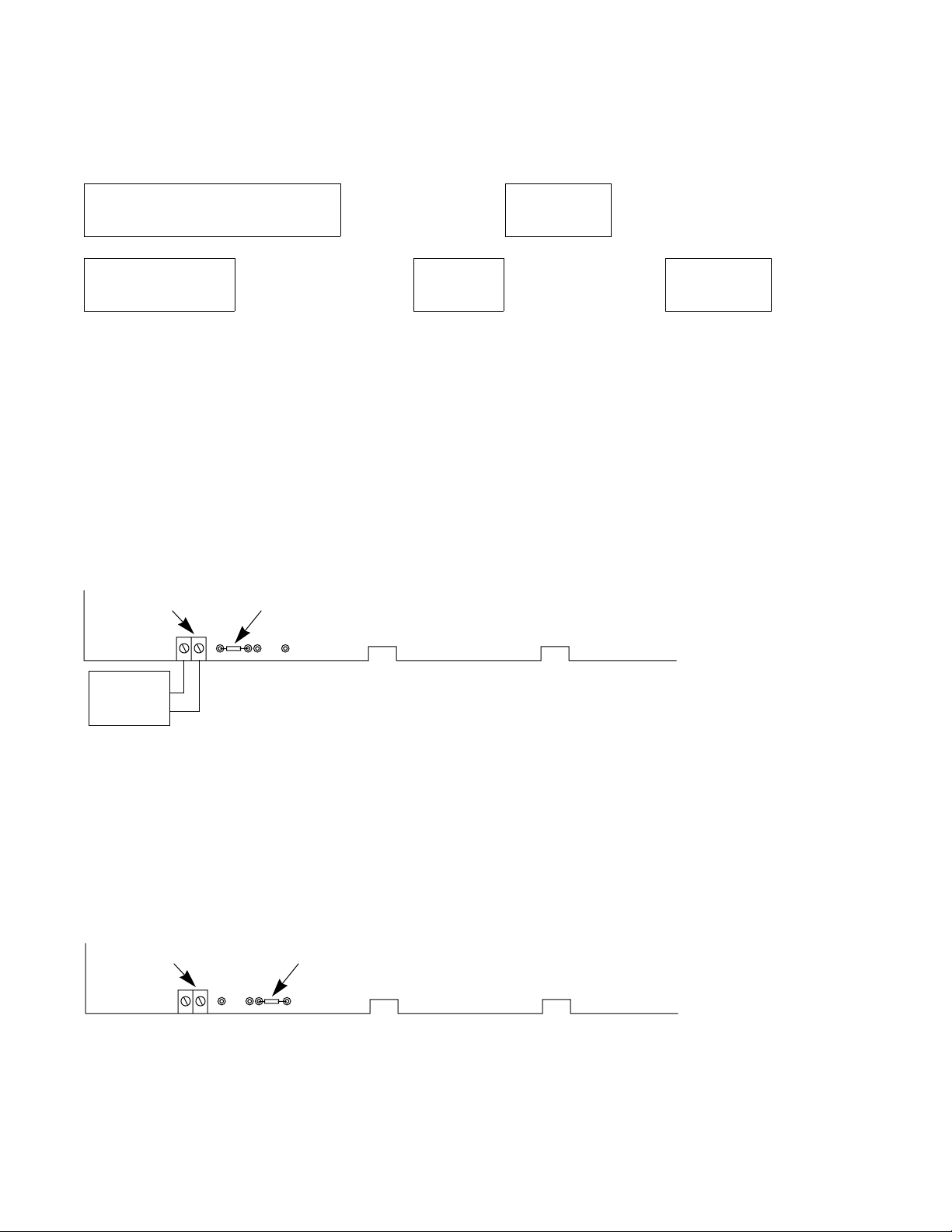
Figure 2
Powering the PB-24SM from an external +5V power supply
External-
Powe r
Terminal Block
+
Replaceable 1A Fuse in
External-Power Position
PB-24SM Accessory
External
+5V Power
Supply
+
b. Connect an unpowered (switch OFF) +5V power supply to the external power terminal block, ensuring that you
observe correct polarity. See Figure 2.
If the spare current available at the computer +5V power bus exceeds the total current required by the PB-24SM and
all modules that will be installed—within a reasonable safety margin—do the following: move the replaceable 1A fuse
(Little Fuse 251001 or equivalent) to the position that is furthest from the external power terminal block. See Figure 3.
This action connects the PB-24SM accessory to the computer +5V power bus.
Figure 3
Powering the PB-24SM from the computer +5V power bus
External-
Powe r
Terminal Block
+
Replaceable 1A Fuse in
Computer-Power-Bus
Position
PB-24SM Accessory
5. Install modules in the PB-24SM according to Table 1, installing only input modules for ports that will be configured as
input ports and only output modules for ports that will be configured as output ports.
Page 3

3
CAUTION
Install only input modules or only output modules for all bits of any given port (port
A, B, or C for the KPCI-3107/3108; port A, B, C-lower, or C-upper for the PIO-SSR.)
The port configuration determines whether input or output modules must be installed.
For example, if port B is configured as an output port, the modules for bits PB0,
PB1,... PB6, and PB7 must all be output modules. Failure to match all modules for a
given port to the port configuration may result in damage to the PB-24SM, to the connected I/O board, or to both.
6. Wire your external circuits to the PB-24SM screw terminals according to Table 1, based on the input and output modules
that you have installed.
Table 1
Correspondence between modules, wiring terminals, connector pins, and digital-I/O ports
Module
number
Screw terminals connected to the
external-circuit side of this module
Screw terminal
connected to pin
1 of module
Screw terminal
connected to pin
2 of module
Connector pins connected to the
PIO-SSR or KPCI-3107/3108 side of
this module (at module pin 4
At the PB-24SM
end of the CABSSR cable (boardedge connector
At the 50-pin
header end of
the CAB-SSR
cable
Corresponding digital-I/O bits at
the PIO-SSR or
1
)
KPCI-3107/3108 board
At the
PIO-SSR
board
At the
KPCI-3107/3108
board
0 1 2 47 47 PA0 PB0
1 3 4 45 45 PA1 PB1
2 5 6 43 43 PA2 PB2
3 7 8 41 41 PA3 PB3
4 9 10 39 39 PA4 PB4
5 11 12 37 37 PA5 PB5
6 13 14 35 35 PA6 PB6
7 15 16 33 33 PA7 PB7
8 17 18 31 31 PB0 PC0
9 19 20 29 29 PB1 PC1
10 21 22 27 27 PB2 PC2
11 23 24 25 25 PB3 PC3
12 25 26 23 23 PB4 PD4
13 27 28 21 21 PB5 PD5
14 29 30 19 19 PB6 PD6
15 31 32 17 17 PB7 PD7
16 33 34 15 15 PC0 PA0
17 35 36 13 13 PC1 PA1
18 37 38 11 11 PC2 PA2
19 39 40 9 9 PC3 PA3
20 41 42 7 7 PC4 PA4
21 43 44 5 5 PC5 PA5
22 45 46 3 3 PC6 PA6
23 47 48 1 1 PC7 PA7
1
Pin 4 of each module inputs/outputs the digital I/O signal to/from the module. Pin 4 is also connected to a 3.3k Ω pull-up resistor, which is in turn
connected to +5V power.
Page 4

4
Table 2 indicates how +5V power and the digital ground is connected to the PB-24SM accessory and its installed modules.
Table 2
Correspondence between +5V power and digital grounds, connector pins, and module pins
Connector pins connected to computer
+5V power and digital ground
from the computer power bus
(through the connected PIO-SSR,
KPCI-3107, or KPCI-3108 board)
+5V power bus and digital ground
At the 50-pin
header end of the
CAB-SSR cable
At the PB-24SM end of
the CAB-SSR cable
(board-edge connector)
+5V power Pin 49 Pin 49 Pin 3, through LED
1
Pins of each module wired to +5V
power and digital ground
2
Pin 4, through 3.3k Ω pull-up resistor
Digital ground All even-numbered
All even-numbered pins
Pin 5, directly
pins
1
Alternatively, the PB-24SM can be hardware-configured such that +5V power is supplied from an external power supply. Refer to step 4 of the
procedure above.
2
The LED lights when the module has been actuated.
Safety Precautions
The following safety precautions should be observed before using this product and any associated instrumentation. Although some instruments and accessories would normally be used with non-hazardous voltages, there are situations where hazardous conditions may be present.
This product is intended for use by qualified personnel who recognize shock hazards and are familiar with the safety precautions required to
avoid possible injury. Read and follow all installation, operation, and maintenance information carefully before using the product. Refer to
the manual for complete product specifications.
If the product is used in a manner not specified, the protection provided by the product may be impaired.
The types of product users are:
Responsible body is the individual or group responsible for the use and maintenance of equipment, for ensuring that the equipment is operated
within its specifications and operating limits, and for ensuring that operators are adequately trained.
Operators use the product for its intended function. They must be trained in electrical safety procedures and proper use of the instrument. They
must be protected from electric shock and contact with hazardous live circuits.
Maintenance personnel perform routine procedures on the product to keep it operating properly, for example, setting the line voltage or re-
placing consumable materials. Maintenance procedures are described in the manual. The procedures explicitly state if the operator may perform them. Otherwise, they should be performed only by service personnel.
Service personnel are trained to work on live circuits, and perform safe installations and repairs of products. Only properly trained service
personnel may perform installation and service procedures.
Keithley products are designed for use with electrical signals that are rated Installation Category I and Installation Category II, as described
in the International Electrotechnical Commission (IEC) Standard IEC 60664. Most measurement, control, and data I/O signals are Installation
Category I and must not be directly connected to mains voltage or to voltage sources with high transient over-voltages. Installation Category
II connections require protection for high transient over-voltages often associated with local AC mains connections. Assume all measurement,
control, and data I/O connections are for connection to Category I sources unless otherwise marked or described in the Manual.
Exercise extreme caution when a shock hazard is present. Lethal voltage may be present on cable connector jacks or test fixtures. The American National Standards Institute (ANSI) states that a shock hazard exists when voltage levels greater than 30V RMS, 42.4V peak, or 60VDC
are present. A good safety practice is to expect that hazardous voltage is present in any unknown circuit before measuring.
Operators of this product must be protected from electric shock at all times. The responsible body must ensure that operators are prevented
access and/or insulated from every connection point. In some cases, connections must be exposed to potential human contact. Product operators in these circumstances must be trained to protect themselves from the risk of electric shock. If the circuit is capable of operating at or
above 1000 volts, no conductive part of the circuit may be exposed.
Do not connect switching cards directly to unlimited power circuits. They are intended to be used with impedance limited sources. NEVER
connect switching cards directly to AC mains. When connecting sources to switching cards, install protective devices to limit fault current and
voltage to the card.
Page 5

Before operating an instrument, make sure the line cord is connected to a properly grounded power receptacle. Inspect the connecting cables,
test leads, and jumpers for possible wear, cracks, or breaks before each use.
When installing equipment where access to the main power cord is restricted, such as rack mounting, a separate main input power disconnect
device must be provided, in close proximity to the equipment and within easy reach of the operator.
For maximum safety, do not touch the product, test cables, or any other instruments while power is applied to the circuit under test. ALWAYS
remove power from the entire test system and discharge any capacitors before: connecting or disconnecting cables or jumpers, installing or
removing switching cards, or making internal changes, such as installing or removing jumpers.
Do not touch any object that could provide a current path to the common side of the circuit under test or power line (earth) ground. Always make
measurements with dry hands while standing on a dry, insulated surface capable of withstanding the voltage being measured.
The instrument and accessories must be used in accordance with its specifications and operating instructions or the safety of the equipment
may be impaired.
Do not exceed the maximum signal levels of the instruments and accessories, as defined in the specifications and operating information, and
as shown on the instrument or test fixture panels, or switching card.
When fuses are used in a product, replace with same type and rating for continued protection against fire hazard.
Chassis connections must only be used as shield connections for measuring circuits, NOT as safety earth ground connections.
If you are using a test fixture, keep the lid closed while power is applied to the device under test. Safe operation requires the use of a lid interlock.
If or is present, connect it to safety earth ground using the wire recommended in the user documentation.
!
The symbol on an instrument indicates that the user should refer to the operating instructions located in the manual.
The symbol on an instrument shows that it can source or measure 1000 volts or more, including the combined effect of normal and common mode voltages. Use standard safety precautions to avoid personal contact with these voltages.
The WARNING heading in a manual explains dangers that might result in personal injury or death. Always read the associated information
very carefully before performing the indicated procedure.
The CAUTION heading in a manual explains hazards that could damage the instrument. Such damage may invalidate the warranty.
Instrumentation and accessories shall not be connected to humans.
Before performing any maintenance, disconnect the line cord and all test cables.
To maintain protection from electric shock and fire, replacement components in mains circuits, including the power transformer, test leads,
and input jacks, must be purchased from Keithley Instruments. Standard fuses, with applicable national safety approvals, may be used if the
rating and type are the same. Other components that are not safety related may be purchased from other suppliers as long as they are equivalent
to the original component. (Note that selected parts should be purchased only through Keithley Instruments to maintain accuracy and functionality of the product.) If you are unsure about the applicability of a replacement component, call a Keithley Instruments office for information.
To clean an instrument, use a damp cloth or mild, water based cleaner. Clean the exterior of the instrument only. Do not apply cleaner directly
to the instrument or allow liquids to enter or spill on the instrument. Products that consist of a circuit board with no case or chassis (e.g., data
acquisition board for installation into a computer) should never require cleaning if handled according to instructions. If the board becomes
contaminated and operation is affected, the board should be returned to the factory for proper cleaning/servicing.
5
 Loading...