

Page 1

PA3000
xx
ZZZ
Power Analyzer
User Manual
*P077115201*
077-1152-01
Page 2

Page 3

xx
PA3000
ZZZ
Power Analyzer
User Manual
www.tek.com
077-1152-01
Page 4

Copyright © Tektronix. All rights reserved. Licensed software products are owned by Tektronix or its subsidiaries
or suppliers, and are protected by national copyright laws and international treaty provisions.
Tektronix products are covered by U.S. and foreign patents, issued and pending. Information in this publication
supersedes that in all previously published material. Specifications and price change privileges reserved.
TEKTRONIX and TEK are registered trademarks of Tektronix, Inc.
Contacting Tektronix
Tektronix, Inc.
14150 SW Karl Braun Drive
P.O. B o x 5 0 0
Beaverto
USA
For product information, sales, service, and technical support:
n, OR 97077
In North America, call 1-800-833-9200.
Worldwide, visit www.tek.com to find contacts in your area.
Page 5

Warranty
Tektronix warrants that this product will be free from defects in materials and workmanship for a period of three
(3) years from the date of shipment. If any such product proves defective during this warranty period, Tektronix, at
its option, either will repair the defective product without charge for parts and labor, or will provide a replacement
in exchange for the defective product. Parts, modules and replacement products used by Tektronix for warranty
work may be n
the property of Tektronix.
ew or reconditioned to like new performance. All replaced parts, modules and products become
In order to o
the warranty period and make suitable arrangements for the performance of service. Customer shall be responsible
for packaging and shipping the defective product to the service center designated by Tektronix, w ith shipping
charges prepaid. Tektronix shall pay for the return of the product to Customer if the shipment is to a location within
the country in which the Tektronix service center is located. Customer shall be responsible for paying all shipping
charges, duties, taxes, and any other charges for products returned to any other locations.
This warranty shall not apply to any defect, failure or damage caused by improper use or improper or inadequate
maintenance and care. Tektronix shall not be obligated to furnish service under this warranty a) to repair damage
result
b) to repair damage resulting from improper use or connection to incompatible equipment; c) to repair any damage
or malfunction caused by the use of non-Tektronix supplies; or d) to service a product that has been modified or
integrated with other products when the effect of such modification or integration increases the time or difficulty
of servicing the product.
THIS WARRANTY IS GIVEN BY TEKTRONIX WITH RESPECT TO THE PRODUCT IN LIEU OF ANY
OTHER WARRANTIES, EXPRESS OR IMPLIED. TEKTRONIX AND ITS VENDORS DISCLAIM ANY
IMPLIED WARRANTIES OF MERCHANTABILITY OR FITNESS FOR A PARTICULAR PURPOSE.
TRONIX' RESPONSIBILITY TO REPAIR OR REPLACE DEFECTIVE PRODUCTS IS THE SOLE
TEK
AND EXCLUSIVE REMEDY PROVIDED TO THE CUSTOMER FOR BREACH OF THIS WARRANTY.
TEKTRONIX AND ITS VENDORS WILL NOT BE LIABLE FOR ANY INDIRECT, SPECIAL, INCIDENTAL,
OR CONSEQUENTIAL DAMAGES IRRESPECTIVE OF WHETHER TEKTRONIX OR THE VENDOR HAS
ADVANCE NOTICE OF THE POSSIBILITY OF SUCH DAMAGES.
[W4 – 15AUG04]
btain service under this warranty, Customer must notify Tektronix of the defect before the expiration of
ing from attempts by personnel other than Tektronix representatives to install, repair or service the product;
Page 6

Page 7

Table of Contents
Important safety information ............................. .................................. ..................... vii
General safety summary .................................................................................... vii
Service safety summary...................... ................................ ................................ . x
Terms in this manual ..... ................................ ................................ .................... xi
Symbols and terms on the product.......................................................................... xi
Compliance information ......................................................................................... xii
EMC compliance ................... ................................ ................................ ......... xii
Safety compliance ........................................................................................... xiii
Environmental considerations ............................................................................... xv
Preface ............................................................................................................ xvii
Features and abilities . . . ... . . . .... . . ... . . . .... . . ... . . . .... . . ... . . . .... . . ... . . . .... . . ... . . . .... . . ... . . . .... . . xvii
Getting started..... . ..... . ..... . ..... . .... . . .... . . .... . ..... . ..... . ..... . ..... . ..... . ..... . ..... . ..... . ... . . ..... . ... 1
Before you begin - safety .................. .................................. ................................ . 1
Power on. ................................ .................................. ................................ ..... 2
Concept of global, group, and channel parameters...................................... ................... 3
Connecting to the product under test ........................................................................ 4
Results screen .................................................................................................. 6
Navigating the Results screen ................................................................................ 7
Navigating the menu system.................................................................................. 8
On-screen help ...................... ................................ .................................. ......... 9
Front panel . ................................ .................................. ................................ ...... 11
Front panel controls and connectors .................. .................................. .................... 11
Quick view keys .............................................................................................. 12
Results screen ................................................................................................. 13
Waveform screen.............. .................................. ................................ .............. 14
Bar chart screen ....................... ................................ .................................. ...... 15
Integrator screen .................... .................................. ................................ ........ 17
Vector screen .......................... ................................ .................................. ...... 19
Math screen.................................................................................................... 20
Setup screen ............................. ................................ ................................ ...... 21
Front panel USB port............... ................................ .................................. ........ 22
Soft keys....................................................................................................... 23
Menu and Help keys.......................................................................................... 24
Operational and alphabetical keys .................... ................................ ...................... 24
Number and formula keys ................................................................................... 25
Logging data to a storage device........ ................................ .................................. .. 26
Connecting signals ................ .................................. ................................ .............. 28
Input overview ...................... .................................. ................................ ........ 28
To connect a simple current transformer... ................................ ................................ 30
PA3000 Power Analyzer User Manual i
Page 8

Table of Contents
To connect an ex
To connect a transducer with a voltage output............................................................. 33
To connect a voltage transformer / transducer............................................................. 34
Power for external transducers .............................................................................. 35
The menu system .................................................................................................. 36
Measurements................................................................................................. 36
Measurement Configuration menu.......................................................................... 38
Modes .......................................................................................................... 42
Inputs........................................................................................................... 47
Graphs and waveforms....................................................................................... 53
Interfaces ...................................................................................................... 54
Datalog........................................... ................................ .............................. 56
Math results ................................................................................................... 56
System Configuration ........................................................................................ 59
User Configuration ........... .................................. ................................ .............. 61
Remote operation .................................................................................................. 62
Overview .................. ................................ ................................ .................... 62
Interfacing with RS-232 systems............................................................................ 62
Interfacing with USB systems............................................................................... 62
Interfacing with Ethernet systems........... ................................ ................................ 62
Interfacing with GPIB systems (optional) ................................................................. 63
Status reporting ..................... ................................ .................................. ........ 63
Command listing.............................................................................................. 66
IEEE 488.2 standard commands and status commands .................................................. 67
Channel and group commands .............................................................................. 69
Unit information commands......... ................................ ................................ ........ 70
Measurement selection and reading commands ..................... ................................ ...... 70
Measurement configuration commands .................................................................... 74
Mode setup commands... ................................ ................................ .................... 79
Input setup commands ....................................................................................... 83
Graph and waveform commands........................ ................................ .................... 88
Interface commands .... ................................ .................................. .................... 89
Datalog commands ....... .................................. ................................ .................. 90
Screen save commands......................... ................................ .............................. 91
Math commands ........................ ................................ ................................ ...... 91
System configuration commands............................................................................ 92
User configuration commands..................... ................................ .......................... 95
Sending and receiving commands .......................................................................... 96
Communications examples .. .................................. ................................ .............. 97
PA3000 software....................... ................................ ................................ .......... 100
PWRVIEW PC software ..... .................................. ................................ ............ 100
ternal resistive shunt ................................ .................................. .... 31
ii PA3000 Power Analyzer User Manual
Page 9

Table of Contents
Firmware updat
Application examples ....................... ................................ .................................. .. 103
Example 1: Efficiency testing single phase applications ............................................... 104
Example 2: Efficiency testing three phase applications ........ ................................ ........ 112
Example 3: Energy consumption testing............... ................................ .................. 121
Example 4: Standby power measurements (IEC 62301 Ed. 2.0)........ .............................. 127
Example 5: I
Reference information .......................................................................................... 139
Measured parameters....................................................................................... 139
Accuracy equations......................................................................................... 141
Sum equations............................................................................................... 142
Communication ports....................................................................................... 146
Index
e utility . . ..... . ..... . ... . . . .... . ..... . ..... . ..... . ..... . ..... . ..... . ... . . ..... . ..... . ..... . 101
nrush current testing............. ................................ ............................ 133
PA3000 Power Analyzer User Manual iii
Page 10

Table of Contents
List of Figure
Figure i: Tektronix PA3000 Power Analyzer................................................................. xvii
Figure 1: Typical PA3000 input connections.................................................................... 4
Figure 2: Rear panel input module .............. ................................ ................................. 5
Figure 3: Result screen (four-channel instrument).............................................................. 6
Figure 4: Left and right arrow hard keys ..................... ................................ ................... 7
Figure 5: Front panel controls and connectors ................................................................. 11
Figure 6: Quick view keys ......... ................................ ................................ .............. 12
Figure 7: Results screen .......................................................................................... 13
Figure 8: Waveform screen....................................................................................... 14
Figure 9: Bar chart screen ........ ................................ .................................. .............. 15
Figure 10: Integrator screen.................. ................................ .................................. .. 17
Figure 11: Vector screen .......................................................................................... 19
Figure 12: Math screen ........................................................................................... 20
Figure 13: Setup screen (first screen) ........................................................................... 21
Figure 14: Setup screen (second screen)........................................................................ 22
Figure 15: Operational and alphabet keys ............................ ................................ .......... 24
Figure 16: Example data file ..................................................................................... 27
Figure 17: Signal inputs on rear panel (Channel 1 shown) ................................................... 28
Figure 18: Current transformer connections............................ .................................. ...... 30
Figure 19: External resistive shunt connections ............................................................... 31
Figure 20: Current transformer connections............................ .................................. ...... 34
Figure 21: External resistive shunt connections ............................................................... 35
Figure 22: Measurements screen ................................................................................ 36
Figure 23: Example of a moved measurement ................................................................. 38
Figure 24: Measurement Configuration menu ....... .................................. ........................ 38
Figure 25: Single-phase, two-wire and DC measurements. Select 1 phase, 2 wire mode.. . ..... . ..... . .. 47
Figure 26: Single-
Figure 27: Three-phase, three-wire (2 Wattmeter method). Select 3 phase, 3 wire............ ............ 48
Figure 28: Three phase, three wire (3 Wattmeter method). Select 3 phase, 3 wire (3V3A)............... 48
Figure 29: Three-phase, three-wire (3 Wattmeter method). Select 3 phase, 4 wire............ ............ 49
Figure 30: Three-phase, four-wire (3 Wattmeter method). Select 3 phase, 4 wire..... .................... 49
Figure 31: Status byte............................................................................................. 63
Figure 32: Status byte register ................................................................................... 64
Figure 33: Display Data Status Register ........................................................................ 64
Figure 34: Display Data Status Enable Register....... ................................ ........................ 64
Figure 35: Standard Event Status Register ........... ................................ .......................... 65
Figure 36: Standard Event Status Enable Register ............................................................ 65
Figure 37: PWRVIEW software . ................................ ................................ .............. 100
s
phase, three-wire. Select 1 phase, 3 wire.................................................. 48
iv PA3000 Power Analyzer User Manual
Page 11

Table of Contents
Figure 38: AC-D
Figure 39: Efficiency measurement on the PA3000 ......................................................... 105
Figure 40: Harmonic bar chart on the PA3000... ................................ ............................ 108
Figure 41: Efficiency measurement with the PWRVIEW software............ ............................ 108
Figure 42: Efficiency Trend Chart............................................................................. 110
Figure 43: Logging setup....................................................................................... 111
Figure 44: C
Figure 45: PWM motor drive efficiency (1 phase in and 3 phase out) .. ................................ .. 114
Figure 46: Vector graph on the PA3000....................................................................... 116
Figure 47: PWM Motor drive efficiency (3 phase in and 3 phase out).................................... 117
Figure 48: Auxiliary inputs setup for torque and speed measurements . .... . . .... . ..... . ..... . ..... . ..... 119
Figure 49: Harmonic bar chart ................................................................................. 120
Figure 5
Figure 51: Energy consumption testing on the PA3000..................................................... 123
Figure 52: Integration Trend chart............................. .................................. .............. 126
Figure 53: Custom Limits .................... ................................ ................................ .. 127
Figure 54: Standby power measurements wiring diagram.................................................. 128
Figure 55: Standby Power mode......................... ................................ ...................... 129
Figu
Figure 57: IEC 62301 Ed. 2.0 Standby power test report................................................... 132
Figure 58: Inrush current measurement wiring diagram .................................................... 134
Figure 59: Min-Max columns for the Inrush current measurement........................................ 135
Figure 60: Inrush current measurement....................................................................... 136
Figure 61: Power analyzer communication ports on the rear panel........................................ 147
0: Energy consumption measurements wiring diagram ........................................... 122
re 56: Full compliance IEC 62301 Standby power test ............ .................................. .. 130
Cefficiency measurement wiring diagram ............................................... 105
ustom limits setup ................................................................................ 112
PA3000 Power Analyzer User Manual v
Page 12

Table of Contents
List of Tables
Table 1: Front panel controls and connectors .................................................................. 11
Table 2: Sig
Table 3: Weighing factors for TIF ............................................................................... 41
Table 4: Effects of frequency range settings in PWM mode. ... . . ..... . ..... . ... . . . .... . ..... . ..... . ..... .... 46
Table 5: Input ranges.............................................................................................. 50
Table 6: Valid channel parameters............. ................................ ................................ .. 57
Table 7: Valid group parameters ................. .................................. .............................. 58
Table 8: V
Table 9: Parameters for returning values from the analog and counter inputs.......... .................... 58
Table 10: Status byte register bit definitions . ..... . ..... . ..... . ..... . ..... . ..... . ..... . ..... . ... . . . .... . . .... . . 64
Table 11: Display data status register bit definitions . . .... . . .... . . .... . . .... . . .... . . .... . . .... . . .... . . .... . . .. 64
Table 12: Display data status enable register bit definitions . . ..... . ..... . ..... . ..... . ..... . ..... . ..... . ..... . 64
Table 13: Standard event status register bit definitions.............. .................................. ........ 65
Table
Table 15: Phase measurements........................................... ................................ ...... 139
Table 16: Measurement accuracy.............................................................................. 141
Table 17: One phase, three wire sum equations............ ................................ .................. 142
Table 18: Three phase, three wire sum equations............ ................................ ................ 143
Table 19: Three phase, four wire sum equations............................................................. 144
ble 20: USB connector pin descriptions............................................ ........................ 146
Ta
Table 21: Communication ports on the rear panel ........... .................................. .............. 147
Table 22: Ethernet pin descriptions...................................... ................................ ...... 148
Table 23: GPIB port pin configuration descriptions ......................................................... 148
Table 24: Auxiliary input-output pin descriptions . .... . ..... . ..... . ..... . ... . . ..... . ..... . ..... . ... . . . .... . . 149
Table 25: RS-232 connector pin descriptions .............. .................................. ................ 149
nal inputs on rear panel..................... ................................ ........................ 28
alid group sum parameters ........................................................................... 58
14: Standard event status enable register bit definitions .... . ..... . ... . . . .... . ..... . ..... . .... . ..... . .. 65
vi PA3000 Power Analyzer User Manual
Page 13

Important safety information
This manual contains information and warnings that must be followed by the user
for safe operation and to keep the product in a safe condition.
To safely perform service on this product, additional information is provided at
the end of this section. (See page x, Service safety summary.)
General safety summary
Use the product only as specified. Review the following safety precautions to
avoid injury and prevent damage to this product or any products connected to it.
Carefully read all instructions. Retain these instructions for future reference.
Comply with local and national safety codes.
For correct and safe operation of the product, it is essential that you follow
generally accepted safety procedures in addition to the safety precautions specified
in this manual.
The product is designed to be used by trained personnel only.
Only qualified personnel who are aware of the hazards involved should remove
the cover for repair, maintenance, or adjustment.
To avoid fire or personal
injury
Before use, always check the product with a known source to be sure it is
operating correctly.
This product is not intended for detection of hazardous voltages.
Use personal protective equipment to prevent shock and arc blast injury where
hazardous live conductors are exposed.
While using this product, you may need to access other parts of a larger system.
Read the safety sections of the other component manuals for warnings and
cautions related to operating the system.
When incorporating this equipment into a system, the safety of that system is the
responsibility of the assembler of the system.
Use proper power cord. Use only the power cord specified for this product and
certified for the country of use.
Do not use the provided power cord for other products.
Use proper voltage setting. Before applying power, make sure that the line
selector is in the proper position for the source being used.
Ground the product. This product is grounded through the grounding conductor
of the power cord. To avoid electric shock, the grounding conductor must be
PA3000 Power Analyzer User Manual vii
Page 14

Important safety information
connected to ea
terminals of the product, make sure that the product is properly grounded.
Do not disable the power cord grounding connection.
Power disconnect. The power cord disconnects the product from the power
source. See instructions for the location. Do not position the equipment so that
it is difficult to operate the power cord; it must remain accessible to the user at
all times to allow for quick disconnection if needed.
Connect and disconnect properly. Do not connect or disconnect probes or test
leads while they are connected to a voltage source.
Use only insulated voltage probes, test leads, and adapters supplied with the
product, or indicated by Tektronix to be suitable for the product.
Observe all terminal ratings. To avoid fire or shock hazard, observe all ratings
and markings on the product. Consult the product manual for further ratings
information before making connections to the product. Do not exceed the
Measurement Category (CAT) rating and voltage or current rating of the lowest
rated individual component of a product, probe, or accessory. Use caution when
using 1:1 test leads because the probe tip voltage is directly transmitted to the
product.
Do not apply a potential to a ny terminal, including the common terminal, that
exceeds the maximum rating of that terminal.
rth ground. Before making connections to the input or output
Do not float the common termina
The measuring terminals on this product are not rated for connection to Category
III, or IV circuits.
Do not operate without covers. Do not operate this product with covers or panels
removed, or with the case open. Hazardous voltage exposure is possible.
Avoid exposed circuitry. Do not touch exposed connections and components
when powe r is present.
Do not operate with suspected failures. If you suspect that there is damage to this
product, have it inspected by qualified service personnel.
Disable the product if it is damaged. Do not use the product if it is damaged
or operates incorrectly. If in doubt about safety of the product, turn it off and
disconnect the power cord. Clearly mark the product to prevent its further
operation.
Before use, inspect voltage probes, test leads, and accessories for mechanical
damage and replace when damaged. Do not use probes or test leads if they are
damaged, if there is exposed metal, or if a wear indicator shows.
Examine the exterior of the product before you use it. Look for cracks or missing
pieces.
l above the rated voltage for that terminal.
viii PA3000 Power Analyzer User Manual
Page 15

Important safety information
Use only specifi
Replace batteries properly. Replace batteries only with the specified type and
rating.
Recharge batteries properly. Recharge batteries for the recommended charge
cycle only.
Use proper fuse. Use only the fuse type and rating specified for this product.
Wear eye protection. Wear eye protection if exposure to high-intensity rays or
laser radiation exists.
Do not operate in wet/damp conditions. Be aware that condensation may occur if
a unit is moved from a cold to a warm environment.
Do not operate in an explosive atmosphere.
Keep product surfaces clean and dry. Remove the input signals before you clean
the product.
Provide proper ventilation. Refer to the installation instructions in the manual for
ils on installing the product so it has proper ventilation.
deta
ed replacement parts.
Probes and test leads
Slots and openings are provided for ventilation and should never be covered or
erwise obstructed. Do not push objects into any of the openings.
oth
Provide a safe working environment. Always place the product in a location
convenient for viewing the display and indicators.
Avoid improper or prolonged use of keyboards, pointers, and button pads.
Improper or prolonged keyboard or pointer use may result in serious injury.
Be sure your work area meets applicable ergonomic standards. Consult with an
ergonomics professional to avoid stress injuries.
Use care when lifting and carrying the product. This product is provided with
handles for lifting and carrying.
Use only the Tektronix rackmount hardware specified for this product.
Before connecting probes o r test leads, connect the power cord from the power
connector to a properly grounded power outlet.
Keep fingers behind the finger guards on the probes.
Remove all probes, test leads and accessories that are not in use .
PA3000 Power Analyzer User Manual ix
Page 16

Important safety information
Use only correc
and amperage rated probes , test leads, and adapters for any measurement.
WARNING. To prevent electrical shock, do not exceed the maximum measurement
or maximum fl oating voltage for the test lead.
Connect and disconnect properly. Connect the test leads to the measurement
product before connecting it to the circuit under t est. Connect the reference test
lead to the circuit under test before connecting the test lead input. Disconnect
the test lead input and the reference test lead from the circuit under test before
disconne
Connect and disconnect properly. De-energize the circuit under test before
connecting or disconnecting the test leads.
Do not connect a test lead to any circuit that carries voltages above the voltage
rating of the test lead.
Inspect the test leads and accessories. Before each use, inspect test leads a nd
accessories for damage (cuts, tears, or defects in the test lead body, accessories, or
cable jacket). Do not use if damaged.
cting the test leads from the measurement product.
t Measurement Category (CAT), voltage, temperature, altitude,
Floating measurement use. Do not float the reference lead above the rated float
voltage.
Servicesafetysummary
The Service safety summary section contains additional information required to
safely perform service on the product. Only qualified personnel should perform
service procedures. Read this Service safety summary and the General safety
summary before performing any service procedures.
To avoid electric shock. Do not touch exposed connections.
Do not service alone. Do not perform internal service or adjustments of this
product unless another person capable of rendering first aid and resuscitation is
present.
Disconnect power. To avoid electric shock, switch off the product power and
disconnect the power cord from the mains power before removing any covers or
panels, or opening the case for servicing.
Use care when servicing with power on. Dangerous voltages or currents may exist
in this product. Disconnect power, remove battery (if applicable), and disconnect
test leads before removing protective panels, soldering, or replacing components.
x PA3000 Power Analyzer User Manual
Page 17

Important safety information
Verify safety a
strength after performing a repair.
fter repair. Always recheck ground continuity and mains dielectric
Terms in this manual
These terms may appear in this manual:
WAR NI NG . Warning statements identify conditions or practices that could result
in injury or loss of life.
CAUTION. Caution statements identify conditions or practices that could result in
damage to this product or other property.
Symbols and terms on the product
These terms may appear on the product:
DANGER indicates an injury hazard immediately accessible as you read
the marking.
WARNING indicates an injury hazard not immediately accessible as you
read the marking.
CAUTION indicates a hazard to property including the product.
this symbol is marked on the product, be sure to consult the manual
When
to find out the nature of the potential hazards and any actions which have to
be taken to avoid them. (This symbol may also be used to refer the user to
ngs in the manual.)
rati
The following symbol(s) may appear on the product:
PA3000 Power Analyzer User Manual xi
Page 18

Compliance information
Compliance in
EMC compliance
EC Declaration of
Conformity – EMC
formation
This section
environmental standards with which the instrument complies.
Meets intent of Directive for Electromagnetic Compatibility. Compliance was
demonstrated to the following specifications as listed in the Official Journal of
the European Communities:
EN 61326-1, EN 61326-2-1. EMC requirements for electrical equipment for
measure
CISPR 11. Radiated and conducted emissions, Group 1, Class A
IEC 61000-4-2. Electrostatic discharge immunity
IEC 61000-4-3. RF electromagnetic field immunity
IEC 61000-4-4. Electrical fast transient/burst immunity
IEC 61000-4-5. Power line surge immunity
lists the EMC (electromagnetic compliance), safety, and
ment, control, and laboratory use.
1234
1000-4-6. Conducted RF immunity
IEC 6
IEC 61000-4-11. Voltage dips and interruptions immunity
EN 61000-3-2. AC power line harmonic emissions
EN 61000-3-3. Voltage changes, fluctuations, and flicker
Mfr. Compliance Contact.
ektronix, Inc. PO Box 500, MS 19‐045
T
Beaverton, OR 97077, USA
www.tek.com
1
This product is intended for use in nonresidential areas only. Use in residential areas may cause electromagnetic
interference.
2
Emissions which exceed the levels required by this standard may occur when this equipment is connected to a
test object.
3
Equipment may not meet the immunity requirements of applicable listed standards when test leads and/or test
probes are connected due to coupling of electromagnetic interference onto those leads/probes. To minimize
the influence of electromagnetic interference, minimize the loop area between the unshielded portions of signal
and associated return leads, and keep leads as far away as possible from electromagnetic disturbance sources.
Twisting unshielded test leads together is an effective way to reduce loop area. For probes, keep the ground
return lead as short as possible and close to the probe body. Some probes have accessory probe tip adapters to
accomplish this most effectively. In all cases, observe all safety instructions for the probes or leads used.
4
For compliance with the EMC standards listed here, high quality shielded interface cables should be used.
xii PA3000 Power Analyzer User Manual
Page 19

Compliance information
Australia / New Zealand
Declaration of
Conformity – EMC
Safety compliance
EU declaration of
conformity – low voltage
Complies with t
following standard, in accordance with ACMA:
CISPR 11. Radi
accordance with EN 61326-1.
This section lists the safety standards with which the product complies and other
safety compliance information.
Complian
Official Journal of the European Union:
Low Volta
EN 61010
Control, and Laboratory Use – Part 1: General Requirements.
EN 6101
Measurement, Control, and Laboratory Use – Part 2-030: Particular
requirements for testing and measuring circuits.
he EMC provision of the Radiocommunications Act per the
ated and Conducted Emissions, Group 1, Class A, in
ce was demonstrated to the following specification as listed in the
ge Directive
-1. Safety Requirements for Electrical Equipment for Measurement,
0-2-030. Safety Requirements for Electrical Equipment for
Equipment type
Safety class
Pollution degree
descriptions
and measuring equipment.
Test
Class1–groundedproduct.
A measure of the contaminants that could occur in the environment around
and within a p roduct. Typically the internal environment inside a product is
considered to be the same as the external. Products should be used only in the
environment for which they are rated.
Pollution degree 1. No pollution or only dry, nonconductive pollution occurs.
Products in this category are generally encapsulated, hermetically sealed, or
ocated in clean rooms.
l
Pollution degree 2. Normally only dry, nonconductive pollution occurs.
ccasionally a temporary conductivity that is caused by condensation must
O
be expected. This location is a typical office/home environment. Temporary
condensation occurs only when the product is out of service.
Pollution degree 3. Conductive pollution, or dry, nonconductive pollution
that becomes conductive due to condensation. These are sheltered locations
PA3000 Power Analyzer User Manual xiii
Page 20

Compliance information
Pollution degree rating
IP rating
Measurement and
overvolt
age category
descriptions
where neither t
from direct sunshine, rain, or direct wind.
Pollution deg
conductive dust, rain, o r snow. Typical outdoor locations.
Pollution degree 2 (as defined in IEC 61010-1). Rated for indoor, dry location
use only.
IP20 (as defined in IEC 60529).
Measurement terminals on this product may be rated for measuring mains voltages
from one o
the product and in the manual).
Categor
points (socket outlets and similar points).
Catego
Category IV. At the source of the electrical supply to the building.
rmoreofthefollowingcategories(seespecific ratings marked on
y II. Circuits directly connected to the building wiring at utilization
ry III. In the building wiring a nd distribution system.
emperature nor humidity is controlled. The area is protected
ree 4. Pollution that generates persistent conductivity through
Mains overvoltage
category rating
NOTE.
Only measurement circuits have a measurement category rating. Other circuits
within the product do not have either rating.
Overvoltage category II (as defined in IEC 61010-1).
Only mains power supply circuits have an overvoltage category rating.
xiv PA3000 Power Analyzer User Manual
Page 21

Environmental considerations
This section provides information about the environmental impact of the product.
Compliance information
Product end-of-life
handling
Observe the f
ollowing guidelines when recycling an instrument or component:
Equipment recycling. Production of this equipment required the extraction and
use of natural resources. The equipment may contain substances that could be
harmful to the environment or human health if improperly handled at the product’s
end of life. To avoid release of such substances into the environment and to
reduce the
use of natural resources, we encourage you to recycle this product in
an appropriate system that will ensure that most of the materials are reused or
recycled appropriately.
This symbol indicates that this product complies with the applicable European
Union re
on waste electrical and electronic equipment (WEEE) and batteries. For
information about recycling options, check the Support/Service section of the
Tekt r on
quirements according to Directives 2012/19/EU and 2006/66/EC
ix Web site (www.tek.com).
PA3000 Power Analyzer User Manual xv
Page 22

Compliance information
xvi PA3000 Power Analyzer User Manual
Page 23

Preface
Features and abilities
Preface
The Tektronix PA3000 is a powerful and versatile precision power analyzer.
Designed to provide clear and accurate measurements of electrical power and
energy on all electrical products, the PA3000 is both an easy to use bench
instrument and a fast and programmable automatic test interface.
Figure i: Tektronix PA3000 Power Analyzer
Some of the basic features are listed below:
Measures watts, volts, amps, volt-amperes and power factor; always accurate,
even on distorted waveforms
100 harmonics for voltage, current, and watts as standard
One to four channels for multiphase measurements
Quick access to results, graphing and menus
Built in 30 A and 1 A shunt
Range of measurement from milliwatts to megawatts
Bright color display
Comprehensive range of computer interfaces including RS-232, USB, GPIB
(optional), and Ethernet
Data logging to an attached USB flash drive
±15 V supply for external transducers
Easy-to-use menu system with context-sensitive help
Built in math screen where any result can be manipulated and displayed. Ideal
for measurements such as efficiency
PA3000 Power Analyzer User Manual xvii
Page 24

Preface
xviii PA3000 Power Analyzer User Manual
Page 25

Getting started
Before you begin - safety
Carefully read and adhere to the following warning statements before you connect
the power analyzer.
WAR NI NG . To avoid possible electric shock or personal injury please be aware
of the following items:
By connecting the power analyzer to active circuits, the terminals and certain
parts inside the power analyzer are live.
If possible, open the circuit before establishing a connection to the power analyzer.
Before connecting the circuits, ensure that the maximum measuring voltage and
maximum voltage to earth ground (600 V
Do not use leads and accessories that do not comply with relevant safety
standards, as this could lead to serious injury or death from electric shock.
Shunts and conductors can generate heat when in use and surfaces can burn
the skin.
, CAT II) is not exceeded.
rms
Qualified personnel
Installation
This product is intended to be operated by qualified personnel only. This means
only persons who are familiar with the installation, assembly, connection,
inspection of connections, and operation of the power analyzer and who have been
trained in the following areas:
Switching on/off, enabling, earth-grounding and identification of electrical
circuits and services/systems according to the applicable safety standards
Maintenance and operation of appropriate safety gear, in accordance with the
applicable safety standards
First aid
Ensure that all persons using the device have read and fully understood the user
manual and safety instructions.
Mains connection must conform to these ranges/values: 100 – 240 V,
50/60 Hz.
The device can only be used under certain ambient conditions. Ensure that the
actual ambient conditions conform to the admissible conditions specified in
this manual.
Ensure this product is installed in such a way that its power cable is accessible
at all times and can easily be disconnected.
PA3000 Power Analyzer User Manual 1
Page 26

Getting started
Before each use
Connection sequence
Ensure that the
connected devices used in conjunction with this product are in proper working
order and clean.
Ensure that any third-party accessories used in conjunction with the device
conform to the applicable IEC 61010-031 / IEC 61010-2-032 standards and
are suitable for the respective measuring voltage range.
WARNING. To avoid possible electric shock or personal injury, when the
measuring
600 V
For safety reasons, when connecting a circuit to the power analyzer, proceed
in the sequence outlined as follows:
1. Connect the instrument power cord to a properly grounded mains outlet.
The power analyzer is now connected to the protective earth ground wire.
2. Power on the instrument.
circuit is used to measure MAINS, the voltage to earth must not exceed
in a CAT II environment.
rms
power and connecting cables as well as all accessories a nd
Power on
During use
3. Conne
1. Check that the power analyzer is in good condition with no signs of damage.
2. Follow the Connection Sequence described in the Before you begin - safety
3. Press the power switch to turn on the power analyzer.
ct the measuring circuit according to all instructions and as shown in
the connection diagrams in this manual.
For connecting cables and instruments, work in teams of at least two people.
If you detect any damage to the housing, controls, power cable, connecting
leads, or connected devices, immediately d isconnect the unit from the power
ply.
sup
If you are in doubt as regards the safe operation of the device, immediately
ut down the unit and the respective accessories, secure them against
sh
inadvertent switching on, and have them serviced by a qualified service
person.
section. (See page 1.)
2 PA3000 Power Analyzer User Manual
Page 27

Getting started
The instrument
15 seconds. During power on you will see the serial number and firmware
version of the instrument.
4. The instrument is now ready for use.
will start the power on sequence; this takes approximately
Concept of global, group, and channel parameters
Definition of a group
Global, group, and channel
settings
With a multiphase power analyzer there is often a requirement to link together
measurement channels. This is known as grouping. Within a group, one
channel will act as the frequency source and reference for all other channels
in the group. Grouping is commonly used in applications such as three phase
motor measurements. Channels 1 and 2 can be grouped together to allow for
the measurement of the input power, where Channels 3 and 4 could be grouped
together to measure the output power. For more information on applying grouping
to channels, see the Wiring section of The Menu System chapter. (See page 47,
Wiring.)
The PA3000 has many different settings that affect both the appearance of the
results and the actual results. To make the instrument easier to operate, settings
might have an effect on one or more parameters. Depending on the p arameter, the
influence or use of it might be on a global level, a per-group level or a per-channel
level. The split for parameters that have an effect on meas ure ments and results
is defined below.
Global settings
Groups settings
Global settings affect all measurements. The following settings are global:
lanking (See page 59, Blanking.)
B
Averaging (See page 59, Averaging.)
Update rate (See page 60, Update rate.)
Autozero (See page 60, Autozero.)
Global settings will appear under the System Configuration menu.
Per-group settings affect every channel in a group. The settings affected are:
Measurements (See page 36, Measurements.)
Measurement configuration(Seepage38,Measurement Configuration menu.)
Mode (See page 42, Modes.)
Wiring (See page 47, Wiring.)
Ranges (See page 50, Ranging.)
Shunt selection (See page 51, Shunts.)
PA3000 Power Analyzer User Manual 3
Page 28

Getting started
Channel setti
Connecti
Frequency sour
Bandwidth (See page 52, Bandwidth.)
ngs
Channel setting are completely independent of any grouping. The following
settings are on a per-channel basis:
Scaling factor (See page 52, Scaling.)
When setting a parameter that is a per-group or per-channel parameter, the group
or channel will be displayed at the top of the menu. To change the group or
channel, use the left and right arrow hard keys.
ng to the product under test
The PA3000 will measure up to 600 V
using the 4 mm terminals on the rear of each analog card. For measurements
outside
voltage transducers. (See page 28, Connecting signals.)
To mea s
with the supply voltage and in series with the load current as shown in the
following figure.
the range (low or high power), see the information on using current and
ure power, connect the measuring terminals of the PA3000 in parallel
ce (See page 51, Frequency Source.)
,CATIIand30A
rms
rms
or 1 A
rms
directly
WARNING. Using improper or damaged safety cables can result in serious injury
or death from electrical shock. To avoid injury always use good quality safety
cables as supplied and verify that they are not damaged before use.
Figure 1: Typical PA3000 input connections
Refer to the following figure while connecting the cables to the rear panel input
module on the PA3000.
4 PA3000 Power Analyzer User Manual
Page 29

Getting started
Figure 2:
For plug-connected single phase products, the simplest and safest way to make a
connection to the product under test is to use a Tektronix Break Out Box. This
providesalinesocketforconnectionoftheproductand4x4mmsocketsfor
direct connection to the PA3000 terminals as d escribed above.
Turn on the supply to the load and the power analyzer is now ready to take
measurements. Note that it is not necessary to power off or power on the
ins
Rear panel input module
Connect
Connect the AC supply neutral to the VLO terminal.
Connect the load neutral to either the 30 A AHI or 1 A A1A terminal.
Connect the supply neutral to the ALO terminal.
trument on when connecting the load.
the AC supply live to the VHI terminal.
PA3000 Power Analyzer User Manual 5
Page 30

Getting started
Results screen
The Results screen displays after the instrument completes the power-on sequence.
The following figure shows the Results screen.
Figure 3: Result screen (four-channel instrument)
Depending on the number of channels in your instrument, the Results screen
shows up to four columns of results (one per channel). The display can be broken
down into columns and rows. Each column is one of four colors representing the
ts for that group. There can be many different columns within a group. In a
resul
single-phase application, there can only be one column of results per group. If the
minimum and maximum hold columns were added, then this would expand the
number of columns to three.
Within a group, the result name is listed in the group color on the left of the group.
All the results with the group are always shown in the same order. The results
are shown on separate rows.
In default mode, each column represents one channel of the instrument, and
each channel is contained with a different group. Each group is configured as a
wiring setup, for example: 1 phase, 2 wire. Each row shows the measurement
ype Vrms, the measured value, 248.4 and the measurement units, V.Normal
t
engineering notation is used to describe units, mV = millivolts (10e-3) and MV
= megavolts (10e+6).
6 PA3000 Power Analyzer User Manual
Page 31

Navigating the Results screen
On the right side of most screens is a column of soft keys. Use these keys to
navigate through the displayed screen or to access other screens or menus. The
soft keys are displayed on the menus, but are controlled by the front panel keys to
the right of the display.
Getting started
Page up
Scroll up on
Scroll down one measurement row
Page down
e measurement row
To view the results in a larger size, press (ZOOM key on the left front panel).
The screen will cycle through four different zoom levels, which are:
Four columns of 12 results per column
Two columns of six results per column
One column of three results per column
Four co
lumns of nine results with six math results
If there are more columns than can be displayed on the screen (for example: six
ns of results in four-column mode), use the left and right arrow hard keys to
colum
scroll to those columns.
Figure 4: L eft and right arrow hard keys
The PA3000 has the option of fixed or auto ranging. Default is auto range. If you
choose a fixed range, or the peak of the input signal is larger than the range, then
an over range condition will occur. This will be indicated on the results screen
all the results in the over ranged channel flashing on and off. In addition, the
by
“Vrms” and / or “Arms” will flash to indicate whether the over range is on either
the voltage channel, the current channel, or both.
PA3000 Power Analyzer User Manual 7
Page 32

Getting started
Navigating the menu system
The menu system provides complete access to all settings of the PA3000. To
Example: Choosing
measurements to display
access the menu system, press the
To return to t
press
With the men
used to navigate and select options. A list of the menu keys can be found in the
soft key section of the manual. (See page 23, Soft keys.)
If the menu you are in displays a group or channel name, this means that the
setting is only for the displayed group or channel. To move to another group or
channel, use the left and right arrow hard keys.
One of the first tasks to carry out is to change the list of displayed measurements.
To choo
1. Press
2. Press
will b
3. Use the
he measurement display at any time, simply press
(RESULT key).
u system active, the five soft keys to the right of the display can be
se the measurements on the display:
(to show the menu).
to see the list of Measurements. Measurements with a check mark
e displayed in the order shown.
and keys to select a measurement to display an d press
(MENUS key).
again or
to enable it to be displayed.
4. To change the order in which a measurement is displayed, first s elect the
measurement you want to move and then press
The selection bar will turn red.
5. Us
To remove a selected measurement, select it and press
To restore the default list, see the User Configuration Menu. (See p age 61, User
Configuration.)
NOTE. Depending on the mode selected, some measurements will not be
selectable. (See page 42, Modes.) More details on selecting measurements are
available. (See page 36, Measurements.)
e
the new position.
and to move the measurement and then press to accept
.
.
8 PA3000 Power Analyzer User Manual
Page 33

Getting started
On-screen hel
p
Throughout the menu system, on-screen help is available to provide summarized
help on the subject at hand. For example, press
(HELP) key; help on the Main Menu will be displayed. Press again to
remove the help and return back to the previous screen.
As you select menu options and need help on a particular screen, press
abriefsum
at every level; if you press without any help showing then there is no help
available at this level.
mary of help on that subject. Help does not exist on every screen and
andthenpressthe
to get
PA3000 Power Analyzer User Manual 9
Page 34

Getting started
10 PA3000 Power Analyzer User Manual
Page 35

Front panel
Front panel controls and connectors
Figure 5: Front panel controls a nd connectors
Table 1: Front panel controls and connectors
1
2
3
4 640 x 480 TFT display
5
6 Menu and Help keys
7
8
9
Quick view keys
Left and right arrow hard keys
USB connection for flash drives
Soft keys
Number and formula keys
Front mounted on / off switch
Operational and alphabet keys
PA3000 Power Analyzer User Manual 11
Page 36

Front panel
Quick view key
s
The Quick view keys provide easy access to different display screens.
Figure 6: Quick view keys
The first seven keys change the display screen to show different information:
(RESULT key) displays the normal Results screen.
(WAVE key) displays waveforms.
(BAR key) displays a harmonics bar chart.
(INTEG key) displays integrator waveforms when in Integrator mode.
(VECTOR key) displays a vector diagram.
(MATH key) displays the math results as configured from the math
menu.
(SETUP key) displays a screen showing the current instrument
configuration.
Press any one of these keys to change to the appropriate display. Pressing the
same key again has no effect.
At the bottom there is a ZOOM key (
The ZOOM key changes the number of results displayed on the screen. It will go
from four columns, to two columns, to one column, and then to four columns with
math results at the bottom. Pressing again will return the d isplay to four columns.
), and left and right arrow hard keys.
12 PA3000 Power Analyzer User Manual
Page 37

Front panel
Results screen
The left and rig
results (there can be up to 15 columns of results). The left and the right arrow
hard keys are also used in other screens such as the menu screen for changing
groups or the waveform screen for moving the cursors.
The Results screen is the default, power on screen for the instrument.
ht arrow hard keys move the results left and right to see more
Figure 7: Results screen
The Results screen displays all the requested results.
The size / number of results on the screen can be controlled by pressing
The actual results displayed, along with the order in which they are displayed, is
controlled by the Measurements menu. (See page 36, Measurements.) The number
of harmonics displayed, the minimum and maximum hold columns displayed,
and the display of the Sum column are controlled using the Measurement
Configuration menu. (See page 38, Measurement Configuration menu.)
.
PA3000 Power Analyzer User Manual 13
Page 38

Front panel
Waveform scre
en
Press to display the Waveform screen. This screen shows waveforms of the
measured data in continuous operating mode.
Figure 8: Waveform screen
The Waveform screen consists o f two sections. At the top right of the display are
the volts, amps and watts values for each of the channels in the group. The label
for the channel is color coded to match the waveform. (See page 53, Graphs and
waveforms.) Measurements are displayed even if the waveform is not.
Below these measurements is the actual waveform which is plotted out against
the X and Y axes.
Select the waveforms to view by pressing
Waveforms,andthenWaveform followed by the actual selection of volts, amps,
or watts to display as a waveform. You can also press
ickly access the Select Waveforms menu.
qu
Waveform selection is done on a per-group basis. Only signals within a specified
roup can be displayed on the same waveform graph.
g
Changing the group is done by using the left and right arrow hard keys at the
ottom left of the display. This changes the group of and the waveforms displayed.
b
, selecting Graphs and
as a shortcut to
14 PA3000 Power Analyzer User Manual
Page 39

Front panel
Bar chart screen
When drawing a w
at the intersection of the X and Y axes. Choosing to display or not display the
reference waveform will not affect the position of the other waveforms. For
example, if Channel 1 volts was the phase reference and Channel 1 amps was 90
degrees lagging, but Channel 1 volts was not displayed, then Channel 1 amps
would still start at 90 degrees lagging.
For the X (time) axis, the range will be twice the period of the lowest frequency
signal being displayed, rounded up to time starting with 1, 2 or 5. For example, if
50 Hz is the lowest frequency, then twice the period would be 40 ms, and 50 ms
would be the time base. If there is no frequency measured on any of the displayed
waveforms (all DC), then 500 ms will be used for the time base.
For the Y axis the range for all the displayed channels of the s ame units (volts,
amps,orwatts)isexamined. Themaximumrangeistherangeused.
Press to display the Bar chart screen. The Bar chart screen displays either
volts, amps or watts harmonic information in the form of a bar chart.
aveform, the phase reference signal for the group is started
Figure 9: Bar chart screen
The data used for the display is based on the harmonics setup for the group in
which the channel is in. All soft key actions are on a per-group basis. The left
and right arrow hard keys are used to change channel.
Harmonics do not need to be displayed as results for the bar chart to show
harmonics. If harmonics are never displayed, and never configured, then the bar
chart would be based on the default harmonic setup.
PA3000 Power Analyzer User Manual 15
Page 40

Front panel
At the top of eac
h graph are two readings and group and channel name. The
first reading is the fundamental value, in the measured units, and phase angle.
The second result is the highlighted harmonic in the same units as it would be
displayed on the results screen (either percentage or absolute as definedbythe
users setting for the group) and the phase angle. The phase angle will be displayed
irrespective of whether it is displayed on the results screen.
An individual harmonic can be selected by using the left and right arrow soft keys.
The selected harmonic will be yellow as opposed to green. The left and right
arrows wil
l only change the selection of the harmonic with the active group. If the
display is only showing one bar chart, then using the selection is straightforward.
When the user then changes to the next channel using the left and right arrow hard
keys, the harmonic selected will be based on possible changes when viewing
the previous channel.
For the X axis, the maximum number of harmonic values that can be displayed
is 50, even though there could be up to 100. The harmonic values displayed are
determined by the harmonic sequence and range for the appropriate group. For
exampl
the 50
19
e, if the unit h as been configured to display odd and even harmonics up to
th
, then 50 harmonics will be displayed. If only odd harmonics up to the
th
, then 10 harmonics will be displayed.
If the number of harmonics to be displayed is less than 50, then they will be
spread across the allowed width of the graph. If the user has selected more than
50 harmonics to display, then the left and right arrow soft keys will be used to
scroll through the harmonics and the axis labels will be changed after the 50
th
harmonic result has been reached.
A summary of the soft keys is detailed below:
ggles the harmonics displayed between
To
volts, amps, and then watts, returning back
to volts. Works on a per-group basis.
Changes the harmonic selected by one to
he right (higher order).
t
hanges the harmonic selected by one to
C
the left (lower order).
Jumps to the harmonics setup m enu.
16 PA3000 Power Analyzer User Manual
Page 41

Integrator screen
Front panel
Press to display the Integrator screen. The Integrator screen allows you to
display integrated results on a graph when in Integrator mode. (See page 43,
Integrator mode.)
Figure 10: Integrator screen
One of the following results can be displayed at any one time:
Watt Hours
VA H o u r s
ours
VA r H
Amp Hours
Watts Average
PF Average
Volts
Amps
atts
W
Fundamental VA-Hours (VAHf)
Fundamental VAr-Hours (VArHf)
Correction VArs
PA3000 Power Analyzer User Manual 17
Page 42

Front panel
As with the inte
This means that the maximum number of plot lines is four, which will occur in a
3p4w system with sum results. There is the option of adding or removing plot
lines from the display within the constraints of the group. For example, you could
select to see the Channel 1 result and the Sum result.
There are two reasons for allowing this selection:
In a bala nced three-phase system, the integrated readings for each channel
will be very similar and so the plot lines will be overlaid one on top of the
other. This could lead to confusion.
Again in a balanced three phase system, if a channel and the sum results are
displayed on the same graph, the channel plot will never come higher up the
Y axis than 1/3 way, at best. Removing the sum result and rescaling the Y
axis all
At the top of the d isplay is a reading for each channel in the group (including the
Sum cha
waveform setup screen to display on the screen, for example, if the plot is WHrs,
then the reading is WHrs.
The plot is always in the same color as the channel designator.
At any
or right arrow hard keys will change to group results. If only one group is in
integrator mode, then graph will not change.
nnel). The reading is for the same result as is selected in the integrator
time while the integration graph is being d isplayed, pressing the left
grator itself, the results are displayed on a group-by-group basis.
ows better resolution for the channel plot.
Both the X and Y axes are automatically scaled. For the Y axis, the time will
change automatically as the integration time increases. This allows for the best
viewing of the graph.
Any time during integration, you change the plots by pressing the INT soft
key. This takes you directly to the integrator waveform setup menu with the
appropriate group selected.
18 PA3000 Power Analyzer User Manual
Page 43

Vector screen
Front panel
Press to display the Vector screen. The Vector screen displays one of volts,
amps, or volts and amps harmonic information in the form of a vector diagram.
Figure 11: Vector screen
Vectors will be displayed on a per-group basis. The left and right arrow hard keys
change the currently displayed group. The active group is displayed in the top left
corner in the appropriate group color.
The left and the right soft keys change the harmonic number currently being
displayed. The harmonics available for display will be the same as the harmonics
in the results screen. There are two differences. The firstisthatiftheresults
screen is configured to display magnitudes as a percentage of the fundamental, the
absolute magnitude will still be used. This will allow a true comparison between
the magnitudes of the selected harmonic for each channel in the group. The
second is that if the user has not enabled harmonics to display, then the harmonic
setup will still be used. This provides a quick way to view harmonic information
without displaying harmonics.
The V/A top soft key toggles the display between displaying volts vectors only,
amps vectors only, and both volts and amps vectors.
Each vector displayed is shown in a different color. There can be up to six vectors
displayed on the graph at one time. This would be a for a 3p4w configuration
showing volts and amps.
In addition to displaying a vector line, the magnitude and phase angle of the vector
are displayed to the right of the vector diagram. Both the voltage and current
information is shown even if the vector is not.
PA3000 Power Analyzer User Manual 19
Page 44

Front panel
Math sc
reen
The magnitude i
s based on the maximum range for the group being displayed
(in auto range channels can be on different ranges). The ranges will not change
when the harmonic number is changed, allowing a visual comparison between
harmonic numbers.
A summary of the soft keys is detailed below:
Toggles the
only, amps only, and volt and amps together.
Works on a per-group basis.
Changes the harmonic vector displayed by
one to the right (higher order). Works on a
per-group
Changes the harmonic vector displayed by one
to the lef
basis.
Jumps to the harmonics setup menu. Jumps to
the appr
vectors displayed between volts
basis.
t (lower order). Works on a per-group
opriate group.
Press to display the Math screen. The Math screen displays user configured
s. These can be a selection of desired values displayed on one easy-to-read
value
screen, or basic measurements mathematically manipulated to show a required
avalue.
Figure 12: Math screen
20 PA3000 Power Analyzer User Manual
Page 45

Front panel
Setup screen
Up to 30 math fun
function the following can be specified:
Name. User fri
label, for example, FN1). In the menus, the function label is always displayed
alongside the users name for the function.
Units. User friendly units such as W for watts. (Default is blank). Prefixes
such as u, m, k, M will be added to the unit as appropriate. Units will be
up to four characters.
Function. The actual math formula, up to 100 characters.
Additional information can be found under the Math results. (See page 56.)
Press to access the Setup screens. The first screen displays the current
configuration of the channels and groups, and items such as blanking and remote
l settings. Press
contro
screen.
ctions, labelled FN1 through FN30, can be defined. For each
endly name up to ten characters. (Default is the same as the
or to view information at the bottom of the
Figure 13: Setup screen (first screen)
Access the second screen by pressing the right arrow hard key at bottom, left
side of the front panel. This screen shows instrument configuration including
information, such as when the unit was last verified and last adjusted, the serial
number of the unit and the firmware version, and information on the installed
analog cards.
PA3000 Power Analyzer User Manual 21
Page 46

Front panel
Front panel USB port
Figure 14
Use the front panel USB port with an attached USB flash drive to capture screens
or to collect data for use on another device.
When you connect the flash drive to the USB port, the LED under the DATA
OUT key momentarily turns on.
When you press the SCREEN SAVE key, the instrument performs a screen
capture and saves the screen to the flash drive. The LED under the DATA OUT
key turns on while the screen is saved to the flash drive.
When you press the DATA OUT key, the instrument logs the measurement data to
a file on the flash drive; the LED under the key blinks while the instrument logs
the data. Press the key again to stop the data logging.
For additional information on the front panel USB port refer to the discussion
under Communication ports, later in this document. (See page 146, Front panel
USB host port.)
: Setup screen (second screen)
22 PA3000 Power Analyzer User Manual
Page 47

Soft keys
Front panel
Soft keys provide context-sensitive functionality. Common soft key images
provide common functionality. The common soft keys are shown below. If the
symbol on the
key is gray, the limit has been reached. Details on the specialized
soft keys are in the appropriate section of this manual.
Page up
Move up one result / menu line / help text line.
No functionality
Move down one result / menu line / help text
line.
Page down
Go to the previous menu.
Go to the next menu.
Move the selected measurement up or down
in the list.
Move selected measurement up one row
Move selected measurement down one row.
Select highlighted item.
el
Canc
Apply value.
Delete one character to the left of the cursor.
Clear the text entry.
PA3000 Power Analyzer User Manual 23
Page 48

Front panel
Menu and Help keys
The Menu and Help keys are located above the operational and alphabet keys to
the right of the display.
Toggles the on screen menus on and off. The menu will always come on
at the top level.
Toggles on screen help that is context sensitive based on the current
display. Pressing any other key, other than configured soft keys, when help is
displayed, will have no effect. Press
Operational and alphabetical keys
To the right of the soft keys a re the operational keys, which also function as a
way of entering alphabetical characters.
againtoclosethehelpscreen.
Figure 15: Operational and alphabet keys
USER 1 / ABC, USER 2 / DEF. These keys provide quick access to a
set menu. Pressing and holding either of these keys for 2 seconds while
displaying a menu will link the menu to the pressed key. For example, if you
press and hold USER 1 while the Voltage range menu is showing, then press
USER 1 while any other screen is showin g, the Voltage range menu displays.
SCREEN SAVE / GHI. Press this key to perform a screen capture and to
save the screen to a compatible flashdriveconnectedtothefrontpanelUSB
port. The screen is saved as a bit mapped file in a PA3000 folder on the flash
drive. The file name is automatically assigned by the instrument, such as
SCREEN01.BMP; if the name already exists, the instrument increments the
24 PA3000 Power Analyzer User Manual
Page 49

Front panel
number to avoid
key turns on while the data is written to the flash drive.
DATA OUT / JKL
logged, then this key will flash.
RESET/CLE
of the instrument. It can clear minimum / maximum hold results and reset
the integrator.
INTEG RUN / PQRS. Press this key to start or stop the integrator. If the
integrator is running, then this key will be on.
HOLD / TUV. Press this key to stop updating the results on the screen.
Pressing again lets the results change. If the display is held, then the LED
under the HOLD key will be on. If the integrator is running, the values will
still be accumulating.
LOCAL / WXYZ. Any time the instrument receives communications via
USB, GPIB, Ethernet, or RS-232, the front panel will be locked out. Press
the LOCAL key to return control to the front panel. When the front panel is
ocked out, the LED under the LOCAL key will be on.
l
To enter alphabetical characters, press the SHIFT key, located under the Number
and formula keys. The LED under the SHIFT key turns on. Each time the same
alphabetical character key is pressed the letter being entered changes i n the order
shown above the key. If the key is not pressed for one second, or a different key
is pressed, the cursor will move to the next position.
overwriting an existing file. The LED under the DATA OUT
. Press this key to start or stop a data log. If data is being
AR / MNO. The function of this key depends on the configuration
Number and formula keys
The main purpose of the numeric section of the keypad is for numeric and formula
entry. The keys are as follows:
7 / x. Number seven or, with SHIFT, multiply
8 / -. Number eight or, with SHIFT, subtract
9 / +. Number nine or, with SHIFT, add
4 / /. Number four or, with SHIFT, divide
5/(. Numberfive or, with SHIFT, left parentheses
6 / ). Number six or, with SHIFT, right parentheses
1 / SIN. Number one or, with SHIFT, sine function
2 / COS. Number two or, with SHIFT, cosine function
3 / TAN. Number three or, with SHIFT, tangent function
0 / :. Number zero or, with SHIFT, a colon)
PA3000 Power Analyzer User Manual 25
Page 50

Front panel
. / SPACE. Decim
=/xy. Equals or, with SHIFT, X to the power Y
+/– / x2. positive or negative or, with SHIFT, X squared
SHIFT. Press this key to enter alternate functions on the keypad.
ENTER / √. Enter or, with SHIFT, square root.
Logging data to a storage device
The PA3000 can log data to a USB flash drive. The unit will log all selected
measurements into a comma separated value (.csv) formatted file that is stored on
the connected USB flash drive. Results will be logged a t the rate specified in the
USB Host Data Out menu (the default rate is every 0.5 seconds).
Prior to enabling data logging, insert a USB flash drive into the USB host port on
the front of the PA3000. The rear port cannot be used for USB flash drives.
Loggin
gdata
To start data logging press the DATA OUT key. The LED under the key flashes
indicating the data is logging. To stop data logging, press the DATA OUT key.
When the LED stops flashing, the USB flash drive is safe to remove.
al point or, with SHIFT, space
torage and format
Data s
The data will be logged in a directory created by the PA3000 on the USB flash
drive. The directory structure created will contain the last five digits of the serial
number o f the PA3000 used and the date at the start of data logging. The file name
lreflect the time at the start of data logging in 24-hour clock format and will
wil
have a .csv extension.
r example, if a PA3000 with serial number 100010210134 begins data logging
Fo
on 31 March 2016 at 2:18:56 PM, the directory tree will be as shown below.
A3000\10134\16-03-31\14-18-56.csv
\P
The first portion of the file will contain a header identifying the instrument used
y serial number and the time data logging began.
b
The second portion will contain information on the group configuration of the
PA3000. It will contain the group index, the name of the group, the number of
channels in the group, and the number of results returned for the group.
The third portion of the file will contain column headers for every measurement
currently selected. Subsequent columns will contain an indexed set of the
measurements currently selected, in the order displayed on the PA3000 screen.
An example of the data returned is shown in the following figure.
26 PA3000 Power Analyzer User Manual
Page 51

Front panel
Figure 16: Example data file
Math results are also returned when data logging. These will be after the channel
results. Only enabled math results will be returned. The column name will consist
of the function name and the units specified by the user.
Additional information on the front panel USB port and the USB flash drive
requirements is available later in this document. (See page 146, Front panel
USB host port.)
PA3000 Power Analyzer User Manual 27
Page 52

Connecting signals
Connecting si
Input overview
gnals
WARNING. To avoid possible electric shock or personal injury:
Do not touch connections, internal circuits, or measuring devices that are not
connected to earth ground.
Always adhere to the instructions regarding the sequence of connections. (See
page 2, Connection sequence.)
Signals are connected to the instrument on the rear of the power analzyer. There
are multiple inputs for each analog card as shown below.
Figure 17: Signal inputs on rear panel (Channel 1 shown)
Table 2: Signal inputs on rear panel
Item Description
1
2
3
28 PA3000 Power Analyzer User Manual
Voltage high connection (VHI)
Voltage low connection (VLO)
T1AH, 250 V fuse to protect the 1 A shunt
Page 53

Table 2: Signal inputs on rear panel (cont.)
Item Description
4
5
6
7
8
9
1 A current high connection (A1A)
Current low connection (ALO, common to both the 30 A and 1 A shunt)
30 A current high connection (AHI)
±15 V supply for powering external transducers
External shunt current input low (EXT ALO)
External shunt current input high (EXT AHI)
Connecting signals
Voltage
Current
External current inputs
Voltagesofupto600V
can be connected directly to the red and black 4 mm VHI
rms
and VLO safety sockets at the rear of each measurement channel of the PA3000.
The PA3000 has two built-in current shunts. The first shunt allows currents of up
to 30 A
,200Apkto be connected directly to the blue and gray 4 mm AHI and
rms
ALO safety sockets at the rear of each measurement channel of the PA3000. The
second shunt allows up to 1 A
y 4 mm A1A and ALO safety sockets also on the rear of each measurement
gra
,5Apkto be connected directly to the yellow and
rms
channel.
The external current inputs accept a voltage of up to ±20 Vpkthat is proportional
the current being measured. This input allows a wide range of external current
to
transducers to be connected, from low milliamp current shunts to high amplitude
transducers. For e ach type of transducer, the PA3000 can be scaled to read the
correct current. (See page 47, Inputs.)
The choice of current transducer will depend on:
The current being measured, including peaks and transients.
The accuracy required.
The bandwidth required: Unless the waveforms are purely sinusoidal, a
bandwidth in excess of the fundamental frequency will be required.
Whether there is DC current present.
Convenience of connection – that is, using a clamp-on current transformer,
with jaws that open, for quick connection in a fixed wiring harness.
The effect of the transducer on the circuit.
PA3000 Power Analyzer User Manual 29
Page 54

Connecting signals
To connect a si
mple current transformer
To use a conventional current transformer (CT) like the Tektronix CL series (or any
other transducer with a current output), connect the normal AHI and ALO inputs
of the PA3000
instructions for the safe use and installation of the transducer. Depending on the
output level of the current transformer, you will need to choose between the 30 A
AHI input and the 1 A AHI input. The choice will be dependent on the dynamic
range of the output of the current transformer that you are expecting.
Normally the positive or HI output of the transducer will be marked with the
point of an arrow or a + symbol. Connect this terminal to the appropriate AHI
input of the PA3000.
to the outputs of the current transformer. Follow the manufacturer’s
Current scaling
Figure 18: Current transformer connections
A current transformer p roduces an output current that is proportional to the load
current being measured. For example, the Tektronix CL200 produces an output
current that is 1/100 of the current being measured.
To measure the correct current on the PA3000, use the scaling function of the
analyzer to scale, or multiply, the CT output current.
For example, the CL200 is a 100:1 CT. When measuring 100 A, its output is 1 A.
To scale this on the PA3000, a scale factor of 100 must be entered:
Press
Select
Select
Select
Use
Enter the new scale factor (100).
.
Inputs and press .
Scaling and press .
Amps and press .
to clear the entry.
30 PA3000 Power Analyzer User Manual
Page 55

Press
Press to return to the measurement display.
The PA3000 is now ready to make measurements using a CT.
To connect an external resistive shunt
Using a resistive shunt is a straightforward method of extending the current
measuring range of the PA3000. The shunt resistor is connected in series with the
load and the voltage across the shunt is directly proportional to current.
That voltage can be connected directly to the External Current Inputs of the
PA3000.
Connecting signals
For example, a 1 mΩ shunt is used to measure 200 A
rms
.
1. Check that the voltage that will be generated is suitable for the PA3000
V=IxR(Ohm’slaw)
Vshunt
=IxRshunt
Vshunt = 200 A x 0.001 Ω
Vshunt = 0.2 V
This is well within the 20 V
rating of the PA3000’s External Current Inputs
pk
2. Connect the shunt in series with the load and to the EXT AHI and EXT ALO
inputs as shown.
Figure 19: External resistive shunt connections
PA3000 Power Analyzer User Manual 31
Page 56

Connecting signals
Remove any conn
WARNING. Connections to the normal AMPS terminals can have high voltage.
To avoid erro
EXT ALO and ALO are connected inside the PA3000 and so connections to AHI,
ALO, and A1A can have the same potential as EXT ALO.
3. Set up the P
terminals.
Press
Select
Select Shunt and press .
Select
Press
4. Scale the measurement on the display.
rs and a risk of electric shock, remove all connections to ALO.
.
ections to the normal ALO terminal!
A3000 to measure current from the EXT AHI and EXT ALO
Inputs and press .
External and press .
to return to the measurement display.
The default scale is 1 V = 1 A.
sexamplewhereR=0.001Ω. The scaling factor is specified in
In thi
amps-per-volt, so in this case, the scaling factor is 1000.
ter a scale fac tor for current:
To en
Press
ect
Sel
Select Scaling and press .
Select
e
Us
Enter the new scale factor (100).
Press
Press to return to the measurement display.
The PA3000 is now ready to make measurements using an external shunt.
.
Inputs and press .
External Shunt and press .
to clear the entry.
32 PA3000 Power Analyzer User Manual
Page 57

To connect a transducer with a voltage output
These transducers contain active circuits that help to improve performance at high
bandwidth. They can be of the Hall effect or Rogowski coil type.
The procedure is similar to that of installing an external shunt as described above.
1. Follow the manufacturer’s instructions for the safe use and installation of
the transducer.
2. Connect the voltage output to the EXT AHI and EXT ALO terminals o f the
PA3000 channel as above.
3. Set up the PA3000:
Press
Select Inputs and press
Select Shunt and press
Connecting signals
Select External and press .
Press
4. Select and input a scale factor. These types of transducers are often rated in
terms of mV / A. For example a transducer with an output of 100 mV / A
e equivalent of a 100 mΩ external shunt resistor. To convert the r ated
is th
scaling from volts-per-amp to the desired amps-per-volt, invert the value.
Using the above example, 100 mV / A is equivalent to 10 A / V.
Press
Select
Select
Select
Use
Enter the new scale factor (such as 0.1)
Press
to return to the measurement display.
.
Inputs and press .
Scaling and press .
External Shunt and press .
to clear the entry.
.
5. Press
The PA3000 is now ready to make measurements using a current transducer with
a voltage output.
PA3000 Power Analyzer User Manual 33
to return to the measurement display.
Page 58

Connecting signals
Figure 20: Current transformer connections
To connect a voltage transform er / transducer
The PA3000 can be used with a voltage transformer (VT) or other transducer to
extend its measuring range. Follow the manufacturer’s instructions for the safe
use and installation of the transducer.
Voltage scaling
The output of the transducer is connected to the normal VHI and VLO terminals.
Normally the positive or HI output of the transducer will be marked with the point
of an arrow or a + symbol. Connect this terminal to the VHI input of the PA3000.
A voltage transformer (VT) produces a voltage output, which is proportional to
the voltage being measured.
To measure the correct voltage on the PA3000, use the scale function of the power
analyzer to scale, or multiply, the VT output current.
For example, when measuring with a 1000:1 VT a s cale factor of 1000 must
be used.
Press
Select
Select
Select
Use
Enter the new scale factor (1000).
.
Inputs and press .
Scaling and press .
Volts and press .
to clear the entry.
Press
Press
34 PA3000 Power Analyzer User Manual
.
to return to the measurement display.
Page 59

Connecting signals
The PA3000 is no
Figure 21:
Power for external transducers
The PA3000 has a ±15 V power supply for the purpose of providing power to
external transducers. The supply is capable of supplying 250 mA per rail on
each analog card (250 mA on +15 V and 250 mA on -15 V). The connector
is conveniently placed next to the inputs on each analog card. Four mating
connectors (Tektronix part number 56-598) are provided to aid in making a
connec
tion. These connectors are Wago 231-303/026-000.
w ready to make measurements using a VT.
External resistive shunt connections
PA3000 Power Analyzer User Manual 35
Page 60
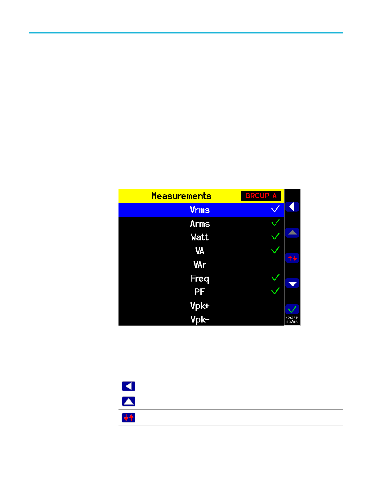
The menu system
The menu system
This section describes some of the key menus of the PA3000.
Measurement
s
Use the Measurements menu to set the order in which the measurements appear
on the screen; default measurements are: V
is on a per-g
displayed in any order, including harmonics. However, harmonic results will
always be displayed as a block (all the voltage harmonics will be displayed as a
continuous block based on the parameters set).
The following figure shows a normal Measurements screen.
roup basis. The measurements, on a group-by-group basis, can be
rms,Arms
, Watt, VA, PF, and Freq. This
Figure 22: Measurements screen
On the measurements screen you can select a measurement to display as a result
and change the order of the displayed results. The following soft keys available
with the Measurements screen:
Go to previous menu
Selection Up or top of list
Move Measurement
36 PA3000 Power Analyzer User Manual
Page 61

The menu system
Selection down or bottom of list
Select measurement to be a result on the
screen or de-select measurement
To navigate to a desired result, use the up and down arrow soft keys. The current
selection will be highlighted in blue.
If a result is selected, it has a green check mark at the right edge of the list.
The results screen shows all the selected results, in the order in which they appear
in the measurement list; the list only applies to the selected group.
NOTE. Unless the group is in Integrator mode, integration measurements cannot
be selected. These measurements are:
Hours
Watt-Hours
VA-Hours
VAr-Ho
urs
Amp-Hours
Average Watts
Average PF
Correction VAr
Fundamental VA-Hours (VAHf)
amental VAr-Hours (VArHf)
Fund
To change the order of the results, navigate to the desired result and then press
. When the key is pressed, the highlight bar changes from blue to red.
e soft keys will then change as shown below:
Th
back to the previous menu
Go
Move selected measurement up (gray if at the
top of the list already).
Cancel the move, and put the measurement
back where it was before the move was started.
Move selected measurement down (gray if at
the bottom of the list already).
Place the measurement in the selected
position. The soft keys will change back to the
standard measurement screen keys.
PA3000 Power Analyzer User Manual 37
Page 62

The menu system
The following fi
Figure 23: Example of a moved measurement
gure shows an example of a measurement being moved.
Measurement Configuration menu
Use the Measurement Configuration menu to change the way some results are
computed and displayed.
Figure 24: Measurement Configuration menu
38 PA3000 Power Analyzer User Manual
Page 63

The menu system
Harmonics Setup
The top-level m
Harmonics Setup. Use these menus to configure V, A, and W harmonics.
Distortion Setup
Minimum Hold Column
Maximum Hold Column
Sum Results Column
Sum Voltage Formulas
Sum Current Formulas
Use the Harmonics Setup to configure how quantities of harmonics are setup and
viewed as measurement results. Individual voltage, current, and watts setups
provide configurable options dependent on the application and how to view the
results. There are separate voltage, current and watts menus that allow you to
set the following items:
Sequence. Odd and even or odd harmonic only (default Odd and even)
Range. 1 to 100 (default 7)
Format. Absolute or Percentage of the fundamental (default Absolute)
enu consists of the following submenus:
Distortion setup
Display Phase Angle. On or Off (default On) (volts and amps only)
Selecting the harmonics results to display has no impact on the harmonic data
used in distortion calculations.
Please see the User Configuration section of this manual about update speed. (See
page 61, User Configuration.) The instrument is not able to calculate and display
100 harmonics on V, A, and Watts every 100 ms.
The Distortion Setup menu provides access to the voltage and current distortion
factor (df), total harmonic distortion (THD), and telephone influence factor
configurations.
Distortion factor. The distortion factor formula includes the effects of high
frequency and noise. This equation only produces a valid number if the RMS is
not less than the fundamental. If the fundamental is larger than the RMS the
display shows -----.
The equations are:
and
PA3000 Power Analyzer User Manual 39
Page 64

The menu system
The reference v
The default reference is the fundamental value.
Total Harmonic Distortion. THD is a measure of the distortion of a waveform.
Under the V and A measurement menus is the ability to set the following
parameters:
Harmonic Reference. Fundamental or RMS (default Fundamental).
Harmonic Sequence. Odd and Even or Odd Only (default is Odd and Even).
Harmonic R
calculation. If Odd Only harmonics are specified and the Range is set to an
even number, the preceding harmonic will be the last one used.
Harmonic Zero. Exclude or Include (default Exclude)
For the d
whether the actual displayed reading is turned on or off. For example, if the
number o f harmonics to be displayed is changed from 7 to 13, turning off and then
on again the display of voltage harmonics will not affect this setting.
The formula for voltage and current THD are:
alue can be either the fundamental reading or the RMS reading.
ange. 2 to 100 (default 7). This is the last harmonic used in the
istortion settings and harmonics setting, the values will be remembered
and
The Total Harmonic Distortion formula (previously called the series formula)
will produce more accurate results for harmonic noise when the THD is less
than 5%. When selecting the THD formula, it is important to set the maximum
harmonics setting to an appropriately large number to get valid results. The higher
the harmonic count the more accurate the calculation.
Telephone influence factor. The telephone influencefactor(TIF)isaTHD
measurement weighted at frequencies within the bandwidth of a normal telephone
circuit. It is a measure of how the voltage or current distortion in electrical power
circuits might interfere with adjacent telephone circuits. TIF measurements are a
requirement of standards such as ANSI C50.13 "Rotating Electrical Machinery Cylindrical-R
power generators and UPS. The harmonics included in a TIF measurement are
from1to73oddandeven.
The formula for voltage and current TIF are:
Default refe
otor Synchronous Generators" and are most often used on standby
rence = Fundamental
40 PA3000 Power Analyzer User Manual
Page 65

and
The weighting factors (kn)are:
Table 3: Weighing factors for TIF
The menu system
Minimum and Maximum
Hold Columns
Harm k
1 0.5 21 6050 41 10340
3 30 23 6370 43 10600
5
6 400 25 6680 49 9820
7
9 1320 29 7320 53 8740
11 2260 30 7570
12 2760 31 7820 59 6730
13 3360 33 8830 61 6130
15 4350 35 8830 65 4400
17 5100 36 9080 67 3700
18 5400 37 9330 71 2750
19 5630 39 9840 73 2190
n
225 24 6650 47 10210
650 27 6970 50 9670
The Minimum and Maxim
Harm k
n
Harm k
55
n
8090
um Hold Columns provide a means for adding a new
column along side the current selected results to display either the minimum or
maximum values of the selected measurements. The columns can independently
be enabled or disabled. To reset the values shown in the columns, press the
RESET/CLEAR key. Each time either the minimum or maximum hold column is
enabled, the values for both columns are reset.
Sum Results Column
The Sum Results Column provides a means to add a sum column along side
the current group of measurements. The results are displayed for multi-channel
groups. The column will appear after the last channel in the group. The maximum
column will appe
ar to the right of the sum results; the minimum column will
appear to the left of the sum results as appropriate.
Sum results are
available in all wiring configurations except 1 phase, 2 wire
(1P2W). (See page 47, Wiring.)
PA3000 Power Analyzer User Manual 41
Page 66

The menu system
Sum Voltage and Sum
Current Formulas
Modes
The PA3000 prov
and current values. The voltage methods are unrelated to the current methods. For
a list of the sum voltage and current formulas, refer to sum equations later in this
document. (See page 142, Sum equations.)
Modes are used to set up the instrument in specific way to allow certain types of
measurements. These modes provide necessary filtering and unique configuration
parameters to measure specific signals found in certain applications.
Modes are applied on a group basis. For example, in light ballast applications,
group A could be in normal mode measuring the input power and group B could
be in ball
The following modes are available:
ast mode measuring the output power.
Normal
Ballast
Standby Power
Integrator
ide a choice between two methods of summing voltage values
Normal mode
allast mode
B
PWM Mo
It is often necessary to force the instrument in to a certain way of operating when
ticular mode is selected. An example is forcing high bandwidth when Ballast
apar
mode is selected. In these cases two things will happen:
Rev
When a setting is forced, it cannot be changed by the operator while the power
alyzer is in the non-normal mode
an
Normal mode is used for most power measurements where signals are uniform and
no special measurement methods are required. Normal mode is the default mode.
Ballast mode is designed to configure the group to make measurements on the
complex ballast output modulated waveforms. In modern electronic lighting
ballasts, it is often difficult to take accurate measurements because the output
signals are high frequency waveforms that are heavily modulated by the power
frequency. Ballast mode provides a way of locking the measurement period to
the power frequency.
tor
erting back to Normal mode restores any changed settings.
42 PA3000 Power Analyzer User Manual
Page 67

The menu system
Standby P
ower mode
After selectin
which power will be transmitted. This is typically 50, 60, or 400 Hz. The setup
screen can be found under the Modes → Setup Modes → Ballast Setup.The
power analyzer uses this to adjust the measurement window to fit the specified
frequency.
The returned frequency is not the fundamental power frequency; but the ballast
switching frequency. This is also the frequency used for harmonic analysis.
When Ballast mode is selected, the frequency range is set to “>10 Hz” and the
bandwidth is set to “High” for the group. These setting are locked out in Ballast
mode and, upon the return to normal mode, the settings are restored.
Standby Power mode integrates the watts, amps, VA and PF readings over
a user-specified measurement period. This is a requirement of many standby
power standards.
Driven by consumer demand and energy efficiency legislation, there is an
ever-increasing need to measure power consumption of products while they are
in stan
One of the most widely used standards for measurement is IEC 62301. Part of
tandard requires the measurement of power over a prolonged period of time
this s
without missing any short duration power events. The Standby Power mode
provides continuous sampling of voltage and current to produce an accurate watts
measurement over the user specified period.
g Ballast mode you need to set up the fundamental frequency at
dby mode.
Integrator mode
In Standby Power mode, you must specify the integration window in seconds.
Watts, amps, PF, and VA will then be integrated over the specified period. All
other results will be updated at the normal user specified update rate.
The integration period depends on the combination of the specified window and
theupdaterateoftheinstrument. (Seepage60,Update rate.) This is because the
results will be integrated over an exact multiple of the update rate. For example, if
he update rate is 0.5 seconds (default), then the integration period will always be
t
exactly as specified. However, if an update rate of 0.4 seconds is requested, then
integration period will switch between 1.2 seconds and 0.8 seconds.
For the most accurate measurements it is recommended that the ranges are fixed
during the measurement period. (See page 50, Fixed/Auto ranging.)
Integrator mode provides measurements for determining energy consumption by
integrating measurements over a specified period or by running continuously.
Integration can be started manually, by a threshold trigger, or at a specificvalue.
In addition, for certain parameters, average values are also available.
PA3000 Power Analyzer User Manual 43
Page 68

The menu system
The required me
Measurements.) The integrator measurements are:
Hours
Watt-Hours
VA-Hours
VA r - H o u r s
Amp-Hours
Average Watts
Average P
Correction VAr
Fundamental VA-Hours (VAHf)
Fundamental VAr-Hours (VArHf)
These measurements are on a per-group basis. The measurements can only be
selected and displayed when the group is in integrator mode. If an integrator
measurement is selected and the mode is changed to a non-integrator mode, then
the measurements will show as not being selected. Changing the group mode back
egrator mode restores the selection previously used.
to int
asurements are selected in the Measurements menu. (See page 36,
F
Configuring Integrator
mode
After selecting integrator mode, and the measurements to display, there are a
number of options provided for starting and stopping the integrator under Modes
tup Mode → Integrator Setup. The following options are available:
→ Se
Start Method. Select from Manual, Clock, or Level.
Configure Clock Start. Specify a Start Time and Start Date.
Duration. Specify the integrator run duration, measured in minutes. A
duration of 0.0 will run indefinitely.
Configure Level. Select a channel, signal, threshold, or direction.
CVArs Power Factor. Specify the desired power factor to be used for the
correction VArs in the range of ±1.0 V.
44 PA3000 Power Analyzer User Manual
Page 69

The menu system
Start method. T
Manual start. This is the default method. Manual starting of integration is
triggered wit
the integrator running on all groups configured as integrator mode with a
manual start and are currently not running. The LED under the key turns on.
Clock start. Use this mode to set the time and date of when you want the
integration to start for the group. The time and date are entered in the specified
format under the Clock menu under System Configuration (See page 60.).
Once the desired time has been reached, integration will start.
If you set a time / date combination before the current time and date, then
integration will not start. Integration will only start after at le ast one screen
update has occurred before the start time.
Level start. In this start method, you have the ability to start integrating when
a certain parameter either goes above or below a user entered level. Once the
condit
You can configure the following:
Select the channel, 1 through 4.
Select a signal parameter from that channel. This can be any parameter
with the exception of integrated values and harmonic values (including
fundamentals).
he Start methods are described below.
h the INTEG RUN key on the front panel. Press this key to start
ions have been met, integration will start.
Select the threshold level to be monitored. This is the actual parameter
value in decimal. For example, for 80 mA enter 0.08; for 80 V enter 80.
Select whether the signal level should be greater than or equal to the level
or less than or equal to the level.
A trigger Channel 1-4 can be selected from any group and used as a
trigger for integration. The trigger measurement d oes not have to be in the
hannel or group that you are integrating.
c
Stopping integration. The integration of a group can be stopped manually or
after a certain period of time. If the duration for the group is set to zero, then the
integration will only stop if the INTEG RUN key is pressed. The duration is
entered in minutes as a floating point number from 0.0 to 10,000.
When you press the INTEG RUN key to manually stop the integration, integration
stops on all groups that are in integrator mode with the integrator running where
the duration is set to zero. The LED under the key turns off if there is no more
integration going on within any group.
Resetting integration values. The RESET/CLEAR key will reset the integration
values to zero for all stopped groups. It has no effect on groups that are running
integration.
PA3000 Power Analyzer User Manual 45
Page 70

The menu system
PWM Motor mode
Correction VAr
(CVArs). This parameter displays the values of VArs required to
correct the average power factor to a target power factor. The target power factor
is entered under the integrator setup screen under CVArs Power Factor.
The correction will calculate the necessary VArs to provide a phase shift to reach
a target power factor. It does not compute the total VArs. If a poor power factor is
completely due to distortion, no amount of phase lead or lag will improve it.
PWM Motor mode allows accurate measurements of PWM motors. It is designed
to overcome the difficulties associated with making measurements on the complex
waveforms found on the motor drive. High frequency sampling is combined with
digital filtering to reject the carrier frequency and extract the motor frequency
while still using pre-filtered data for power parameters.
After selecting PWM mode, select the frequency range of the motor frequency
(not the carrier frequency) under the Inputs → Frequency Source → Frequency
Range menu.
When in PWM mode, the maximum motor frequency is limited to 900 Hz, even if
a higher frequency range is selected.
The selection of the frequency range will impact the rate at which results are
returned. The update rate for all the channels is set in the System Configuration
menu. (See page 60, Update rate.) However, if the frequency range in PWM
mode is set to either 1 – 100 Hz or 0.1 – 10 Hz, then the rate at which results are
returned for t hat group is altered per the table below:
Table 4: Effects of frequency range settings i
Update rate
(seconds)
0.2 0.4 2.4 20.2
0.3 0.3 2.4 20.4
0.4 0.4 2.4 20.4
0.5 0.5 2.5 20.5
0.6 0.6 2.4 20.4
0.7 0.7 2.1 20.3
0.8 0.8 2.4 20.8
0.9 0.9 2.7 20.7
1.0 1.0 3.0 21.0
1.1 1.1 2.2 20.9
1.2 1.2 2.4 20.4
1.3 1.3 2.6 20.8
1.4 1.4 2.8 21.0
1.5 1.5 3.0 21.0
1.6 1.6 3.2 20.8
>10 Hz
<900 Hz 1 – 100 Hz 0.1 Hz – 10 Hz
nPWMmode
46 PA3000 Power Analyzer User Manual
Page 71

Table 4: Effects of frequency range settings in PWM mode (cont.)
The menu system
Inputs
Wiring
Update rate
(seconds)
1.7 1.7 3.4 20.4
1.8 1.8 3.6 21.6
1.9 1.9 3.8 20.9
2.0 2.0 4.0 22.0
>10 Hz
<900 Hz 1 – 100 Hz 0.1 Hz – 10 Hz
Results from channels not in PWM Motor mode will be returned at the specified
rate.
The Inputs menu provides configuration options for all physical signal inputs of
the pow
er analyzer. Use this menu and the submenus to configure all wiring and
group settings. For normal operation, with the exception of the shunt selection, it
is not necessary to change these settings from the default values.
For mu
ltiphase measurements, a number of channels can be assigned to a group
allowing precise frequency and phase analysis of the multiphase signals. The
frequency of the first channel in the group is used as the fundamental frequency
for all channels in the group, and all phase measurements are relative to the phase
reference (voltage by default) of the first channel in the group.
Below are figures showing how each channel would be connected for each
different wiring mode.
Figure 25: Single-phase, two-wire and DC measurements. Select 1 phase, 2 wire
mode
PA3000 Power Analyzer User Manual 47
Page 72

The menu system
Figure 26: Single-phase, three-wire. Select 1 phase, 3 wire
Figure 27: Three-phase, three-wire (2 Wattmeter method). Select 3 phase, 3 wire
Figure 28: Three phase, three wire (3 Wattmeter method). Select 3 phase, 3 wire
V3A).
(3
48 PA3000 Power Analyzer User Manual
Page 73

The menu system
Figure 29: Three-phase, three-wire (3 Wattmeter method). Select 3 phase, 4 wire
Figure 30: Three-phase, four-wire (3 Wattmeter method). Select 3 phase, 4 wire
Depending on the wiring configuration, not all groups will be available. For
le, if wiring is 1p2w for each channel, then the four channels will
examp
correspond to the four groups. If the wiring is 1p3w for group A, then Channels 1
and 2 will be in-group A. This leaves Channels 2 and 3 for a maximum of groups
B and C. Group D cannot exist in this condition.
Group A wiring takes priority, followed by groups B, C, and then D. For example,
starting from a 1p2w configuration for all groups, if group A is set to 1p3w, then
group D cannot be set to anything and therefore group C will be 1p2w only.
Group B will have the choice of 1p2w, 1p3w and 3p3w.
Line-to-Line measurements are only v alid when the signal frequency is less than
1 kHz. They are only v alid in the 1p3w, 3p3w, and 3p4w wiring configurations.
Line-to-neutral measurements are only valid in the 3p3w and the 3p3w (3V3A)
wiring configurations. The neutral current (AN) values in the math formulas is the
phase 3 line current when in the 3p3w wiring configuration.
PA3000 Power Analyzer User Manual 49
Page 74

The menu system
Ranging
Ranging sets th
e voltage or current range to a particular fixed range or to allow
ranging to automatically occur, depending on the application. For example,
current inrush testing requires the current range to be fixed; auto-ranging would
not be fast enough to capture the highest current inrush. The list of available
current ranges depends on the selected shunt.
The ranges are set on a group basis. The ranges will be as follows:
Table 5: Input ranges
Range # Volts 30 A shunt 1 A shunt Ext. shunt
Auto
4 5 V 0.5 A 0.0125 A 0.05 V
5
6 20 V 2 A 0.05 A 0.2 V
7
8 100 V 10 A 0.25 A 1 V
9 200 V 20 A 0.5 A 2 V
10 500 V 50 A 1.25 A 5 V
11 1000 V 100 A 2.5 A 10 V
12 2000 V 200 A 5 A 20 V
10 V 1 A 0.025 A 0.1 V
50 V 5 A 0.125 A 0.5 V
Fixed/Auto ranging. Auto ranging is the default selection; this is the best choice
for most measurements. Choosing a fixed range can be useful if the voltage or
current is changing continuously or has large peaks that make the power analyzer
spend excessive time changing ranges.
If you choose a fixed range, or the peak of the input signal is larger than the range,
then an over range condition will occur. This will be indicated on the screen by
l the results in the over ranged channel flashing on and off. In addition, the
al
“Vrms” and/or “Arms” will flash to indicate whether the over-range is on either
the voltage channel, the current channel, or both.
50 PA3000 Power Analyzer User Manual
Page 75

The menu system
Frequency Source
Shunts. The pow
er analyzer has three different current inputs, or shunts. They
are:
Internal 30 A. This is the default value and is used for normal current
measurement up to 30 A
(200 Apk). This selection uses the blue AHI and
rms
the gray ALO 4 mm sockets on the rear panel.
Internal 1 A. This is used for small current measurements such as those found
in standby power applications where current is less than 1 A. This selection
uses the yellow A1A and the gray ALO 4 mm sockets on the rear panel.
External. This is used for the measurement of current where an external
transducer is used and the transducer has a voltage output. The blue and black
2 mm sockets on each analog card are used for the external shunt inputs.
CAUTION. Passing an rms current of greater than 15 A when the instrument
power is off can damage the instrument. To avoid damaging the instrument, do
not apply rms currents of greater than 15 A when the instrument is off.
The Frequency Source menu provides the following selections:
Source
Phase Reference
Frequency Range
Source. Many measurements (including rms volts, amps and watts) are based
on calculations are dependent on the correct fundamental frequency being
determined by the power analyzer. The PA3000 uses proprietary techniques to
determine frequencies that eliminate problems created by noise when simple
zero-crossing techniques are used. It is therefore not normally necessary to adjust
the settings from the default of voltage.
The following source selections are available:
Volts. This is the default frequency source and is suitable for most
applications.
Amps. Amps can be selected if the voltage waveform is heavily distorted,
but the current is not. The waveforms at the output of a PWM motor drive
are an example of this.
External Frequency 1 / 2. On the rear of the power analyzer there are two
counter inputs on the Auxiliary Inputs / Outputs connector. Either of these can
be used as an external fr equency source for signals where there is too much
noise on the voltage and current waveforms. Apply a TTL compatible square
wave to the external input at the required frequency.
Phase Reference. The Phase Reference is used for harmonic analysis to create a
zero-degree reference point.
PA3000 Power Analyzer User Manual 51
Page 76

The menu system
The following s
Volts. This is the default selection; the phase is calculated with respect to the
voltage signa
Amps. Phase is calculated with respect to the current signal on the first
channel in t
External Frequency 1 / 2. Phase is calculated with respect to the external
input signa
Frequency Range.
There are
>10 Hz. This is the default selection.
1 – 100 Hz
0.1 – 10 Hz
If the fundamental frequency is greater than 50 kHz, then the range should be set
to >10 Hz. For measurements where the fundamental is below 50 kHz, the range
of >10 Hz is recommended, especially at low signal levels. The 1 – 100 Hz and
0.01 – 10 Hz ranges should only be used with slow signals; u sing these ranges
the update rates.
slows
elections are available:
lonthefirst channel in the group.
he group.
l.
three frequency ranges:
Bandwidth
Scaling
The bandwidth is set on a per-group basis. Setting the bandwidth to low applies
a 10 kHz, two-pole filter to the voltage and current channel inputs. High is the
ault selection.
def
Scaling adjusts the scaled output of transducers, such as current transformers, so
at the true measured current is displayed o n the power analyzer. The scaling
th
factor affects every measured value related to the input to which it is applied. The
maximum scale factor is 100000; the minimum is 0.00001. The default selection
is 1.0000 for all scale factors.
Volts scaling. Enter the scale factor of the transducer. For example, a 100:1
voltage transformer is used to measure 15 kV. The output of the transformer is
15000 / 100 = 150 V. Enter the scale factor 100, and the power analyzer will
display 15,000 V.
Amps scaling. Enter the scale factor of the transducer being used. For example,
the Tektronix CL1200 produces 1 A for every 1000 A flowing in the opening of
the CL. It is a 1000:1 current transformer. Enter the scale factor 1000 and the
power analyzer will display the correct current.
Scale factor = Transducer Input Current ÷ Transducer Output Current.
52 PA3000 Power Analyzer User Manual
Page 77

The menu system
Analog inputs
Graphs and waveforms
External shunt
scaling. This scaling is applied to the current measurement
channel voltage inputs. This is used for current transducers that have a voltage
output. These include Hall effect transducers as well as simple resistive shunts.
The scaling factor is expressed in Amps (read) per Volt (applied). The default
value is 1. This means that with 1 V
applied, the current channel will read 1 A
rms
rms
An example would be a clamp-on Hall effect current transducer measures up to
100 A. It has a voltage output of 10 mV per Amp, which is equivalent to 100 A /
V. Enter “100.00” and the power analyzer will display the correct system current.
The power analyzer has four analog inputs on the rear of the instrument. Each of
the four inputs can be used to measure signals from a device such as a torque or
speed sensor. Each of the four inputs has two different ranges. The ranges are
±10 V (default range) and ±1 V. Each input is sampled every millisecond and
the reported measurement is the average o f the samples over the time period
controlled by the update rate.
Analog inputs are made available to the MATH setup. They can be incorporated
into the MATH formula and displayed on the MATH screen. (See page 56, Math
results.)
.
Waveforms
Integrator parameters
The PA3000 provides different ways to display data:
Waveforms
Harmonic bar charts
Vect or d i a g r a m s
Integrator graphs
There are menu options for wavefor
ms and integrator graphing, bar charts, and
vector diagrams. (See page 12, Quick view keys.)
Use the waveform menu to select waveforms to display. For each group, you can
select any voltage, current, or watts waveform for each channel in the group to
display on the waveform graph. (See page 12, Quick view keys.)
To change groups use the left and right arrow keys at the bottom left of the display.
Use the Integrator Graph m enu to select one parameter to display on the integrator
graphing screen. The following integrator parameters are available:
Watt Hours
VA H o u r s
PA3000 Power Analyzer User Manual 53
Page 78

The menu system
VA r H o u r s
Amp Hours
Watts Average
PF Average
Volts
Amps
Watts
Fundamental VA-Hours (VAHf)
Fundamental VAr-Hours (VArHf)
Correction VArs
For each waveform selected, there is a choice on the graph menu to turn on or off
the selected parameter for each channel in the group.
Integrator graphing parameters are set on a per-group basis. To change groups use
the left and right arrow keys at the bottom left of the display.
Interfaces
RS-232 baud rate
GPIB address
Ethernet
Additional information is available for setting up the integrator. (See page 43,
Integrator mode.) Additional information is available for displaying the integrator
waveforms. (See page 17, Integrator screen.)
This menu can be used to set up the remote control interfaces of the PA3000.
9600, 19200, and 38400 (default) are available.
The PA3000 uses hardware handshaking (RT
bits and one stop bit (N,8,1).
The RS-232 baud rate is unchanged a fter a “*RST” or “:DVC” command.
Enter the GPIB address.
Default address is 6. The address is unchanged after a “*RST” or “:DVC”
command.
The PA3000 offers Ethernet communications
TCP/IP.
S / CTS) with no parity, eight data
through an Ethernet port using
The Ethernet port will make a TCP/IP connection on port 5025. Port 5025 is
designated by the Internet Assigned Numbers Authority (IANA) to be a SCPI port.
54 PA3000 Power Analyzer User Manual
Page 79

The menu system
Use the IP Selec
by selecting Set IP using DHCP,orafixed/static IP address by selecting Fix IP
Address. To view the current IP settings, press
of the menu.
To con figure the static IP address, choose Static IP Settings in the Ethernet
Setup menu.
gateway. After entering the relevant data press
For basic communication needs via TCP/IP, refer the information available from
National Instruments at (https://www.ni.com/visa).
The Ethernet mode (Static/DHCP), IP address, default gateway and subnet mask
are unchanged after a “*RST” or “:DVC” command.
Dead socket connection. Thedeadsockettermination(DST)port5030isusedto
terminate an existing Ethernet connection. A dead socket is a socket that is held
open by the instrument because it has not been properly closed. This most often
happens when the host computer is turned off or restarted without first closing the
socket. This port cannot be used for command and control functions.
Use the dead socket termination port to manually disconnect a dead session on an
open port. An existing Ethernet connection will be terminated and closed when
onnection to the dead socket termination port is made.
the c
tion Method menu, to opt for a dynamically assigned IP address,
andscrolltothebottom
This allows entry of the IP address, the subnet mask and the default
, in each menu, to apply.
PA3000 Power Analyzer User Manual 55
Page 80

The menu system
Datalog
You can configure the USB data logging interval. To configure the data logging
Math results
interval, press
The math results are displayed on a different results screen from the other results.
This improv
can be displa yed on the math results screen. They just have to be specified in a
formula. (See page 20, Math screen.)
You can set the values of up to 30 math functions, labelled FN1 through FN30.
For each function you can specify the following:
Name. User-friendly name up to 10 characters. (Default is the same as the
label, for example, FN1.) In the menus, the function label is always displayed
alongside the user’s name for the function.
Units. User friendly units such as W for watts. (Default is blank). Scaling
such as
four characte rs.
Function. The actual math formula, up to 100 characters.
Example: W = 21.49, VA = 46.45
es the ability to view math results. Normal measurement parameters
u, m, k, M will be added to the unit as appropriate. Units are up to
, go to Interfaces and select USB Host D ata Out.
Name = “PF”
ts=“PF”
Uni
Function = “CH1:W / CH1:VA”
To select this function for viewing, go to the MATH menu list showing FN1 –
FN30 and press
result value of the function; the math results display shows
.
mPF”
Example: CH1:W = 21.49, CH2:W = 53.79
Name = “EFFICIENCY”
Units=“%”
Function = “(CH1:W/CH2:W)*100”
To select this function for viewing, go to the MATH menu list showing FN1 –
FN30 and press
result value of the function; the math results display shows
39.95 mW”
.
to select the function. Next press to display the
“PF 463.27
to select the function. Next press to display the
“EFFICIENCY
56 PA3000 Power Analyzer User Manual
Page 81

The menu system
You can specify
any channel or group parameter listed below in addition to the
voltage input on each of the four analog inputs.
Valid characters are A-Z,0-9,.,x,-,+,/,(,),:,space ,
and ^
No more than 100 characters can be used
The number format is [+/-]<decimal digits>[E[+/-]exponent]
When entering a formula you can use the left and right arrow keys to move the
cursor. This allows for easy correction and changing of complex formulas.
Each math function can be either enabled or disabled. Only enabled
available for display.
The valid channel parameters are CH<1 – 4> followed by ":" and then one of the
following parameters:
Table 6: Valid channel parameters
VRMS – Volts RMS ACF – Amps Crest Factor
ARMS – Amps RMS
W – Watts VDF – Voltage Distortion Factor VF – Fundamental Volts
VA – Volt-Amps
VAR – Volt-Amps Reactive ATHD – Amps Total Harmonic Distortion WF – Fundamental Watts
FREQ – Frequency
PF – Power Factor
VPKP – Volts Peak (positive)
VPKN – Volts Peak (negative)
APKP – Amps Peak (positive)
APKN – Amps Peak (negative) TINT– Integration Time (Hours)
VDC – Volts DC
ADC – Amps DC
VRMN – Rectified Mean Volts
ARMN – Rectified Mean Amps
VCMN – Volts Corrected Rectified Mean
ACMN – Amps Corrected Rectified Mean
VCF – Volts Crest Factor CORRVARS – Correction VArs
VTHD – Voltage Total Harmonic Distortion VARHF – Fundamental VAR Hours
VTIF – Voltage Telephone Influence
Factor
ADF – Amps Distortion Factor VAF – Fundamental Apparent Power
ATIF – Amps Telephone Influence Factor
Z – Impedance PFF – Fundamental Power Factor
R – Resistance
X – Reactance
WHR – Watt Hours VLN – Line-to-Neutral Voltage
VAHR – VA Hours VHA<1–99> – Voltage Harmonic Angle
VARH VHM<1-99> – Voltage Harmonic
AHR – Amp Hours
WAV – Average Watts
PFAV – PF Average WHM<1-99> – Watts Harmonic
VAHF – Fundamental VA Hours
AF – Fundamental Amps
VARF – Fundamental Volt-Amps Reactive
VRNG – Voltage Range
ARNG – Amps Range
VLL – Line-to-Line Voltage
(1-99)
Magnitude (1-99)
AHA<1-99> – Current Harmonic Angle
(1-99)
AHM<1-99> – Current Harmonic
Magnitude (1-99)
Magnitude (1-99)
results are
The valid group parameters are G RP<A-D>: followed by one of the following
parameters:
PA3000 Power Analyzer User Manual 57
Page 82

The menu system
Table 7: Valid g
AN
roup parameters
Neutral current (or phase 3 current for 3p3w)
The valid group sum parameters are GRP<A-D> followed by ":SUM:" and then
one of the following parameters:
Table 8: Valid group sum parameters
VRMS Volts RMS ARMS Amps RMS
W Watts VA Volt-Amps
VAR Volt-Amps Reactive PF Power Factor
AHR Ampere Hours WHR Watt Hours
VAHR VA Hours VARH VAr Hours
WAV Watts Average PFAV PF average
TINT Integration Time
WF Fundamental Watts VF Fundamental Volts
AF Fundamental Amps VARF Fundamental
PFF Fundamental
Power Factor
CORRVARS Correction VArs
Volt-Amps Reactive
llow parameters are used to return the values from the analog and counter
The fo
inputs:
Table 9: Parameters for returning values from the analog and counter inputs
ANA1 Analog Input 1 ANA2 Analog Input 2
ANA3 Anal
COUNT1 Counter 1 frequency COUNT2 Counter 2 frequency
og Input 3
ANA4 Anal
og Input 4
In addition, a function can refer to another function by using “FNx” where x is the
function number. Functions will be calculated in the order of 1 through 30, so this
will have to be factored in when writing functions.
Operators available from the front panel keypad are:
+-x/()
. Shown as ^2 and will square the preceding number
. Shown as ^ and will take the preceding number to the power of the
following number
√. Shown as SQRT() and will take the square root of the number between
the brackets
58 PA3000 Power Analyzer User Manual
Page 83

The menu system
Operators that
SIN(), COS(), TAN(). These operators take an angle in degrees which is
between the br
ASIN(), ACOS(). These operators take a number between -1 and 1 which is
between the
ATAN(). Thisoperatortakesanumberthatisbetweenthebracketsand
returns an a
LN(), LOG(). This operator returns the logarithm of the number between the
brackets.
Constants that can be typed:
PI. Where π≈3.14159
NOTE. When the shift key turns on, operators such as COS(), SIN(), and TAN()
will be
and LOG() must be typed as individual letters when the shift key is turned on.
The fo
an error message is displayed. If there are no errors the calculated value will
be shown at the bottom of the screen.
entered as whole words. Operators such as A COS(), ASIN(), ATAN(), LN(),
rmula is checked for validity when OK is selected. If there is an error, then
can be typed:
ackets and return its sine, cosine or tangent.
brackets and return an angle in degrees.
ngle in degrees.
LN is log to the base e, LOG is log to the base 10.
System Configuration
Blanking
Averaging
If the math result is invalid (for example, infinity because of a divide by zero) the
display will show four dashes.
Use Blanking to zero the results below a given value. The Blanking levels are set
to 5% of the currently selected range.
When Blanking is enabled (default), all values below the threshold will show a
zero value. Disable Blanking to measure small voltages or currents.
If blanking operate s on either voltage or current then all related measurements
would be blanked including W, VA and PF.
An averaging depth of between 1 and 10 can be specified. The default value
is 10. With the update rate set to 0.5 seconds, this corresponds to values being
averaged over five seconds.
If the range is changed, the averaging is reset.
PA3000 Power Analyzer User Manual 59
Page 84

The menu system
Update rate
Autozero
Clock
The update rate
The values in the Update Rate menu list indicate the time interval (in seconds)
between every update of the results. Restrictions are placed on the number and
type of results permitted at faster update rates.
The range is 0.2 s to 2 s in 0.1 s increments, where 0.5 is the default value.
With update rates below 0.5 seconds, the number of results that can be updated
at that rate is limited.
Autozero is a method of automatically canceling any small parasitic signals, such
as DC offsets, in the measurement. Three options are available:
On. (default) The instrument runs autozero every minute.
Off. When autozero is disabled the instrument uses the last autozero values.
Run Now.
selected ranges. This takes approximately 100 m s. The state of whether
autozero is either enabled or disabled will not be changed, and there is no
feedback to indicate it has run.
Use the following options to check o r set the internal clock:
determines how often new results are available in the instrument.
The instrument runs an immediate autozero on the currently
Power saving
Set Time. Enter the time using the format shown and press to confirm.
Set Date. Enter the date using the format shown and press to con firm.
Time Format. Select 12 Hour or 24 Hour and press to confirm.
eFormat. Select the required date format and press
Dat
The instrument has the ability to reduce its own power consumption by switching
off the display.
In the Display menu you have the following options:
Always On. This is the default mode and the display will always be on.
Switch off after 10 minutes. The display turns off after 10 minutes if no key is
pressed. Pressing any key turns the display on again.
Switch off in remote mode. If the instrument receives a command through
any of the communication interfaces, the display turns off. Pressing any key
turns the display on again, but the instrument will remain in the remote mode
until the LOCAL key is pressed. PressingtheLOCALkeytoswitchthe
display on will not return the instrument to local mode.
to confirm.
60 PA3000 Power Analyzer User Manual
Page 85

The menu system
Analyzer Config
User Config
Load Defa
ult C onfiguration
Load from USB
uration
uration
The Analyzer C
key. Selecting this menu displays the complete instrument setup. Use the up and
down soft keys to scroll through the configuration.
Pressing the right arrow key changes the configurationscreentodisplay
information on the physical unit. This includes the serial number of the unit, the
firmware version, and information on the main card and analog cards, including
calibration date.
The User Configuration menu provides the means for loading changing the
current configuration.
Choosing this option by pressing sets every menu option of the PA3000 to
its factory default. The defaults are listed in previous sections of this chapter.
Load a c
onfiguration from a file on an attached USB flash drive.
onfiguration menu has the same function as the
(SETUP)
Save to USB
Configuration
Save the current configurationtoafile on an attached USB flash drive in the
\PA3000 folder.
The file name is of the format C ONFIGXY.CFG, where XY is the first available
number in the sequence of 01 to 99. For example, if a file named CONFIG01.CFG
adyexistsontheflash drive, then the new configuration will be named
alre
CONFIG02.CFG.
Save or load preset user configurations using one of eight selectable internal
rage locations.
sto
For each user configuration you can do the following:
Apply the saved configuration.
Rename the configuration. A name can have up to 16 characters.
Save a configuration. This is the complete setting of the instrument at the
time you choose this option.
NOTE. Loading a configuration that has never been saved results in an error
message. The current configuration of the unit will not be changed.
PA3000 Power Analyzer User Manual 61
Page 86

Remote operation
Remote operation
Overview
Using the remote commands the instrument can be used to perform high speed,
complex, or repetitive measurements. All PA3000 instrument communicate by
RS-232, Eth
Interfacing with RS-232 systems
ernet, or USB as standard. Optionally, a GPIB port can be added.
The RS-232
the instrument and can be used for remote control of the PA3000. A modem
cable should be used.
The RS-232 port uses 8 bits, no parity, one stop bit and hardware flow control.
See Seri
page 149, Serial port.)
See RS-
baud rate.)
port is a standard PC type 9-way male D-type located on the rear of
al Port for a detailed pin description of the RS-232 connector. (See
232 Baud Rate for details on the interface menus. (See page 54, RS-232
Interfacing with USB systems
The PA3000 supports USB control using the Test and Measurement class.
ailed pin description of the port, along with speed and connection
Adet
information is given in the Reference section of this d ocument. (See page 146,
Communication ports.)
Interfacing with Ethernet systems
The PA3000 supports Ethernet control using a 10Base-T network.
See Ethernet Port for more information on the Ethernet connection. (See
page 147, Ethernet port.)
See Ethernet Configure for information on how to set up the Ethernet addressing
information. (See page 54, Ethernet.)
62 PA3000 Power Analyzer User Manual
Page 87

Remote operation
Interfacing w
ith GPIB systems (optional)
Status reporting
Status byte
The PA3000 optionally supports control via a GPIB port. This option must be
installed by an authorized Tektronix representative.
See IEEE 488/GPIB for a detailed pin description of the GPIB connector. (See
page 148, IEEE 488 / GPIB (Optional).)
The PA3000 uses a similar status byte to IEEE 488.2. The PA3000 Status Byte
Register
non-zero state in the Standard Event Status Register (ESR) or the Display Data
Status Register (DSR) respectively.
The ESR and DSR each have enable registers, ESE and DSE respectively, set by
the user. These enable registe r s act as a mask to reflect chosen elements of the
appropriate status registers to the Status Byte Register. Setting the appropriate bit
of the enable register to 1 configures the bits to be summarized in the STB.
If a status byte is read, the DSR and ESR registers are cleared.
(STB) contains the ESB and DAS bits. These two bits indicate a
igure 31: Status byte
F
PA3000 Power Analyzer User Manual 63
Page 88

Remote operation
Status Byte Register (STB)
Display Data Status
Register (DSR)
Read by “*STB?”
.
Figure 32: Status byte register
Table 10: Status byte register bit definitions
Bit Name Description
5
0
ESB
DAS
Event status summary bit to show standard event status
Display status summary bit to show display data
Read by “:DSR?” or in summary by *STB? DAS bit. On power-up DSR is
initialized to zero. When read using the “:DSR?” command the register bits are
cleared.
Figure33: DisplayDataStatusRegister
Table11:Displaydatastatusregisterbitdefinitions
Display Data Status Enable
Register (DSE)
Bit Name Description
4
3
1NDV
0DVL
OVV Set to indicate there is a voltage range overload
OVA Set to indicate there is a current range overload
Set to indicate that new data has become available since the
last :DSR? command
Set to indicate the availability of data
Read by “:DSE?” and set by “:DSE <value>”.
Figure 34: Display Data Status Enable Register
Table12:Displaydatastatusenableregisterbitdefinitions
Bit Name Description
4
3
1 NDV Enable NDV bit
0 DVL Enable DVL bit
OVV Enable OVV bit
OVA Enable OVA bit
64 PA3000 Power Analyzer User Manual
Page 89

Remote operation
Standard Event Status
Register (ESR)
Standard Event Status
Enable Register (ESE)
Read by “*ESR?”
or in summary by the ESB bit in STB.
Figure 35: Standard Event Status Register
Table 13: St
Bit Name Descriptio
5
4EXE
2
Read by “
andard event status register bit definitions
n
CME Command err
Command ex
QYE Query err
or; command not recognized
ecution error
or
*ESE?” and set by “*ESE <value>”.
Figure 36: Standard Event Status Enable Register
14: Standard event status enable register bit definitions
Table
Bit Name Descr
5
4 EXE Enable EXE bit
2
CME Enabl
QYE Enable QYE bit
iption
eCMEbit
PA3000 Power Analyzer User Manual 65
Page 90

Remote operation
Command listi
ng
The following conventions are used for command syntax:
Square brackets indicate optional parameters or keywords [ ].
Anglebracketsindicatevaluestobespecified < >.
Commands and responses are sent as ASCII strings terminated with a line feed.
The PA3000 is not case sensitive and white space characters are ignored except
where required between command and parameter.
Multiple commands cannot be sent in a single string where a semicolon (;) is used
at the end of each command.
For all commands where a parameter is supplied, a space is required between the
end of the command and the first parameter. For example,
work. However,
The list of commands is split into relevant sections. In general each section
corresponds to a menu option from the Main Menu.
:SYST:CTYPE?1 causes a time out error.
:SYST:CTYPE? 1 will
66 PA3000 Power Analyzer User Manual
Page 91

IEEE 488.2 standard commands and status commands
Remote operation
*IDN?
*CLS
*ESE
Unit identity
Syntax
Returns
Description
*IDN?
Tektronix, PA3000, serial number, firmware version
The serial number is the serial number of the main chassis. The firmware
version is the version of the firmware suite, which i ncludes all processors.
Clear event status
Syntax
Description This command clears all event registers and queues.
*CLS
Set standard event status enable register
Syntax
Default
Description
*ESE <flags>
Where flag
0
This com
are summarized by the ESB bit in the Status Byte. The Standared Event
Status Enable Register uses the same bit definitions as the Standard
Event S
s is the value for enable register as a decimal 0 – 255
mand sets the bits in the Standard Event Status Register that
tatus Register.
*ESE?
*ESR?
Read standard event status enable register
Syntax
Returns 0 – 255
Description
*ESE?
This command returns the value in the Standard Event Status Enable
Register.
Read standard event status register
Syntax
Returns 0 – 255
cription
Des
*ESR?
This command returns the value in the Standard Event Status Register.
The register is cleared once it has been read.
PA3000 Power Analyzer User Manual 67
Page 92

Remote operation
*RST
*STB?
:DSE
Reset device
Syntax
Description
*RST
This command resets the unit configuration to default values (performs the
same action as Load Default Configuration menu option on the front panel).
Allow at least three seconds after sending the *RST command before sending
further commands to allow all defaults to be processed and set.
Read status byte
Syntax
Returns 0 – 255
Description This command returns the value in the status byte.
*STB?
SetDataStatusEnableRegister
Syntax
Default
Description
:DSE <flags>
Where flags is the valu
255
This command sets t
summarized by the DAS bit in the Status Byte.
e for enable register as a decimal 0 – 255
he bits in the Data Status Enable register that are
:DSE?
:DSR?
:DVC
Read Data Status Enable Register
DSE?
Syntax
Returns 0 – 255
Description
:
This command returns the value in the Data Status Enable register.
Read Data St atus Register
Syntax
Returns 0 – 255
Description
:DSR?
This command returns the value in the Data Status register. T he Data
Status Register is cleared once it has been read.
Device clear
Syntax
Description
Allow at least three seconds after sending the *RST com
:DVC
This command has the same affect as
(loading the default user configuration).
*RST or :CFG:USER:LOAD 0
mand before sending
further commands to allow all defaults to be processed and set.
68 PA3000 Power Analyzer User Manual
Page 93

Remote operation
Channel and gr
:INST:NSEL
:INST: NSEL?
oup commands
The following commands are used to select the active group or channel. They are
similar in concept to pressing the left and right arrow keys to change the group or
channel whil
Set active group
Syntax
Description
Read active group
Syntax
Returns <group number>
tion
Descrip
e displaying a menu screen.
:INST:NSEL <group number>
Where <group number> is an integer between 1 and 4, depending on the
number of groups available in the power analyzer
This command sets the specified group as the active group for command
and actions that might follow. Not affected by reset.
:INST:NSEL?
This command returns the number of the group selected (between 1 and 4
depending on wiring configuration).
:INST:NSELC
:INST:NSELC?
Select active channel
Syntax
Description
:INST:NSELC <channel number>
Where <channel number> is an integer between 1 and 4, depending on the
number of channels installed in the power analyzer. Not affected by reset.
This command sets the number of the channel selected (between 1 and 4)
depending on number of channels installed in the power analyzer.
Return active channel
Syntax
Returns <channel number>
Description
:INST:NSELC?
This command returns the number of the channel selected (between 1 and
4) depending on number of channels installed.
PA3000 Power Analyzer User Manual 69
Page 94

Remote operation
Unit informat
:CAL:DATE?
:SYST:CTYPE?
ion commands
The Unit Information commands are commands that are used to return information
on the unit beyond the information returned by the *IDN? command.
Calibration date
Syntax
Returns
Description
Card type
Syntax
Returns Tektronix, <card type>, <serial number>, <hardware revision>
Description This command returns the card type, serial number and hardware revision
:CAL:DATE? <channel number>, <date type>
Where <chan
Appropria
This comma
card. <date type> can be either 1 for date verified or 2 for date adjusted.
:SYST:CTYPE? <channel number>
Where <channel number> is 0 through 4
<card type> is either CPU for the main card, or ANALOG for a channel
card.
<serial number> is a 12 character string.
<hardware revision> is up to four characters.
for the designated channel. Channel 0 is the main CP U card.
nel number> is 1 through 4 and <date type> is 1 through 2
te calibration date in the format dd-mm-yyyy
nd returns the calibration date from the designated analog
Measurement selection and reading commands
commands are related to selecting the required measurements and returning
These
the results.
70 PA3000 Power Analyzer User Manual
Page 95

Remote operation
:SEL
Select results
Syntax
:SEL:ALL
:SEL:ALL:GRP<group>
:SEL:CLR
:SEL:CLR:GRP
:SEL:<measurement>
Where <group> is a group number 1 through 4.
Where <measu
VLT – Volts rms
AMP – Amps rms
WAT – Watts
VAS – VA
VAR – VAr
FRQ – Frequ
PWF – Power factor
VPK+ – Volts peak (positive)
VPK- – Volt
APK+ – Amps peak (positive)
APK- – Amps peak (negative)
VDC – Volt
ADC – Amps DC
VRMN – Volts rectified mean
ARMN – Amp
ACMN – Amps corrected rectified mean
VCMN – Volts corrected rectified mean
VCF – Vol
ACF – Amps crest factor
VTHD – Volts Total Harmonic Distortion
VDF – Vo
VTIF – Volts Telephone Influence Factor
ATHD – Amps Total Harmonic Distortion
ADF – Am
ATIF – Amps Telephone Influence Factor
IMP – Impedance
RES – R
REA – Reactance
HR – Integrator time
WHR – W
VAH – VA Hours
VRH – VAr Hours
AHR –
WAV – Average Watts
PFAV – Average Power Factor
CVAR
VAHF – Fundamental VA-hours
VARHF – Fundamental VAr-hours
VF –
AF – Fundamental Amps rms
WF – Fundamental Watts
<group>
rement> is:
ency
s peak (negative)
sDC
srectified mean
ts crest factor
lts Distortion Factor
ps Distortion Factor
esistance
1
att Hours
Amp Hours
– Correction VArs
1
1
1
1
1
1
Fundamental Volts rms
1
PA3000 Power Analyzer User Manual 71
Page 96

Remote operation
Select results (cont.)
VAF – Fundamental VA
VARF – Fundamental VAr
PFF – Fundamental Power Factor
VRNG – Voltage range
ARNG – Current range
VLL – Line-to-line voltage
VLN – Line-to-neutral voltage
VHM – Volts harmonics
AHM – Amps harmonics
WHM – Watts harmonics
Description
1
These results are only available for displaying / returning when the group is in integrator mode.
:SEL determines which results are displayed on the screen, also the results
returned by the :FRD? command. To see the currently selected command, use
the :FRF? command.
:SEL:ALL selects all results. Adding the secondary command of :GRP allow only
those results within the speci fied group to be selected.
:SEL:CLR clears all the results selected for all groups. Adding the secondary
command of :GRP allows only those results within the specified group to be
cleared.
To add results to a group the :INST:NSEL <group> command must be used first.
If it is not, then the last selected group will be affected (or group 1 if no group
has previously been selected).
72 PA3000 Power Analyzer User Manual
Page 97

Remote operation
:FRF?
Read selected r
Syntax
Description
Returns
esults
:FRF?
:FRF:GRP<group>?
:FRF:CH<channel>?
Where <group
Where <channel> is a channel number 1 through 4
:FRF? and :FRF:GRP? commands return a list of the displayed results.
The actual result is not returned.
<group>, <number of measurements selected>, <number of results
returned>
measurements selected>, ...
<number of measurements selected> is the number of measurements
selected u
<number of results returned> equals the number of rows on the display
used. When harmonics are selected, the number of results returned will
exceed th
<measurement 1>, <measurement 2>, ... are the names of the selected
measurements. The returned data will be the same as the label on the
results
returned. Each returned value will be separated by a comma.
:FRF? will return the selections for all groups.
:FRF:CH
This is useful for ease of measurements. The data returned for this
command will be the same as “:FRF:GRP?”, except the channel number
so be included. For example:
will al
<group>, <channel>, <number of measurements selected>, <number of
results returned>, <measurement 1>, <measurement 2>, ..., <group>,
<chan
> is a group number 1 through 4
, <measurement 1>, <measurement 2>, ..., <group>, <number of
sing either the front panel or the SEL command.
e number of measurements selected.
display. For harmonics: “Vharm”, “Aharm”, and “Wharm” will be
<channel>? will return the list of results for a particular channel.
nel>, <number of measurements selected>, ...
:MOVE
Move results
Syntax
Description
:MOVE:<measurement> <new position>
Where <measurement> is the list of measurements defined under the
:SEL command. (See page 71, :SEL.)
<new position> is the position in the list of results on the screen and is
in the r ange 1 through 51.
The move command is used to change the order of results on both the
screen in the returned results using :FRD?. :FRF? can be used to confirm
the order of results.
PA3000 Power Analyzer User Manual 73
Page 98

Remote operation
:FRD?
Read foregroun
Syntax
Description
Returns
ddata
:FRD?
:FRD:CH<ch>?
:FRD:GRP<group>?
Where <ch> is a
Where <group> is a group number 1 through 4
The commands returns results from the power analyzer. The results are
returned in the order in which they are displayed on the screen. Each
result is a fl
The sequence is determined by order in which results are displayed on the
front panel. The sequence can be configured either by changing the order
using the f
Results w ill be returned column by column starting from the left of the
display. This means that if the user has selected Sum results or Max and
Min result
For :FRD:
returned. The order will be <min>, <ch>, <max>.
For :FRD:GRP<group>?, if Min, Max, or Sum results are selected, these
will be re
<max>, ..., <sum min>, <sum>, <sum max>.
For :FRD?, each group will be returned starting with group A. The order
sults with the group will be the same as the :FRD:GRP <group>?
of the re
command.
channel number 1 through 4
oating point number separated by a comma.
ront panel of the instrument, or by using the :MOVE command.
s to be displayed, then these results will also be returned.
CH<ch>?, if Min or M ax results are selected, these will be
turned. The order will be <min>, <ch>, <max>, <min>, <ch>,
Measur
:HMX:
ement configuration commands
Measurement configuration commands correspond to the Measurement
Configuration menu. (See page 38, Measurement Configuration menu.)
VLT/AMP/WAT
Commands for configuring the display of harmonics.
Harmonics configuration
Syntax
Description
:HMX:VLT:SEQ <value>
:HMX:AMP:SEQ <value>
:HMX:WAT:SEQ <value>
Where <value> equals 0 for odd and even and 1 for odd only
If harmonics measurements are selected with the :SEL command (See
page 71.), the power analyzer can display all harmonics, or just the odd
number harmonics from the first harmonic up to the number specified.
This command works on a group. Use the :INST:NSEL command first
to select the active group.
74 PA3000 Power Analyzer User Manual
Page 99

Harmonics configuration (cont.)
Remote operation
Syntax
Descripti
Syntax
Description
on
:HMX:VLT:RN
:HMX:AMP:RNG <value>
:HMX:WAT:RNG <value>
Where <valu
1 to 100
If harmonics measurements are selected with the :SEL command (See
page 71.), the power analyzer will display all the harmonics up to the
number sp
to only odd numbered harmonics using the harmonic sequence command.
This command works on a group. Use the :INST:NSEL command first
to select
:HMX:VLT:FOR <value>
:HMX:AMP:FOR <value>
:HMX:WAT:FOR <value>
Where <value> is 0 for absolute values or 1 for percentage values
If harmonics measurements are selected with the :SEL command (See
page 71.), the power analyzer can display all harmonics (except the first) as
an absolute value or as a percentage of the fundamental (first) harmonic.
This command works on a group. Use the :INST:NSEL command first
to select the active group.
G <value>
e> is the maximum harmonic to be display in the range of
ecified by <value>. The displayed harmonics can be restricted
the active group.
:VLT/AMP:DF
:HMX
Commands for setting up the distortion factor measurements.
Distortion factor setup
Syntax
Description
:HMX:VLT:DF:REF <value>
:HMX:AMP:DF:REF <value>
Where <value> is 0 for fundamental or 1 for rms
For distortion factor readings (also known as the difference formula),
the reference on the denominator of the equation can be either the rms
reading or the fundamental harmonic reading.
This command works on a group. Use the :INST:NSEL command first
to select the active group.
PA3000 Power Analyzer User Manual 75
Page 100

Remote operation
:HMX:VLT/AMP
:PHA
:HMX:VLT/AMP:THD
Display phase a
Syntax
Description
Syntax
Returns 0 or 1
ngle
:HMX:AMP:PHA <value>
:HMX:VLT:PHA <value>
Where <value> is 0 for on or 1 for off
This command turns the display of the voltage or current phase angle
on or off (default On).
:HMX:AMP:PHA?
:HMX:VLT:PHA?
Commands for setting up the total harmonic distortion measurements.
Total har
Syntax
Description
Syntax
Descr
Syntax
Description
monic distortion setup
:HMX:VLT:THD:REF <value>
:HMX:AMP:THD:REF <value>
Where <value> is 0 for fundamental or 1 for rms
For total harmonic distortion (THD) readings (also known as the series
formula), the reference on the denominator of the equation can be either
the rms reading or the fundamental harmonic reading.
This command works on a group. Use the :INST:NSEL command first
to select the active group.
:HMX:VLT:THD:SEQ <value>
:HMX:
Where <value> is 0 for odd and even or 1 for odd only
iption
For total harmonic distortion (THD) readings, the harmonics used in the
measurement can include all harmonics up to the specified number or only
dd harmonics.
the o
This command works on a group. Use the :INST:NSEL command first
to select the active group.
:HMX:VLT:THD:RNG <value>
:HMX:AMP:THD:RNG <value>
Where <value> is the maximum harmonic to display in the range of 2 to
100.
For total harmonic distortion (THD) readings, <value> specifies the
maximum harmonic number used in the formula.
This command works on a group. Use the :INST:NSEL command first
to select the active group.
AMP:THD:SEQ <value>
76 PA3000 Power Analyzer User Manual
 Loading...