

Page 1

PA1000
xx
ZZZ
Power Analyzer
User Manual
*P077091201*
077-0912-01
Page 2

Page 3

xx
PA1000
ZZZ
Power Analyzer
User Manual
Firmware Version 1.003.012 and above
www.tektronix.com
077-0912-01
Page 4

Copyright © Tektronix. All rights reserved. Licensed software products are owned by Tektronix or its subsidiaries
or suppliers, and are protected by national copyright laws and international treaty provisions.
Tektronix products are covered by U.S. and foreign patents, issued and pending. Information in this publication
supersedes that in all previously published material. Specifications and price change privileges r ese rved.
TEKTRONIX and TEK are registered trademarks of Tektronix, Inc.
Contacting Tektronix
Tektronix, Inc.
14150 SW Karl Braun Drive
P.O . Bo x 5 00
Beaverto
USA
For product information, sales, service, and technic al support:
n, OR 97077
In North America, call 1-800-833-9200.
Worldwide, visit www.tektronix.com to find contacts in your area.
Page 5

Warranty
Tektronix warrants that this product will be free from defects in materials and workmanship for a period of three
(3) years from the date of shipment. If any such product proves defective during this warranty period, Tektronix, at
its option, either will repair the defective product without charge for parts and labor, or will provide a replacement
in exchange for the defective product. Parts , modules and replacement products used by Tektronix for warranty
work may be n
the property of Tektronix.
ew or reconditioned to like new performance. All replaced parts, m odules and products become
In order to o
the warranty period and make suitable arrangements for the performance of service. Customer shall be responsible
for packaging and shipping the defective product to the service center designated by Tektronix, w ith shipping
charges prepaid. Tektronix shall pay for the return of the product to Customer if the shipment is to a location within
the country in which the Tektronix service center is located. Customer shall be responsible for paying all shipping
charges, duties, taxes, and any other charges for products returned to any other locations.
This warranty shall not apply to any defect, failure or damage caused by improper use or improper or inadequate
maintenance and care. Tektronix shall not be obligated to furnish service under this warranty a) to repair damage
result
b) to repair damage resulting from im proper use or connection to incompatible equipment; c) to repair any damage
or malfunction caused by the use of non-Tektronix supplies; or d) to service a product that has been modified or
integrated with other products when the effect of such modification or integration increases the time or difficulty
of servicing the product.
THIS WARRANTY IS GIVEN BY TEKTRONIX WITH RESPECT TO THE P RO DUC T IN LIEU OF ANY
OTHER WARRANTIES, EXPRESS OR IMPLIED. TEKTRONIX AND ITS VENDORS DISCLAIM ANY
IMPLIED WARRANTIES OF MERCHANTABILITY OR FITNESS FOR A PARTICULAR PURPOSE.
TRONIX' RESPONSIB ILITY TO REPAIR OR REPLACE DEFECTIVE PRODUCTS IS THE SOLE
TEK
AND EXCLUSIVE REMEDY PROVIDED TO THE CUSTOMER FOR BREACH OF THIS WARRANTY.
TEKTRONIX AND ITS VENDORS WILL N OT BE LIABLE FOR ANY INDIRECT, SPECIAL, INCIDENTAL,
OR CONSEQUENTIAL DAMAGES IRRESPECTIVE OF WHETHER TEKTRONIX OR THE VENDOR HAS
ADVAN CE NOTICE OF THE POSSIBILITY OF SUCH DAMAGES.
[W4 – 15AUG04]
btain service under this warranty, Customer must notify Tektronix of the defect before the expiration of
ing from attempts by personnel other than Tektronix representatives to install, repair or service the product;
Page 6

Page 7

Table of Contents
Important safety information....... .................................. ................................ ............. v
General safety summary ...................................................................................... v
Service safety summary.............. .................................. ................................ ..... vii
Terms in this manual ............. ................................ .................................. ......... viii
Symbols and terms on the product......................................................................... viii
Compliance information ........................................................................................... x
EMC compliance . .................................. .................................. ......................... x
Safety compliance ............................................................................................ xi
Environmental considerations .............................................................................. xiv
Preface .............................................................................................................. xv
Introduction ......................................................................................................... 1
Basic features................................................................................................... 1
Standard accessories........................................................................................... 2
Optional accessories.............. .................................. ................................ ........... 2
Service options .......................... .................................. .................................. ... 3
Getting started. . ... ... . ... ... . ... ... . ... . . ... ... . ... . . ... ... .. ... ... . ... . . ... ... . ... ... . ... ... . ... .. ... ... . ... ... . ... 4
Before you begin - safety .. .................................. .................................. ............... 4
Power on........................... ................................ .................................. ........... 6
Controls and connectors....................................................................................... 7
Connecting to the product under test ........................................................................ 9
Default measurements........................................................................................ 12
Navigating the menu system................................................................................. 13
Data logging................................................................................................... 14
Unit configuration ............................................................................................ 16
The menu system .................................................................................................. 17
Navigation......... .................................. ................................ .......................... 17
Modes .......................................................................................................... 18
Inputs................. .................................. .................................. ...................... 21
Graphs.. .................................. ................................ .................................. .... 23
Interfaces ...................................................................................................... 24
System configuration... .................................. ................................ .................... 24
User configuration ............................................................................................ 26
View .......................... .................................. .................................. .............. 26
Connecting signals .. .................................. .................................. .......................... 27
Input overview .............. ................................ .................................. ................ 27
To connect a simple current transformer ........... ................................ ........................ 28
To connect an external resistive shunt .................................. .................................. .. 29
To connect a transducer with a voltage output............................................................. 30
To connect a voltage transformer / transducer............................................................. 31
PA1000 Power Analyzer i
Page 8

Table of Contents
Remote operati
Overview .......... ................................ .................................. .......................... 33
Interfacing with USB systems............................................................................... 33
Interfacing with Ethernet systems..................... .................................. .................... 33
Interfacing with GPIB systems.............................................................................. 34
Status reporting ....... .................................. ................................ ...................... 34
Command listing.............................................................................................. 36
IEEE 488.2 standard commands and status commands .................................................. 37
Unit information commands....................... ................................ .......................... 39
Measurement selection and reading commands ........................... ................................ 40
Measurement configuration commands .................................................................... 41
Mode setup commands............... ................................ .................................. ...... 43
Input setup commands ....................................................................................... 45
Graph and waveform commands.......................... .................................. ................ 48
Interface commands ........ .................................. .................................. .............. 49
System configuration commands............................................................................ 51
User configuration commands......................................... .................................. .... 53
View commands ........................ .................................. .................................. .. 53
Sending and receiving commands .......................................................................... 54
Communications examples ........ .................................. .................................. ...... 55
Software ............ .................................. ................................ .............................. 57
PWRVIEW PC software .................................................................................... 57
PA1000 firmware update utility . . ... . . ... ... . ... . . ... ... . ... . . ... ... . ... . . ... ... . ... .. ... ... . ... . . ... ... . ... 58
Applications examples ................ ................................ .................................. .......... 60
IEC 62301 compliance testing and low-power standby measurements ................................ 60
IEC 61000-3-2 pre-compliance current harmonics testing............................. .................. 63
Specifications .................... ................................ .................................. ................ 72
Measurement channel ...................... .................................. ................................ 72
Power input.. .................................. .................................. .............................. 72
Mechanical and environmental.............................................................................. 73
Communication ports......................................................................................... 74
Measured parameters......................................................................................... 76
Power polarity................................................................................................. 77
Digital filter.................................................................................................... 78
Measurement accuracy. .................................. .................................. .................. 78
Appendix A: Input fuse replacement ............................................................................ 81
Check the fuse................................................................................................. 82
Select the proper fuse......................... .................................. .............................. 82
Fuse replacement procedure ................................................................................. 82
Index
on ................................ .................................. ................................ 33
ii PA1000 Power Analyzer
Page 9

List of Figures
Figure 1: PA1000 Power Analyzer .............. ................................ ................................. 1
Figure 2: Initial power-on d isplay . . ... . ... . . ... . . ... .. ... . . ... .. ... . . ... . . ... . . ... .. ... . . ... .. ... . . ... .. ... ... . .. 6
Figure 3: PA1000 front panel ..................................................................................... 7
Figure 4: PA
Figure 5: Typical PA1000 input connections.................................................................... 9
Figure 6: Breakout box ........................................................................................... 10
Figure 7: Typical breakout box connections.......................... ................................ .......... 11
Figure 8: Default measurement display......................................................................... 12
Figure 9: Display soft keys....................................................................................... 12
Figure 1
Figure 11: PA1000 logged data .................................................................................. 15
Figure 12: Current transformer connections.................... .................................. .............. 28
Figure 13: External resistive shunt connections ............................................................... 29
Figure 14: Transducer with voltage output connections ........................ .............................. 31
Figure 15: Voltage transformer / transducer connections ..................................................... 32
re 16: Communication ports .............. ................................ .................................. 33
Figu
Figure 17: PWRVIEW application .............................................................................. 58
Figure 18: Laptop charger full-compliance standby power test with PWRVIEW software. ... . ... . . ... .. 61
Figure 19: PA1000 measuring 5 mW in front-panel standby mode.................. ........................ 62
Figure 20: Standby power measurement connections ......................................................... 62
Figure 21: IEC 61000-3-2 pre-compliance test running on PWRVIEW software ............. ............ 65
gure 22: Connection diagram for IEC 61000-3-2 pre-compliance current harmonics test.. ... . ... . ... . 66
Fi
Figure 23: Connecting a power analyzer for the first time using the PWRVIEW software ............... 67
Figure 24: Pre-compliance harmonics test setup......................................... ...................... 67
Figure 25: Test environment and other important information setup ............ ............................ 68
Figure 26: Select load class based on IEC standard ........................................................... 68
Figure 27: IEC 61000-3-2 pre-compliance test ................................................................ 69
Figure 28: Table view for IEC 61000-3-2 pre-compliance test .............................................. 69
Figure 29: Results summary for IEC 61000-3-2 pre-compliance test ....................... ................ 70
Figure 30: Harmonics results with scroll bars for time and amplitude ... . . ... . . ... ... . ... .. ... ... . ... .. ... . 70
Figure 31: PDF report for IEC61000-3-2 pre-compliance test........... .................................. .. 71
Figure 32: Input fuse rating ...................................................................................... 81
Figure 33: Input fuse location ....... .................................. ................................ .......... 82
1000 rear panel ...................................................................................... 8
0: Menu keys............................................................................................. 13
PA1000 Power Analyzer iii
Page 10

Table of Contents
List of Tables
Table 1: Standard accessories .............. .................................. .................................. ... 2
Table 2: Opt
Table 3: Service options .......... .................................. ................................ ............... 3
Table 4: Available measurements per mode........ .................................. .......................... 19
Table 5: Phase measurements.... ................................ .................................. .............. 76
Table 6: Power polarity ........................................................................................... 77
ional accessories .......... .................................. .................................. ....... 2
iv PA1000 Power Analyzer
Page 11

Important safety information
This manual contains information and warnings that must be followed by the user
for safe operation and to keep the product in a safe condition.
To safely perform service on this product, additional information is provided at
the end of this section. (See page vii, Service safety summary.)
General safety summary
Use the product only as specifi ed. Review the following safety precautions to
avoid inj
Carefully read all instructions. Retain these instructions for future reference.
ury and prevent damage to this product or any products connected to it.
Comply wi
For correct and safe operation of the product, it is essential that you follow
general
in this m anual.
The pro
Only qualified personnel who are aware of the hazards involved should remove
the co
Before use, always check the product with a known source to be sure it is
oper
This product is not intended for detection of hazardous voltages.
Use personal protective equipment to prevent shock and arc blast injury where
hazardous live conductors are exposed.
While using this product, you may need to access other parts of a larger system.
Read the safety sections of the other component manuals for warnings and
autions related to operating the system.
c
When incorporating this equipment into a system, the safety of that system is the
esponsibility of the assembler of the system.
r
th local and national safety codes.
ly accepted safety procedures in addition to the safety precautions specified
duct is designed to be used by trained personnel only.
ver for repair, maintenance, or adjustment.
ating corr ectly.
To avoid fire or personal
injury
PA1000 Power Analyzer v
Use proper power cord. Use only the power cord specified for this product and
certified for the country of use.
Do not use the provided power cord for other products.
Ground the product. This product is grounded through the grounding conductor
of the power cord. To avoid electric shock, the grounding conductor must be
connected to earth ground. Before making connections to the input or output
terminals of the product, make sure that the product is properly grounded.
Page 12

Important safety information
Power disconne
source. See instructions for the location. Do not position the equipment so that it
is difficult to disconnect the power switch; it must remain accessible to the user at
all times to allow for quick disconnection if needed.
Connect and disconnect properly. Do not connect or disconnect probes or test
leads while they are connected to a voltage source.
Use only insulated voltage probes, test leads, and adapters supplied with the
product, or indicated by Tektronix to be suitable for the product.
Observe all terminal ratings. To avoid fire or shock hazard, observe all ratings
and markings on the product. Consult the product manual for further ratings
information before m aking connections to the product. Do not exceed the
Measurement Category (CAT) rating and voltage or current rating of the lowest
rated individual com ponent of a product, probe, o r accessory. Use caution when
using 1:1 test leads because the probe tip voltage is directly transmitted to the
product.
Do not apply a potential to any terminal, including the common terminal, that
exceeds the maximum rating of that terminal.
Do not float the common terminal above the rated voltage for that terminal.
Do not operate without covers. Do not operate this product with covers or panels
removed, or with the case open. Hazardous voltage exposure is possible.
ct. The power switch disconnects the product from the power
Avoid exposed circuitry. Do not touch exposed connections and components
when power is p resent.
Do not operate with suspected failures. If you suspect that there is damage to this
product, have it inspected by qualified service personnel.
Disable the product if it is damaged. Do not use the product if it is damaged
or operates incorrectly. If in doubt about safety of the product, turn it off and
disconnect the power cord. Clearly mark the product to prevent its further
operation.
Before use, inspect voltage probes, test leads, and ac cessories for mechanical
damage and replace when damaged. Do not use probes or test leads if they are
damaged, if there is exposed metal, or if a wear indicator shows.
Examine the exterior of the product before you use it. Look for cracks or missing
pieces.
Use only specified replacement parts.
Use proper fuse. Useonlythefusetypeandratingspecified for this product.
Do not operate in wet/damp conditions. Be aware that condensation may occur if
a unit is moved from a cold to a warm environment.
vi PA1000 Power Analyzer
Page 13

Important safety information
Probes and test leads
Do not operate i
Keep product surfaces clean and dry. Remove the input signals before you clean
the product.
Provide proper ventilation. Refer to the installation instructions in the manual for
details on installing the product so it has proper ventilation.
Slots and openings are provided for ventilation and should never be covered or
otherwise obstructed. Do not push objects into any of the openings.
Provide a safe working environment. Always place the product in a location
convenient for viewing the display and indicators.
Avoid improper or prolonged use of keyboards, pointers, and button pads.
Improper or prolonged keyboard or pointer use may result in s erious injury.
Be sure your work area meets applicable ergonomic standards. Consult with an
ergonomics professional to avoid stress injuries.
Before connecting probes or test leads, connect the power cord from the power
connector to a properly grounded power outlet.
Remove all probes, test leads and accessories that are not in use.
n an explosive atmosphere.
Use only correct Measurement Category (CAT), voltage, temperature, altitude,
and amperage rated probes, test leads, and adapters for any measurement.
Connect and disconnect properly. De-energize the circuit under test before
connecting or disconnecting the current probe.
Connect the probe reference lead to earth ground only.
Do not connect a current probe to a ny wire that carries voltages above the current
probe voltage rating.
Inspect the probe and accessories. Before each use, inspect probe and accessories
for damage (cuts, tears, or defects in the probe body, acc ess ories, or cable jacket).
Do not use if damaged.
Servicesafetysummary
The Service safety summary section contains additional information required to
safely perform service on t
service procedures. Read this Service safety summary and the General safety
summary before performing any service procedures.
To avoid electric shock. Do not touch ex posed connections.
he product. Only qualified personnel should perform
PA1000 Power Analyzer vii
Page 14
Important safety information
Termsinthismanual
Do not service a
product unless another person capable of rendering first aid and resuscitation is
present.
Disconnect power. To avoid electric shock, switch off the product power and
disconnect the power cord from the mains power before removing any covers or
panels, or o
Use care when servicing with power on. Dangerous voltages or currents may exist
in this product. Disconnect power, remove battery (if applicable), and disconnect
test leads before removing protective panels, soldering, or replacing components.
Verify sa
strength after performing a repair.
These terms may appear in this manual:
WARNING. Warning statements identify conditions or practices that could result
in injury or loss of life.
fety after repair. Always recheck ground continuity and mains dielectric
lone. Do not perform internal service or adjustm ents of this
pening the case for servicing.
CAUTION. Caution statements identify conditions or practices that could result in
damage to this product or other property.
Symbols and terms on the product
These terms may a ppear on the product:
DANGER indicates an injury hazard immediately accessible as you read
the marking.
WARNING indicates an injury hazard not immediately accessible as you
read the marking.
CAUTION indicates a hazard to property including the product.
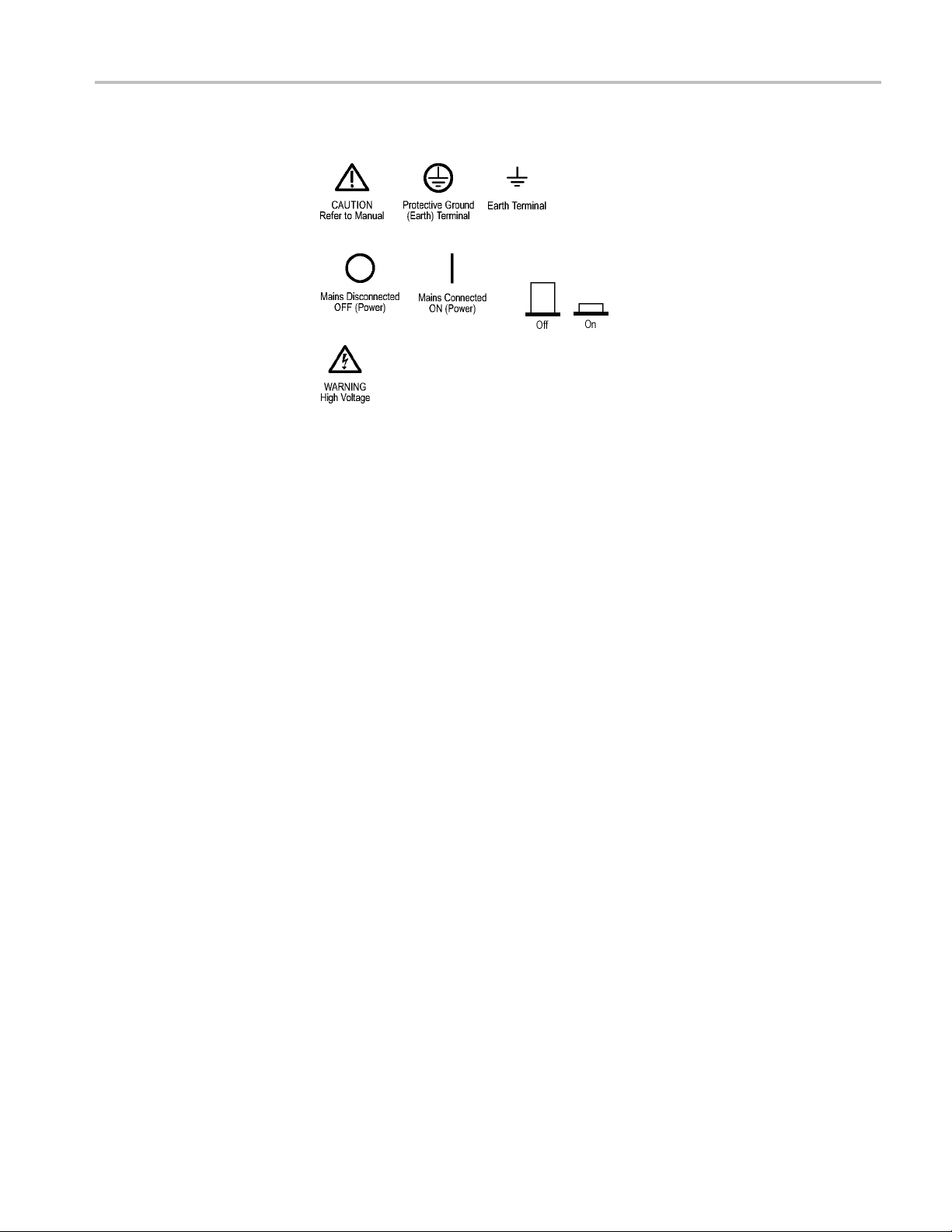
When this symbol is marked on the product, be sure to consult the manual
to find out the nature of the potential hazards and any actions which have to
betakentoavoidthem. (Thissymbolmayalsobeusedtorefertheuserto
ratings in the manual.)
viii PA1000 Power Analyzer
Page 15
Important safety information
The following s
ymbol(s) may appear on the product:
PA1000 Power Analyzer ix
Page 16

Compliance information
Compliance in
EMC compliance
EC Declaration of
conformity – EMC
formation
This section
environmental standards with which the instrument complies.
Meets intent of Directive 2004/108/EC for Electromagnetic Compatibility.
Compliance was demonstrated to the following specifications as listed in the
Official Journal of the European Communities:
EN 61326-1:2006, EN 61326-2-1:2006. EMC requirements for electrical equipment
for meas
CISPR 11:2003. Radiated and conducted emissions, Group 1, Class A
IEC 61000-4-2:2001. Electrostatic discharge immunity
IEC 61000-4-3:2002. RF electromagnetic field immunity
IEC 61000-4-4:2004. Electrical fast transient/burst immunity
IEC 61000-4-5:2001. Power line surge immunity
lists the EMC (electrom agnetic compliance), safety, and
urement, control, and laboratory use.
123
1000-4-6:2003. Conducted RF immunity
IEC 6
IEC 61000-4-11:2004. Voltage dips and interruptions immunity
EN 61000-3-2:2006. AC power line harmonic emissions
EN 61000-3-3:1995. Voltage changes, fluctuations, and flicker
European contact.
ektronix UK, Ltd.
T
One Thames Valley
Wokingham Road
Bracknell, RG42 1NG
United Kingdom
x PA1000 Power Analyzer
Page 17

Compliance information
EMC compliance
Australia / New Zealand
Declaration of Conformity
–EMC
Meets the inten
t of Directive 2004/108/EC for Electromagnetic C omp atibility
when it is used with the product(s) stated in the specifications table. Refer to the
EMC specification published for the stated products. May not meet the intent of
the directive if used with other products.
European contact.
Tektronix U
K, Ltd.
One Thames Valley
Wokingham Road
Bracknell, RG42 1NG
United Kingdom
1
This product is intended for u se in nonresidential areas only. Use in residential areas may cause electromagnetic
interference.
2
Emissions which exceed the levels required by this standard may occur when this equipment is connected to a
test object.
3
For compliance with the EMC standards listed here, high quality shielded interface cables should be used.
Complies with the EMC provision of the Radiocommunications Act per the
following standard, in accordance with ACMA:
CISPR 11:2003. Radiated and conducted emissions, Group 1, Class A, in
accordance with EN 61326- 1:2006 and EN 61326-2-1:2006.
Safety compliance
EU declaration of
conformity – low voltage
Australia / New Zealand contact.
Baker & McKenzie
l 2 7, AMP Centre
Leve
50 Bridge Street
Sydney NSW 2000, Australia
This section lists the safety standards with which the product complies a nd other
safety com p liance information.
Compliance was dem onstrated to the following specification as listed in the
Official Journal of the European Union:
Low Voltage Directive 2006/95/EC.
EN 61010-1. Safety Requirements for Electrical Equipment for Measurement,
Control, and Laboratory Use – Part 1: General Requirements.
EN 61010-2-030. Safety Requirements for Electrical Equipment for
Measurement, Control, and Laboratory Use – Part 2-030: Particular
requirements for testing and measuring circuits.
PA1000 Power Analyzer xi
Page 18

Compliance information
U.S. nationally recognized
testing laboratory listing
Canadian certification
Additional compliances
UL 61010-1. Saf
Control, and Laboratory Use – Part 1 : General Requirements.
UL 61010-2-030. Safety Requirements for Electrical Equipment for
Measurement, Control, and Laboratory Use – Part 2-030: Particular
requirements for testing and measuring circuits.
CAN/CSA-C22.2 No. 61010-1. Safety Requirements for Electrical
Equipment for Measurement, Control, and Laboratory Use – Part 1: General
Requirements.
CAN/CSA-C22.2 No. 61010-2-030. Safety Requirements for Electrical
Equipment for Measurement, Control, and Laboratory Use – Part 2-030:
Particular requirements for testing and measuring circuits.
IEC 61010-1. Safety Requirements for Electrical Equipment for
Measurement, Control, and Laboratory Use – Part 1: General Requirements.
IEC 61010-2-030. Safety Requirements for Electrical Equipment for
Measurement, Control, and Laboratory Use – Part 2-030: Particular
requirements for testing and measuring circuits.
ety Requirements for Electrical Equipment for Measurement,
Equipment type
Safety class
Pollution degree
descriptions
Test and measuring equipment.
Class 1 – grounded product.
A measure of the contaminants that could occur in the environment around
and within a product. Typically the internal environment inside a product is
considered to be the same as the external. Products should be used only in the
environment for which they are rated.
Pollution degree 1. No pollution or only d ry, nonconductive pollution occurs.
Products in this category are generally encapsulated, hermetically se aled, or
located in clean rooms.
Pollution degree 2. Normally only dry, nonconductive pollution occurs.
Occasionally a temporary conductivity that is caused by condensation must
be expected. This location is a typical office/home environment. Temporary
condensation occurs only when the product is out of service.
Pollution degree 3. Conductive pollution, or dry, nonconductive pollution
that becomes conductive due to condensation. These are sheltered locations
where neither temperature nor humidity is controlled. The area is protected
from direct sunshine, rain, or direct wind.
Pollution degree 4. Pollution that generates persistent conductivity through
conductive dust, rain, or snow. Typical outdoor locations.
xii PA1000 Power Analyzer
Page 19

Compliance information
Pollution degree rating
Measurement and
overvoltage
category
descriptions
Mains overvoltage
category rating
Pollution degr
use only.
Measurement terminals on this product may be rated for measuring mains voltages
from one or mo
the product and in the manual).
Category II
points (socket outlets and similar points).
Category I
Category IV. At the source of the electrical supply to the building.
NOTE. On
Only measurement circuits have a measurement category rating. Other circuits
within the product do not have either rating.
Overvoltage category II (as defined in IEC 61010-1).
ee 2 (as defined in IEC 61010-1). Rated for indoor, dry location
re of the following categories (see specific ratings marked on
. Circuits directly connected to the building wiring at utilization
II. In the building wiring and distribution system.
ly mains power supply circuits have an overvoltage category rating.
PA1000 Power Analyzer xiii
Page 20

Compliance information
Environmental considerations
This section provides information about the environmental impact of the product.
Product end-of-life
handling
Restriction o f hazardous
substances
Observe the f
Equipment recycling. Production of this equipment required the extraction and
use of natural resources. The equipment may contain substances that could be
harmful to the environment or human health if improperly handled at the product’s
end of life. To avoid release of such substances into the environment and to
reduce the
an appropriate system that will ensure that most of the materials are reuse d or
recycled appropriately.
This pr
and is not required to comply with the substance restrictions of the recast RoHS
Directive 2011/65/EU until July 22, 2017.
ollowing guidelines when recycling an instrument or component:
use of natural resour ces, we encourage you to recycle this product in
This symbol indicates that this product complies with the applicable European
Union re
on waste electrical and electronic equipment (WEEE) and batteries. For
information about recycling options, check the Support/Service section of the
Tek t ro n
oduct is classified as an industrial monitoring and control instrument,
quirements according to Directives 2002/96/EC and 2006/66/EC
ixWebsite(www.tektronix.com).
xiv PA1000 Power Analyzer
Page 21

Preface
Preface
This manual c
Specifications and remote operation, including p rogramm ing commands, are
included in later chapters.
overs the setup and use of the PA1000 Power Analyzer.
PA1000 Power Analyzer xv
Page 22

Preface
xvi PA1000 Power Analyzer
Page 23
Introduction
Basic features
The Tektronix PA1000 is a powerful and versatile precision power analyzer.
Designed to provide clear and accurate measurements of electrical power and
energy on all single-phase electrical products, the PA1000 is an easy-to-use
bench instrument with capability for remote control, data transfer and regulatory
compliance
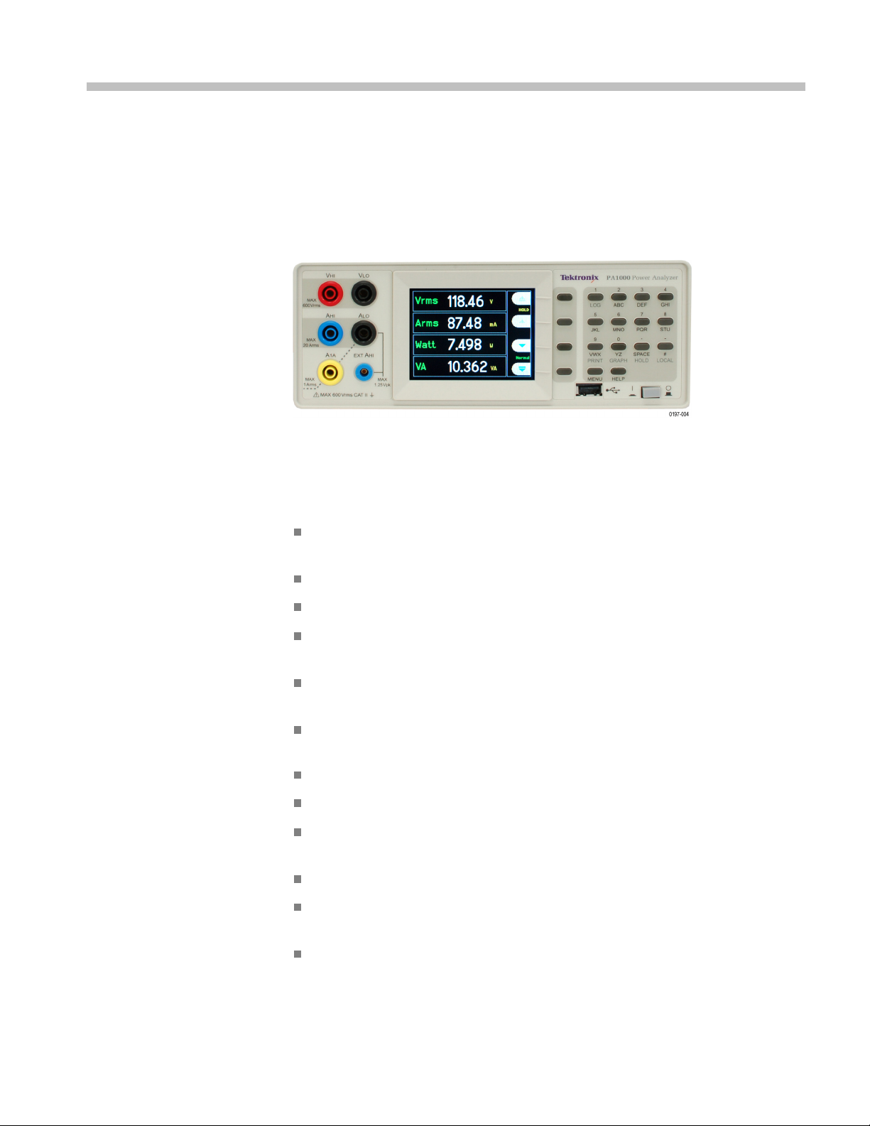
Figure 1: PA1000 Power Analyzer
Measures Watts, Volts, A mps, Volt-Amperes and Power Factor. Always
accurate, even on distorted waveforms.
testing.
Range of measurement from milliwatts to megawatts.
Quick access to results, graphing and menus.
Built-in energy analyzer (watt-hour integrator) for measuring energy
consumption over time.
Built-in 20 A and 1 A shunts to allow the easy measurement of a wide
dynamic range of currents.
Standby power measurement mode for fast and accurate low power
measurements.
IEC 62301 Compliance testing available with PWRVIEW software
Harmonic analyzer with built in spectrum display.
IEC Current Harmonics mode (requires PWRVIEW PC software) for IEC
61000-3-2 pre-compliance testing.
Bright color TFT display.
Compre
USB as standard.
Inrush current measurement mode for measuring switch-on and other transient
peak currents.
hensive range of computer interfaces including GPIB, Ethernet and
PA1000 Power Analyzer 1
Page 24

Introduction
Standard accessories
Ballast mode fo
r measuring the tube power of electronic ballasts.
Easy-to-use menu system with context-sensitive help.
Table 1: Standard accessories
Accessory Tektronix part number
Voltage lead set
USB 2.0 cable, A to B, 6 ft. length
Documentation CD
Power Cord
Country-specific power cord
One of the following:
North America
Universal Euro
United Kingdom
Australia
Switzerland (Option A5)
Japan
China (Option A10)
India
Brazil
No power cord or AC adapter (Option A99)
PA LEADSET
174-6053-xx
063-4519-xx
(Option A0)
(Option A1)
(Option A2)
(Option A3)
(Option A6)
(Option A11)
(Option A12)
Optional accessories
Table 2: Optional accessories
Accessory Tektronix part number
Breakout box (North America plug configuration)
Breakout box (Euro plug confi guration)
Breakout box (United Kingdom plug configuration)
Specialty current transducer for lamp ballast testing BALLAST-CT
Current clamp, 1 A - 200 A, for Tektronix Power Analyzers CL200
Current clamp, 0.1 A - 1200 A, for Tektronix Power Analyzers CL1200
Replacement lead set for Tektronix Power Analyzers (one
channel leadset)
2 PA1000 Power Analyzer
BB1000-NA
BB1000-EU
BB1000-UK
PA-LEADSET
Page 25

Introduction
Service optio
ns
Table 3: Service options
Option Description
Opt. C3 Calibration
Opt. C5 Calibratio
Opt. D1 Calibrati
Opt. D3 Calibrati
Opt. D5 Calibrat
n Service 5 Years
on Data Report
on Data Report 3 Years (with Option C3)
ion Data R eport 5 Years (with Option C5)
Service 3 Years
PA1000 Power Analyzer 3
Page 26
Getting started
Getting start
ed
Before you begin - safety
Carefully r
the Power Analyzer.
WARNING. To avoid possible electric shock or personal injury:
• By connecting the Power Analyzer to active circuits, the terminals and certain
parts inside the Power Analyzer are live.
• If possible, open the circuit before establishing a connection to the Power
Analyzer.
• Before connecting the circuits, ensure that the maximum measuring voltage and
maximum
• Do not use leads and accessories that do not comply with relevant safety
standards, as this could lead to serious injury or death from electric shock.
• Shunts and conductors can generate heat when in use and surfaces may burn
the skin.
Qualified personnel
This
persons who are familiar with the installation, assembly, connection, inspection
of connections, and operation of the analyzer and who have been trained in the
following areas:
ead and adhere to the following warning statements before you connect
voltage to earth g round (600 V
product may be operated only by qualified personnel. This means only
, CAT II) is not exceeded.
RMS
Installation
Switching on/off, enabling, earth-grounding and identification of electrical
circuits and services/sys tem s according to the applicable safety standards.
Maintenance and operation of appropriate safety gear, in accordance with the
applicable safety standards.
First aid.
Ensure that all perso ns using the de vice have read an d fully understood the
Operators Manual and safety instructions.
Mains connection m ust conform to these ranges/values: 100 – 240 V,
50/60 Hz.
The device may only be used under certain ambient conditions. Ensure that
the actual ambient conditions conform to the admissible conditions specified
in this manual.
Ensure this product is installed in such a way that its power cable is accessible
at all times and can easily be disconnected.
4 PA1000 Power Analyzer
Page 27
Getting started
Before each use
Connection sequence
Ensure that the
power and connecting cables as well as all acces sories and
connected devices used in conjunction with this product are in proper working
order and clean.
Ensure that any third-party accessories used in conjunction with the device
conform to the applicable IEC61010-031 / IEC61010-2-032 standards and are
suitable for the respective measuring voltage range.
WAR N ING. To avoid possible electric shock or personal injury:
When the measuring circuit is used to measure MAINS, the voltage to earth may
not exceed 600 V
in a CAT II environment.
RMS
For safety reasons, when connecting a circuit to the Power Analyzer, proceed
in the sequence outlined as follows:
1. Connect the Power Analyzer power cord to a properly grounded mains outlet.
The Power Analyzer is now connecte d to the protective earth ground wire.
2. Power on the Power Analyzer.
During use
3. Conne
ct the measuring circuit according to all instructions and as shown in
the connection diagrams in this manual.
For connection work, work in teams of at least two persons.
If you detect any damage to the housing, controls, power cable, connecting
leads, or connected devices, immediately disconnect the unit from the power
ply.
sup
you are in doubt as regards the safe operation of the device, immediate l y
If
shut down the unit and the respective accessories, s ecure them against
inadvertent switching on, and have them serviced by a qualified service
person.
PA1000 Power Analyzer 5
Page 28
Getting started
Power on
1. Check that the power analyzer is in good condition, with no signs of damage.
2. Follow the Connection Sequence described in the Before you begin - safety
section. (See page 4.)
3. After pressing the power switch at the front to on:
The PA1000 w
5–10 seconds.
During pow
version.
4. The instr
Figure 2: Initial power-on display
ument is now ready for use.
ill start its power-on sequence. This takes approximately
er on, you will see the PA1000 serial number and firmware
6 PA1000 Power Analyzer
Page 29
Getting started
Controls and c
Front panel
onnectors
Use this section to help familiarize yourself with the instrument operation.
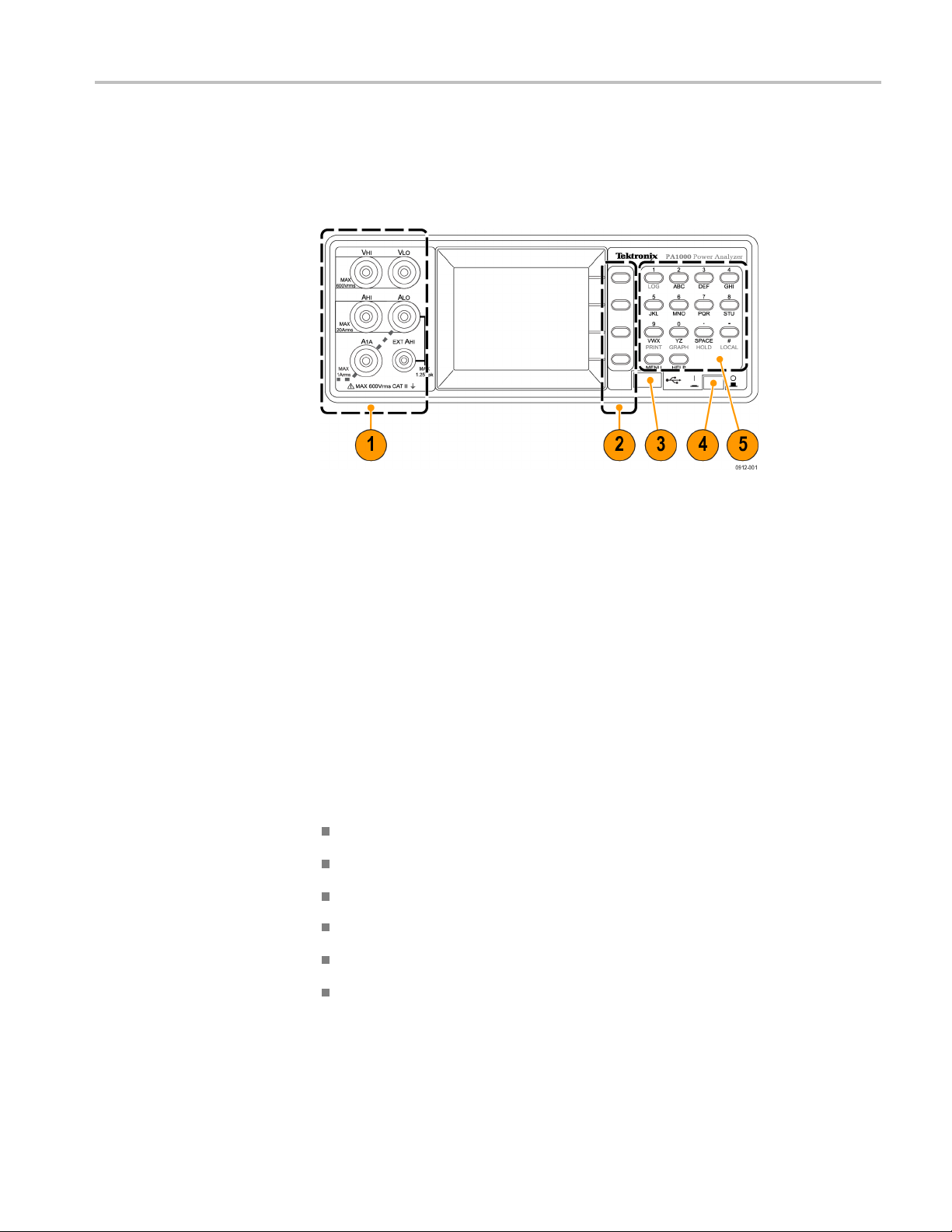
Figure 3:
1. Input ba
PA1000 front panel
nana jacks – For safe operation, use o nly the test lead set supplied
with the instrument. Typical connections for the power analyzer are shown
later in this section. (See Figure 5 on page 9.)
2. Soft keys – These push buttons control the screen -specific functions that
appear on the instrument display. (See Figure 9 on page 12.)
3. USB connection – Use this front-panel USB jack for saving instrument data
to your flash drive.
4. Power switch – Push button switch turns on the instrument power.
5. Alp
Key shortcuts.
hanumeric keypad – Use these keys to input alphanumeric information
and to perform functions such as displaying graphs. See Key shortcuts below:
Display main menu: Press MENU (toggle on/off)
isplay system help: Press HELP (toggle on/off)
D
Display hold: Press SPACE (toggle on/off)
Display graph: Press YZ (toggle betwee n graph and results)
Local control (from remote): Press #
Toggle Data Logging: Press STU or 1
PA1000 Power Analyzer 7
Page 30
Getting started
Rear panel
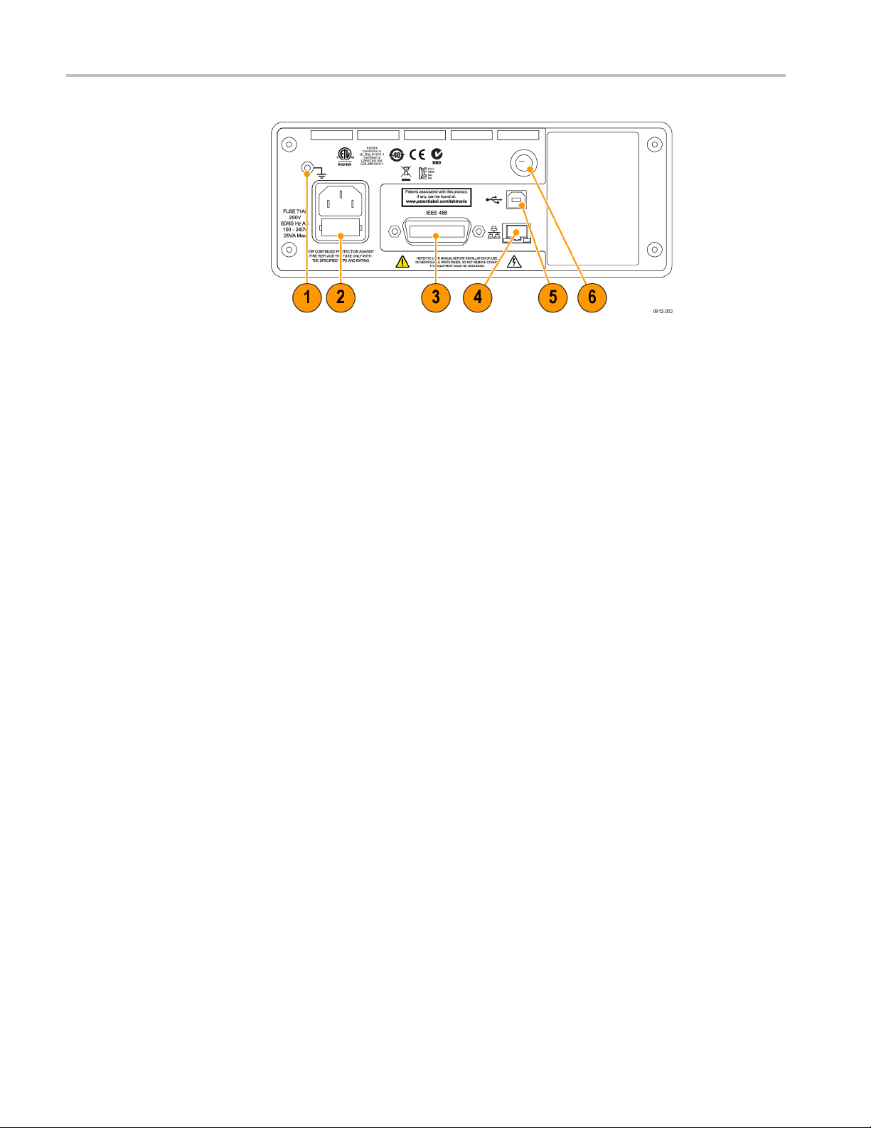
Figure 4: PA1000 rear panel
1. Ground lug – Attach the ground connection from the device under test (DUT)
to this rear-panel connector.
2. Power cord connector and line fuse – This connector accepts the
country-specific line cords that are available for the instrument. The line fuse
is replaceable; see Specifications for the correct fuse type.
mware upgrade
Fir
3. IEEE.488 (GPIB) connector – Use this connection to communicate to the
instrument over a GPIB bus.
4. RJ-45 (Ethernet) connector – Use this connection to communicate to the
instrument through an E thernet connection.
5. USB B connector – Use this connection to communicate to the instrument
through a USB connection.
6. Front-panel inputs fuse – The input circuitry is protected by this fuse. Refer
to Specifications for the proper replacement type.
For the best performance and compliance to the specifications and features
described in this manual, please ensure that the latest firmware is installed on your
PA1000. The firmware version of your PA1000 is displayed during power-on.
e latest version is available on our website at www.tek.com and installs over
Th
USB from a PC utility in less than 15 minutes. To locate the latest version of
the firmware (and PC software), go to ww w.tek.com, and browse to the "Power
Analyzers" "PA1000" page and then click on the software link or tab. (See
page 58, PA1000 firmware update utility.)
8 PA1000 Power Analyzer
Page 31

Getting started
Connecting to
the product under test
The PA1000 can m eas ure up to 600 V
4 mm terminals on the front panel. For measurements outside the range (low or
high power),
page 27, Connecting signals.)
To measure p
with the supply voltage and in series with the load current as shown below.
WAR N ING. To avoid injury always use good quality safety cables as supplied and
check that they are not damaged before use.
WAR N ING. If the peak voltage or current exc eeds the measurement capability of
the instrument, the results screen will be replaced with Over Range. At this point,
the input levels should be reduced ensure accurate measurements.
see the information on using current and voltage transducers. (See
ower, connect the measuring terminals of the PA1000 in parallel
and20A
RMS
RMS
or 1 A
directly using the
RMS
Figure 5: Typical PA1000 input connections
PA1000 Power Analyzer 9
Page 32

Getting started
Breakout Box
The simplest an
use a Tektronix Breakout Box. This provides a line socket for connection of the
product and 5 x 4 mm sockets for direct connection to the PA1000 terminals as
described above.
Figure 6: Breakout box
There are three versions of the breakout box, differing by the type of line socket:
120 V North America, 230 V Europe and 230 V United Kingdom. See Optional
accessories for ordering information. (See Table 2 on page 2.)
d safest way to make a connection to the product under test is to
10 PA1000 Power Analyzer
Page 33

Getting started
Connecting the
1. Using the test leads provided with the PA1000, make the voltage and current
connections between the breakout box and the input jacks on the PA1000.
(See Figure 7
NOTE. The VLO Source jack on the breakout box is designed for taking
measurements in low power, standby applications.
breakout box.
.)
e 7: Typical breakout box connections
Figur
2. Plug
3. Con
4. Po
For other information about the breakout box, refer to the BB1000 Instructions
at are included with the breakout box.
th
PA1000 Power Analyzer 11
the power cord from the unit under test into the receptacle on the
breakout box.
nect a power cord from the line source to the breakout box Line In
connector.
wer on the unit under test and begin taking measurements.
Page 34

Getting started
Default measu
rements
After you switch on the supply to the load, the PA1000 is ready to take
measurements. Note that it is not necessary to switch the PA1000 either off or
on when the lo
ad is being connected.
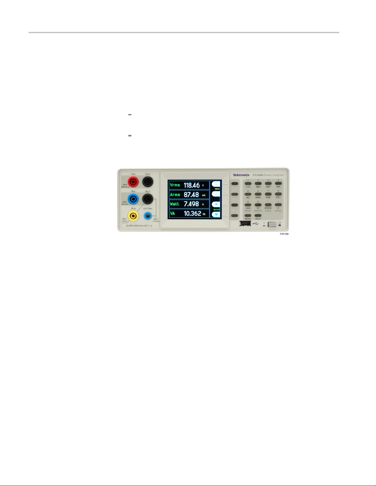
Figure 8: Default measurement display
The default display shows 4 values at one time. Each line clearly shows the
rement type ‘V
measu
’, the measured value, ‘118.46’ and the measurement
RMS
units, ‘V’. Normal engineering notationisusedtodescribeunits,e.g. mV=
milli-volts (10
The default measurements are V
–3
) and MW = mega-Watts (10+6).
RMS,ARMS
, Watts, Frequency and Power Factor.
To scroll through the measurements, use the 4 keys to the right of the display:
Figure 9: Display soft keys
12 PA1000 Power Analyzer
Page 35

Navigating the menu system
The menu system provides complete access to all settings of the PA1000. To
access the menu system, press the MENU key.
To return to the measurement display at any tim e, simply press the MENU key
again. With the menu system active, the 4 soft keys to the right of the display may
be used to navigate and select options.
Menu k eys
Getting started
Choosing measurements
to display
Figure 10: Menu keys
To choose the measurements on the display:
1. Press MENU to show the menu.
2. Press
displayed in the order s hown.
3. Use the
4. The measurement will be highlighted in red. To move the measurement use
the
5. Press
To remove a selected measurement, select it and press
Hint: To restore the default list, see the User Configuration Menu. (See page 26,
User configuration.)
to see the list of measurements. Measureme
and keys to select a measurement to display and press .
and keys.
to select the measurement.
nts with a
.
will be
PA1000 Power Analyzer 13
Page 36

Getting started
Data logging
The PA1000 can log data to a USB flash drive. The unit will log all selected
measurements into a comma separated values (CSV) formatted file that is stored
on the connected USB flash drive. Results will be logged approximately once
per second. The exact logging time interval will differ based on selected mode,
number of me
Prior to enabling data logging, insert a USB flash drive into the USB host port on
the front o
WARNING. If the U SB flash drive is removed while data logging is enabled, data
corruption will occur.
asurements and other settings.
f the PA1000.
Logging data
Data storage and format
To start
indicated by the current mode text flashing every second. To stop data logging,
press the 1 key on the PA1000 keypad.
The da
drive. The directory structure c reated will contain the last five digits of the serial
number of the PA1000 used and the date at the start of data logging. The file nam e
will reflect the time at the start of data logging in 24 hr format and will have a
.CSV extension.
For example, if a PA1000 with the serial number B010100 begins data logging on
28 June 2013 at 3:10:56 PM, the directory tree will be as shown below:
The first portion of the file will contain a header identifying the instrument used by
serial number and the time data logging began. The second portion of the file will
contain column headers for every measurement currently selected. Subsequent
lines will contain an indexed set of the measurements c urrently selected, in the
rder disp layed on the PA1000 screen.
o
data logging, press the 1 key on the PA1000 keypad. Data logging is
ta will be logged in a directory created by the PA1000 on the USB fl ash
Root Dir\PA1000\10100\20130628\15-10-56.csv
14 PA1000 Power Analyzer
Page 37

Getting started
The basic forma
year, month, day (YYYYMMDD) format respectively.
Figure 1
USB Fla
1: PA1000 logged data
sh Drive Requirements:
t of the data is shown below. Time and date will be in 24 hr and
Printing
The USB flash drive must be formatted with FAT12, FAT16 or FAT32 fi le
ms.
syste
Sector size must be 512 bytes. Cluster size up to 32 kB.
Only Bulk Only Mass Storage (BOMS) devices which support the SCSI or
AT command sets are supported. For more information on BOMS devices
rtoUniversalSerialBusMassStorageClass–BulkOnlyTransportRev.
refe
1.0, published by the USB Implementers Forum.
t USB memory devices meet the above requirements.
Mos
Printing directly from the PA1000 is not currently supported, but may be
implemented in a future software release.
PA1000 Power Analyzer 15
Page 38

Getting started
Unit configura
tion
Explanation of adjustment
(calibration) type
To view unit configuration data including hardware revision, firmware revision,
serial number, date of last adjustment (calibration), a nd verification, select:
System Configuration → Unit Configuration
On the unit configuration s creen there are 2 dates related to calibration. They are:
Last Verified – This is the date the PA1000 was last checked against
specification without any adjustments being made.
Last Adjusted – This is the date calibration information was last changed in
the PA1000.
16 PA1000 Power Analyzer
Page 39

The menu system
Navigation
The menu in the PA1000 is a powerful yet easy-to-use system for control of the
analyzer. See the Quick Start section of this manual for an overview of how to
access and use the menu system. (See page 13, Navigating the menu system.)
For help at any time while using the PA1000 press the HELP key at any time.
Menu items
Main menu
Measure
ments
To switch the display of the menu system off or on, press the MENU key at any
time.
To select a menu, press the key.
Choose the measurements to display.
To add a new measurement:
1. Select it
2. (Optional) Move the measurement
3. Press O K.
To remove a measurement, select it and press
Hint: To restore the default list, see the User Configuration Menu.
nformation on setup for harmonics and distortion factor, see System
For i
Configuration.
and and press .
and (does not apply to harmonics).
.
PA1000 Power Analyzer 17
Page 40

The menu system
Modes
Select mode
Choose this option to set the PA1000 into one of its operating modes. Each mode
is indicated on the front panel measurement display once set. The modes are:
Normal. Ideal for most general measurements.
Ballast. For measuring the output of electronic ballasts. See www.tektronix.com
for application notes on this subject. The frequency displayed is the ballast
switching frequency.
Inrush. For measuring the peak current during any event. Typically this is used to
measure t
keytosettheinrushcurrenttozero.
Standby power. A special mode in the analyzer that allows the user to set
a time window over which to accumulate pow er measurements. When set,
power measurements will update after each time window period, other available
measur
The currently displayed power measurement represents the amount of power
accumulated over the last time window only.
Integrator. For energy consumption (W-h) measurements over time. Ideal for
rating products whose energy consumption is not constant like washing machines
and
he peak current when a product is first switched on. Press the Reset soft
ements will update at the normal display update rate of 0.5 seconds.
refrigerators.
otes on changing mode
N
IEC current harmonics. This mode can be accessed using the PWRVIEW PC
software only. It enables pre-compliant current harmonic measurements to
be made consistent with IEC61000-3-2:2014 Ed.4 and IEC61000-4-7:2002 +
A1:2009.
When you change modes, the measurements that are displayed will change.
Adding a measurement to the display will only apply to the currently selected
mode. The number of available measurements a re different, depending on which
mode you are in. The same applies for remote communications since the "FRD?"
command,whichisusedtoreturnresults, only returns the results displayed on
the screen, in the order in which they are displayed.
The following table lists which m easurements are available in which mode, along
with which measurements are displayed by default for the selected mode . (See
Table 4 on page 19.)
18 PA1000 Power Analyzer
Page 41

The menu system
Table 4: Availa
ble measurements per mode
Mode
Measurement Normal Ballast Inrush Standby Power Integrator
V
RMS
A
RMS
Watts
X* X*
X* X* X* X*
X* X* X*
X
X* X*
X
VA X X X X
Var X X X X
Freq
PF
X* X*
X* X* X* X*
Vpk+ X X
Vpk– X X
Apk+ X X
Apk– X X
X
X*
X*
X*
X*
X* X*
Vdc X X
Vac X X
Vcf
Acf
XX X
XX
Vthd X X X
d
Ath
XX
ZX
RX
XX
Hr X
Whr
X*
VAhrs X
VArhr X
Ahr X
V-harm X X X
A-harm X X
V range X X X X X
A range X X X X X
X = Measurement available
X* = Displayed as default
PA1000 Power Analyzer 19
Page 42

The menu system
Setup mode
Also, dependin
g on which mode you change to, other settings may be changed:
When you change to any mode except Inrush mode, the voltage and the
current range
s will be set to auto range.
When you change to Inrush mode, the voltage and current ranges will be set
to the defau
lts set up under the Inrush mode setup.
Choose the mode that you want to set up.
Inrush set
up. Choose the default starting current range and the default starting
voltage range. Start with the maxim um range and then set the mode and make
measurements. Choose a lower range with the soft keys for more accuracy once
you begin to make measurements. The reset soft key sets the inrush current to zero.
Standby power setup. The time window is the time over which the PA1000
will ave
period specified in the time window, with the exception of V
rage the samples. Note that the measurements will only update at the
,Vcf,Frequency,
RMS
Vthd, and Vharmonics magnitude and phase which will continue to update every
0.5 seconds.
Integrator setup. The Integrator on the PA1000 operates in two methods, the
al Start Method and the Clock Start Method. In the Manual Start Method the
Manu
integrator will start and stop when the user presses the start/stop button and will
reset when the user presses the reset button.
In the Clock Start Method the PA1000 will use its real time clock to start the
integrator based on the date and time set up by the user. The user will also
configure a duration for the Clock Start Method that will stop the integrator at the
appropriate time.
The desired Start Method is configured in the Integrator Setup, Start Method
menu. Select Manual or Clock using the
key.
If Manual Start M ethod is selected, nothing more needs to be configured to run the
integrator. After the mode is selected, the user will use the start/stop
start and stop the integrator and the reset key (
Note: Use of the reset key (
) requires the integrator to be stopped. The Clock
) to reset the accumulated values.
key to
Start Method is configured in the Integrator Setup m enu. Here the user can
configure the start date and tim e and the duration. The starting time and the
starting date are entered in the current format of the PA1000, as shown at the
time they are entered. The duration is entered in minutes in the range shown on
the data entry screen.
20 PA1000 Power Analyzer
Page 43

Inputs
The menu system
Set up the measurement inputs – range , scale and low value blanking.
This menu may be used to set up the physical inputs of the PA1000. For normal
operation, (20 mA to 20 A
andupto600V
RMS
), it is not necessary to change
RMS
these settings from default.
Fixed/Auto ranging
Scaling
To select an Inputs menu item, use the
keys and then press for detailed
options.
For most me
asurements, auto-ranging is the best choice. Choosing a fixed range
may be useful if the voltage or current is changing continuously or has large peaks
that make the analyzer spend excessive tim e changing range.
Select
ltsorAmpsandpress
Vo
to choose the range. Changing the
measurement mode will often reset the voltage and current range to auto.
Scaling
can be used to adjust the PA1000 values to account for the transducer
ratio. The scaling factor will affect every measured value related to the input
to which it is applied.
When the 600 V and 20 A and 1 A inputs are used directly, then the default setting
for Volts and Amps scaling is 1.
To use the PA1000 with external voltage or current transducers, enter a sca le
factor to make the PA1000 display measurements with proper scaling, accounting
for the transducer ratio.
Select
Volts or Amps and press to enter the scale factor. See the Chapter
Using External Voltage and Current Transducers for further information.
Frequency source
To make accurate rms measurements, the PA1000 must first determine frequency.
Normally the PA1000 detects frequency from the voltage signal using proprietary
algorithms. If no voltage signal is present, or it is a chopped waveform, then it
may be necessary to select Amps as the frequency source. Select Volts or A mps
Bandwidth
Frequency Source using the
The default bandwidth of 1 MHz is ideal for most measurements. Choose 'High'
keys and press to confirm.
to set the 1 MHz bandwidth. The measurement bandwidth may be reduced to
10 kHz or 50 kHz by choosing the respective setting. This setting introduces
a 10 kHz or 50 kHz digital FIR filter, depending on the selection, and may be
used to reduce unwanted high-frequency noise. Choose 10 kHz or 50 kHz
bandwidth when making low power standby measurements or for compatibility
with low -bandw idth instrumentation.
PA1000 Power Analyzer 21
Page 44

The menu system
Frequency filter
Shunts
For optimal fre
quency measurement perform ance when measuring volta ge signals
below 20 kHz, the Low Pass frequency filter can be engaged. If the signal level on
the voltage signal is less than 10% of range and the frequency is known to be less
than 20 kHz, the Low Pass frequency filter is recommended. Select Auto or Low
Pass using the
keys and press to confirm.
NOTE. The frequency filter does not affect the voltage measurement. The filter
is for the frequency detection.
The PA1000 is fitted with two internal shunts. The 20 A shunt is suitable for
measurements from 20 mA to 20 A
from 20 μA
to 1 A. These ranges may be extended by the use of suitable current
. The 1 A shunt is suitable for measurements
RMS
transducers from μAtoMA.
Some cur
rent transducers (including simple resistive shunts) produce a voltage
that is proportional to current. External Shunt Inputs are provided on the PA1000
for use with current transducers that provide a voltage output. Because the 0 V is
common to both the internal and external shunts, only one type may be connected
at any time.
Select Internal (20 A), Internal (1 A) or External Shunt using the
and press
to confirm.
keys
Blanking
Averaging
Further information is available. (See page 27, Connecting signals.)
mally enabled. Select Disable to measure voltage or current that are small.
Nor
If blanking operates on either voltage or current then all related measurements
would be blanked including W, VA and PF. S elect Disable or Enable using the
keys and press to confirm.
rmally disabled. Select Enable to allow the PA1000 to average results, for
No
more stable measurements of fluctuating signals. Averaging depth is set at four
when enabled. All results, including harmonic magnitude and phase, are averaged
except for ranges (when selected for display) and cumulative measurements
(Whrs, VAhrs, VArHrs, Ahrs, and Hrs). Select Disable or Enable using the
keys and press to confirm.
22 PA1000 Power Analyzer
Page 45

Graphs
The menu system
To set up the graphical displays of the PA1000, select the graph type using the
keys and press for options.
Hint: Use the YZ key to toggle between graphic and numeric displays.
Waveform graph
Harmon
ic bar chart
This will display the voltage, current and (optionally) the Watts waveform. The
scale of the graph is set automatically according to the selected range and scaling.
Display of the Watts graph may be disabled.
Use the
Graph. Select ‘Watts’ to add the instantaneous watts waveform to the display.
NOTE. Waveforms will only be displayed when there is a valid frequency. DC
waveforms will not be displayed.
Select Voltage or Current harm onic bar chart using the keys and press
for details.
The scale is the maximum amplitude that will be displayed. Set the scale to be
similar to the rms value to see an overview of the spectrum. To view smaller
harmonics in more detail a smaller scale may be set.
If the harmonic exceeds the set scale it will be shown with a white cap on the
top of the bar.
The scale only applies when the harmonic format is absolute measurements. If
percentage measurements are used, then the scale is automatically set to 100%.
The fundamental harmonic (H1) will be displayed as 100%.
keys to select Show and then press to display the Waveform
The right
amplitude and phase are shown at the top of the screen. The selected harmonic
is shown in yellow. Select
bar chart (voltage or current).
Integration graph
PA1000 Power Analyzer 23
elect Integration g raph using the
S
The Integration Graph menu allows the user to select what value to display on
the graph and the vertical scale of the graph (in units of the value selected). The
horizontal scale of the graph is only for display purposes. The integration will
continue until stopped by the user using the start/stop button
key
NOTE. Useoftheresetkey
and left arrow keys may be used to select the harmonic whose
Show and press to display the harmonic
keys, press to configure.
.Thereset
can be used to reset the accumulated values.
requires the integrator to be stopped.
Page 46

The menu system
Interfaces
Ethernet configure
GPIB address
When the graph i
PA1000 must be in Integrator mode for the graph to start.
This menu may be used to set up the interfaces of the PA1000.
To select set up an interface, use the
options.
Enter the GPIB address and press OK.
Default address is 6. The address is unchanged after a “*RST” or “:DVC”
command.
The PA1000 offers Ethernet communications through an Ethernet port using
TCP/IP.
The Ethernet port will make a TCP/IP connection on port 5025. Port 5025 is
designated by the Internet Assigned Numbers Authority (IANA) to be a SCPI port.
Use the IP Selection Method menu, and the
assigned IP address, by selecting “Set IP using DHCP”, or a fixed/static IP address
by selecting “Fix IP Address” with the
sconfigured, select Show to view the graph. Note: The
keys, and then press for detailed
keys to opt for a dynamically
button.
System configuration
Harmonics setup
To view the current IP settings, choose “Current IP Settings” in the Ethernet
Setup menu. This allows you to view the current IP address, subnet mask, and
default gateway.
To configure the static IP address, choose “Static IP Settings” in the Ethernet
Setup menu. This allows you to enter the IP address, the subnet mask and the
default gateway. After entering the relevant data, press the OK button in each
nu to apply.
me
The Ethernet m ode (Static/DHCP), IP address, default gateway and subnet mask
reunchangedaftera“*RST”or“:DVC”command.
a
Set up harmonics, distortion, the clock and auto zero.
To select a menu item, use the
For both voltage and current harmonics, a number of different parameters can be
set. These setting are independent of the m ode that is currently selected:
keys and then press for detailed options.
24 PA1000 Power Analyzer
Page 47

The menu system
Distortion setup
Sequence: All o
Range: The maximum harmonic (up to 50)
Format: Displa y harmonics as absolute values or as a percentage of the
fundamental (1st) harmonic.
For both voltage and current harmonics, a number of different parameters can be
set. These settings are independent of the mode that is currently selected. Four
following settings can be made for distortion:
Formula: Series (Total Harmonic Distortion) or difference (Distortion Factor).
(The default = series formula)
Sequence: Include all harmonics or only odd harmonics in the series formula.
(default = all harmonics)
Range: The maximum harmonic to be included in the series formula. (default
=7)
DC (H0): Include or exclude D C in the series formula. (default = exclude)
Reference: rms or 1st harmonic. (default = rms)
For details of the actual equations used, (See page 76, Measured parameters.)
r odd harmonics only
Auto and Manual Zero
Normally the PA1000 will cancel any small dc offsets in the m easurement
automatically. This feature i
Auto Zero. Auto Zero should always be enabled except in certain applications
such as Inrush current measurement.
Select
Manual Zero. Manual zero is a procedure normally carried out during periodic
calibration of the PA1000. The procedure cancels dc offsets in the measurement
system by making measur
We recommend a manual zero is performed:
During routine service (calibration or repair).
After firmware upgrade.
Before very low-level measurements (for example below 100 uA).
To perform a manual zero:
1. Allow the PA1000 to warm up for 1 hour.
2. Remove all voltage and current inputs.
3. Select Run Manual Zero Offset and press
prompt you after a few seconds when the process is complete.
Disable and Enable and press to confirm.
sreferredtoasAutoZero.
ements with nothing connected to the input terminals.
to confirm. The analyzer will
PA1000 Power Analyzer 25
Page 48

The menu system
Unit configu
User confi
Clock setup
ration
guration
These options m
menu item, use
Set Time - Enter the time using the format shown and press OK to confirm.
Set Date - Enter the date using the format shown and press OK to confirm.
Time Format - Selec t
Date Format - Select
The Unit Configuration menu displays the hardware revision, firmware revision,
serial number, date of last adjustment and verification.
The PA1000 has the ability to store and recall up to 5 different setups.
To select a menu item, use the
The first option is to ‘Load Default’. Choosing this option sets every menu option
of the PA1000 to its factory default.
ay be used to che ck or set the PA1000 i nternal clock. To select a
the
keys and then press for detailed options.
12 Hour or 24 Hour and press to confirm.
the required date format and press to confirm.
keys and then press for detailed options.
V
iew
Zoom
The other menu items (Default ‘CONFIGURATION n’) may be used to store
and recall all settings of the PA1000.
For each User Configuration you can go into a sub menu and you may:
Apply
Rename – give the configuration a meaningful name. A name can be up to
Save Current – save a configuration. This is always the com plete setting o f
NOTE. Loading a configuration that has never been saved will result in an error
message. The current configuration of the unit will not be changed.
To select a menu item, use the keys and then press for detailed options.
Use the Zoom function to select the number of measurement results that are
displayed on the instrument screen. The selections are either 4 or 14. Select
— either 4 results or 14 results display and press to confirm.
– apply the saved configuration.
aracters.
16 ch
PA1000 at the time you choose this option.
the
26 PA1000 Power Analyzer
Page 49

Connecting signals
Connecting si
Input overview
Voltage
Curren
gnals
WAR N ING. To avoid possible electric shock o r personal injury:
· Do not touch connections, internal circuits or measuring devices that are not
connected to earth ground.
· Always ad
page 5, Connection sequence.)
Signal le
Voltagesofupto600V
VHI and VLO safety sockets at the front of the PA1000.
Currentsofupto20A
t
AHI and ALO safety sockets at the front of the PA1000 Alternatively, if you
are making measurements of less than 1 A
measu
here to the instructions regarding the sequence of connection. (See
ads are connected on the front of the PA1000.
may be connected directly to the red and black 4 mm
RMS
may be connected directly to the blue and black 4 mm
RMS
,2Apk, connect the current to be
RMS
red between the yellow A1A and black ALO connections.
External current input
The external current input, EXT AHI, accepts voltages up to 1.25 V
proportional to the current being measured. This input allows a very wide range
xternal current transducers to be connected, from low -milliamp current shunts
of e
to mega-Amp current transformers. For each type of transducer, the PA1000 may
be scaled to read the correct current. (See page 21, Inputs.)
The choice of current transducer will depend on:
he current being measured, including peaks and transients
T
The accuracy required
The bandwidth required: Unless the waveforms are purely sinusoidal, a
bandwidth in excess of the fundamental frequency will be required.
Whether there is DC current present
Convenience of connection – that is, using a clamp-on current transformer,
with jaws that open, for quick connection in a fixed wiring loom.
The effect of the transducer on the circuit
peak
that are
PA1000 Power Analyzer 27
Page 50

Connecting signals
To connect a si
mple current transformer
To use a conventional current transformer (CT) like the Tektronix CL series
(or any other transducer with a current output), connect the normal AHI and
ALO inputs of
manufacturer’s instructions for the safe use and installation of the transducer.
Normally th
point of an arrow or a + symbol. Connect this terminal to the a ppropriate AHI
input of the PA1000.
Figure
12: Current transformer connections
the PA1000 to the outputs of the current transformer. Follow the
e positive or HI output of the transducer will be m arked with the
Current scaling
A current transformer produces an output current that is proportional to the load
ent being measured.
curr
To measure the correct current on the PA1000, use the scaling function of the
lyzer to scale, or multiply, the CT output current.
ana
For example, the CL200 is a 1000:1 CT. W hen measuring 100 A, its output is
mA. To scale this on the PA1000, a scale factor of 1000 must be entered:
100
Press MENU
Select
Select ‘Scaling’ and press
Select ‘Amp s’ and press
Typethenewscalefactor(1000)
Press
Press MENU to return to the measurement display.
The PA1000 is now ready to make m easurements using a CT.
‘Inputs’ and press
28 PA1000 Power Analyzer
Page 51

To connect an external resistive shunt
Using a resistive shunt is a straightforward method of extending the current
measuring range of the PA1000. The shunt resistor is connected in series with the
load and the voltage across the shunt is directly proportional to current.
That voltage may be connected directly to the External Current Inputs of the
PA1000.
Connecting signals
For example, a 1 milliohm shunt is used to measure 200 A
RMS
.
1. Check that the voltage that will be generated is suitable for the PA1000
V=IxR(Ohm’slaw)
Vshunt = I x Rshunt
Vshunt = 200 x 0 .001 Ohms
Vshunt = 0.2 V
This is well within the 1.25 V
rating of the External Current Inputs on the
pk
PA1000.
2. Con
nect the shunt in series with the load and to the EXT AHI and ALO
inputs as shown.
Figure 13: External resistive shunt connections
WAR N ING. AHI, A1A, EXT AHI and ALO are connected inside the PA1000 via
a low impedance shunt. To avoid errors and a risk of electric shock, remove all
connections to AHI and A1A.
3. Set up the PA1000 to measure current from the EXT AHI and ALO terminals.
Press MENU
Select
Inputs and press
Select Shunts and press
PA1000 Power Analyzer 29
Page 52

Connecting signals
Select Externa
Press MENU to return to the measurement display.
4. Scale the measurement on the display.
The default scale is 1 V = 1 A.
In this example where R = 0.001 Ohms. The scaling factor is specified in
Amps per Volt, so in this case, the scaling factor is 1000.
To enter a scale factor for current:
Press MENU
Select
Select Scaling and press
Select Amps and press
Type the new scale factor (1000)
Press
Press MENU to return to the measurement display.
The PA1000 is now ready to make measurements using an external shunt.
Inputs and press
l and press
To connect a transducer with a voltage output
These trans
bandwidth. They may be of the hall effect or Rogowski coil type.
The procedure is similar to that of installing an external shunt as described above.
1. Follow the manufacturer’s instructions for the safe use and installation of
the transducer.
2. Connect the voltage output to the EXT-HI an d A-LO terminals of the PA1000
as above.
3. Select Inputs – Shunts – External as above.
Press MENU
Select
Select Shunts and press
Select External and press
Press MENU to return to the measurement display.
4. Select and input a scale factor. These types of transducers are often rated in
terms of m V / amp. For example, a transducer with an output of 100 mV / amp
ducers contain active circuits that help to improve performance at high
Inputs and press
30 PA1000 Power Analyzer
Page 53

Connecting signals
is the equivale
scaling from Volts per Amp to the desired Amps per Volt, invert the value.
Using the above example, 100 mV / Amps is equivalent to 10 Amps / Volt.
Press MENU
Select
Select Scaling and press
Select Amps and press
Type the new scale factor (such as 0.1)
Press
5. Press MENU to return to the measurement display.
The PA1000 is now ready to make measurements using a current transducer with
a voltage output.
nt of a 100 milliohm external shunt resistor. To convert the rated
Inputs and press
Figure 14: Transducer with voltage output connections
To connect a voltage transfor
The PA1000 may be used with a voltage transformer (VT) or other transducer to
extend its measuring range. Follow the manufacturer’s instructions for the safe
use and installation of the t
The output of the transducer is connected to the normal VHI and VLO terminals.
Normally, the positive or HI output of the transducer will be marked with the point
of an arrow or a + sym bol. Connect this terminal to the VHI input of the PA1000.
Voltage scaling
PA1000 Power Analyzer 31
A voltage transformer (VT) produces a voltage output, which is proportional to
the voltage being measured.
To measure the correct voltage on the PA1000, use the scale function of the
analyzer to scale, or multiply, the VT output current.
mer / transducer
ransducer.
Page 54

Connecting signals
For example, wh
be used.
Press MENU
Select
Select Scaling and press
Select Vo l t
Use the key to clear the entry.
Type the n ew scale factor (1000)
Press
Press MENU to return to the measurement display.
The PA1000 is now ready to make measurements using a VT.
en measuring with a 1000:1 VT a scale factor of 1000 must
Inputs and press
s and press
Figure 15: Voltage transformer / transducer connections
32 PA1000 Power Analyzer
Page 55

Remote operation
Overview
You can use remote commands for the PA1000 to perform high speed, complex
or repetitive measurements. The PA1000 can communicate via GPIB, Ethernet
or USB.
Remote operation
Figure 16: Communication ports
1. GPIB
2. Ethernet
3. USB
Interfacing with USB systems
The PA1000 supports USB control using the Test and Measurement class.
A detailed pin description of the port, along with speed and connection
information is given in the specifications. (See page 75, USB peripheral.)
Interfacing with Ethernet systems
The PA1000 supports Ethernet control using a 10Base-T network.
See Ethernet port for more information on the Eth ern et connection. (See page 75,
Ethernet port.)
See Ethernet con figure for information on how to set up the Ethernet addressing
information. (See page 24, Ethernet configure.)
PA1000 Power Analyzer 33
Page 56

Remote operation
Interfacing w
Status repo
rting
Status byte
ith GPIB systems
The PA1000 s upports control via a GPIB port.
See IEEE 488/GPIB for a detailed pin description of the GPIB connector. (See
page 74, IEEE 488 / GPIB .)
The PA1000 uses a status byte similar to IEEE488.2. The PA1000 Status Byte
Register (STB) contains the ESB and DAS bits. These two bits indicate a
non-zero
Status R egister (DSR) respectively.
The ESR a
set by the user. These enable registers act as a mask to reflect chosen elements of
the appropriate status registers to the Status Byte Register. Setting the appropriate
bit of the enable register to 1 configures transparency.
If a status register is read, that register is reset to zero.
state in the Standard Event Status Register (ESR) or the Display Data
nd DSR each have enable registers, ESE and DSE respectively, that is
34 PA1000 Power Analyzer
Page 57

Remote operation
Status Byte Register (STB)
DisplayDataStatus
Register (DSR )
Read by “*STB?”
Bit 5 - ESB Summary bit to show standard event status.
Bit 0 - DAS Summary bit to show display d ata available.
Read by “:D
initialized to zero. When read using the “:DSR?” command the register bits are
cleared as listed below.
Bit 4 - OVV. Set to indicate there is a voltage range overload. Automatically
cleared when range overload clears.
.
SR?” or in summary by *STB? DAS bit. On power-up DSR is
Bit3-OVA. Set to indicate there is a current range overload. Automatically
cleared when range overload clears.
Bit1-NDV. Set to indicate that new data has become available since the last
:DSR? command. Cleared when read.
Bit 0 - DVL. Set to indicate the availability of data. Cleared when read.
PA1000 Power Analyzer 35
Page 58

Remote operation
Display Data Status Enable
Register (DSE)
Standard Event S tatus
Register (ESR)
Read by “:DSE?”
Bit4-OVV. Enable OVV bit in DSR.
Bit3-OVA. Enable OVA bit in D SR.
Bit1-NDV. Enable NDV bit in DSR. (Default to enabled on power-up.)
Bit0-DVL. Enable DVL bit in DSR. (Default to enabled on power-up.)
Read by “*ESR?” or in summary by the ESB bit in STB.
Bit5-CME. Command error; command not recognized.
and set by “:DSE <value>”.
Standard Event S tatus
Enable Register (ESE)
Command listing
Read by “*ESE?” and set by “*ESE <value>”. Cleared when read.
An invalid command is reported in the DSR register by setting a flag in the
Standard Event status Register. The fl ag shall be cleared when the register is rea d
“*ESR?”. An invalid query can have an unpredictable result, and may require that
you power-cycle the unit and/or the PC.
Bit5-CME. Enable CME bit in ESR. (Default to enabled on power-up.)
The following conventions are used in the next section to describe the command
syntax:
Square brackets indicate optional parameters or keywords [ ]
Triangle brackets indicate values to be specified < >
Vertical bar indicates the choice of parameters |
36 PA1000 Power Analyzer
Page 59

Remote operation
Commands and re
sponses are sent as ASCII strings terminated with a line feed.
The PA1000 is not case sensitive and white space characters are ignored except
where required between command and parameter.
Multiple commands cannot be sent in a single string where a ‘;’ character is used
at the end of each command.
For all commands where a parameter i s s upplied, one or more spaces are
required between the end of the command and the first paramete r. For example,
“:CAL:DATE 1” will work. “:CAL:DATE?1” will cause a time out error.
All non-common commands (those with ‘*’ as the first character) must have a
leading colon ‘:’. Although the IEEE 488.2 standard does not require this, the
PA1000 does. For example, :avg? works, but Avg? does not. :avg:aut works but
avg:aut does not.
The list of commands is split into relevant sections. In general each section
corresponds to a menu option from the main menu on the PA1000.
IEEE 488.2 standard commands and status commands
*IDN?
Unit identity
Syntax *IDN?
Return format Tektronix, PA1000, serial number, firmware version
Description
The serial number is the serial number of the product. The firmware
ion is the version of the firmware suite.
vers
*CLS
*ESE
Clear event status
tax
Syn
Description
S
*CL
ears the standard event status register to 0
Cl
Set standard event status enable register
Syntax *ESE <flags>
Where flags = value for enable register as a decimal 0 – 255
Default
Description
32
Sets the bits that are enabled in the standard event status register. The
status enable register uses the same bit definitions as the standard event
status register
PA1000 Power Analyzer 37
Page 60

Remote operation
*ESE?
*ESR?
*RST
Read standard e
Syntax *ESE?
Return format
Description Returns the v
vent status enable register
0 - 255
alue in the standard event status enable register.
Read event status register
Syntax *ESR?
Return format
Description Returns the value in the standard event status register, AND’ed with the
0 - 255
value in the standard event status enable register. The event status
register is cleared once it has been read
Reset device
Syntax *RST
Description
Resets the status reporting and returns the settings to default values
(performs the same action as Load Default Configuration menu option on
the front panel)
*STB?
:DSE
:DSE?
Tip. Allow 5 – 10 seconds after *RST has been sent prior to executing further
commands to allow all defaults to processed and set.
Read status byte
Syntax *STB?
Return format
Description Returns the value in the status byte, masked by the service request enable
0 - 255
register. Once read, the status byte is cleared to 0
SetDataStatusEnableRegister
Syntax :DSE <flags>
Default
Description
255
Sets the bits that are enabled in the display status register
Read Data Status Enable Register
Syntax :DSE?
Return format
Description Returns the value in the data status enable register
0 – 255
38 PA1000 Power Analyzer
Page 61

Remote operation
Unit infor
:DSR?
:DVC
Read Data Statu
Syntax :DSR?
Return format
Description Returns the v
Device clear
Syntax :DVC
Description
mation commands
The unit information commands are commands that are used to return information
on the unit beyond the information returned by the *IDN? command.
:CAL:DA
TE?
Calibration date
Syntax :CAL:DATE? <date type>
Return format Appropriate calibration date in the format dd-mm-yyyy
Description
sRegister
0 – 255
alue in the data status register, AND’ed with the value in the
data status enable register. The data status register is cleared once it
has been read
Resets the unit configuration to default values.
<date type> is 1 through 2
Returns the calibration date from the PA1000. <date type> can be either:
1=Dateverified
2 = Date adjusted
PA1000 Power Analyzer 39
Page 62

Remote operation
Measurement selection and reading commands
These commands are related to selecting the measurements required and returning
those results.
:SEL
Select results
Syntax :SEL:CLR
:SEL:<measurement>
Where <measurement> is:
VLT - Volts rms
AMP - Amps rms
WAT - Watts
VAS - VA
VAR - VAr
FRQ - Frequency
PWF - Power factor
VPK+ - Volts peak (positive)
VPK- - Volts peak (negative)
APK+ - Amps peak (positive)
APK- - Amps peak (negative)
VDC - Volts DC
ADC - Volts DC
VCF - Voltage crest factor
ACF - Amps crest factor
VDF - Volts Distortion Factor
ADF - Amps Distortion Factor
IMP - Impedance
RES - Resistance
REA - Reactance
HR - Integrator time *1
WHR - Watt Hours *1
VAH - VA Hou rs *1
VRH - VAr Hours *1
AHR - Amp Hours *1
VRNG - Voltage range
ARNG - Amps range
VHM - Volts harmonics
AHM - Amps harmonics
*1 – These results are only available
for displaying / returning when in
integrator mode.
Description
:SEL determines which results
are displayed on the screen also
the results returned by the FRD?
command. To see the currently
selected command the “FRF?”
command should be used.
SEL:CLR clears all the results.
40 PA1000 Power Analyzer
Page 63

Remote operation
:FRF?
:FRD?
Read selec t ed r
Syntax :FRF?
Description
esults
FRF? command is used to return a list o f the displayed r esults. The actual
result is not r eturned. The return format is:
<number of me
<measurement 1>,<measur ement 2>,…. and so forth.
<number of measurements selected> is the number of measurements
selected us
<number of results returned> equates to the number of rows on the display
used. When harmonics are selected, the number of results returned will
exceed the n
<measurement 1> and so forth, is the name of the measurement selected.
The returned data will be the same as the label used on the results display.
For harmon
Each value will be returned separated by a comma
Read foreground data
Syntax :FRD?
Description
The FRD commands returns results from the analyzer. The results are
returned in the order in which they are displayed on the screen. Each
result is a floating point number separated by a comma
The sequence is determined by order in which results are displayed on
the front panel.
asurements selected>, <number of results returned>,
ing either the front panel or the SEL command
umber of measurements selected
ics “Vharm” and “Aharm will be returned.
Measurement configuration commands
Measurement configuration commands correspond to the Measurement
uration Menu.
Config
:HMX:VLT/AMP
Commands for configuring the display of harmonics.
Harmonics configuration
Syntax :HMX:VLT:SEQ <value>
:HMX:AMP:SEQ <value>
Where <value> equals 0 for odd and even and 1 for odd only.
Description
Syntax :HMX:VLT:RNG <value>
If harmonics measurements are selected (see :SEL), the PA1000 can
display all harmonics, or just the odd number harmonics from the first
harmonic up to the number specified.
:HMX:AMP:RNG <value>
Where value> = the maximum harmonic to be display in the range of
1 to 50.
PA1000 Power Analyzer 41
Page 64

Remote operation
Harmonics configuration (cont.)
:HMX:THD
Description
Syntax :HMX:VLT:FOR <value>
Description
If harmonics measurements are selected (see :SEL), the PA1000 will
display all the harmonics up to the number specified by <value >. The
harmonics displayed can be restricted to odd numbered harmonics only
using the harmonic sequence command.
:HMX:AMP:FOR <value>
Where <value>
= 0 absolute values
= 1 percentage values
If harmonics measurements are selected (see :SEL), the PA1000 can
display all harmonics (except the first) as an absolute v alue or as a
percentage of the fundamental (first) harmonic.
Commands for setting up the total harmonic distortion measurements.
Total harmonic distortion setup
x
Synta
ription
Desc
tax
Syn
Description
Syntax :HMX:THD:RNG <value>
Description
Syntax :HMX:THD:DC <value>
Description
:HMX:THD:REF <value>
<value> = 0 fundamental
Where
=1rms
For total harmonic distortion (THD) readings (also known as the series
formula), the reference on the denominator of the equation can be either
ms reading or the fundamental harmonic reading.
the r
X:THD:SEQ <value>
:HM
Where <value> = 0 for odd and even
= 1 for odd only
For total harmonic distortion (THD) readings (also known as the series
rmula), the harmonics used in the measurement can include all
fo
harmonics up to the specified number or only the odd harmonics.
Where <value> = the maximum harmonic to be display in the range of
to 50.
2
or total harmonic distortion (THD) readings (also known as the series
F
formula), <value > is used to specify the maximum harmonic number
used in the formula.
Where <value> = 0 for exclude
= 1 for include
For total harmonic distortion (THD) readings (also known as the series
formula), the formula can either include or exclude the DC component.
42 PA1000 Power Analyzer
Page 65

Remote operation
:HMX:THD:FML
:HMX:THD:Hz
Mode setup commands
Commands for se
tting up the total harmonic distortion formulas.
Total harmonic distortion setup
Syntax
Description
:HMX:THD:FML <value>
Where <value>:
= 0 — series (THD)
= 1 — difference (DF)
For total harmonic distortion (THD) readings (also known as the series
formula), the formula can either include or exclude the DC component.
Command for including or excluding THD harmonic zero.
Total harmonic distortion setup
Syntax
Description
:HMX:THD:Hz <value>
Where <value> = 0 — exclude
= 1 — include
For total harmonic distortion (THD) readings, the command can either
include or exclude the frequency component.
:MOD
The mode set up commands correspond to the Modes menu. (See page 18,
Modes.
) They are used to control how the PA1000 is configured to measure
parameters in certain conditions.
Mode
Syntax :MOD:INR (inrush mode)
:MOD:NOR (normal mode)
:MOD:BAL (ballast mode)
:MOD:SBY (standby power mode)
:MOD:INT (integrator mode)
Description This command sets the mode.
Syntax :MOD?
Return format Mode number from 0 to 4.
Description
This command will return a reference to the active mode.
The returned values are:
0 – Normal Mode
1 – Ballast Mode
2 – Inrush Mode
3 – Standby Power Mode
4 – Integrator Mode
PA1000 Power Analyzer 43
Page 66

Remote operation
:MOD:INR:ARN
:MOD:INR:CLR
:MOD:INR:VRNG
:INT:CLK:
DATE
Inrush current
G
Syntax :MOD:INR:ARNG <value>
Description This c ommand sets the inrush current range.
range
<value> = 1 through 10.
Inrush clear
Syntax :MOD:INR:CLR
Description This command clears the Apk value when in Inrush mode.
Inrush voltage range
Syntax :MOD:INR:VRNG <value>
<value> = 1 through 7.
Description This c ommand sets the inrush voltage range.
Set date
Syntax INT:CLK:DATE xxxxxxxx
xxxxxxxx means dd_mm_yyyy, or mm_dd_yyyy, or yyyy_mm_dd according
to the Date Format settings in the Main Menu -> System Configuration ->
Clock -> Date Format.
Description
Sets the start date for the integrator when configured for Clock Start
Method. Start date sent in current PA1000 date format.
:INT:CLK:DUR
:INT:CLK:TIME
Set duration
Syntax :INT:CLK:DUR <value>
value> ≤ 100,000)
he duration of the integrator, in minutes, when configured for Clock
Description
(1.0 ≤ <
Sets t
Start Method.
Set start time
Syntax :INT:CLK:TIME xx_xx_xx
xx_xx_xx stands for hh_mm_ss for 24 hr time format or hh_mm_ss (A or
P) for AM/PM time format.
Description
Sets the start time for the integrator when configured for Clock Start
Method. Start time sent in current PA1000 time format.
44 PA1000 Power Analyzer
Page 67

Remote operation
:INT:MAN:RUN
:INT:MAN:STOP
:INT:RESET
:INT:START
Start integrat
Syntax
Description
ion
:INT:MAN:RUN
Starts integration when in Manual Start Method. Requires integration
mode active, manual start selected and integration not running.
Stop integration
Syntax INT:MAN:STOP
Description
Stops integration when in Manual Start Method. Requires integration
mode active, manual start selected and integration running.
Reset integration
Syntax :INT:RESET
Description Resets integration values. Requires integration mode active and
integration not running.
Start me thod
Syntax :INT:START <value>
<value> = 0 → Manual Start Method
<value> = 1 → Clock Start Method
Description
Selects either Manual Start Method or Clock Start Method.
Input setup commands
:RNG
The input setup commands correspond to the Inputs menu. (See page 21, Inputs.)
They are used to control how signal inputs to the PA1000 are channelled and
controlled.
Ranging
Syntax :RNG:VLT | AMP:FIX <range>
:RNG:VLT | AMP:AUT
VLT = set voltage ranging
AMP = set current ranging
FIX = Fixed ranging
AUT = auto ranging
Where <range> = range number from 1 to 10.
Description
Sets the range.
The range numbers for each input are defined below:
PA1000 Power Analyzer 45
Page 68

Remote operation
Ranging (cont.)
Range #
Volts 20 A shun t 1 A shunt Ext. shunt
Auto
1 10 V 0.1 A 0.002 A
2 20 V 0.2 A 0.004 A
3 50 V 0.5 A 0.01 A
—
—
—
4 100 V 1 A 0.02 A 0.0125 V
5
200 V 2 A 0.04 A 0.025 V
6 500 V 5 A 0.1 A 0.0625 V
7
1000 V 10 A 0.2 A 0.125 V
8 20 A 0.4 A 0.25 V
950A1A0.625V
10 100 A 2 A 1.25 V
Syntax :RNG:VLT | AMP?
Return 0 through 10.
Description
Returns an index to the currently selected range. If auto range is selected,
then 0 will be returned.
Syntax :RNG:VLT | AMP:AUT?
Return 0 through 1.
Description
Returns 0 for fixed range and 1 for auto range.
:SHU
Shunt selection
Syntax :SHU:INT
:SHU:INT1A
:SHU:EXT
INT = set internal 20 A
INT1A = set internal 1 A
EXT = set external shunt
Description
Sets the shunt.
Syntax :SHU?
Return format
0 through 2
Description Returns the shunt setting
0 = Internal 20 A
1 = External
RMS
shunt
2=1A
RMS
RMS
shunt
RMS
shunt
shunt
46 PA1000 Power Analyzer
Page 69

Remote operation
:FSR
:SCL
Frequency sett
Syntax :FSR:VLT
Description
Syntax :FSR?
Return 0 through 1
Description
ings
:FSR:AMP
:FSR:EXT1
VLT = set the voltage channel as the source
AMP = set c urrent channel as the source
EXT1 = set ext
Determines
Returns the currently configured frequency source
The value
0 = Voltage channel
1 = Current channel
which channel is used as the frequency source/reference.
s returned correspond to:
Scaling
Syntax :SCL:VLT | AMP
LT | AMP
:SCL:V
VLT = Voltage channel scaling
AMP = Current channel scaling
scale> = number from 0.0001 to 100,000.
he scaling factor for the voltage or current channel.
:VLT|AMP|EXT?
Description
ax
Synt
Return
Description
Where <
Sets t
:SCL
VLT = Voltage channel scaling
AMP = Current channel scaling
Number from 0.0001 to 100,000
Returns the scaling factor for the voltage or current channel.
ernal counter input 1 as the source
:BDW
Bandwidth
Syntax
Description
:BDW <value>
Where <value> = 0 or 1
Sets the measurement bandwidth.
<value> = 0 ≥ Bandwidth = 1 MHz
<value> = 1 ≥ Bandwidth = 10 kHz
<value> = 2 ≥ Bandwidth = 50 kHz
PA1000 Power Analyzer 47
Page 70

Remote operation
Bandwidth (cont.)
Syntax :BDW?
Return Returns the measurement bandwidth.
<value> = 0 ≥ Bandwidth = 1 MHz
<value> = 1 ≥ Bandwidth = 10 kHz
<value> = 2 ≥ Bandwidth = 50 kHz
:INP:FILT:LPAS
Low pass fr
Syntax :INP:FILT:LPAS <value>
Description
Syntax :INP:FILT:LPAS?
Return
equency filter
Graph and waveform commands
armonic amp scaling
:GRA:HRM:AMP:SCL
Set h
Syntax GRA:HRM:AMP:SCL <value>
Description
Where <value> = 0 or 1.
Sets the low pass frequency filter state:
<value>
<value> = 1 -> Low Pass Frequency Filter Enabled
Returns the low pass frequency filter state.
<value> = 0 -> Low Pass Frequency Filter Disabled
<valu
<value> = 0 through 100
Set scaling in harmonic bar chart for Amps
= 0 -> Low Pass Frequency Filter Disabled
e> = 1 -> Low Pass Frequency Filter Enabled
:GRA:HRM:VLT:SCL
:GRA:HRM:AMP:SHW
Set harmonic volt scaling
Syntax GRA:HRM:VLT:SCL <value>
alue> = 0 through 1000
<v
Description
et scaling in harmonic bar chart for Volts
S
Show current bar chart
Syntax GRA:HRM:AMP:SHW
Description
Shows current bar chart.
48 PA1000 Power Analyzer
Page 71

Remote operation
:GRA:HRM:VLT:SHW
:GRA:HRM:HLT
:GRA:WAV:WAT
Show voltage ba
Syntax GRA:HRM:VLT:SHW
Description
rchart
Shows voltage bar chart.
Highlight harmonic
Syntax GRA:HRM:HLT <value>
<value> = 1 through 50
Description Highlights required harmonic
Return <value> = 0→ Watts graph disabled
<value> = 1→ Watts graph enabled
Waveform Watt graph
Syntax :GRA:WAV:WAT <value>
Description Enables or disables the Watts graph.
Return <value> = 0→ Watts graph disabled
<value> = 1→ Watts graph enabled
:GRA:WAV:SHW
Interface commands
:COM:IEE
Waveform graph
Syntax :GRA:WAV:SHW
Description
Shows the waveform graph.
Interface commands are used to set up and control the various ways of
communicating with the PA1000.
GPIB configuration
tax
Syn
scription
De
Syntax :COM:IEE:ADDR?
eturn
R
escription
D
M:IEE:ADDR <address>
:CO
Where <address> = address in the range of 1 to 30.
Sets the GPIB address for the PA1000.
address in the range of 1 to 30.
Returns the GPIB address for the PA1000.
PA1000 Power Analyzer 49
Page 72

Remote operation
:COM:ETH
:COM:ETH:STAT
Return Etherne
Syntax :COM:ETH:SUB | IP | GATE?
Return
Descriptio
Static Eth
Syntax :COM:ETH:STAT <value>
Description Determines whether the PA1000 uses a static IP address or one assigned
Syntax :COM:ET
Return 0 or 1
Description Returns whether the PA1000 uses a static IP address or one assigned by
x
Synta
ription
Desc
Syntax :COM:ETH:STAT:SUB | IP | GATE?
Return
Description These commands are used to return the statically assigned IP values
tconfigurations
SUB = Subnet mask
IP = IP address
GATE = Default gateway
Number in the form of v4 IP address xxx.xxx.xxx.xxx.
n
Returns the requested information in the form of an IP address. The
information returned is the current configuration. If DHCP is used as the
assignment
assigned by the DHCP server.
ernet configuration
Where <value> = 0 or 1
by a DHCP server. If <value> = 0 then a DHCP server is used. If <value>
= 1 then t
a DHCP server. If the returned value is 0 then a DHCP server is used. If
turned value is a 1 then the static IP settings are used.
the re
ETH:STAT:SUB | IP | G ATE <ip value >
:COM:
SUB = Subnet mask
IP = IP address
= Default gateway
GATE
Where <ip value> is in the format xxx.xxx.xxx.xxx.
These commands are used to set the statically assigned IP values for
the PA1000.
= Subnet mask
SUB
IP = IP address
GATE = Default gateway
IP address in the format xxx.xxx.xxx.xxx
for the PA1000.
method, then the values returned would be those values
he static IP settings are used.
H:STAT?
50 PA1000 Power Analyzer
Page 73

Remote operation
:COM:ETH:MAC
Ethernet MAC Ad
Syntax :COM:ETH:MAC?
Return
Description
System configuration commands
The System configuration commands correspond to the System Configuration
front panel m enu screen. (See page 24, System configuration.)
:BLK
Blanking
Syntax
Return None
Description With blanking enabled, the analyzer will return a zero when the measured
Syntax :BLK?
Return 0 = disabled; 1 = enabled
Description
dress
MAC = MAC address
MAC address in the format of 12 HEX characters.
Used to return the MAC address on the Ethernet controller. The MAC
address wou
:BLK:ENB - blanking enabled.
:BLK:DIS – blanking disabled.
signal is less than a certain percentage of the bottom range. If the blanked
channel is also used in another result, for example, Watts, then that value
will also be blanked.
Returns the status of blanking.
ld be of the form: 0x0019B9635D08.
:AVG
:SYST:ZERO
Averaging
Syntax :AVG <value>
Where <value> is 0 or 1; 0 = disabled; 1 = enabled
Return None
Description The command is used to enable or disable averaging.
Syntax :AVG?
Return 0 = disabled; 1 = enabled
Description Returns the units averaging value.
Auto zero
Syntax :SYST:ZERO <value>
Where <value> is 0 for disable, 1 for enable.
Return None
Description
Sets whether the auto zero function for the channels is enabled or disabled.
PA1000 Power Analyzer 51
Page 74

Remote operation
Auto zero (cont.)
Syntax :SYST:ZERO?
Return 0 = disabled, 1 = enabled.
:SYST:MZERO
:SYST:MZERO:STATUS?
:SYST:DATE
on
nual zero
Runs a manu
0 = unsucc
1 = successful
al zero.
essful
Perform ma
Syntax :SYST:MZERO
Descripti
Return
:SYST:MZERO:STATUS?
Syntax :SYST:MZERO:STATUS?
Description
Return
m date
Syste
Syntax :SYST:DATE?
Return
Description
Returns the status of manual zero.
0 = a manual zero has never been performed
1 = a manual zero has been performed successfully
:SYST:SET:DATE <date value>
T:FOR:DATE <date format>
:SYS
Where <date value> is the new date in the selected format and
<date format> is the date format.
Date formatted in the way specified by the user separated by “–”.
The :SYST:DATE? Command will return the date on the analyzer in the
mat specified by the user. The user can choose one of 3 formats:
for
<date format> = 0 – mm–dd–yyyy
<date format> = 1 – dd–mm–yyyy
ate format> = 2 – yyyy–mm–dd
<d
You can also set the date on the analyzer using the :SYST:SET:DATE
command. In this case, the <date value> should be in the format specified.
or example, if the specified format were 0 (mm–dd–yyyy), then the
F
command would be:
:SYST:SET:DATE 10_31_2013
52 PA1000 Power Analyzer
Page 75

Remote operation
:SYST:TIME
System time
Syntax :SYST:TIME?
:SYST:SET:TIME <time value >
:SYST:FOR:TI
Where <time value> is the new time in the selected format and
<time format> is the time format.
Return
Descriptio
n
Time formatted in the way specified by the user, hours and minutes and
seconds sep
13_34_22 for 24 hour.
The :SYST:TIME? command will return the time on the analyzer in the
format specified by the user. The user can choose one of 3 formats:
<time form
<time format> = 1 – 24 Hour hh:mm:ss
The user can also set the time on the analyzer using the :SYST:SET:TIME
command.
specified. For example, if the specified format were 0 (12 Hour), then the
command would be:
:SYST:S
For 12 hour clock, A should be used for AM and P for PM.
at> = 0 – 12 Hour hh:mm:ss A/P
ET:TIME 08_32_20 P
ME <time format>
arated by “_”. For example, 01_34_22P for 12 hour or
In this case, the <time value> should be in the formatted
User configuration commands
These commands relate to the User Configuration menu item.
:CFG:
User configurations
Syntax :CFG:LOAD <value>
Description
Return None.
View commands
Display
Syntax :DSP:Z04
Description
:CFG:SAVE <value>
Where: <value> is user configuration 1 through 5 for saving and 0 through
5 for loading. 0 is the default configuration.
These commands will be used to load and save one of the 5 user
configurations.
:DSP:Z14
:DSP:Z04 displays the 4 results screen
:DSP:Z14 displays the 14 results screen
PA1000 Power Analyzer 53
Page 76

Remote operation
Sending and re
ceiving commands
As stated before, there are many ways in which to send commands to the PA1000,
but there are some common rules for all methods:
All instructions should be terminated with a line feed (ASCII 10) character.
All returned information will be terminated by a line feed (ASCII 10)
character.
Only one instruction can be sent at a time. ":SEL:VLT;:SEL:AMP" is not a
valid command.
For all commands that configure the unit, allow 0.5 seconds between each
command or use flow control to wait until the next command is sent.
The running of auto-zero, which happens e very 1 minute, will result in no new
results for approximately 1 second. For this reason auto-zero can be disabled.
NOTE. When utilizing communications via the Ethernet interface on the PA1000,
all com
i.e. ASCII CR (0x0D). In the examples below the carriage return character is
represented by “[CR]”.
munications will be responded to with a carriage return character,
Tip. If using Visual Studio or Lab-View you can utilize the ‘Flush, In-buffer’
command to quickly and simply remove the carriage return from the input buffer.
This can be set up as a discipline in the software to occur after every read and
write command sent.
ample 1. User sends a query to the PA1000 to determine the status of the shunt.
Ex
The PA1000 will respond with a CR a dded to the end of the string;
ER: “:SHU?”
US
PA1000: “0[CR]”
The PA1000 responds as normal with a CR character added to the end of the string.
Example 2. User sends a command to the PA1000 to disable blanking and the
PA1000 responds with a CR character;
USER: “:SHU:INT”
PA1000: “[CR]”
The PA1000 responds with a CR character.
Utilizing all other communication methods the PA1000 does not reply with a
CR to every communication.
54 PA1000 Power Analyzer
Page 77

Remote operation
Communicatio
Basic selection and
returning of result
ns examples
The results are returned using the FRD command. This returns the results that are
shown on the screen, in the order in which they appear on the screen. As results
are selected
exception of harmonics, which always appear at the end of the list.
:SEL:CLR
:SEL:VLT
:SEL:AMP
:SEL:FRQ
:SEL:WAT
:SEL:VAS
:SEL:VAR
:SEL:PWF
:SEL:VPK+
:SEL:APK+
:FRD?
:FRF? Returns the results selected for confirmation
using comms, the results are added to the bottom of the list, with the
clears all results
Returns Vrms, Arms, Frequency, Watts, VA,
Var, power factor, Vpeak + and Vpeak- in
floating point format.
using the label that appears on the display.
In this case will return, “9, 9, Vrms, Arm s,
Freq, Watt, VA, Var, PF, Vpk+, Apk+
Returning results
repeatedly
The PA1000 updates the results at the specified update rate. To return results as
soon as they are available, set up the DSE register to enable bit 1, the New Data
Available (NDV) bit. Then read the DSR register using the ":DSR?" command
until it indicates that there is new dataavailable,andthensenda":FRD?"
command to get selected results.
":DSE 2" // This enables the NDV bit.
While strDSR <> "2"
":DSR?"
strDSR = received data
WEND
":FRD?"
Receive results
PA1000 Power Analyzer 55
Page 78

Remote operation
Harmonics
To return harmo
nics, first the number of harmonic and the scope need to be
selected and then they need to be added to the list of results on the display.
:HMX:VLT:SEQ 0 Select odd and even harmonics (use 1 to
select odd harmonics only).
:HMX:VLT:RNG 9 Return all harmonic from 1 to 9.
:SEL:VHM
Add Voltage harmonics to the list.
Now, assuming :SEL:CLR has not been issued after example 1, then the following
results wo uld be returned by :FRD?
V
RMS,ARMS
, Freq, Watt, VA, Var, PF, V pk+, Apk+, Vh1 Mag, Vh1 phase, Vh2
Mag, Vh2 phase, …. Vh9 Mag, Vh9 phase.
56 PA1000 Power Analyzer
Page 79

Software
PWRVIEW PC software
Software
PWRVIEW is a
compliments and extends the functionality of the PA1000. PWRVIEW is a free
download from www.tektronix.com that enables you to do the following:
Communicate with the PA1000 over any of the available instrument
communication ports
Change instrument settings remotely
Transfer
including waveforms, harmonic bar charts, and plots
Log meas
Communicate with and download data from multiple Tektronix Power
Analyz
Create and log formulae for the calculation of power conversion efficiency
and ot
Export measurement data to .csv or .xls format for import into other
ications
appl
Automate instrument setup, data collection, and report generation for key
lications with just a few clicks, using wizard-driven interfaces
app
Perform autom ated full compliance testing for Low Power Standby per
C62301, Edition 2
IE
supporting software application for Windows PC’s that
, view, and save measurement data in real-time from the instrument,
urement data over a period of time
ers simultaneously
her values
Perform automated pre-compliance testing for current harmonics per
C61000-3-2:2014 Ed.4 and IEC61000-4-7:2002 + A1:2009
IE
Set user-defined limits
Tip. Use the procedures in Applications Examples to learn how to use PWRVIEW
to perform pre-compliance current harmonics testing. (See page 60, Applications
examples.)
PA1000 Power Analyzer 57
Page 80

Software
Figure 17: PWRVIEW application
PA1000 firmware update utility
The PA1
firmware within the product. The firmware is updated by using a free PC software
program, which can be found on the PA1000 section of the Tektronix w eb site
(www.tektronix.com). Simply download the software and install it on your PC.
The download software is compliant with the Windows 7 operating system. The
software supports the downloading of firmware via USB.
Before downloading code, you can confirm that the communications interface is
working correctly by clicking on the USB Comms Test button. This will return
the
Next, point the software to the downloaded firmware file. The file is named
“P
The process takes about 10 to 15 minutes. The file can also be found on the
Tektronix website, on the PA1000 page.
CAUTION. Do not remove power from the PA100 0 during the download.
000hasbeendesignedsothatyoucanaddnewfeaturesbyupdatingthe
serial number, firmware version and hardware version of the PA1000.
A1000Firmware.bin” or similar. Finally, click on Press to Load Firmware.
58 PA1000 Power Analyzer
Page 81

Software
During certain
the download is complete, the PA1000 will restart automatically and will then
be ready for use.
sections of the download, the PA1000 screen will go blank. Once
PA1000 Power Analyzer 59
Page 82

Applications examples
Applications examples
The majority of single phase power measurements can be made on a PA1000
using default settings. The analyzer is fully auto-ranging and because of its
proprietary
to make the required measurements to the published specification irrespective
of frequency or crest factor.
Certain measurements can be optimized using the special modes built in to the
analyzer like standby power mode or IEC current harmonics mode. The following
application examples demonstrate the use of some of these capabilities.
IEC 62301 compliance testing and low-power standby measurements
frequency detection technique and peak ranging it will adjust itself
urement challenges
Meas
Introduc
tion
Power s upplies, adapters and common electrical and electronic goods often
operate in standby mode. Examples are a TV switched ‘off’ by remote control
but consuming power waiting for further remote control, a microwave oven just
ying its clock, or a cell phone charger that has finished charging. The
displa
cumulative power drawn by these and other common loads is significant and
programs such as ENERGY STAR™ and the European Eco-Directives seek
to limit the power drawn b y equipment when in this mode. Typical standby
power levels continue to decrease from the 1 Watt initiative of 2010 towards the
voluntary 30 mW of the European Community’s 5-star charger rating in 2014.
The standby power and the measured current are low compared to the normal
operating point of the equipment under test. The power analyzer must measure
perhaps below 100 uA yet also measure amps of full-load current. The analyzer
st have matching low current measurement ranges and very low noise in order
mu
to measure the standby current and power accurately.
o meet the standby regulations, power supply designers often operate the power
T
supply in a burst mode. The power supply draws bursts of power from the ac line
and then shuts down it internal circuits until more power is required. In this way,
the power is drawn from the ac line in irregular bursts and to make an accurate
measurement it is required to:
Sample the waveforms continuously such that no data is missed.
Averageallthemeasureddatatoproduceastableresult.
60 PA1000 Power Analyzer
Page 83

Applications examples
Measurement solutions
With the PA1000
from a few mill-watts upwards.
Method 1 – full compliance. The PWRVIEW PC software from Tektronix sets up
and measures from a PA1000 using the full compliance techniques of IEC62301
Ed.2 / EN50564. Using the PC software and a Tektronix Breakout box connected
to the 1 A inp
be made. PWRVIEW software contains a setup wizard to guide you through
this process.
there are 2 methods to get great standby power measurements
ut of the PA1000, full-compliance standby power measurements can
re 18: Laptop charger full-compliance standby power test with PWRVIEW
Figu
software
Method 2 – fast design check with ‘Standby Mode’. This front-panel mode of the
PA1000 is designed to give product designers a fast yet reliable check of standby
wer consumption. Enabling standby power mode automatically:
po
Sets a long averaging time to average th e typical power variations and bursts
Disables low-level blanking so that very low power levels are displayed
The PA1000 samples continuously in standby mode to ensure that no data is lost.
PA1000 Power Analyzer 61
Page 84

Applications examples
Figure 19: PA1000 measuring 5 mW in front-panel standby mode
Test setup
To take a standby power measurement using the PA1000 Standby Mode:
1. Connect the equipment under test using a Tektronix breakout box. Be careful
to use the Vlo Source connection for voltage. This eliminates any errors due
to the small current that flows between the voltage terminals of the PA1000.
Figure 20: Standby power measurement connections
62 PA1000 Power Analyzer
Page 85

Applications examples
Further settings if required
2. Select the 1 A sh
> Sele ct 1 A and press
3. Enable Standby Mode by selecting Menu > Modes > Select standby power
and press
You are now ready to make standby power measurements.
Averaging. The default averaging time is 10 sec onds. This may be adjusted as
required in the Modes >
under test is stable, select a shorter time for faster measurements. If the
measurements are unstable, choose a longer averaging time. If in doubt, use the
full-compliance method built-in to the PWRVIEW pc software.
Ranging. The analyzer is auto-ranging by default. Auto-ranging is fast and
generally unnoticeable, but might lead to loss of data while auto-ranging occurs.
Using a fixed range while measuring w ill ensure that no data is lost during the
ranging process. To set a fixed range, choose Inputs > Fixed/Auto ranging >
and choose a suitable fixed range, based on the measurements made during
auto-ranging. If the range is too low, a warning message will display. This will
not harm the analyzer. The range should not be set too high, since this will
compromise the overall accuracy.
unt input of the PA1000 by selecting Menu > Inputs > Shunts
to confirm.
to confirm.
Setup mode > Standby power setup. If the equipment
Bandwidth. For low power standby signals that have undesired high frequency
components, low bandwidth filters can be enabled. A choice of 10 kHz and 50
kHz digital FIR filters are available through input setup. Keep in mind that
applying low pass filters could vary the RMS values of voltage, currents and
power since high frequency components affect RMS values.
All settings can be saved for later
use in the User Configuration menu.
IEC 61000-3-2 pre-compliance current harmonics testing
Introduction
The advent of new control techniques in power electronics, developed for higher
efficiency and compact designs, has led to poor power line quality. The problem
keeps getting worse with higher switching speeds common to modern electronics
and appliances and leads to increase in higher power line current harmonics.
High current harmonics on the AC power line have many adverse effects like
undesired overheating, stress on
other equipment on the same line and product failure. H igher current harmonics
can also lead to undesired high current in neutral conductor leading to overheating
and burnout.
IEC (International Electrotechnical Commission) has recognized the ill-effects
of excessive current harmonics and presented standards to limit them. Many
national and regional authorities like European Union have harmonized the IEC
standards to fit with their respective regions.
input ac components, noise interference with
PA1000 Power Analyzer 63
Page 86

Applications examples
Measurement solution
The IEC61000-3
generated by equipment connected to the low voltage public distribution
(Equipment input current <16A per phase).
The IEC61000-4-7 standard specifies general guidelines on harmonics and
interharmonics measruments and instrumentation, for power supply systems and
equipment connected thereto.
Refer to the official IEC standard document for details on the requirements.
The PA1000 with PWRVIEW
per IEC61000-3-2:2014 Ed.4 and IEC61000-4-7:2002+A1:2009 (including
interharmonics).
The PA1000 pre-compliance test is designed to give engineers high level of
confidence, that their design will pass the full compliance IEC test when they are
ready for certification. PA1000 does not offer full compliance to the IEC standard.
Where there are variances to the full implementation of the standard, a false-failure
is the more likely outcom e , giving you confidence that if pre-compliance testing
passes, it w ill pass full compliance test with high level of certainty.
The PA1000 pre-compliance solution does not meet the following requirements of
the IEC61000-3-2:2014 Ed.4 and IEC61000-4-7:2002+A1:2009 standard:
-2 standards specifies the limits for the current harmonics
software enables engineers to test current harmonics
50dB filtering of signals above the maximum harmonic
Various exceptions for pass fail criteria as detailed in in section 6.2.3.4. of
IEC 610
comparison of the average measurement of each harmonic to the limit and the
maximum of each harmonic to 150% of the limit.)
Partial Odd Harmonic Content (POHC) as required for one of the exceptions
in section 6.2.3.4. is not calculated.
A repeatability test as defined in section 6.2.3.1 of IEC61000-3-2 is not
implemented.
Full Class C waveform shape check as defined in section 7.3, limits for class
C equipment of IEC61000-3-2.
Full AC source qualification testing requiring the monitoring of the voltage
harmonics throughout the test as defined in A.2 of IEC 61000-3-2. (The
PA1000 pre compliance solution monitors that the test voltage stays within
2% of the of specified value and frequency stays within 0.5% of the specified
value. It also chec ks that the source crest factor requirement is met, but does
not continuously monitor the harmonic content or the wave shape of the AC
voltage source)
00-3-2. (The determination of pass or fail will only be based on the
PWRVIEW software
64 PA1000 Power Analyzer
The IEC current harmonics test mode can be enabled through PWRVIEW PC
software.
Page 87

Applications examples
PWRVIVEW softw
pre-compliance test has default settings for Class A, Class B, Class C and Class D
based on the IEC standard. Please refer to the official IEC standard for details on
what class you should use for your device under test.
Figure 21: IEC 61000-3-2 pre-compliance test running on PWRVIEW software
The pre-compliance software shows a live view of the current harmonics limits
as a bar chart along with default limits for the selected clas s based on the IEC
standard. (See Figure 21.)
are provides an easy setup for the IEC harmonics testing. IEC
Test setup
The individual harmonics that exceed the average limits are represented by yellow
bars and the once that exceed the absolute lim it for that class are represented by
red color. The harmonics that stay below the prescribed limit are represented by
green bars. The default time for running the test is two minutes and thirty seconds
but users can select a longer or a shorter time based on their requirements. The
test will also display real time values of Arms, Amps fundamental, Power, Power
Factor, Frequency, Vrms. Alternatively users can select to view live data in table
form by clicking on the table radio button.
The next section describes the test setup and features in detail.
Equipment required: PA1000, Breakout box (BB1000), PC with PWRVIEW
software (version: 1.1.7.xxx or up) installed, safety test leads and device under
test (DUT).
PA1000
Breakout box (BB1000)
PC with PWRVIEW software installed (version: 1.1.7.xxx or above)
Safety test leads
Device under test (DUT)
PA1000 Power Analyzer 65
Page 88

Applications examples
Use these steps
1. Setup PA1000 and the break out box (BB1000) using color coded test leads.
The BB1000 Bre
under test to your PA1000. (See Figure 22.)
to perform a pre-compliance IEC current harmonics test.
akout box provides a safe and easy way to connect a device
Figure 22: Connection diagram for IEC 61000-3-2 pre-compliance current harmonics
test
2. Use e
3. Connect the power cables for PA1000 and break out box and power them on.
4. Connect the USB cable from the PA1000 back panel to the PC with latest
5. Use the input AC socket on the break out box to safely connect device under
6. Open the PWRVIEW software on the connected PC.
7. Add a new instrument by clicking on the Add button.
ither 20A or 1A shunt terminal based on the DUT load specifications.
PWRVIEW software installed.
test.
66 PA1000 Power Analyzer
Page 89

Applications examples
Figure 23:
software
8. Once connected, the selected PA1000 will appear as a new tab on the Setup
9. Select the Pre Compliance Harmonics option within the Applications /
Connecting a power analyzer for the firsttimeusingthePWRVIEW
page.
Tes t s group in the left panel, and then click Apply.
Figure 24: Pre-compliance harmonics test setup
10. Notice that the Mode in the Settings area changes to Harm onics.
11. Most of the options in the settings area are greyed out for the IEC current
harmonics test. However, you can select internal shunt or scaling if required
by the device under test.
12. Click the Tes t tab on the top ribbon to show the IEC Precompliance
harmonics test page
PA1000 Power Analyzer 67
Page 90

Applications examples
13. On the Test tab,
customer the test is for, and the name of the product under test can be defined
in the top panel.
Figure 25: Test environment and other important information setup
14. In the IEC Precompliance drop-down selection box, select either Class A,
Class B, Class C <25W, Class C >25W, Class C Wave, or Class D based
on the class definition of the device under test. For more information about
respective classes, please refer to official IEC standards document.
information about the laboratory performing the test, the
Figure 26: Select load class based on IEC standard
15. You can a lso select expected source frequency, source voltage, and your
desired test time in the left panel.
16. Once all the selections are made, click the blue Start button on the top to
start the test.
68 PA1000 Power Analyzer
Page 91

Applications examples
17. The IEC pre-com
data on the panel.
Figure 27: IEC 61000-3-2 pre-compliance test
18. You can choose between the Graph view or Table view to monitor the
harmonics.
pliance test will start updating the bar g raph along with
Figure 28: Table view for IEC 61000-3-2 pre-compliance test
19. The test will run for the time you specified. The default for the test run, as
defined by the standards, is 2 minutes 30 seconds. You can choose a longer
time duration if the run cycle for the product is longer (for example, washing
machines).
20. Test Status in the left panel will reflect the final result as Pass or Fail.
21. The Results tab can be used to see the test summary. It also shows general
results and a final test graph. You can select between graph view and table
view.
PA1000 Power Analyzer 69
Page 92

Applications examples
Figure 29: Results summary for IEC 61000-3-2 pre-compliance test
22. Harmonics R esults on the Results tab provides a test summary with scroll
bars for time and amplitude. Use this view to trace the test in time to find
issues (horizontal scroll bar) or to scale the amplitude to check lower value
harmonics that might not be visible on the full screen (vertical scroll bar).
ure 30: Harmonics results with scroll bars for time and amplitude
Fig
23.Af
70 PA1000 Power Analyzer
ull PDF report for the test can be generated from Results tab. Alternatively,
you can download corresponding data as a .CSV file from the Reports menu.
Page 93

Applications examples
Figure 31
: PDF report for IEC61000-3-2 pre-compliance test
PA1000 Power Analyzer 71
Page 94

Specifications
Specification
s
Measurement channel
Voltage c onnections
20 A current connection
1 A current connection
Measuremen
Differential input impedance: 1 Mohm in parallel with 22 pF
High and low input impedance to ground: 36 p F (typical)
Measurem
50 A
RMS
12.5 mΩ
High and low input capacitance to ground: 62 pF (typical)
Continuous rating: 1 A
Imped
High and low isolated from ground. Stray capacitance to ground: 62 pF
ical)
(typ
ts to 600 V
ents to 100 A
for 1 second non-repetitive
ance: 0.6 Ω nominal
, DC and 10 Hz to 1 MHz, continuous
RMS
,20A
pk
,2Apk, DC and 10 Hz to 1 MHz
RMS
, DC and 10 Hz to 1 MHz, continuous
RMS
External current
Power input
connection
Protected by a user-replaceable fuse. Refer to Appendix A for fuse
lacement instructions. (See page 81, Input fuse replacement.)
rep
Measurements to 1.25 V
50 V
High and low input impedance to ground: 62 p F (typical)
AC input voltage = 100 – 240 V, 50/60 Hz
Protection=2xT1AH,250V,5x20mmfuses
Consumption = 25 VA max.
for 1 second
peak
, DC and 10 Hz to 1 MHz, continuous
peak
72 PA1000 Power Analyzer
Page 95

Mechanical and environmental
Specifications
Dimensions (typical)
Weight (typ
ical)
Dielectric strength
Storage temperature
Operating temperature
Maximum operating
altitude
Height: 102 mm (4.0”) with feet
Width: 223 mm (8.8”) without handle, 260 mm (10.2”) with handle
Depth: 285 mm (11.2”) without handle, 358 mm (14.1”) with handle
3.2 Kg (7.05 lb) with handle
Mains supply inlet (Live + Neutral to earth): 1.5 kVAC
Voltage measurement inputs: 1 kV
Current measurement inputs: 1 kV
-20 ºC to
0ºCto40ºC(32°Fto104°F)
2000 m (6562 ft)
+60ºC(-4°Fto140°F)
peak
peak
to earth
to earth
Maximum relative humidity
80%fortemperaturesupto31°C(88°F)decreasinglinearlyto50%relative
humidity at 40 °C (104 °F)
PA1000 Power Analyzer 73
Page 96

Specifications
Communicatio
IEEE 488 / G PI
n ports
B
The PA1000 is fitted with IEEE488 / GPIB, USB host, USB client and Ethernet
ports as standard.
The IEEE 488 port is compatible with 488.1. Standard GPIB cables will work
with the PA1000.
Pin Signal name Pin Signal name
1 Data 1 13 Data 5
2 Data 2 14 Data 6
3 Data 3 15 Data 7
4 Data 4 16 Data 8
5
6
7
8
9
10
End or Identify (EOI)
Data Valid (DAV)
Not Rea
Not Data Accepted (NDAC)
Interface Clear (IFC)
Serv
dy For Data (NRFD)
ice Request (SRQ)
17
18
19
20
21
22
Remote Enable (REN)
GND
GND
GND
GND
GND
USB host
11
12
Attention (ATN)
Shield Ground
23
24
GND
GND
One port on the front.
250 mA, +5 V supply.
USB flash drive requirements:
The USB flash drive must be formatted with FAT12, FAT16 or FAT32 file
systems.
Sector size must be 512 bytes. Cluster size up to 32 kB.
Only Bulk Only Mass Storage (BOMS) devices which support the SCSI o r
AT command sets are supported. For more information on BOMS devices
refer to Universal Serial Bus Mass Storage Class – Bulk Only Transport Rev.
1.0, published by the USB Implementers Forum.
Pin Description
1
2
+5 V (output)
D- (input and output)
74 PA1000 Power Analyzer
Page 97

Pin Description
Specifications
USB peripheral
Ethernet port
3
4
USB 2.0 comp
atible. Will work with any USB 2.0 system.
D+ (input and o
0 V (output)
Test and Measurem ent class device
Full Speed (12 Mbits/sec).
Pin Description
1
2
3
4
VBus (input)
D- (input and output)
D+ (input and output)
0 V (input)
IEEE 802.3 compatible, 10Base-T
Connector: RJ-45 with Link and Activity indicators
TCP/IP connection on port 5025
utput)
Pin Signal name
1Tx+
2Tx-
3Rx+
4
5
6Rx-
7
8
Common
mmon
Co
ommon
C
Common
Status indicator LEDs:
Green – Connection established
Yellow – Data activity
PA1000 Power Analyzer 75
Page 98

Specifications
Measured parameters
Table 5: Phase measurements
Abbreviation Description Units Formula
V
RMS
RMS
Voltage
A
RMS
RMS
Current
F Frequency
W True Power
PF Power
Factor
VA Apparent
Power
VAr Reactive
Power
VPk+
(+)ve Peak
Voltage
VPk-
(-)ve Peak
Voltage
APk-
APk+
(+)ve Peak
t
Curren
(-)ve Peak
t
Curren
Volt (V)
Amp (A)
Hertz (Hz)
Watt (W)
Volt-Amps
(VA)
Volt-Amps
Reactive
(VAr)
Volt (V)
Volt (V)
Amp (A)
Amp (A)
V
DC
A
DC
V
CF
DC Voltage Volt (V)
DC CurrentAmp (A)
Voltage
Crest
Factor
A
CF
Current
Crest
Factor
V
DF
Voltage
%
Total
ic
Harmon
Distortion
V
DF
Voltage
rtion
Disto
%
Factor
76 PA1000 Power Analyzer
Page 99

Table 5: Phase measurements (cont.)
Abbreviation Description Units Formula
Specifications
A
DF
Current
%
Tota l
Harmonic
Distortion
A
DF
Current
%
Distortion
Factor
Z Impedance
R Resistance
X Reactance
Vh
n
Voltage
Ohm (θ)
Ohms (Ω)
Ohms (Ω)
Volt (V)
harmonic
n
Ah
n
Current
Amp (A)
harmonic
n
1
f = real part of fundamental V or I fundamental
q=imaginary or quadrature part of V or I
V and I fundamental are complex numbers in the form r+jq
Power polarity
Table 6: Power polarity
Measurement –180 ° to –90 ° –90 ° to 0 ° 0 ° to +90 ° +90 ° to +180 °
Watts
PF
VAr
–++–
–++–
++++
PA1000 Power Analyzer 77
Page 100

Specifications
Digital filter
Measurement accuracy
10 kHz FIR w/1 dB @ 10 kHz and 60 dB @ 100 kHz
The table below lists the formulae for calculating the accuracy specification for
each measurement.
In the equations below:
It is assumed the waveform measured is a sine wave.
F is the frequency measured in kHz.
Fh is the harmonic frequency in kHz.
hn is the harmonic number
V is the voltage measured in Volts.
I is the current measured in Amps.
Θ is the phase angle in degrees (i.e. phase of the current with reference to
the voltage).
Z
=12.5mΩ when the 20 A shunt is selected and 0.6 Ω when the 1 A
EXT
shunt is selected.
All specifications are valid 23 °C ±5 °C.
Temperature coefficient ±
Parameter Specification
Voltage–V
Ranges 1000 V, 500 V, 200 V, 100 V, 50 V, 20 V, 10 V
V
45 – 850 Hz Accuracy
RMS
V
10 Hz – 45 Hz, 850 Hz –
RMS
1 MHz, Accuracy (typical)
DC Accuracy ±0.1% of reading ±0.1% of range ± 0.05 V
Effect of Common Mode
(typical)
Voltage – Harmonic magnitude and phase (typi cal)
10 Hz – 480 kHz Accuracy
RMS
, V
DC
±0.04% of reading ±0.04% of range ±0.005 V
±0.1% of reading ±0.1% of range ± (0.02 * F)% of reading ±0.05 V
100 V, 100 kHz <500 mV
±0.2% of reading ±0.1% of range ±(0.04 * Fh)% of reading ±0.05 V
0.02% of reading / °C, 0 to 18 °C, 28 to 40 °C.
peak
Phase
Voltage–V
Peak Accuracy
pk+,Vpk-
, crest factor
±0.04 ±[0.01 * (Vrange / Vreading)] ±(0.1 / Vrange) ±(0.005 * Fh)
±0.5% of R eading ± 0.5% of Range + (0.02 * F)% of reading ±0.5 V
78 PA1000 Power Analyzer
 Loading...