

Page 1
Safety symbols on the product
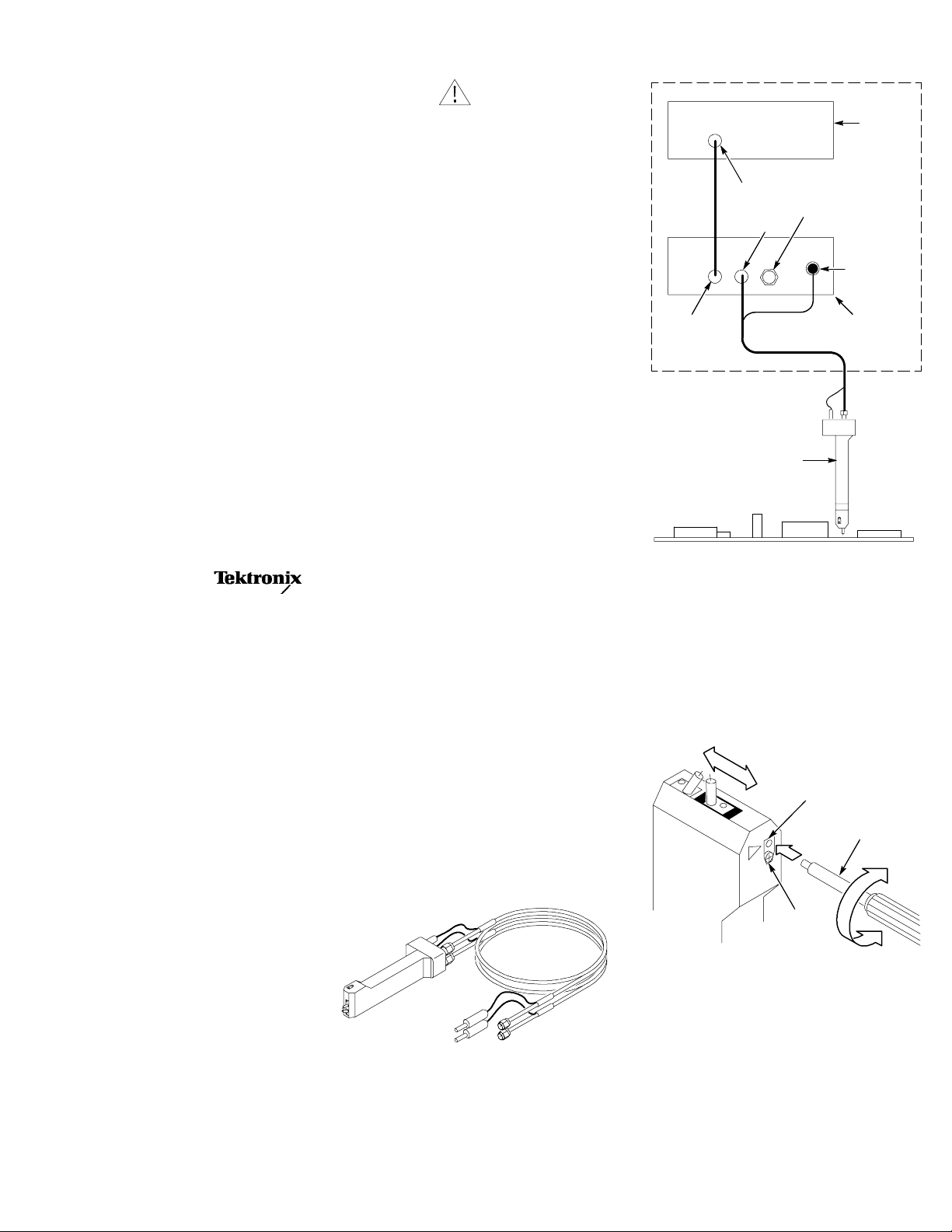
Connecting the Probe
P80318
Handheld Differential
Impedance Probe
Instructions
www.tektronix.com
*P071177501*
071-1775-01
Safety Summary
To avoid potential hazards, use this product only
as specified.
To avoid fire or personal injury
Ground the product. This product is indirectly
grounded through the grounding conductor of
the mainframe power cord. To avoid electric
shock, the grounding conductor must be connected to earth ground. Before making connections to the input or output terminals of the
product, ensure that the product is properly
grounded.
Connect and disconnect properly. Do not connect
or disconnect probes or test leads while they are
connected to a voltage source.
Observe all terminal ratings. To avoid fire or shock
hazard, observe all ratings and markings on the
product. Consult the host instrument documentation for further ratings information before making connections to the host instrument.
Do not apply a potential to any terminal,
including the common terminal, that exceeds the
maximum rating of that terminal.
Do not operate with suspected failures. If you
suspect there is damage to this product, have it
inspected by qualified service personnel.
Do not operate in wet/damp conditions.
Do not operate in an explosive atmosphere.
Keep product surfaces clean and dry.
Copyright E Tektronix. All rights reserved.
CAUTION
Refer to Product Manual
Product End-of-Life Handling. Observe the following guidelines when recycling an instrument
or component:
Equipment Recycling. This product complies
with the European Union’s requirements according to Directive 2002/96/EC on waste electrical
and electronic equipment (WEEE). For information about recycling options, check the Support/
Service section of the Tektronix Web site
(www.tektronix.com).
Restriction of Hazardous Substances. This
product has been classified as Monitoring and
Control equipment, and is outside the scope of
the 2002/95/EC RoHS Directive. This product is
known to contain lead and hexavalent chromium.
Warranty Information
For warranty information, go to
www.tektronix.com, click Support, and then
select Look Up Tektronix Warranty.
Probe tips and the ground wires are consumable
items and are not covered by the warranty.
Standard Accessories
The P80318 probe includes the following items:
H 2 one-meter SMA cables, each
with a parallel control line
H 3 ground wires (1 installed, 2 spares)
H Adjustment tool
H Vinyl probe tip protection cap
H 2 strap sets for fastening together the cables.
Product Description
The P80318 High Performance 100 Ohm
Differential Impedance Hand Probe provides
users a differential hand probe with adjustable
spacing tips, EOS/ESD protection (with the
Tektronix 80A02 EOS/ESD Protection Module),
and a unique double spring mechanism that
provides physical feedback to optimize probing
contact pressure. The probe is suitable for
probing differential runs on circuit boards, IC
package pins, and other devices that have a
0.5 mm to 4 mm pitch.
The P80318 probe is designed to be used with
the Tektronix 80A02 EOS/ESD Protection
Module. Together, they protect sensitive
instrument-input stages, such as the sampling
bridge of Tektronix electrical sampling modules,
from electro-overstress (EOS) and electrostatic
discharge (ESD) damage due to static charges
stored in the device under test (DUT).
Sampling
module
Input
Input
Output
Repeat for second cable
P80318 probe
DUT
50 Ω
termination
Control
80A02 Module
Connector Care
Use extra care when attaching or removing the
cable SMA connectors from the probe. Turn only
the nut, not the cable. When attaching the cable,
align the connectors carefully before turning the
nut. Use light finger pressure to make this initial
connection. Then tighten the nut lightly with a
wrench. Ideally, tighten the SMA connectors to
56 N-cm (5 in-lb) with a torque wrench.
Adjusting Probe Tip Gap
Adjustment hole
Adjustment tool
Adjustment
tension
Probing Guidelines
H The P80318 uses a unique double spring
mechanism that provides physical feedback
to optimize probing contact pressure. When
applying pressure after the initial contact to
the DUT, the first spring engages and the
probe tips retract with the first spring pressure. As you apply more pressure, the second
spring engages, increasing the probe compression resistance. This sudden increase in
stiffness is the correct operation zone. In-
Page 2

creasing pressure beyond this point accelerates probe tip wear and is not recommended.
Optimum probe tip
pressure
Probe tip pressure
Probe tip travel
H When the probe engages the second spring,
the probe sends a control signal to the 80A02
EOS/ESD protection module to enable the
signal path.
H Do not scrape or otherwise drag the probe
tips on the board traces or DUT leads in an
attempt to improve signal contact. Make
sure that the contact area is clean before
using the probe.
H Do not bend or shape the ground wire.
Improper bending of the wire can reduce
signal acquisition bandwidth or accuracy.
H Cover the probe tip when not in use with the
vinyl probe cover.
H When using the P80318 probe with auto-
mated probing stations, do not exceed
0.040 inches travel from initial DUT contact.
Removing/Installing the Ground Wire
Step 1
Set probe tips to maximum gap
Useknifetiptolift
end of wire
Step
2
Pull out old
wire with
tweezers
Step 3
Use tweezers to hold the new
wire. Insert the wire end ~1/3
length into the small hole
Step 4
1
Apply light pressure
against the wire to
keep in position
2
Pivot wire to position it on top of the support block.
Then use flat blade end of adjustment tool to push
wire down between block and probe tip.
Step 5
Push end of wire down
into hole. Insert screw
after wire is positioned
Ground wire is under tension during
installation and can easily spring away
Clamping the Probe for Fixtured Probing
Clamp
zone
Specifications
Table 1: Electrical
Characteristic
Probe impedance
Probe delay 1 ns typical from the female
Attenuation 1X
Risetime, probe head
and cable
Bandwidth, probe head
and cable, calculated
Maximum voltage input
RF input connector Precision 26 GHz SMA female
Control signal connector
type
Table 2: Environmental mechanics
Characteristic
Probe dimensions
Length 127.0 mm (5.0 in)
Height 33.0 mm (1.30 in)
Width 28.0 mm (1.10 in)
Weight (probe only) 0.075 kg (0.165 lbs)
Altitude
Operating 3,000 m (9,843 ft)
Non-operating 12,190 m (40,000 ft)
Ambient temperature
Operating --15 _C to +55 _C
Non-operating -- 6 2 _C to +85 _C
Humidity
Operating 20% to 80% relative humidity
Specification
50 Ω ±1.5 Ω, single ended,
each polarity.
SMA connector end to the
probe tip.
19.4 ps or better, one-way
transit, differential drive, with
minimum probe tip spacing (for
a 100 ps window with 50%
threshold crossing at center of
screen).
18 GHz or better, using above
risetime calculation and
assuming 0.35 product of
risetime and bandwidth.
±5.0 V (DC + AC
connector
Audio mono phone mini-jack
Specification
(+5 _F to +131 _F)
(--80 _F to +185 _F)
with a maximum wet bulb
temperature of +29 _Cator
below +40 _C,
non-condensing. (Upper limit
derates to 45% relative
humidity at +40 _C.)
p-- p
)
 Loading...