

Page 1
P77DESKEW Fixture Instructions
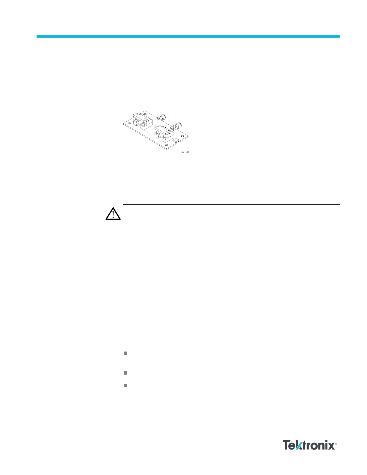
The P77DESKEW probe deskew fixture provides an edge source to time-align
(deskew) signals at the inputs of P7700 Series probes. The fixture provides a
means to desk
powered by one of the USB ports of the oscilloscope; a USB cable (Tektronix part
number, 174-6919-xx) is included with the fixture.
For performing the deskew procedure, Tektronix recommends using a
DPO/MSO70000C/70000DX series oscilloscope.
Connectors on the fixture accept solder tips that are available for the P7700 Series
probes. The fixture can also be used to deskew probes with browser accessories.
CAUTION. The probes used with the deskew fixture are ESD sensitive. To avoid
ing the probes, perform these procedures at an antistatic workstation, with
damag
an anti-static wrist strap while observing proper ESD practices. Refer to your
probe user manual for the anti-static information.
ew two probes at the same time. The probe and the fixture are
eck the calibration
Ch
www.tek.com
Copyright © Tektronix
status
For best performance, you should check the calibration status of the oscilloscope
before performing the deskew procedure. If the oscilloscope requires calibration
or the probe requires compensation, perform these steps before deskewing the
probes. Refer to your oscilloscope manual for instructions on performing the
oscilloscope calibration procedures.
To check the calibration status of the probe, perform the following steps:
1. Select Probe Cal... from the Vertical menu.
2. Select the channel to which the probe is attached and then check the Probe
Status readout. There are three possible values for the status:
Initialized. The probe has not been calibrated on the selected channel;
perform the DC probe calibration procedure.
Compensated. The probe has been calibrated on the selected channel.
Fail. The probe has not been calibrated; repeat the procedure.
If the test continues to fail, troubleshoot the problem; do not continue with the
deskew procedure.
*P077126300*
077-1263-00
Page 2
P77DESKEW Fixture Instructions
Deskew procedure
The deskew func
tion compensates for signal delays that occur between probes
due to different tips or cable lengths. The oscilloscope deskew feature applies
deskew values after it completes each acquisition. The deskew values do not
affect logic triggering.
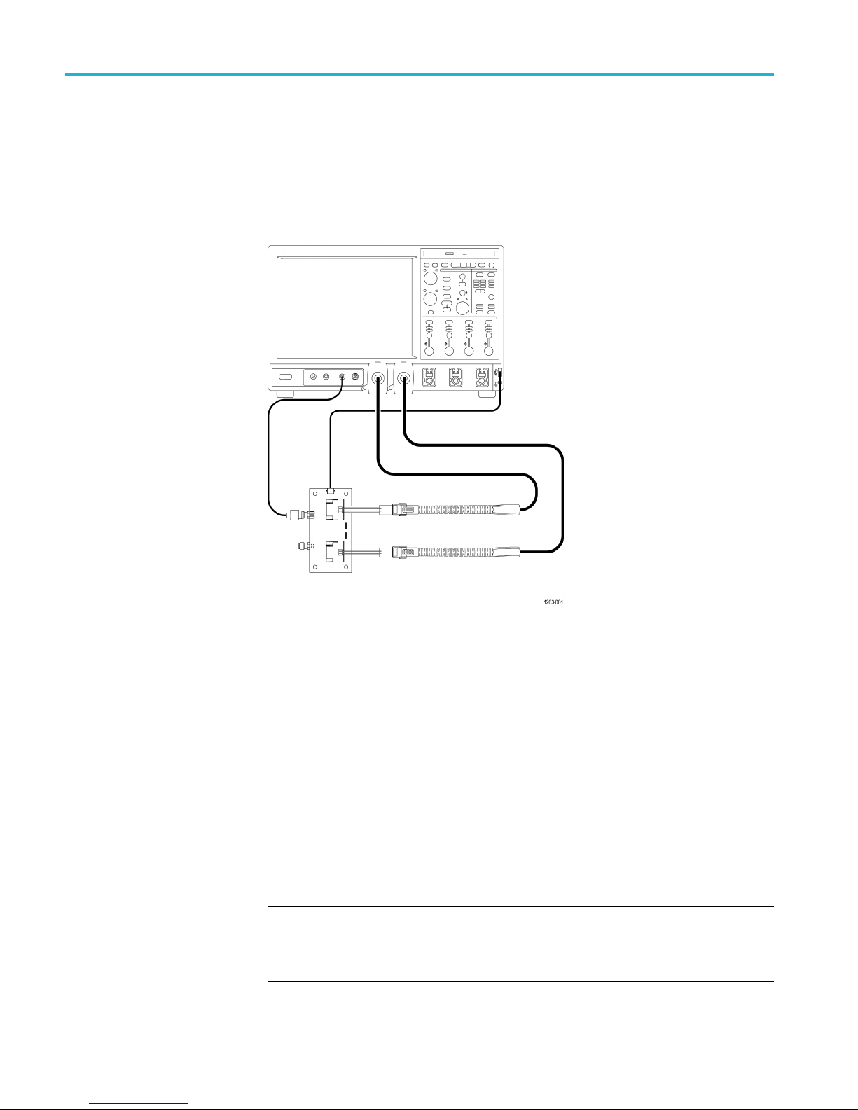
Refer to the following illustration while connecting the probes and cables to the
deskew fixture.
Figure 1: Connection diagram
1. Connect the deskew fixture to a USB power source, such as the front panel
USB connector on the oscilloscope. The LEDs on the fixture will turn on.
2. Connect the probes to oscilloscope channels where they will be used.
3. Connect the TekFlex tips to the ends of the main probe cables.
4. For single-ended inputs, connect an SMA cable from a single source, such as
the FAST EDGE output connector on the oscilloscope to the A input of the
fixture.
5. If using a signal generator with differential inputs, connect the + output of
the signal generator to the A input of the fixture using an SMA cable. Then
connect the - output of the signal generator to the B input of the fixture using
an SMA-style cable with equal electrical length as the first SMA cable.
NOTE. If you are deskewing probes with solder tips, try to use the same solder
tips with the deskew fixture that you will use to take measurements. If that is not
possible, try to use a solder tip of similar length to the one you have soldered to
your device.
2 P77DESKEW Fixture Instructions
Page 3
P77DESKEW Fixture Instructions
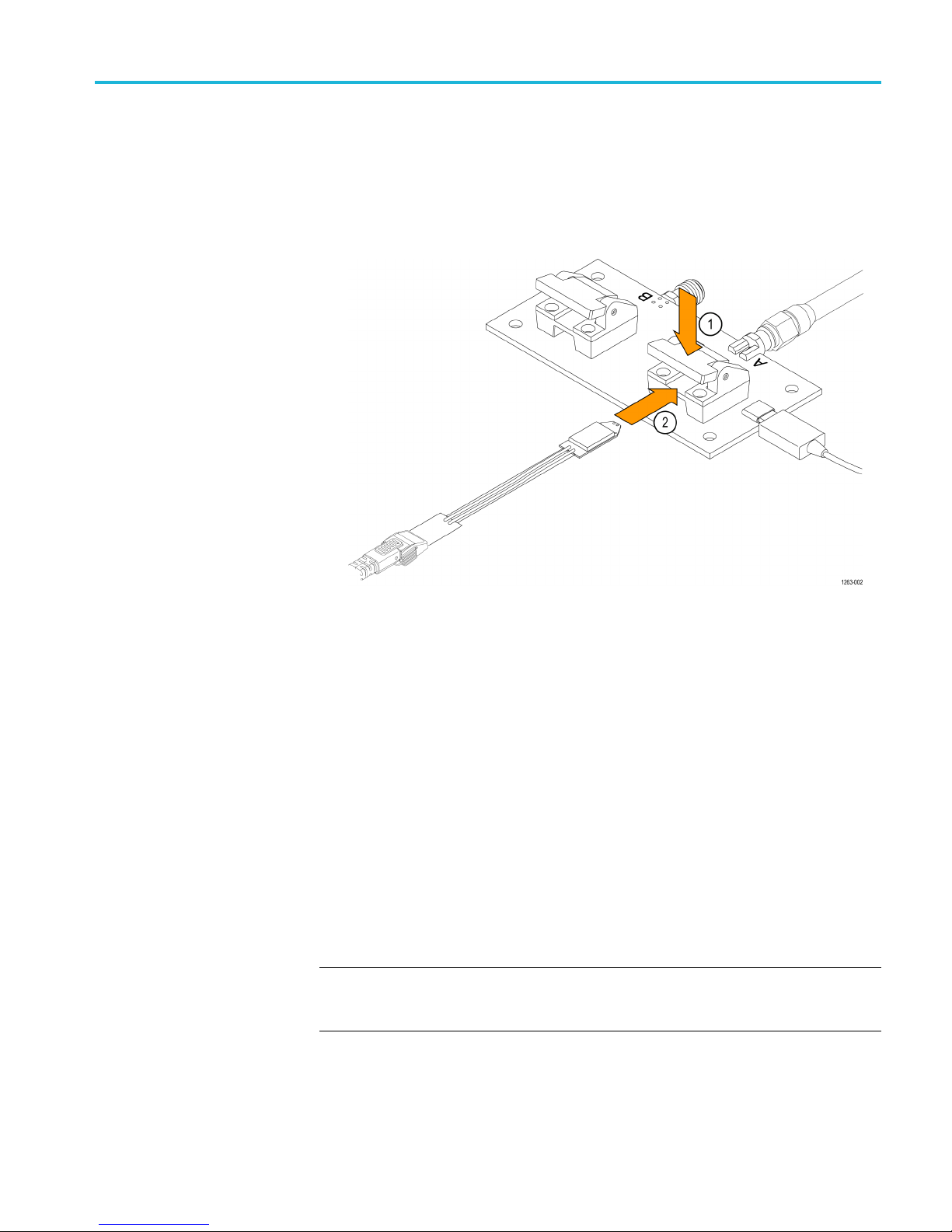
6. For P77STFLXA o
follows:
a. Locate the Por
spring-loaded clamp. Insert one of the probe tips in the direction shown in
the following figure, and release the clamp so that the tip locks in place.
r P77STCABL tips, connect the tips to the fixture as
t1 plastic clamp on the fixture and press down on the
Figure 2: Connecting the probe tip to the deskew fixture
A green LED lights up under the probe tip clamp when the tip is properly
inserted.
b. Repeat the above step for inserting the second probe tip into the Port2
plastic clamp.
c. Verify that the green LEDs under both probe tips are on. If not,
double-check your connections.
7. For P77BRWSR browser accessory, there are several pads on the deskew
fixture that can be contacted by the browser tips. Using these pads, two probes
th browser accessories or one probe with a solder tip and one probe with a
wi
browser can be deskewed relative to one another.
he pads on the fixture provide access to the same signals routed t o the
T
clamps used to connect the solder tips. There are also ground pads located in
the same area for use when deskewing using a single-ended signal.
NOTE. The s ignals routed to the pads are delayed by 30 ps relative to the signal
output at the solder tip clamps. There is a 5.7 ps time difference between the
first row of pads and the second row.
P77DESKEW Fixture Instructions 3
Page 4

P77DESKEW Fixture Instructions
Insert the TekF
lex connectors into the P77BRWSR tips and then continue
with the following steps:
a. Press one of th
e P77BRWSR tips against one of the pairs of signal traces
on the B (Port4) side of fixture board edge, located between the Port1 and
Port2 clamps. Press the second tip against one of the ground pads on the
right side of the row.
4 P77DESKEW Fixture Instructions
Figure 3: Connection points for the P77BRWSR tips on the deskew fixture
b. Press the second P77BRWSR tip against a second pair of signa l traces on
the A (Port3) side of the fixture and one of the ground pads.
Page 5

P77DESKEW Fixture Instructions
The following fi
gure shows an example of using the hands-free accessories
with two browsers connected to the deskew fixture.
Figure 4: Connecting the hands-free accessories and P77BRWSR to the deskew
fixture
8. Adjust the oscilloscope to display a stable waveform or push the Autoset
n. Choose a channel to use as the reference channel. Channel 1 works
butto
well for this purpose.
9. Sele
ct Deskew from the Vertical menu.
10. Select the reference channel button and se t the Deskew to 0.0 s.
11. Set the acquisition mode on the oscilloscope to average.
12. Adjust the trigger level to get a stable trigger.
13. Turn on the display of the second oscilloscope channel.
14. Adjust the vertical SCALE, POSITION, and OFFSET for each channel so
that signals from the reference and second channel overlap and are centered
on screen.
P77DESKEW Fixture Instructions 5
Page 6

P77DESKEW Fixture Instructions
15. Adjust the hori
zontal SCALE and horizontal POSITION so the differences in
the channel delays are clearly visible. The waveforms on the screen should
look similar to the following figure (note the delay between the two edges):
Figure 5: Signal delay between two channels
16. Select Deskew from the Vertical menu.
17. Select the button for the second channel that will be matched in time to the
reference channel.
NOTE. Do the next step at a signal amplitude within the same attenuator range
(vertical scale) as your planned signal measurements. On the MSO/DPO70000C
series oscilloscope, a change to the vertical scale (Attenuator Setting) can cause
o 100 ps variation in timing skew between channels. If you are using an
up t
MSO/DPO70000D/DX series oscilloscope, the channel-to-channel skew will not
change with a vertical scale change.
6 P77DESKEW Fixture Instructions
Page 7

P77DESKEW Fixture Instructions
18. Adjust the desk
ew time for that channel so that its signal aligns with that of
the reference channel. When the signals are aligned they should look similar
to the following figure:
Figure 6: Aligned signals, no delay
19. Repeat the preceding steps for each additional channel that you want to
deskew.
P77DESKEW Fixture Instructions 7
Page 8

P77DESKEW Fixture Instructions
P77DESKEW
specifications
Description Specification
Input impedance
Fast Edge signal A&Binput connectors SMA
Maximum input signal 4.6 V
Time delay (Typical)
A to B (differential signal path)
Port1 to Po
Port1 to Port3 or to Port4 30 ps
Port2 to Port3 or to Port4 30 ps
Difference between two rows of pads
Tempera
Operati
Non-operating
rt2, or Port3 to Port4
ture
ng
50 Ω ±2%
RMS
≤5ps
≤10 ps
5.7 ps
0°Cto+4
-20°C t
5 °C (32 °F to +113 °F)
o+60°C(-4°Fto+140°F)
NOTE. The s ignals routed to the pads are delayed by 30 ps relative to the signal
output at the solder tip clamps. There is a 5.7 ps time difference between the
first row of pads and the second row.
Environmental information
Contacting Tektronix
Warranty information
Equipment Recycling. This product complies with the European
Union’s requirements according to Directive 2002/96/EC on waste
electrical and electronic equipment (WEEE). For more information
about recycling options, check the Support/Service section of the
Tektronix Web site (www.tektronix.com).
Web site: www.tek.com
Phone: 1-800-833-9200
Ad
E
dress:
mail:
ktronix, Inc.
Te
Department or name (if known)
14200 SW Karl Braun Drive
O. Box 500
P.
Beaverton, OR 97077 USA
techsupport@tek.com
For warranty information, go to www.tek.com/warranty.
8 P77DESKEW Fixture Instructions
 Loading...