

Page 1
Final Review Copy * 7.16.2013
P7600 Series P
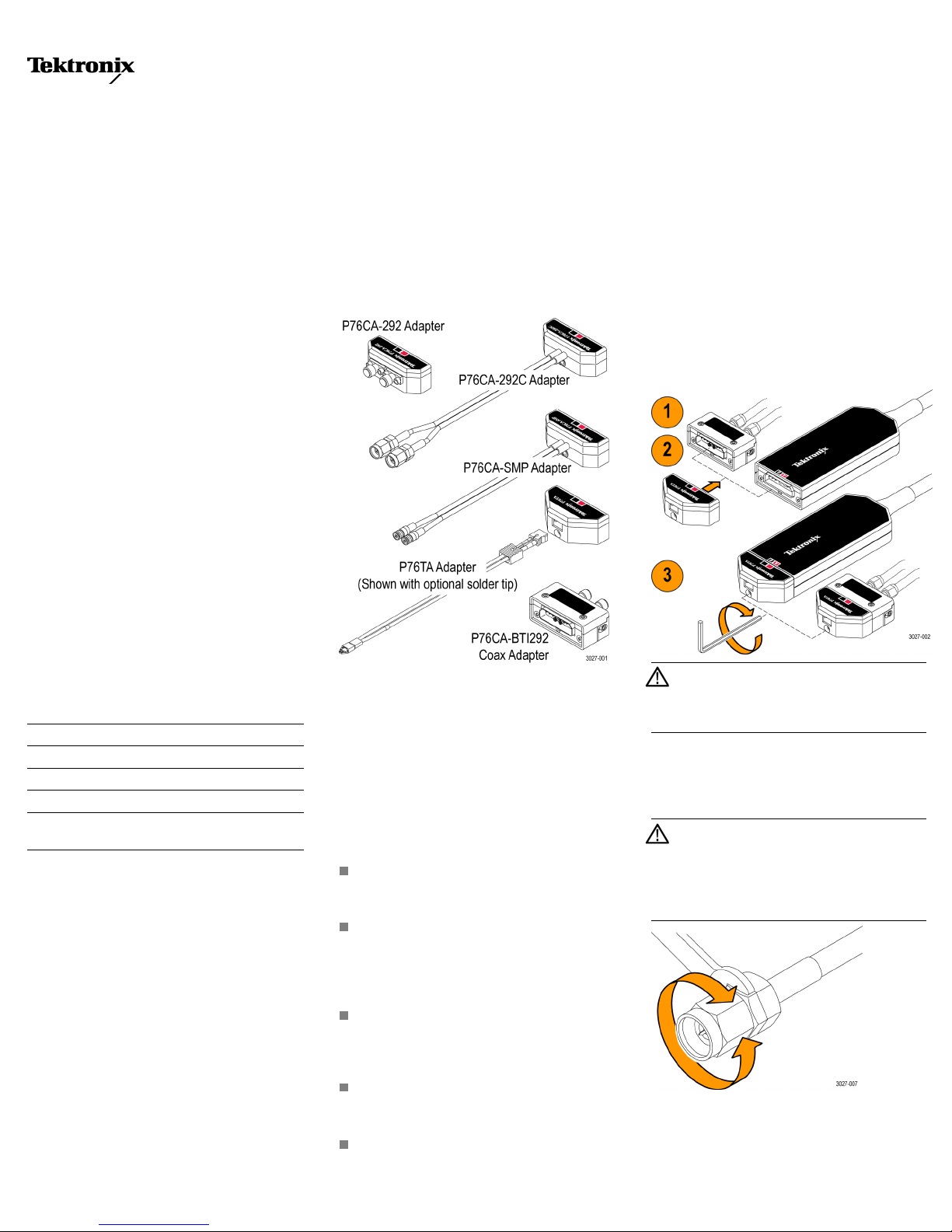
Adapters
ZZZ
Instructions
robes
cables should be
high-quality connectors at both ends.
The P76TA Solder Tip A dapter allows you to
connect to P7500 Series TriMode solder-down
tips; for example, the P75PST Performance
Solder Tip.
The P76CA-BTI292 Coax Adapter allows
the conversion of the P76TA or P76CA
adapters’ Buffered Tip Interface to a pair of
2.92 mm connectors. Using this adapter, the
distance between the circuit under test and the
oscilloscope can be extended. High bandwidth,
low skew cable pairs should be used for this
extended reach.
short (<6 in /152 mm) and have
let the weight of
the coax connectors if the probe is hanging
vertically off o
the probe head pull on
f the circuit.
Connection Procedures
Connect the adapter to the probe head or
P76CA-BTI292 Coax Adapter, and then connect
the cable or use the solder-down procedure for
your circuit connection. These procedures are
described in detail below.
Adapter to Probe Head or P76CA-BTI292
1. Align the adapter to the probe head or the
P76CA-BTI292 adapter.
2. Push the adapter in until it seats against the
probe head or adapter.
3. Use the 2 mm hex wrench to tighten the
screw on the adapter.
*P071302701*
071-3027-01
Overview
These instructions apply to the adapters below:
Adapter Description
P76CA-292 2.92 mm Coax Adapter
P76CA-292C 2.92 mm Coax Adapter with Cables
P76CA-SMP SMP Coax Adapter with Cables
P76TA
P76CA-BTI292 P7600 Custom Tip Interface Coax
1
Requires a matched-pair coaxial cable set
2
Requires a P7500 Series TriMode solder tip
P7500 Series Solder Tip Adapter
1
Adapter
Accessories
All of the adapters include these instructions and
a 2 mm hex wrench for securing the adapter to
the probe head. The P76TA adapter also includes
a kit of solder ramps to help minimize the solder
tip lead lengths for best performance.
Description
The coax adapters are designed to complete the
connection from Tektronix P7600 Series probes
to SMP and SMA connectors on your circuit. The
coax adapters support full TriMode capability
(differential, single-ended, and common-mode
configurations).
Use the P76CA -292 Coax Adapter with high
bandwidth, low skew (<2 ps) cable pairs. The
1
2
Using the Adapters
The probe and probe adapters are extremely
sensitive to electrostatic discharge (ESD).
Always work at an ESD-approved workstation or
in an ESD-approved environment.
Secure mechanical connections are necessary
to ensure the best signal integrity between the
adapters, the probe and the circuit under test.
Therefore, always observe the best practices
listed below for the best performance.
Use the 2 mm hex wrench included w ith the
adapters to tighten the screw on the adapter
housing to the probe head.
After you hand-tighten the coax connectors
to your circuit, use two wrenches to secure
each connector: One on the middle cable
nut to minimize cable twist, and a torque
wrench on the connector.
When you tighten cable connectors that are
close to each other (as on the P76CA-292
adapter), be careful not to strike adjacent
connectors with the wrench.
To preserve the adapter cables and maintain
the highest signal fidelity, never kink the
wires or put undue stress on them.
Secure the probe and probe adapter to the
circuit or chassis to prevent excessive strain
on the connections. For example, do not
CAUTION. To prevent over-torquing the
screw, only insert the long end of the wrench
into the screw. The probe head can be
damaged by over-torquing the screw.
Coax Adapters
To prevent damage a nd prolong connector and
cable life, the cable and center conductors must
not twist when making connections.
CAUTION. Always use a wrench to minimize
the cable twist when you connect and
disconnect the 2.92 mm adapters and cables.
Use a torque wrench to tighten the c onnectors
to 8 in-lbs. Failure to do so will shorten the
service life of the adapters.
Coaxial cables can store a static charge when
they are not connected to equipment or circuitry,
so you should briefly short the center conductor
of the cable to the outer conductor before
Page 2
Final Review Copy * 7.16.2013
connecting the c
able to the adapters or your
circuit.
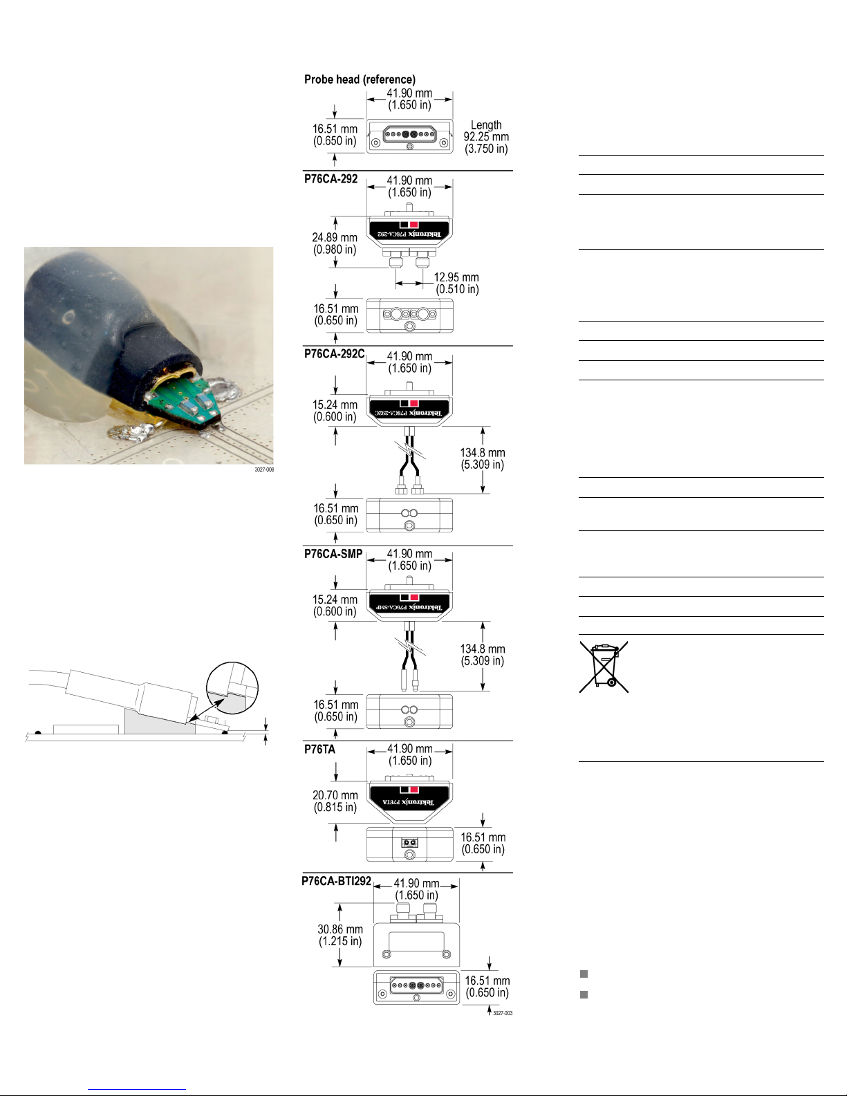
P7500SeriesSolderTips
1. Choose a location where the solder
tip c an reach your test points, while
keeping the tip leads as short as possible
(<0.032 in./0.8 mm). The solder ramps
included with the P76TA adapter help to
achieve this, as shown in the photo below.
Note signal polarities and grounds where
applicable.
Dimensions Electrical Char
The specifications in the table below apply
to the P7633 prob
MSO/DPO73304D/DX oscilloscope.
P7600 Series TriMode Coax Adapters
P76CA-292 P76CA-292C P76CA-SMP
Bandwidth 33 GHz 33 GHz 33 GHz
1
Rise time
10–90%
20–80%
1
Temperature range +18 °C to +28 °C (64 °F to 82 °F)
14 ps
11 ps
P76TA Adapter + P75PST Tip + P7633/P7630 Probe
or P76CA-BTI292 Adapter
Bandwidth 30 GHz
Rise time, 10–90% 16 ps
Rise time, 20–80% 12 ps
Optional Accessories
The following accessories are available for the
adapters and tips.
acteristics (Typical)
ewhenusedwitha
14 ps
11 ps
14 ps
11 ps
2. Apply solder to the test points on your
circuit, and then solder wires to the test
points. Use 4 to 8 mil wire for best results.
A wire kit that also includes lead-free solder
is available; see Optional Accessories.
3. Attach the
solder ramp to the tip: Align the
bottom of the tip to the notch in the ramp
as shown, a
nd then secure the tip to the
ramp with glue or tape. The notch in the
ramp helps
you to position the tip as close
as possible to the circuit connections.
4. Slide the tip over the soldered wires on your
circuit and solder the wires to the tip. Clip
off any excess wires.
5. Secure t
he tip to your circuit with tape or
hot glue.
6. Align the solder tip cable with the red band
to the red A input of the probe adapter. Push
the cable into the probe adapter until it seats
in the adapter.
7. For a secure mechanical connection, use
tape or hot glue to secure the adapter and
probe head to your circuit.
30 GHz Performance Solder Tip P75PST
20 GHz TriMode Solder Tip P75TLRST
P7500 Series TriMode Solder Tip
solderramps(kitof25)
Replacement wire kit
(includes one roll each of: 4 mil wire,
8 mil wire, SAC305 lead-free solder)
Phase-matched SMA cables (38 in.)
Adapter wrench, 2 mm (1 each)
Equipment Recycling. This product
complies with the European Union’s
requirements according to Directive
2002/96/EC on waste electrical and
electronic equipment (WEEE). For
more information about recycling
options, check the Support/Service
section of the Tektronix Web site
(www.tektronix.com).
020-3118-xx
020-2754-xx
174-5771-xx
129-2781-xx
Warranty Information
For warranty information, go to
www.tektronix.com\warranty.
Contacting Tektronix
Tektronix, Inc.
14200 SW Karl Braun Drive
PO Box 500
Beaverton, OR 97077
USA
For product information, sales, service, and
technical support:
In North America, call 1-800-833-9200.
Worldwide, visit www.tektronix.com to find
ontacts in your area.
c
opyright © Tektronix, Inc. All rights reserved. www.tektronix.com
C
 Loading...