

Tektronix P7630, P7625, P7633 Field Install Instructions

x
P7600 Series
TriMode™ Probes
ZZZ
User Manual
*P071302602*
071-3026-02


xx
P7600 Series
TriMode™ Probes
ZZZ
User Manual
www.tek.com
071-3026-02

Copyright © Tektronix. All rights reserved. Licens ed software products are owned by Tektronix or its subsidiaries or suppliers, and are protected by
national copyright laws and international treaty provisions.
Tektronix products are covered by U.S. and foreign patents, issued and pending. Information in this publication supersedes that in all previously
published material. Specifications and price ch ange privileges reserved.
TEKTRONIX and TEK are registered trademarks of Tektronix, Inc.
EZ-Probe is a registered trademark of Cascade Microtech, Inc.
TriMode is a trademark of Tektronix, Inc.
Contacting Tektronix
Tektronix, Inc.
14150 SW Karl Braun Drive
P.O . B ox 5 0 0
Beaverton, OR 97077
USA
For product information, sales, service, and technical support:
In North America, call 1-800-833-9200.
Worldwide, visit www.tek.com to find contacts in your area.

Warranty
Tektronix warrants that this product will be free from defects in materials and workmanship for a period of one (1) year from the date of shipment. If
any such product proves d efective during this warranty period, Tektronix, at its option, either will repair the defective product without charge for parts
and labor, or will provide a replacement in exchange for the defective product. Parts, modules and replacement products used by Tektronix for
warranty work may be new or reconditioned to like new performance. All replaced parts, modules and products become the property of Tektronix.
In order to obtain service under this warranty, Customer must notify Tektronix of the defect before the expiration of the warranty period and make
suitable arrangements for the performance of service. Customer shall be responsible for packag ing and shipping the defective product to the service
center designated by Tektronix, with shipping charges prepaid. Tektronix shall pay for the return of the product to Customer if the shipment is to a
location within the country in which the Tektronix service center is l o cated. Customer shall be responsible for paying all shipping charges, duties,
taxes, and any other charges for products returned t o any other locations.
This warranty shall not apply to any defect, failure or da m age caused b y improper use or improper or inadequate maintenance and care. Tektronix
shall not be obligated to furnish service under this warranty a) to repair damage resulting from attempts by personnel other than Tektronix
representatives to install, repair or service the product; b) to repair damage resulting from improper use or connection to incompatible equipment; c) to
repair any damage or malfunction caused by the use of non-Tektronix supplies; or d) to s ervice a product that has been modified or integrated with
other products when the effect of such modification or integration increases the time or difficulty of servicing the product.
THIS WARRANTY IS GIVEN BY TEKTRONIX WITH RESPECT TO THE PRODUCT IN LIEU OF ANY OTHER WARRANTIES, EXPRESS OR
IMPLIED. TEK TRONIX AND ITS VENDORS DISCLAIM ANY IMPLIED WARRANTIES OF MERCHANTABILITY OR FITNESS FOR A PARTICULAR
PURPOSE. TEKTRONIX' RESPONSIBILITY TO REPAIR OR REPLACE DEFECTIVE PRODUCTS IS THE SOLE AND EXCLUSIVE REMEDY
PROVIDED TO THE CUSTOMER FOR BREACH OF THIS WARRANTY. TEKTRONIX AND ITS VENDORS WILL NOT BE LIABLE FOR ANY
INDIRECT, SPECIAL, INCIDENTAL, OR CONSEQUENTIAL DAMAGES IRRESPECTIVE OF WHETHER TEKTRONIX OR THE VENDOR HAS
ADVANCE NOTICE OF THE POSSIBILITY OF SUCH DAMAGES.
[W2 – 15AUG04]


Table of Contents
General safety summary .. . ................................................................................................................ iii
Environmental Considerations .............................................................................................................. v
Preface...................................................................................................................................... vi
Probe Models ......................................................................................................................... vi
Documentation........................................................................................................................ vi
Key Features ............................................................................................................................... 1
Operating Considerations .................................................................................................................. 2
Installation .................................................................................................................................. 3
Overview .............................................................................................................................. 3
Connect TriMode Adapters to the Probe Body. ...................................................................................... 4
Connect to the Host Instrument . . . ................................................................................................... 6
Control Box Controls and Indicators.................................................................................................. 8
Functional Check and Calibration......................................................................................................... 11
Functional Check .................................................................................................................... 11
TriMode Probe DC Calibration.......................................................................................................15
Basic Operation............................................................................................................................ 20
Probe Setup Screen ................................................................................................................. 25
Selecting theProbe Tip .............................................................................................................. 33
Improving Measurement Accuracy .................................................................................................. 34
Table of Contents
P7600 Series TriMode Probes User Manual i

Table of Contents
Accessories and Options.................................................................................................................. 49
Maintenance ............................................................................................................................... 61
Index
Connecting to a Circuit Board . . ..................................................................................................... 39
Standard Accessories . .............................................................................................................. 49
Optional Accessories ................................................................................................................ 53
Options............................................................................................................................... 60
Host Instrument Firmware ........................................................................................................... 61
Error Conditions...................................................................................................................... 62
User-Replaceable Parts ............................................................................................................. 64
Handling the Probe .................................................................................................................. 68
Cleaning the Probe .................................................................................................................. 69
Returning the Probe for Servicing...................................................................................................70
ii P7600 Series TriMode Probes User Manual

General safety summary
Review the following safety precautions to avoid injury and prevent damage to this product or any products connected to it.
To avoid potential hazards, use this product only as specified.
Only qualified personnel should pe rform service procedures.
To avoid fire or personal injury
Connect and disconnect properly. Connect th e probe output to the measurement instrument before connecting the probe to the
circuit under test. C onnect the probe reference lead to the circuit under test before connecting the probe input. Disconnect the probe
input and th e probe reference lead from the circuit under test before d isconnecting the probe from the measurement instrument.
Observe all terminal ratings. To avoid fire or shock hazard, observe all ratings and markings on the product. Consult the product
manual for further ratings information before making connections to the product.
Do not ap ply a potential to any terminal, including the c ommon terminal, that exceeds the maximum rating of that terminal.
Do not operate without covers. Do not operate this product with covers or panels removed.
Do not operate with suspected failures. If you suspect that there is damage to this product, have it inspected by qualified
service personnel.
Avoid exposed circuitry. Do not touch exposed connections and components when power is present.
Do not operate in wet/d amp conditions.
General safety summary
Do not operate in an explosive atmosphere.
Keep product surfaces clean and dry.
P7600 Series TriMode Probes User Manual iii
General safety summary
Termsinthismanual
These terms may appear in this manual:
WARNING. Warning statements identify conditions or practices that could result in injury or loss of life.
CAUTION. Caution statements identify conditions or practices that could result in damage to t his product or other property.
Symbols and terms on the product
These terms may appear on the product:
DANGER indicates an injury hazard immediately accessible as you read the marking.
WARNING indicates an injury hazard not immediately accessible as you read the marking.
CAUTION indicates a hazard to property including the product.
The following symbol(s) may appear on the product:
iv P7600 Series TriMode Pro bes User Manual

Environmental Considerations
This section provides information about the environmental impact of the product.
Product End-of-Life Handling
Observe the following guidelines when recycling an instrument or component:
Equipment Recycling. Production of this eq uipment required the extraction and use of natural resources. The equipment may
contain substances that could be harmful to the environm ent or human health if improperly handled at the product’s end of life. In
order to avoid release of such substances into the environment and to reduce the use of natural resources, we encourage you to
recycle this product in an appropriate system that will ensure that most of the materials are reused or recycled appropriately.
This symbol indicates that this product complies with the applicable European Union requirements according to
Directives 2012/19/EU and 2006/66/EC on waste electrical and electronic equipment (WEEE) and batteries. For
information about recycling options, che ck the Tektronix Web site (www.tek.com/productrecycling).
Environmental Considerations
P7600 Series TriMode Probes User Manual v

Preface
Preface
This manual describes the installation and operation of the P7600 Series TriMode Probes. Basic p robe operations and
concepts are presented in this manual. All documents listed below are located on the Tektronix Web site for these documents
(www.tektronix.com/manuals).
Probe Models
The probe models covered in the P7600 Series TriMode Probes documentation are listed below.
P7625 25 GHz
P7633 33 GHz
Documentation
To read about Use these documen ts
Installation and operation (overviews) Read this quick start user manual for general information about how to use
In-depth operation
Specifications Use the technical reference manual.
Reordering accessories
your probe.
Use the technical reference manual along with the user manual.
Use the Accessories and Options section in this manual.
vi P7600 Series TriMode Probes User Manual
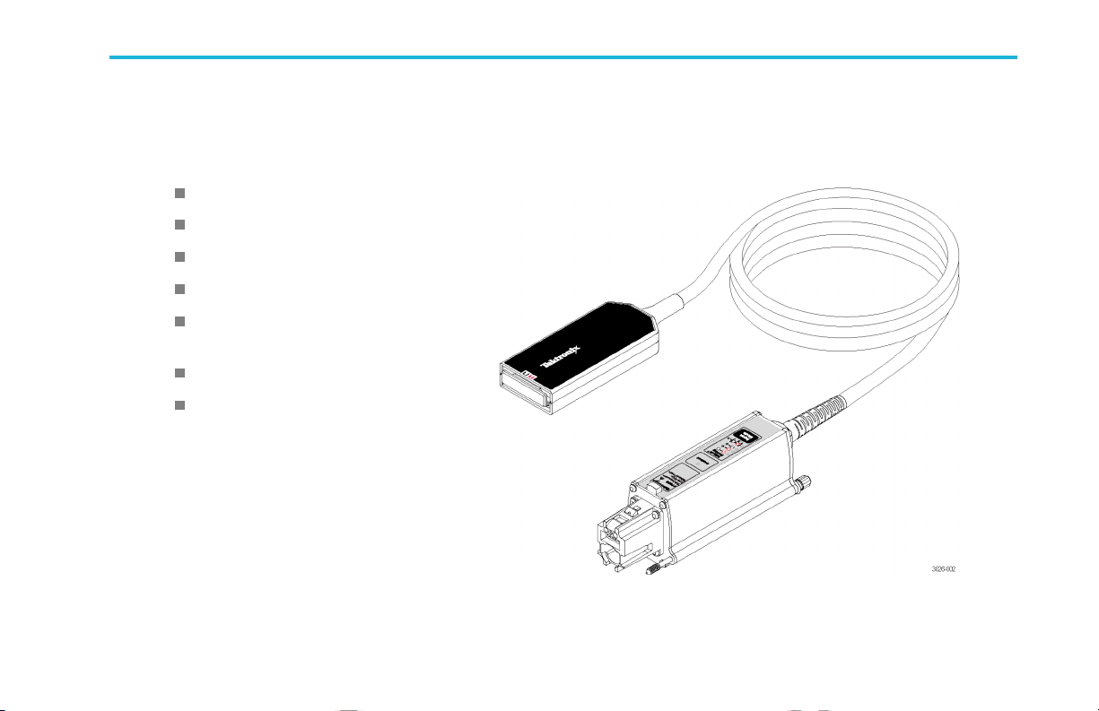
Key Features
The P7600 Series TriMode Probes allow you to take differential, single-ended, and common mode measurements with one probe
connection. Key features includ e:
Revolutionary TriMode operation
TekConnect interface
>33 GHz Bandwidth (typical, P7633)
14 ps Rise time 10-90% (typical, P7633)
Key Features
<1.1 mV
adapters
Automatic tip adapter type identification
DSP-corrected response provided for
improved measurement fidelity
P7600 Series TriMode Probes User Manual 1
System noise with P76CA-xxx
RMS

Operating Considerations
Operating Considerations
Table 1: P7600 Series TriMode Probes
Characteristic Description P76CA-xxx adapters P76TA adapter
Input voltage Dynamic range
Input voltage ran ge
(DC + peak AC, input referenced
to ground)
Maximum no ndestructive voltage ±5 V ±8 V
Temperature
Humidity
Altitude
Pollution degree 2, Indoor use only
CAUTION. To avoid ESD damage to the probe, always use an antistatic wrist strap (provided with your probe), and work at
a static-approved workstation when you handle the probe.
Operating
Nonoperating
Operating
Nonoperating
Operating
Nonoperating
1.2 V
2.0 V
(single-ended)
p-p
(differential)
p-p
6.0 V
10.0 V
(single-ended)
p-p
(differential)
p-p
+4.0 V, –4.0 V +5.0 V, –5.0 V
0 to +40 °C (+32 °F to +104 °F)
-20°Cto+60°C(-4°Fto+140°F)
Up to +40 °C (+104 °F) 20%-80% RH
+30 °C to +46 °C (+86 °F to +115 °F) 0-90% RH
3000 meters (9842 feet)
12000 meters (39,370 feet)
2 P7600 Series TriMode Probes User Manual
Installation
Before you connect the probe to your instrument, read the Overview below to understand the sequence of events necessary to
properly install the probe and adapters.
CAUTION. To avoid ESD damage to the probe, always use an antistatic wrist strap (provided with your probe), and work at
a static-approved workstation when you handle the probe.
Overview
1. Connect a P76xxx adapter to the probe. This step should be done before you connect the probe to the oscilloscope.
2. Connect the probe to the oscilloscope.
3. The probe performs a self test, and then one Input Mod e LED remains lit.
4. The oscilloscope discovers the probe (if this is the first time they are connected), and downloads S-parameter data from the
probe. The oscilloscope then computes the filters. A message displays until the process is complete.
5. The P robe Setup screen displays (if this is a first-time connection).
6. Perform a functional check on th e probe.
7. Use the Probe Setup screen to set the probe parameters as described in the Basic Operation section.
Installation
P7600 Series TriMode Probes User Manual 3
Installation
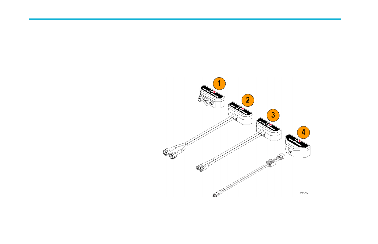
Connect TriMode Adapters to the Probe Body
TriMode adapters are required to complete the connection between the probe and your circuit, and are briefly de scribed below. The
adapters connect the P7600 Series probes to your circuit through 2.92 mm or SMP cables, or through P7500 Series solder tips,
such as the P75PST Performance Solder Tip. The adapter inputs are polarized, with the A input marked in red and the B input
marked in black. The adapters should be connected to the probe before the probe is connected to the instrument.
1. P76CA-292
Use this adapter with high quality,
skew-matched cables that have male
2.92 mm connectors at the probe end. The
other end of the cables can be customized with
connectors that mate to your circuit.
2. P76CA-292C
This adapter includes a pair of skew-matched,
6 inch cables with male 2.92 mm connectors.
3. P76CA-SMP
This adapter includes a pair of skew-matched,
6 inch cables with female SMP connectors.
4. P76TA
Use this adapter with P7500 Series probe
solder tips. (See page 39, Connecting to a
Circuit Board.)
4 P7600 Series TriMode Probes User Manual

Connect th e Adapters
All of the adapters mate to the P7600 Series
probe head through a keyed, multi-pin
connector that transfers the adapter information
to the oscilloscope for automatic identification.
Connect them as follows:
1. Orient the adapter to the probe body with
the A and B inputs on top, as shown.
2. Insert the adapter into the probe head.
3. Attach the adapter to the probe head with
the hex tool included with the probe. Use
the long end of the tool as shown, a nd only
use enough force to ensure a secure fit.
CAUTION. As you tighten the adapter screw,
be careful not to damage the input cables on
adapters with integral cables.
CAUTION. Do not overtighten the adapter
screw. You can damage the connectors if you
apply too much torque to the screw.
Installation
P7600 Series TriMode Probes User Manual 5
Installation
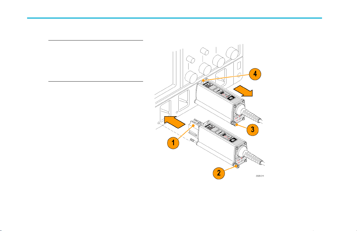
Connect to the Host Instrument
NOTE. Your TekConnect instrument may
require a firmware upgrade to support full
functionality of the P7600 Series probes.
Before you connect the probe, check the
version requirements. (See page 61, Host
Instrument Firmware.)
1. Slide the probe into the TekConnect
receptacle. The probe clicks into place
when fully engaged.
2. Turn the thumbscrew clockwise (finger-tight
only) to secure the probe to the instrument.
Disconnect
3. To disconnect, turn the thumbscrew
counter-clockwise.
4. Press the latch release button and pull the
probe away from the instrument.
6 P7600 Series TriMode Probes User Manual

Probe Power-On
After the initial connection to the oscilloscope
is made:
1. The probe briefly lights all LEDs during a
self-test, and then the A – B Input Mode
LED remains lit.
2. The probe transfers data to the host
instrument, and a message displays on the
instrument as the transfer occurs.
The data transfer takes a few minutes,
and is only done when the host instrument
discovers a new probe. The data transfer
only occurs on instruments that are fully
compatible with the probe.
3. After the data transfer is done, the probe is
ready for a functional check and calibration.
(See page 11, Functional Check.)
Installation
P7600 Series TriMode Probes User Manual 7

Installation
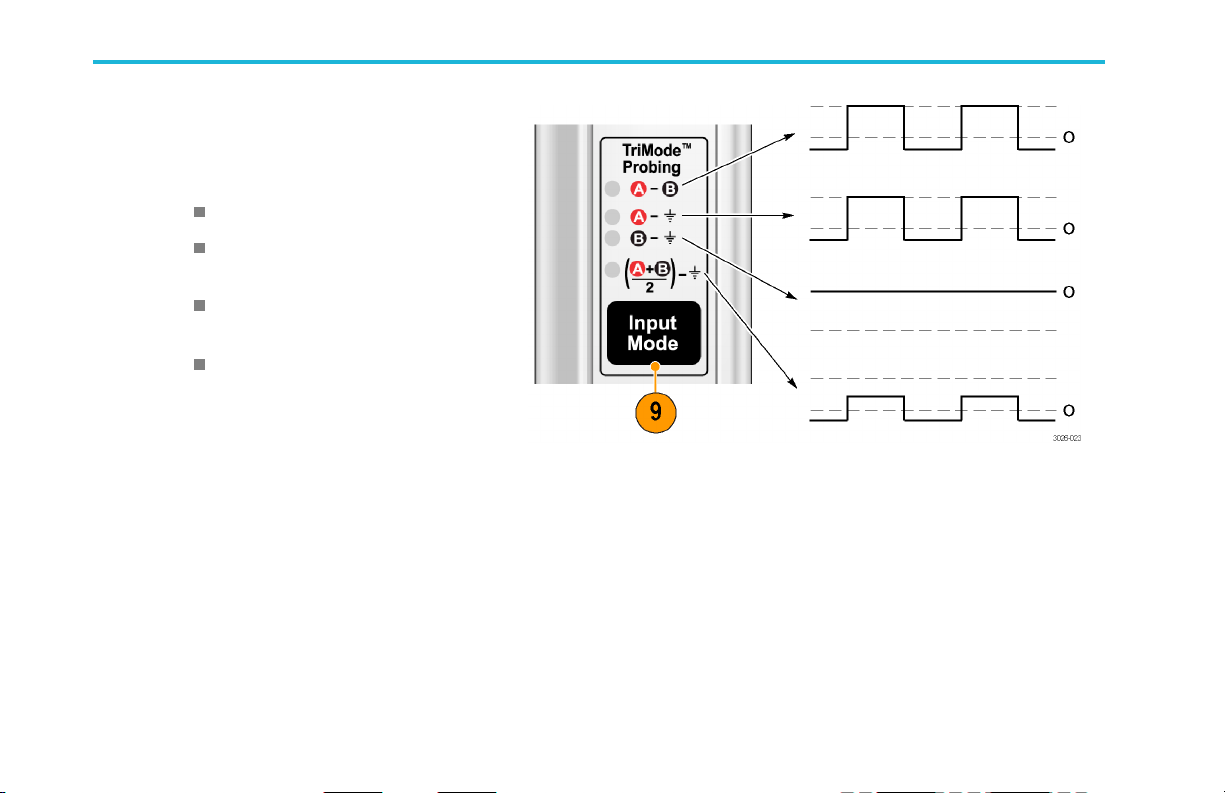
Control Box Controls and Indicators
Input Mode Button and LEDs
Press the Input Mode button to select one of
the four TriMode measurements. The modes
cycle in the following sequence:
A – B (for differential signal measurement)
A – GND (for A inp ut single-ended
measurement)
B – GND (for B inp ut single-ended
measurement)
(A+B)/2–GND(forcommonmode
measurement)
NOTE. You can also change the Input Mode
in the oscilloscope Probe Setup screen. (See
Figure 4 on page 25.)
8 P7600 Series TriMode Probes User Manual
Installation
Overload LED
The Overload LED glows amber under the
following conditions when using the P76CA-xxx
adapters:
• the input voltage on either the A or B input
exceeds ±4.5 V
• the termination voltage driver current on
the A or B input exceeds 50 mA
(See page 23, Termination Voltage.)
The Overload LED clears when the input sign al
is removed.
NOTE. The Overload LED may flash briefly
when you ad just the termination voltage levels;
this is normal.
CAUTION. Do not exceed the input voltage limits of the probe and adapters. The probe or oscilloscope circuits may be damaged if
the limits are exceeded. Make sure that you understa nd and work within the limits of the probe and adapters.
P7600 Series TriMode Probes User Manual 9

Installation
TriMode Probing
TheTriModefeatureallowsyoutoview
two single-ended s ignals and the resultant
differential waveform and common-mode
voltage without moving the probe connection.
Press the Input Mode button to cycle through
the waveform views.
This example shows a typical HDMI signal (one
half-lane) on the A and B inputs. The resultant
differential waveform and common-mode
voltage are shown.
10 P7600 Series TriMode Probes User Manual

Functional Check and Calibration
After you connect the probe to the oscilloscope, perform a functional check using the procedu re below.
Functional Check
This procedure checks the four TriMode settings on th e probe, using the FAST EDGE connection on the front pane l of the
oscilloscope. The A-B (differential mode) is set up and verified first, and then the remaining input modes are checked and
compared to the differential m ode measurement.
Table 2: Required Equipment
Item description Performance requiremen t Recommended example
Oscilloscope TekConnect Interface Tektronix DPO73304DX or DPO72504DX
Probe adapter
Coaxi
al cable
Adapter
Probe calibration
fixture
P76CA-xxx or P76TA probe
adapter
SMA, 5
0 Ω, male-to-male
SMP-to-SMA Fairview Microwave part number SM8810
Interconnect between P76TA
adapter and oscilloscope
Functional Check and Calibration
P76CA-292C (connects directly to oscilloscope FAST EDGE connector)
P76CA-292 (requires a coaxial cable)
P76CA-SMP (requires an SMP-to-SMA adapter)
P76TA (requires a coaxial cable and the calibration fixture listed below)
Tektronix part number 174-1120-xx
Tektronix part number 067-1821-xx
P7600 Series TriMode Probes User Manual 11

Functional Check and Calibration
Test Setup
1. Connect the probe to any channel (1–4) of
the oscilloscope.
2. Set the oscilloscope to display the channel.
3. Connect one of the probe inputs to the
FAST EDGE output of the oscilloscope,
using the P76CA-292C adapter.
You can also make the connection with one
of the other P76xxx adapters, but you must
use additional equipment. Refer to the
Required Equipment table. (See Table 2
on page 11.)
4. Leave the other probe input open.
5. Set the termination and offset voltages to
0 volts in the Probe Setup screen. (From
the oscilloscope menu, select Vertical and
then select Probe Cal.)
12 P7600 Series TriMode Probes User Manual

Test Procedure
6. Set the probe Input Mode to A–B.
7. Adjust the oscilloscope to trigger on and
display a stable waveform (or press the
Autoset button).
NOTE. If you do not see a waveform, check
the connection at the probe body. (See page 4,
Connect TriMode Adapters to the Probe Body.)
8. When you see a stable square wave,
check the amplitude. (Use the horizontal
cursors.) Signal output levels for some
oscilloscope models are listed below.
DPO73304DX: 440 mV p-p
DPO72504DX: 440 mV p-p
Functional Check and Calibration
P7600 Series TriMode Probes User Manual 13
Functional Check and Calibration
9. Cycle the Input Mode button through the
remaining selections and compare the
displayed waveforms to the waveform that
you measured in step 8.
A – B (the waveform from step 8)
A – GND (same amplitude and polarity
as measured in step 8)
B – GND (the B input is grounded; no
signal is measured)
(A+B)/2 – G ND (half-amplitude, but the
same polarity a s measured in step 8)
10. Repeat steps 3 through 9 for the other
probe input. Note that with the FAST
EDGE signal now applied to the B input
and with the A input open, the polarity of
the A–B waveform is inverted.
14 P7600 Series TriMode Probes User Manual
 Loading...