

Page 1
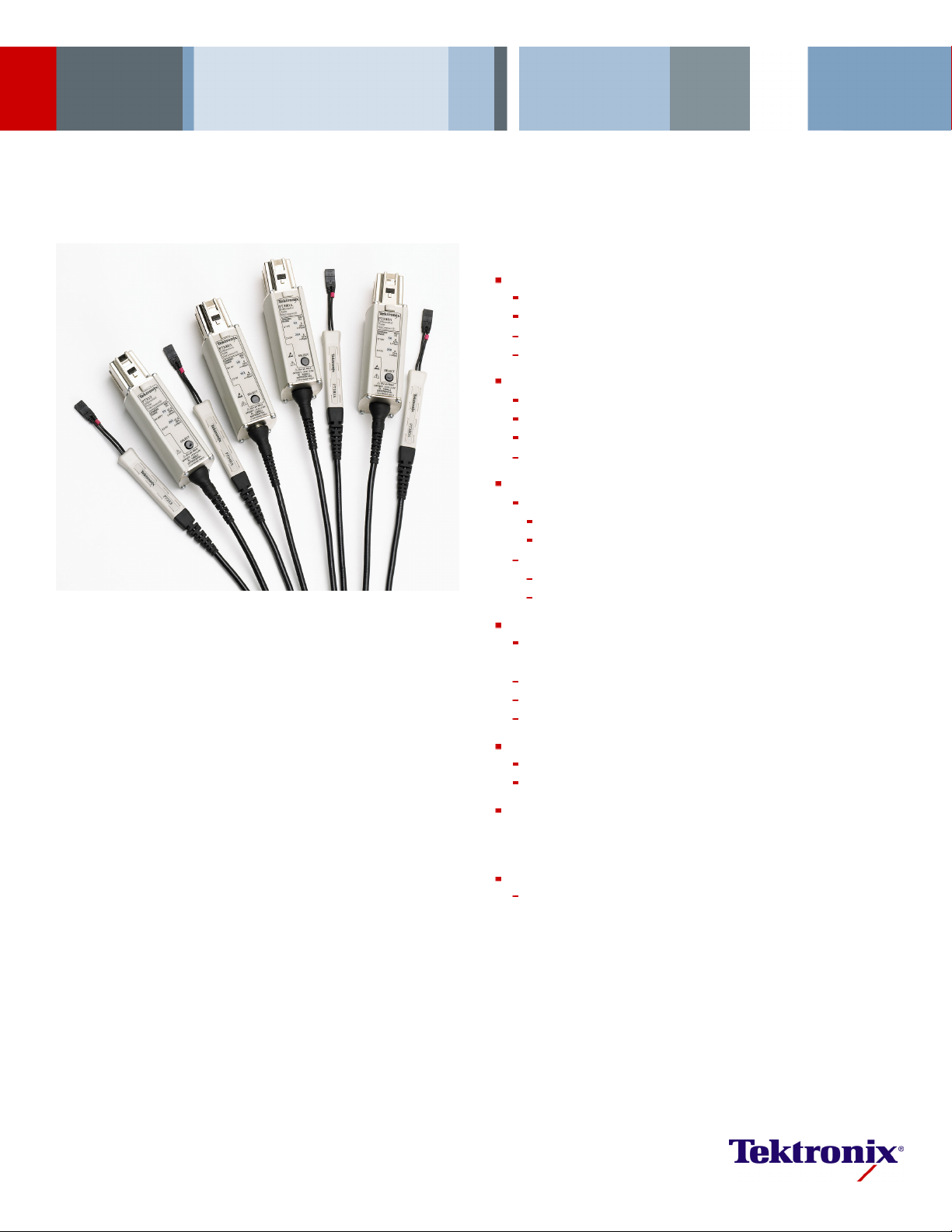
Z-Active™ Differential Probe Family
P7313 • P7380A • P7360A • P7340A Data Sheet
Features & Benefits
Signal Fidelity
>12.5 GHz Bandwidth (P7313, Typical)
>8.0 GHz Bandwidth (P7 380A, Typical)
>6.0 GHz Bandwidth (P7 360A, Typical)
>4.0 GHz Ban
Extended Linear Dynamic Range
1.25 V
4V
2V
5V
Low Probe Loading
DC Input Resistance
AC Loading
Versatility
Make Differential or Single-ended (Ground-referenced)
Measurements*
Solder-down Capability
Handheld Probing with Variable Spacing and Compliance
Fixtured
Interchangeable Tip-Clip™ Assemblies
Connect to a Variety of Devices
Economical
TekConnect®Interface
at 5x Attenuation (P7313)
p-p
at 25x Attenuation (P7313)
p-p
at 5x A
p-p
at 25x Attenuation (P7380A, P7360A, P7340A)
p-p
100 kΩ Diff
50 kΩ Single Ended
Z
>200 Ω out to 10 GHz (P7313)
min
Z
>290 Ω, 4 GHz to 8 GHz (P7380A, P7360A, P7340A)
min
Probing
dwidth (P7 340A, Typical)
ttenuation (P73 80A, P7360A, P7340A)
erential
1
Applications
Examples Include, but are not Limited To:
PCI-Express I and II, Serial ATA II, USB 2.0, DDRII, DDRIII, Fireware
1394b, Rambus, XAUI
*1For details, please see application note 60W-18344-0, “Making Single-ended Measurements with
Differential Probes.”
Page 2

Data Sheet
Z-Active™ Probing Architecture Leads the
Way for High-speed Probing Applications
Tektronix has created a revolutionary Z-Active probe architecture that sets
the industry benchmark for signal fidelity. Tektronix a ctive probe architecture
preserves high bandwidth while providing improved connectivity with low
loading. The Z-Active architecture is a hybrid approach composed of a
distributed attenuator topology feeding an active probe amplifier.
The Z-Active probes use a tiny passive probe tip element that is separa te
from the amplifier, extending the usable reach of the probe. In traditional
active probes, adding this much length can introduce signal fidelity
problems. However this architecture maintains high DC input resistance
and presents
accomplishes this while providing significant length between the probe body
and the probe attachment point to the DUT. This architecture provides the
best of both worlds: high DC impedance like existing active probes and the
stable high-f reque ncy loading of Z
Signal Fidelity
You ca n b e c o n fident in the signal fidelity of your measurements because
the Z-Active architecture provides:
High Bandwidth
Excellent Step Response
Low Loading
High CMRR
Extended Linear Dynamic Range
a higher AC impedance than previous probe architectures. It
probes.
0
Extended Linear Dynamic Range
Many of today’s logic signals and serial bus signals require the capability
to measure up to several volts peak to peak. These voltage levels may
easily be viewed with the Z-Active architecture probes (P7380A, P7360A,
and P7340A) wit
h the extended linear dynamic range. With a 2.0 V
p-p
linear dynamic input range at the 5x attenuation setting, you can accurately
measure DDR II and III, Firewire 1394b, and PCI-Express I and II signals
at reduced noise levels. In addition the 25x attenuation setting’s linear
dynamic input voltage range can be used up to 5.0 V
for accessing even
p-p
larger signal swings found during transition times.
Connectivity
The Z-Active probe design allows the probe to easily switch between
soldered, handheld, or fixtured applications.
This family of probes uses Tip-Clip™ assemblies, an interchangeable
probe tip system that enables customers to configure their probe with the
optimal tip f
or their application. These detachable assemblies make it
possible to replace a tip for a fraction of the cost formerly associated with
such hardware changes. The several lengths and variable spacing of the
assemblies provide flexibility for adapting to vias and other test points of
differing sizes. With Tektronix Tip-Clip assemblies, Monday’s solder-in
probe can become Tuesday’s handheld tool, simply by switching tips.
Value
The combin ation of the Z-Active architecture and the Tip-Clip assemblies
provide superior signal fidelity at a cost-effective price. The inexpensive
Tip-Clip as
semblies enable full-performance solde r connections at a very
low price per connection. Over the life of a probe this can add up to
significant savings in the cost of operation.
2 www.tektronix.com
Page 3

Characteristics
Z-Active™ Differential Probe Family — P7313 • P7380A • P7360A • P7340A
Characteristic
Bandwidth (Typical) >4 GHz >6 GHz >8 GHz >12.5 GHz
Rise Time (10%-90%)
(Guaranteed)
Rise Time (20%-80%) (Typical)
Attenuation 5x or 25x, user selectable
Differential Input Range ±1.0 V (5x)
Linearity Error for Differential
Input Dynamic Range (Typical)
Operating Voltage Window
Offset Voltage Range
DC Input Resistance 100 kΩ
AC Loading (Differential Z
Noise
CMRR
Nondestructive Input Range ±15 V
Interface TekConnect
Cable Length
)>290Ω >200 Ω
min
P7340A P7360A P7380A P7313
>50 dB
>35 d
>20 d
®
<55 ps
at 1 MHz
Bat1GHz
Bat8GHz
±0.625 V (5x)
±0.25% for -0.5 V to +0.5 V (5x)
±0.75% for -0.625 V to +0.625 V (5x)
±0.5% for -1.6 V to +1.6 V (25x)
±1.0% for -2.0 V to +2.0 V (25x)
>50 dB
>35 d
>20 d
>15 d
<100 ps <70 ps
<70 ps <50 ps <35 ps <25 ps
±2.5 V (25x)
±0.5% for -0.5 V to +0.5 V (5x)
±1.0% for -0.75 V to +0.75 V (5x)
±2.0% for -1.0 V to +1.0 V (5x)
±0.5% for -1.5 V to +1.5 V (25x)
±1.0% for -2.5 V to +2.5 V (25x)
±2.0% for -3.0 V to +3.0 V (25x)
+5.0Vto-3.0V +4.0Vto-3.0V
+4.0 V to -3.0 V
<31 nV/√Hz (5x)
<75 nV/√Hz (25x)
at 1 MHz
>50 dB
Bat1GHz
>35 d
Bat4GHz
>20 d
1.5 m 1.5 m 1.2 m 1.2 m
>50 dB
>35 d
>20 d
at 1 MHz
Bat1GHz
Bat6GHz
<40 ps
±2.0 V (25x)
at 1 MHz
Bat1GHz
Bat6GHz
Bat12.5GHz
Ordering Information
P7313
>12.5 GHz Z-Active Differential Probe for TekConnect®Interface.
Includes: See Standard Accessories table.
P7380A
>8.0 GHz Z-Active Differential Probe for TekConnect®Interface.
Includes: See Standard Accessories table.
P7360A
>6.0 GHz Z-Active Differential Probe for TekConnect®Interface.
Includes: See Standard Accessories table.
P7340A
>4.0 GHz Z-Active Differential Probe for TekConnect®Interface.
Includes: See Standard Accessories table.
www.tektronix.com 3
Page 4

Data Sheet
Standard Accessories
Description P7340A P7360A P7380A P7313 Reorder Part Number
Pouch, Nylon Carrying Case with Inserts
Accessory Performance Summary and Reorder
Sheet
User Manual - Printed.
Includes Reply Card and CD
BNC (M)-to-Minigrabber Adapter
Anti-static Wrist Strap
Magnifying Glasses
Calibration Data Report
Handheld Probe Adapter 1 each 1 each 1 each 1 each 015-0717-xx
Accessory Box and Contents
Attachment Kit 1 each 1 each 1 each 1 each
Velcro Fastening Strap
Velcro Fastening Dots 10 each 10 each 10 each 10 each
Adhesive Tip-Clip Tape*
2
(Strip of 10)
Color Band Kit (2 ea. of 5 colors)
Short Flex, Small Resistor Tip-Clip Assembly
Medium Flex, Small Resistor Tip-Clip Assembly
Long Flex, Small Resistor Tip-Clip Assembly
Variable Spacing Tip-Clip Kit
Square Pin Adapter Tip-Clip
Tip-Clip Ejector*
2
Wire Replacement Kit
Short Flex, Large Resistor 1/8 W Tip-Clip
Assembly
Long Flex, Large Resistor 1/8 W Tip-Clip
Assembly
Medium Flex, Large Resistor 1/8 W Tip-Clip
Assembly
*2Tip-Clip Ejectors and Tip-Clip Tape are shipped standard with the 020-xxxx-xx Tip-Clip Assembly Kits.
1 each 1 each 1 each 1 each
1 each 1 each 1 each 1 each
1 each 1 each 1 each 1 each
016-1952-xx Qty 1
001-1389-xx Qty 1
020-2640-xx Qty 1 – Opt. L0
020-2648-xx Qty 1 – Opt. L5
040-2649-xx Qty 1 – Opt. L7
1 each 1 each 1 each 1 each
1 each 1 each 1 each 1 each
1 each 1 each 1 each 1 each
1 each 1 each 1 each 1 each
013-0342-xx Qty 1
006-3415-xx Qty 1
378-0486-xx Qty 1
Opt. D1
1 each P7313: 020-2636-xx
1 each P7380A: 020-2557-xx
1 each P7360A: 020-2690-xx
1 each P7340A: 020-2690-xx
016-1953-xx Qty 1
10 each 10 each 10 each 10 each
–
–
3 each 3 each 3 each 3 each
1 each 1 each 1 each 1 each
2 each 2 each 3 each 3 each
2 each 2 each 3 each 3 each
2 each 2 each 3 each 3 each
3 each 3 each 3 each 3 each
1 each 1 each 1 each 1 each
3 each 3 each 3 each 3 each
–––
3each
020-2596-xx (Kit of 3)
020-2701-xx (Kit of 3)
–
016-1948-xx Qty 1
020-2600-xx Qty 10
020-2602-xx Qty 10
020-2604-xx Qty 10
–
020-2639-xx Qty 10HBW Straight Flex Tip-Clip Assembly
020-2657-xx Qty 5
–––
3each
020-2638-xx Qty 10HBW Right-Angle Flex Tip-Clip Assembly
020-2656-xx Qty 5
–––
––
––
3each
3each
2 each 2 each 3 each
1each
–
–
–
020-2644-xx Qty 1
020-2601-xx Qty 10
020-2605-xx Qty 10
020-2603-xx Qty 10
Recommended Accessories
Description P7360 P7380 P7313 Part Number
Probe Positioner Yes Yes Yes PPM100
Probe Positioner Yes Yes Yes PPM203B
PPM203B, PPM100 Adapter Fixture Yes Yes Yes 013-0339-xx
Calibration Fixture
Yes Yes Yes
P7340A: 067-0419-xx
P7360A: 067-0419-xx
P7380A: 067-0419-xx
P7313: 067-1616-xx
DSA8200 Series TekConnect®Probe Interface
Yes Yes Yes 80A03
Deskew Fixture Yes Yes Yes 067-1586-xx
Real-time Spectrum Analyzer TekConnect Probe
Yes Yes Yes RT PA 2 A
Adapter
4 www.tektronix.com
Page 5

Z-Active™ Differential Probe Family — P7313 • P7380A • P7360A • P7340A
Service Options
Opt. CA1 – Asing
interval, whi
Opt. C3 – Calibration Service 3 Years.
Opt. C5 – Calibration Service 5 Years.
Opt. D3 – Calib
Opt. D5 – Calibration Data Report 5 Years (with Opt. C5).
Opt. G3 – Complete Care 3 Years (includes loaner, scheduled calibration and more).
P7360A, P7380A only
Opt. G5 – Comp
P7360A, P738
Opt. R3 – Repair Service 3 Years.
Opt. R5 – Repair Service 5 Years.
le calibration event or coverage for the designated calibration
chever comes first.
ration Data Report 3 Years (with Opt. C3).
lete Care 5 Years (includes loaner, scheduled calibration and more).
0A only
Language Options
Opt. L0 – English Manual.
Opt. L5 – Jap
Opt. L7 – Simplified Chinese Manual.
Additiona
anese Manual.
l Service Products Available During Warranty
(DW) or Post Warranty (PW)
P7313-CA1 – A single calibration even or coverage for the designated calibration
interval, whichever comes first
PW –
P7313-R1
P7313-R2PW – Repair service coverage 2 year post warranty
P7313-R3DW – Repair service coverage 3 years (includes product warranty period);
3-year period starts at time of customer instrument purchase.
P7313-R
5-year p
P7340A-CA1 – A single calibration even or coverage for the designated calibration
interval, whichever comes first
P7340A-R1PW – Repair service coverage 1 year post warranty
P7340AP7340A-R3DW – Repair service coverage 3 years (includes product warranty period);
3-year period starts at time of customer instrument purchase.
P7340A-R5DW – Repair service coverage 5 years (includes product warranty period);
5-year period starts at time of customer instrument purchase.
P7360A
interv
P7360A-R1PW – Repair service coverage 1 year post warranty
P7360A-R2PW – Repair service coverage 2 year post warranty
P7360
3-yea
P7360A-R5DW – Repair service coverage 5 years (includes product warranty period);
5-year period starts at time of customer instrument purchase.
P7380A-CA1 – A single calibration even or coverage for the designated calibration
interval, whichever comes first
0A-R1PW –
P738
P7380A-R2PW – Repair service coverage 2 year post warranty
P7380A-R3DW – Repair service coverage 3 years (includes product warranty period);
3-year period starts at time of customer instrument purchase.
0A-R5DW –
P738
ar period starts at time of customer instrument purchase.
5-ye
Repair service coverage 1 year post warranty
5DW –
Repair service coverage 5 years (includes product warranty period);
eriod starts at time of customer instrument purchase.
R2PW –
Repair service coverage 2 year post warranty
-CA1 –
A single calibration even or coverage for the designated calibration
al, whicheve r comes first
A-R3DW –
Repair service coverage 3 years (includes product warranty period);
r period starts at time of customer instrument purchase.
Repair service coverage 1 year post warranty
Repair service coverage 5 years (includes product warranty period);
Product(s) are manufactured in ISO registered facilities.
Product(s) complies with IEEE Standard 488.1-1987, RS-232-C, and with Tektronix
Standard Codes and Formats.
www.tektronix.com 5
Page 6

Data Sheet
Contact Tektronix:
ASEAN / Australa
Balkans, Israel, South Africa and other ISE Countries +41 52 675 3777
Central East Eu
Mexico, Central/South America & Caribbean (52) 56 04 50 90
* European toll-free number. Ifnot accessible, call: +41 52 675 3777
rope, Ukraine, and the Baltics +41 52 675 3777
Central Europe & Greece +41 52 675 3777
Asia, and North Africa +41 52 675 3777
Middle E ast,
The Netherlands 0080 0 2255 4835*
People’s Rep
Republic of
United Kingdom & Ireland 00800 2255 4835*
sia (65) 6356 3900
Austria 00800 2255 4835*
Belgium 00800 22
Brazil +55(11)37597600
Canada 1 800 833 9200
Denmark +4580881401
Finland +41526
France 008 00 2255 4835*
Germany 00800 2255 4835*
Hong Kong 400 8
India 000 800 650 1835
Italy 00800 2255 4835*
Japan 81 (3) 67
Luxembourg +41526753777
ublic of China 400 820 5835
Poland +41 52 675 3777
Korea 001 800 8255 2835
Russia & CIS +7 (495) 7484900
South Africa +41526753777
Spain 00800
Sweden 008 00 2255 4835*
Switzerland 00800 2255 4835*
Tai wa n 886 (
55 4835*
75 3777
20 5835
14 3010
Norway 800 16098
Portugal 80 08 12370
2255 4835*
2) 2722 9622
USA 1 800 833 9200
Updated 25 May 2010
www.tektronix.com
For Further Information. Tektronix maintains a comprehensive, constantly expanding
collection of application notes, technical briefs and other resources to help engineers working
on the cutting edge of technology. Please visit www.tektronix.com
t © Tektronix, Inc. All rights reserved. Tektronix products are covered by U.S. and foreign patents,
Copyrigh
d pending. Information in this publication supersedes that in all previously published material.
issued an
tion and price change privileges reserved. TEKTRONIX and TEK are registered trademarks of
Specifica
x, Inc. All other trade names referenced are the service marks, trademarks, or registered trademarks
Tek tro ni
espective companies.
of their r
20 Sep 2010 51W-17891-9
 Loading...