

Page 1

xx
P6717A
General-Purpose Logic Probe
Instruct
ions
Setting u p the Probe
Select Vertical|Digital Setup to set and view the following
parameters of each digital channel:
Threshold voltage and vertical position
Signal height and position (set once for all 16 channels)
Channel label
The default settings are 1.4 V thresholds with digital channel
number labels.
Use the controls in the Bus Setup screen to set and view bus
characteristics such as:
Clock type
Bus type (Serial or Parallel)
Bus width
Display format (Hex, Binary, or ASCII symbols)
Parallel bus setup information is resident on the MSO Family of
oscilloscopes. However, for other buses such as CAN and I2C,
you must have the appropriate option. See your oscilloscope
manual or product data sheet for nomenclature and ordering
details.
Functional Check
Logic activity immediately displays on all connected, active
channels. If you do not see an active signal:
1. Press Trigger.
2. Select Edge for trigger type.
3. Select the channel that you are setting up as the source.
If you do not see an active signal, try another probe channel (or
analog probe) to verify circuit activity at the test point.
Do not Operate Without Covers. Do not touch exposed
connections and components when power is present.
Avoid Exposed Circuitry. Do not touch exposed connections
and components when power is present.
Do Not Operate With Suspected Failures. If you suspect there is
damage to this product, have it inspected by qualified service
personnel.
Do Not Operate in Wet/Damp Conditions. Do Not Operate in an
Explosive Atmosphere.
Keep Product Surfaces Clean and Dry.
Safety Terms and Symbols in This Manual.
These terms may appear i n this manual:
WARNING. Warning statements identify conditions or
practices that could result in injury or loss of life.
CAUTION. Caution statements identify conditions or
practices that could result i n damage to this product or
other property.
Symbols on the Product. This symbol may appear on the
product:
Typical Application
1. Use the P6717A probe to view digital signals on a system
bus.
2. Use iCapture or analog probes, such as the P7508 probes
to view analog waveform information.
1
*P0712
61503*
071-2615-03
Product Description
The P6717A general-purpose logic probe connects the
Tektronix MSO70000 Series of mixed-signal oscilloscopes to
digital buses and signals on your target system. The probe
includes 16 data channels and one clock/data channel. Each
probe channel includes a signal pin and a ground pin. You
can connect the probe leads separately to the target system, or
group the leads together using the probe tip holders.
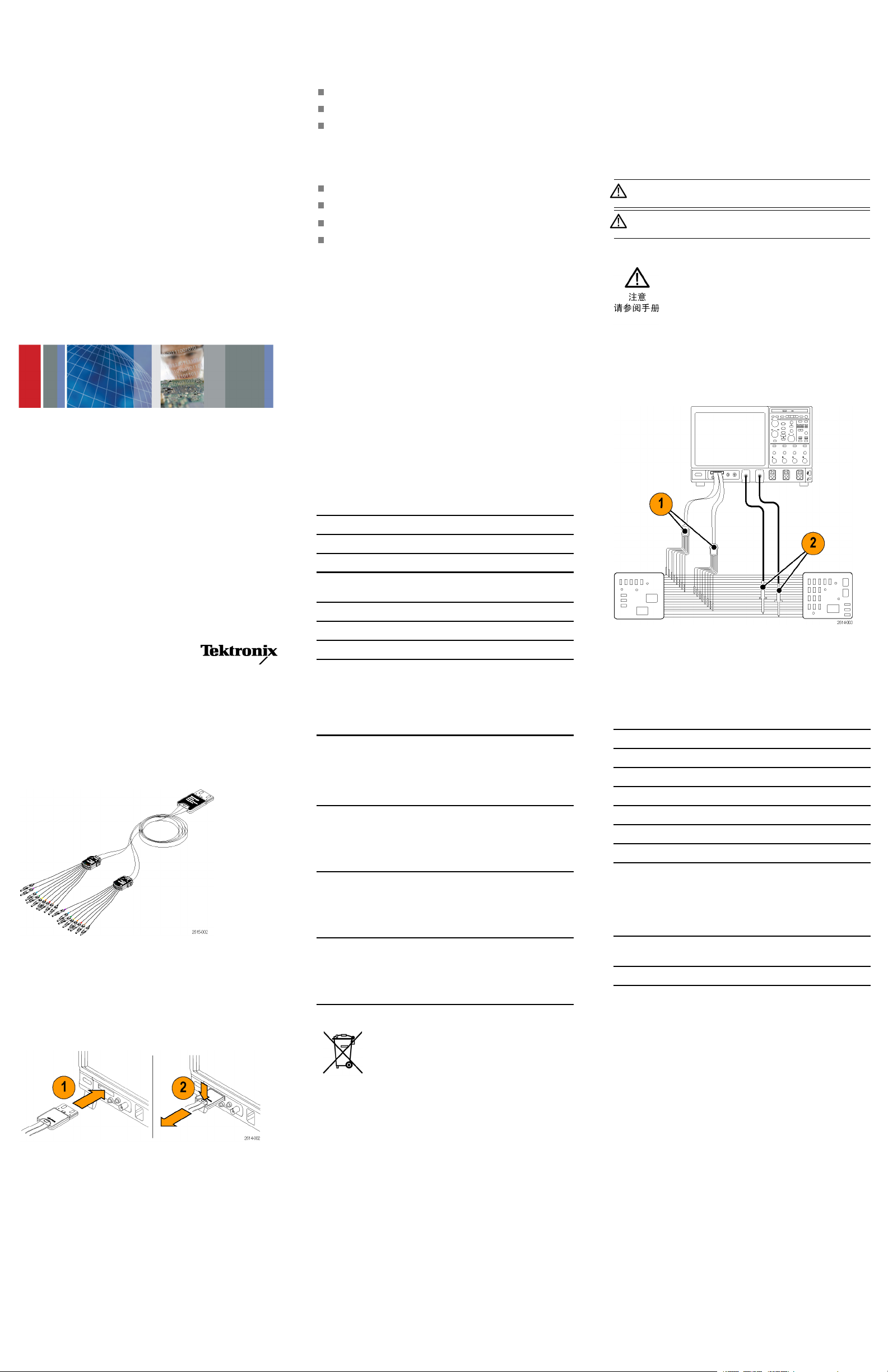
Connecting the Probe to the Oscilloscope
Connect the probe as shown in the illustration below.
1. Insert the probe label-side up into the connector on the
oscilloscope.
2. To remove the probe, push the probe in, press the button,
ull out the probe.
and p
Connecting the Probe to Your Circuit
Attach the probe to the circuit using the connectors and adapters
shown on the back of these instructions. Select the best method
for your needs, and then proceed to Setting up the Probe.
Specifications
Table 1: Electrical and mechanical specifications
Characteristic Description
Input channels 16 data, 1 clock
Bandwidth
Slew rate limit 6 V/ns for signals <2 Vpk-pk
Maximum nondestructive
input signal to probe
Input resistance
Input capacitance 3.0 pF
Probe length
1GHz
±15 V
20 kΩ ±1.0%
1.0 m (3.28 ft)
Table 2: Environmental specifications
Characterist
Temperature
Humidity
Altitude
ic
Maximum operating
Minimum oper
Nonoperating
Operating
Nonoperating
Operating
Nonoperati
ating
ng
Equipment Recycling. This product complies
with the European Union’s requirements according
to Directiv
and electronic equipment (WEEE). For more
information about recycling options, check the
Support/Service section of the Tektronix Web site
(www.tektronix.com).
Description
+50 °C (+122 °F)
0°C(+32°F)
–55°Cto+75°
(–67 °F to +167 °F)
5% to 95% relative humidity at up
to +30 °C (+86 °F)
5% to 75% RH above +30 °C
(+86 °F) up to +50 °C (+122 °F),
noncondensing
5% to 95% relative humidity at up
to +30 °C (+86 °F)
5% to 75% RH above +30 °C
(+86 °F) up to +60 °C (+140 °F),
noncondens
4.6 km (15,092 ft) maximum
4.6 km (15,092 ft) maximum
e 2002/96/EC on waste electrical
C
ing
Safety Summary
Connect and Disconnect Properly. Connect the probe output
to the measurement instrument before c onnecting the probe
to the circuit under test. Disconnect the probe input and the
probe ground from the circuit under test before disconnecting
the probe from the measurement instrument.
Observe All Terminal Ratings. To avoid fire or shock hazard,
observe all ratings and markings on the product. Consult the
product m anual for further ratings information before making
connections to the product.
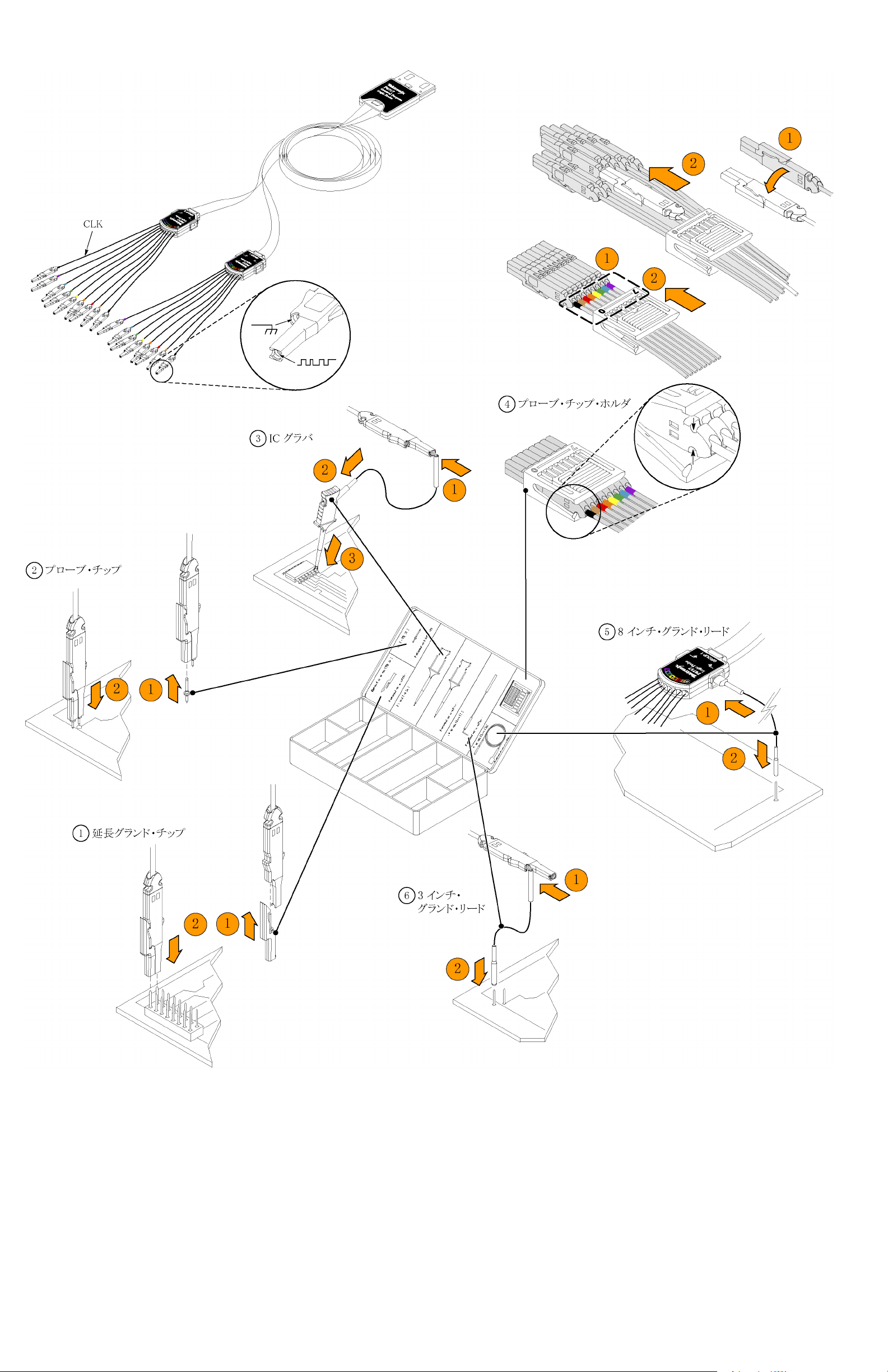
Accessories
The following standard accessories ship with the probe and are
shown in the illustration on the following page.
Item Description Quantity Part number
1 Extension ground tip
2 Probe tip
3
IC grabber 1 set of 20
4 Probe tip holder 2 ea 352-1115-XX
5
8” Ground lead 1 set of 2
6
3” Ground lead 1 set of 8
Instructions
(multilanguage)
1 set of
1 set of 10
1 ea 071-2615-XX
20
020-2711-XX
131-5638-11
020-2733-XX
020-2713-XX
020-2712-XX
These optional accessories can be ordered for your probe:
Description Part number
P6960 Probe D-MAX Footprint to
Square Pin Header Adapter
Digital Probe Deskew Fixture 067-2083-XX
NEX-P6960PIN
Contacting Tektronix
Web site: www.tektronix.com
Phone: 1-800-833-9200
Address: Tektronix, Inc.
Email:
Department or name (if known)
14200 SW Karl Braun
Drive P.O. Box 500
Beaverton, OR 97077
USA
techsupport@tektronix.com
Warranty Information
For warranty information, go to www.tektronix.com/warranty.
x
Page 2

Connecting the Probe to the Circuit
Copyright © Tektronix, Inc. All rights reserved. www.tektronix.com
Page 3

xx
P6717A 型
汎用ロジック・プローブ
取扱説明書
プローブのセットアップ
Vertical > Digital Setup を選択して、各デジタル・チャンネル
の下記パラメータを設定または表示します。
スレッショルド電圧と垂直軸位置
信号高さおよび位置(全 16 チャンネルを一括設定)
チャンネル・ラベル
デフォルト設定は、スレッショルド電圧 1.4 V、デジタル・チャ
ンネル番号ラベルとなっています。
Bus Setup 画面のコントロールを使用して、以下のバス特性
を設定または表示します。
クロックの種類
バスの種類(シリアルまたはパラレル)
バス幅
表示形式(16 進、2 進、または ASCII シンボル)
パラレル・バスのセットアップ情報は、MSO ファミリのオシロス
コープに保存されています。しかし CAN や I2C など、その
他のバスについては適切なオプションが必要です。名称と発
注情報については、ご使用のオシロスコープのマニュアルま
たは製品データ・シートを参照してください。
機能チェック
接続されたすべてのアクティブなチャンネルについて、ロジッ
ク動作が直ちに表
示されます。アクティブな信号が表示され
ない場合は、次の操作を行ってください。
1. Trigger を押しま す。
2. トリガのタイプとして Edge を選択します。
3. ソースとしてセットアップするチャンネルを選択します。
アクティブな信号が表示されない場合は、他のプローブ・チャ
ンネル(またはアナログ・プローブ)を使用して、テスト・ポイン
トの回路動作を確認してください。
回路の露出を避けてください: 電源がオンのときに、露出し
た接続部分やコンポーネントに触れないでください。
故障の疑いがあるときは使用しないでください: 本製品に
故障の疑いがある場合、資格のあるサー ビス担当者に検査
してもらってください。
湿気の多いところでは使用しないでください: 爆発性ガスが
充満している場所では使用しないでください。
製品の表面を清潔で乾燥した状態に保ってください:
安全に関する用語と記号
このマニュアルでは次の用語を使用します。
警告: 人体や生命に危害をおよぼすおそれのある状態
や行為を示します。
注意: 本製品やその他の接続機器に損害を与える状態
や行為を示します。
本製品の記号: 本製品は以下の記号に注意してご使用くだ
さい。
主な用途
1. P6717A 型プローブは、システム・バスのデジタル信号の
観測に使用します。
2. iCapture または P7508 型プローブなどのアナログ・プ
ローブを使用してアナログ波形情報を観測します。
2
15-03
071-26
製品の説明
P6717A 型汎用ロジック・プローブは、当社 MSO70000 シリー
ズ・ミックスドシグナル・オシロスコープをターゲット・システム
のデジタル・バスおよび信号に接続するために使用します。
本プローブには、16 のデータ・チャンネルと 1 つのクロック/
データ・チャンネルがあります。各プローブ・チャンネルは、一
対の信号ピンとグランド・ピンで構成されます。プローブ・リー
ドは、ターゲット・システムに個別に接続すること、および、プ
ローブのチップ・ホルダを使用してグループ化することがで
きます。
プローブ
以下の図に示すようにプローブを接続します。
1. ラベル面を上にして、プローブをオシロスコープのコネ
2. プローブを取り外すには、まずプローブを押し込み、ボ
プローブと測定回路の接続
プローブを回路に接続するには、本書の最後に記載されて
いるコネクタとアダプタを使用します。ニーズに最も合った方
法を使用し、後は「プローブのセットアップ」の指示に従って
ください。
とオシロスコープの接続
クタに挿入します。
タンを押してからプローブを引き抜きます。
仕様
表 1: 電気仕様と機械仕様
特性 説明
入力チャンネル
帯域幅
转换速率限制 信号 <2 Vpk-pk 时为 6V/ns
プローブに対する最大非
破壊入力信号
入力抵抗
入力キャパシタンス
プローブ長
16 データ、1 クロック
1GHz
±15 V
20 kΩ ±1.0%
3.0 pF
1.0 m (3.28 フィート)
表 2: 環境仕様
特性 説明
温度
動作時最高温度
動作時最低温度
非動作時
湿度
動作時
非動作時
高度
動作時
非動作時
機器のリサイクル: 本製品は WEEE Directive
2002/96/EC (廃棄電気・電子機器に関する指
令)に基づく EU の諸要件に準拠しています。リ
サイクル方法の詳細については、当社 Web サ
イト(www.tektronix.com)の「Support/Service」を
参照してください。
+50 ℃ (+122 ゚F)
0℃(+32゚F)
–55 ℃ ~ +75 ℃
(–67 ゚F ~ +167 ゚F)
+30 ℃(+86 ゚F) 以 下で相対湿
度 5% ~ 95%
+30 ℃(+86 ゚F)~ +50 ℃(+122
゚F)で相対湿度 5% ~ 75% (結
露のない状態)
+30 ℃(+86 ゚F) 以 下で相対湿
度 5% ~ 95%
+30 ℃(+86 ゚F)~ +60 ℃(+140 ゚
F)で相対湿度 5% ~ 75% (結露
のない状態)
4.6 km(15,092 フィート)まで
4.6 km(15,092 フィート)まで
安全にご使用いただくために
接続と切断の手順を守ってください: 測定対象の回路にプ
ローブを接続する前に、プローブ出力を計測機器に接続し
てください。計測機器からプローブを外す前に、測定対象の
回路からプローブの入力とグランドを外してください。
すべての端子の定格に従ってください: 火災や感電の危険
を避けるために、本製品のすべての定格とマーキングに従っ
てください。本製品に電源を接続する前に、定格の詳細につ
いて、製品マニュアルを参照してください。
カバーを
外した状態では使用しないでください: 電源がオン
のときに、露出した接続部分やコンポーネントに触れないで
ください
。
アクセサリ
本プローブには下記の表に示すスタンダード・アクセサリが
付属しています。次ページの図を参照してください。
項
目 説明 数量 部品番号
1
延長グランド・チップ
2
プローブ・チップ 10 個 入 り
3
IC グラ バ
4
プローブ・チップ・ホルダ2個
5
8インチ・グランド・リード
6
3インチ・グランド・リード
取扱説明書(多言語版)
20 個 入 り
セット
セット
20 個 入 り
セット
2本入り
セット
8本入り
セット
1部
020-2711-XX
131-5638-11
020-2733-XX
352-1115-XX
020-2713-XX
020-2712-XX
071-2615-XX
下記のオプショナル・アクセサリをご購入いただけます。
説明 部品番号
P6960 型プローブ D-MAX フットプリ
ント用スクエア・ピン・ヘッダ・アダプタ
デジタル・プローブ・デスキュー・フィ
クスチャ
NEX-P6960PIN
067-2083-XX
Tektronix 連 絡先
Web サイト:
電話番号:
住所:
電子メール・アド
レス:
について
保証
http://www.tektronix.com
1-800-833-9200
Tektronix, Inc.
部署名または個人名(わかる場合)
14200 SW Karl Braun
Drive P.O. Box 500
Beaverton, OR 97077
USA
techsupport@tektronix.com
保証の詳細については、http://www.tektronix.com/warranty
クセスしてください。
にア
x
Page 4
プローブと測定回路の接続
Copyright (C) Tektronix, Inc. All rights reserved. www.tektronix.com
Page 5
xx
P6717A
通用逻辑探头
设置探头
选择 Vertical|Digital Setup(垂直|数字设置)设置和
查看每个数字通道的下列参数:
阈值电压和垂直位置
信号高度和位置(一次设置用于所有 16 个通道)
通道标签
默认设置为 1.4 V 阈值,带数字通道编号标签。
使用 Bus Setup(总线设置)屏幕上的控制来设置和查看
总线特征,例如:
时钟类型
总线类型(串行或并行)
总线宽度
显示格式(十六进制、二进制或 ASCII 符号)
并行总线设置信息驻留在 MSO 系列示波器内。但对于其
他总线(如 CAN 和 I2C),则必须有合适的选件。参阅
示波器手册或产品数据表了解术语和订购细节。
切勿开盖操作: 电源接通后请勿接触外露的接头和元件。
远离裸露电路: 电源接通后请勿接触外露的接头和元件。
有可疑故障时不要操作: 如果您怀疑此产品已损坏,可请
合格的维修人员进行检查。
请勿在潮湿环境下操作: 请勿在易燃易爆的环境下操作。
请保持产品表面清洁干燥:
本手册中使用的安全术语和符号。
本手册中可能使用以下术语:
警告: “警告”声明指出可能会危害生命安全的条件
和行为。
注意: “注意”声明指出可能导致本产品和其它财产
损坏的条件和行为。
产品上的符号: 产品上可能出现以下符号:
3
071-26
使用说明
15-03
功能检查
逻辑活动立即显示在所有连接的活动通道上。如果看不到
活动信号:
1. 按下 Trigger(触发)。
2. 选择 Edge(边沿)触发类型。
3. 选择正在设置的通道作为信号源。
如果看不到活动信号,请尝试其他探头通道(或模拟探
头)来验证测试点的电路活动。
技术指标
表 1: 电气和机械技术规格
特性 说明
输入通道 16 个数据通道,1 个时钟通道
带宽
スルーレート限界
到探头的最大无损
号
输入电阻
输入电容
探头长度 1.0 米(3.28 英尺)
输入信
1GHz
2 Vpk-pk 以下の信号で 6 V/ns
±15 V
20 kΩ ±1.0%
3.0 pF
典型应用
1. 使用 P6717A 探头查看系统总线上的数字信号。
2. 使用 iCapture 或模拟探头(如 P7508 探头)查看
模拟波形信息。
附件
以下标准附件随探头附带,如下页插图所示。
产品说明
P6717A 通用探头将 Tektronix MSO70000 系列混合信号示
波器连接到目标系统上的数字总线和信号。探头包含 16
个数据通道和一个时钟/数据通道。每个探头带有一个信
号针和一个接地针。可将探头引线分别连接到目标系统,
或者使用探头端部支持臂将引线分组。
将探头连
如下所示连接探头。
1. 将探头标签面朝上插入示波器上的连接器。
2. 要取下探头,请将探头往里推,按下按钮,然后将探
将探头连接到电路
使用这些使用说明背面所示的连接器和适配器,将探头连
接到电路。选择适合需要的最佳方法,然后进入“设置探
头”。
接到示波器
头拔出。
表 2: 环境技术规格
特性 说明
温度
工作状态最大
工作状态最小
非工作状
湿度
工作状态
非工作状 态 在不高于 +30℃(+86℉)时,
海拔高
工作状态
非工作状态
态
度
设备的回收。 本产品符合欧盟根据关于废
弃电 气、 电子 设备 (WEEE) 的 Directive
2002/96/EC 所制定的要求。有关选件回
收的更多信息,请查看 Tektronix 网 站
(www.tektronix.com) 上的 Support/Service
(支持/服务)部分。
+50℃(+122℉)
0℃(+32℉)
至 +75℃
-55℃
(–67℉ 至 +167℉)
在不高于 +30℃(+86℉)时,
相对湿度为 5% 至 95%
在 +30℃(+86℉) 至 +50℃
(+122℉)之间,相对湿度为
5% 至 7
相对湿度为 5% 至 95%
在 +30℃(+86℉) 至 +60℃
(+140℉)之间,相对湿度为
5% 至 75%,无凝结
4.6 千 米 ( 15,092 英尺 )最
大
4.6 千 米 ( 15,092 英尺 )最
大
5%,无凝结
安全概要
正确连接和断开: 在探头连接到测试电路之前,先将探头
输出连接到测量仪器。将探头与测量仪器断开之前,请先
将探头输入端及探头接地与被测电路断开。
遵循所有终端额定值: 为避免火灾或电击危险,请遵守产
品上所有的额定值和标记说明。在连接产品之前,请先查
看产品手册,了解额定值的详细信息。
项
目 说明 数量 部件号
1
延长接地端部 1 套 20 支
2
探头端部 1 套 10 支
3
IC 抓取 器
4
探头端部支持臂 各 2
5
8”接地引线 1套2支
6
3”接地引线 1套8支
使用说明(多语言) 各 1
1套20支
020-2711-XX
638-11
131-5
020-2733-XX
352-1115-XX
020-2713-XX
020-2712-XX
071-2615-XX
可为探头订购下列可选附件:
说明 部件号
P6960 探头 D-MAX 封装至方针插座
适配器
数字探头相差校准夹具
NEX-P6960PIN
067-2083-XX
Tektronix 联系信息
网站:
电话:
地址:
电子邮件:
www.tektronix.com
1-800-833-9200
Tektronix, Inc.
部门或姓名(如已知)
200 SW Karl Braun
14
Drive P.O. Box 500
Beaverton,OR 97077
USA(美国)
techsupport@tektronix.com
保修信息
有关保修信息,请访问 www.tektronix.com/warranty。
x
Page 6

将探头连接到电路
Copyright © Tektronix, Inc. 保留所有权利。 www.tektronix.com
Page 7

xx
P6717A
Логический пробник общего назначения
Руководс
тво по эксплуатации
Настройка пробника
Выберите Vertical|Digital Setup (вертикальная/цифровая
настройка) для установки и просмотра приведенных ниже
параметров каждого цифрового канала:
Пороговое напряжение и положение по вертикали
Высота и положение сигнала (устанавливается один
раз для всех 16 каналов)
Метка канала
По умолчанию пороговые значения составляют 1,4 Ви
имеют метки в соответствии с номером цифрового
канала.
Используйте элементы управления на экране Bus
Setup (настройка шины) для установки и просмотра
характеристик шины, таких как:
Тип синхронизации
Тип шины (последовательный или параллельный)
Ширина шины
Формат дисплея (шестнадцатиричный, двоичный или
символы ASCII)
Информация по установке параллельной шины содержится
в памяти осциллографов серии MSO. Однако для других
шин, таких как шины CAN и I2C, необходимо иметь
соответствующий выбор. Подробнее о номенклатуре
и порядке оформления заказа см. в руководстве или
спецификации своего осциллографа.
Проверка работоспособности
Активность логики сразу же отображается на всех
подсоединенных, активных каналах. Если активного
сигнала не видно:
1. Нажмите кнопку Trigger (установить синхронизацию).
2. Выберите пункт Edge (фронт), чтобы установить тип
синхронизации.
3. Выберите канал, который будет являться источником.
Если активного сигнала не видно, попробуйте использовать
другой канал пробника (или аналоговый пробник), чтобы
проверить активность цепи в контрольной точке.
отсоединяйте его вход и провод заземления от тестируемой
системы.
Проверяйте допустимые номиналы для всех разъемов. Во
избежание воспламенения или поражения электрическим
током проверьте все допустимые номиналы и маркировку
на приборе. Перед подсоединением прибора просмотрите
дополнительные сведения по номинальным ограничениям,
содержащиеся в руководстве по эксплуатации прибора.
Не используйте прибор с открытым корпусом. Не
прикасайте
сь к неизолированным соединениям и
компо нен т ам, находящимся под напряжением.
Избегайте прикосновений к оголенным участкам цепи. Не
прикасайте
сь к неизолированным соединениям и
компо нен т ам, находящимся под напряжением.
Не пользуйтесь неисправным прибором. Если у вас
возникло пр
едположение о возможной неисправности
прибора, попросите квалифицированного специалиста
сервисного
Не пользуйт
центра проверить его.
есь прибором в условиях повышенной
влажности. Не пользуйтесь прибором во взрывоопасных
средах.
Не допуска
йте попадания влаги и загрязнений на поверхность
прибора.
Условные обозначения и символы, относящиеся к
безопасности, используемые в данном руководстве по
эксплуатации.
Ниже приво
дится список условных обозначений,
используемых в данном руководстве по эксплуатации.
ПРЕДУПРЕЖ
ДЕНИЕ. Предупреждения о действиях
и условиях, представляющих угрозу для жизни или
способных
ОСТОРОЖНО
нанести вред здоровью.
. Предостережения о действиях и
условиях, способных привести к повреждению данного
прибора ил
и другого оборудования.
Символы, встречающиеся на изделии. Ниже приводится
символ, в
стречающийся на изделии:
4
15-03
071-26
Описание прибора
Логический пробник P6717A общего назначения соединяет
осциллографы смешанных сигналов Tektronix серии
MSO70000 с шинами передачи данных и сигналов
исследуемой системы. Пробник имеет 16 каналов передачи
данных и один канал синхронизации/передачи данных.
Каждый канал пробника содержит сигнальный штырь и
штырь заземления. Концы пробника можно подсоединять
к исследуемой системе по отдельности, аможно
группировать их при помощи держателей наконечников
пробника.
Подсоединение пробника к осциллографу
Подсоедините пробник, как показано на рисунке внизу.
1. Вставьте пробник этикеткой вверх в разъем
осциллографа.
2. Чтобы удалить пробник, засуньте пробник, нажмите
защелку и вытащите пробник.
Подсоединение пробника к цепи
Присоедините пробник к цепи при помощи разъемов и
адаптеров, изображенных на оборотной стороне данного
руководства по эксплуатации. Выберите наиболее
подходящий метод, после чего перейдите к разделу
«Настройка пробника».
Технические характеристики
Таблица 1: Электрические и механические характеристики
Характеристика Описание
Входные каналы 16 данные,1синхронизация
Полоса пропускания
Предел скорости нарастания
Максимальный
неразрушающий входной
сигнал для пробника
Входное сопротивление
Входная емкость 3,0 пФ
Длина пробника
1GГц
6 В/нс для сигналов <2 Вразмах
(pk-pk)
±15 В
20 кОм ±1,0%
1,0 м
Таблица 2: Условия эксплуатации
Характеристика Описание
Температура
Максимальная рабочая
Минимальная рабочая
При хранении
Влажность
При эксплуатации
При хранении
Высота над уровнем моря
При эксплуатации
При хранении
Утилизация оборудования. Этот прибор
соответствует требованиям Европейского Союза
согласно Директиве 2002/96/EC об утилизации
электрического и электронного оборудования
(WEEE). Болееполныесведенияобусловиях
утилизации см. в разделе технической поддержки
на веб-узле Tektronix (www.tektronix.com).
ие положения о безопасности
Общ
50 °C
0°C
Oт –55 до 75 °C
Относительная влажность от 5 до
95 % при температуре до 30 °C,
Относительная влажность от 5 до
75 % при температуре от 30 до
50 °C, без конденсации
Относительная влажность от 5 до
95 % при температуре до 30 °C,
Относительная влажность от 5 до
75 % при температуре от 30 до
60 °C, без конденсации
4,6 км, максимум
4,6 км, максимум
Соблюдайте правила подсоединения и отсоединения. Перед
соединением пробника к тестируемой системе
под
подсоединяйте его выход к измерительному прибору.
ед отсоединением пробника от измерительного прибора
Пер
Типичный способ применения
1. Использ
уйте пробник P6717A для просмотра
цифровых сигналов на системной шине.
2. Используйте пробники iCapture или аналоговые, такие
как пробник P7508, для просмотра информации в виде
аналоговой осциллограммы.
длежности
Прина
Следующие стандартные принадлежности поставляются
е с пробником и показаны на рисунке, расположенном
вмест
на следующей странице.
Элемент Описание Количество
1 Удлинительный
2 Наконечник
3
4 Держатель
5
6 Провод заземления
наконечник для
ления
зазем
пробника
Захват для ИС
наконечника
пробника
Провод заземления
203,2 мм
76,2 мм
трукции (на
Инс
разных языках)
1 комплект из 20 020-2711-XX
1 комплект из 10 131-5638-11
1 комплект из 20 020-2733-XX
2 шт. 352-1115-XX
1 комплект из 2 020-2713-XX
1 комплект из 8 020-2712-XX
1 шт. 071-2615-XX
Номер по
каталогу
x
Page 8

Для пробника можно заказать следующие дополнительные
принадлежности:
Описание Номер по каталогу
Опорная пло
P6960 для адаптера с квадратными
контактами
Устройство компенсации цифрового
пробника
щадка D-MAX пробника
NEX-P6960PIN
067-2083-XX
Подсоединение пробника к цепи
как связаться с компанией Tektronix
Веб-узел:
Телефон: 1-800-833-9200
Адрес: Tektronix, Inc.
Электронна
почта:
я
www.tektron
Отдел или имя (если известно)
14200 SW Karl Braun
Drive P.O. Box 500
Beaverton, OR 97077
USA
techsuppor
ix.com
t@tektronix.com
Гарантийные обязательства
Информацию о гарантийных обязательствах см. на
веб-сайте www.tektronix.com/warranty.
© Tektronix, Inc., Все права защищены. www.tektronix.com
 Loading...