


Product Description
The P6516 logic probe connects the Tektronix MSO4000
Series mixed--signal oscilloscopes to digital buses and
signals on your target system. The probe contains 16 data
channels split between two lead sets (GROUP 1 and
GROUP 2).
The first lead in each set is identified by blue insulation, and
the remaining seven leads are gray. All leads include a
ground connection at the tip.
Connecting the Probe to Your Circuit
You can attach the probe to the circuit in many ways using
the connectors and adapters shown on the back of these
instructions. Select the best method for your needs, and then
proceed to S etting up the Probe.
Setting up the Probe
Press the D15--D0 button to set and view the following
parameters of each digital channel:
H Threshold voltage and vertical position
H Signal height (set once for all 16 channels)
H Channel label
The default settings are 1.4 V threshold with no labeling.
D15 - D0
Functional Check
Logic activity immediately displays on all connected, active
channels. If you do not see an active signal:
1. Press Trigger
2. Select Edge for trigger type
3. Select the channel that you are setting up as the source
4. Press Autoset
If you do not see an active signal, try another probe channel
(or analog p robe) to verify circuit activity at the test point.
Typical Application
1. Use the P6516 probe to view digital signals on a system
bus.
2. Use P6139A probes to view analog waveform
information.
Connecting the Probe to the Oscilloscope
1. Insert the probe label--side up into the receptacle.
1
2
2. To remove the probe, squeeze the buttons on the side
and pull out the probe.
Use the B1 through B4 buttons to set and view bus
characteristics such as:
H C lock edge type
H Number of bits
H Display format
Parallel bus setup information is resident on MSO4000
Series oscilloscopes. However, for other buses such as CAN
and I2C, you must have the appropriate module and
application k eys. See your oscilloscope manual for more
information.
B1
B2
B3
B4
1
Probe Lead Sets
Blue probe
Brown probe
Red probe
Orange probe
Yellow probe
Green probe
Blue probe
Violet probe
GROUP 1
0
1
2
3
4
5
6
7
2
GROUP 2
8
9
10
11
12
13
14
15
Electrical and Mechanical Specifications
Characteristic Description
Input channels 16
Threshold voltage range -- 2 V to +5 V
Threshold accuracy ±100 mV + 3% of threshold
Minimium signal swing 500 mV p--p
Maximium signal swing 6.0 V p--p centered around the
Maximum nondestructive input
signal to probe
Input resistance 20 KW
Input capacitance 3.0 pF typical
Minimum detectable input pulse 1.5 ns
Probe length 0.9 m (3 ft)
setting
threshold voltage
±15 V
Environmental Specifications
The probe is designed to meet Tektronix standard
062-2847-00 class 5.
Characteristic Description
Temperature
Maximum operating
Minimum operating
Nonoperating --55° C to +75° C
Humidity 10 to 95% relative humidity
Altitude
Operating 4.5 km (15,000 ft) maximum
Nonoperating 15 km (50,000 ft) maximum
Electrostatic Immunity The probe is not static sensitive
Equipment Recycling. This product complies
with the European Union’s requirements
according to Directive 2002/9 6/EC on waste
electrical and electronic equipment (WEEE).
For more information about recycling
options, check the Support/Service section of
the Tektronix Web site (www.tektronix.com).
+50 ° C (+122 ° F)
0 ° C (+32 ° F)
(--67° F to +167 ° F)
Standard Accessories
The following standard accessories ship with the probe and
are shown on the back of these instructions.
Description Quantity Part number
Extension Ground Tip 20 ea 206--0559--XX
Probe Tip 1 set of 10 131--5638--11
IC Grabber 20 ea 206--0569--XX
Lead set 8 ea 196--3501--XX
Ground lead set
Grouper
2 ea 196--3497--XX
2 ea 352-- 1115--XX
Additional Accessories and Test Solutions
The following accessories are also available:
Use Nomenclature Description
Probing P6139A 10X, 500 MHz Passive Voltage Probe
TAP1500 10X, 1.5 GHz Active Voltage Probe
TCP0030 AC/DC 120 MHz Current Probe
Application
module
DPO4AUTO Automotive Serial Triggering and
Analysis Module
DPO4EMBD Embedded Serial Triggering and
Analysis Module
DPO4COMP RS--232 Serial Triggering and
Analysis Module
Warranty Information
For warranty information, go to
www.tektronix.com/warranty
Contacting Tektronix
Tektronix, Inc.
14200 SW Karl Braun Drive
PO Box 500
Beaverton, OR 97077
USA
For product information, sales, service, and technical
support:
H In No rth America, call 1--800--833--9200.
H Worldwide, visit www.tektronix.com to find contacts in
your area.
P6516
Digital Probe
Instructions
P*071214901*
071-2149-01
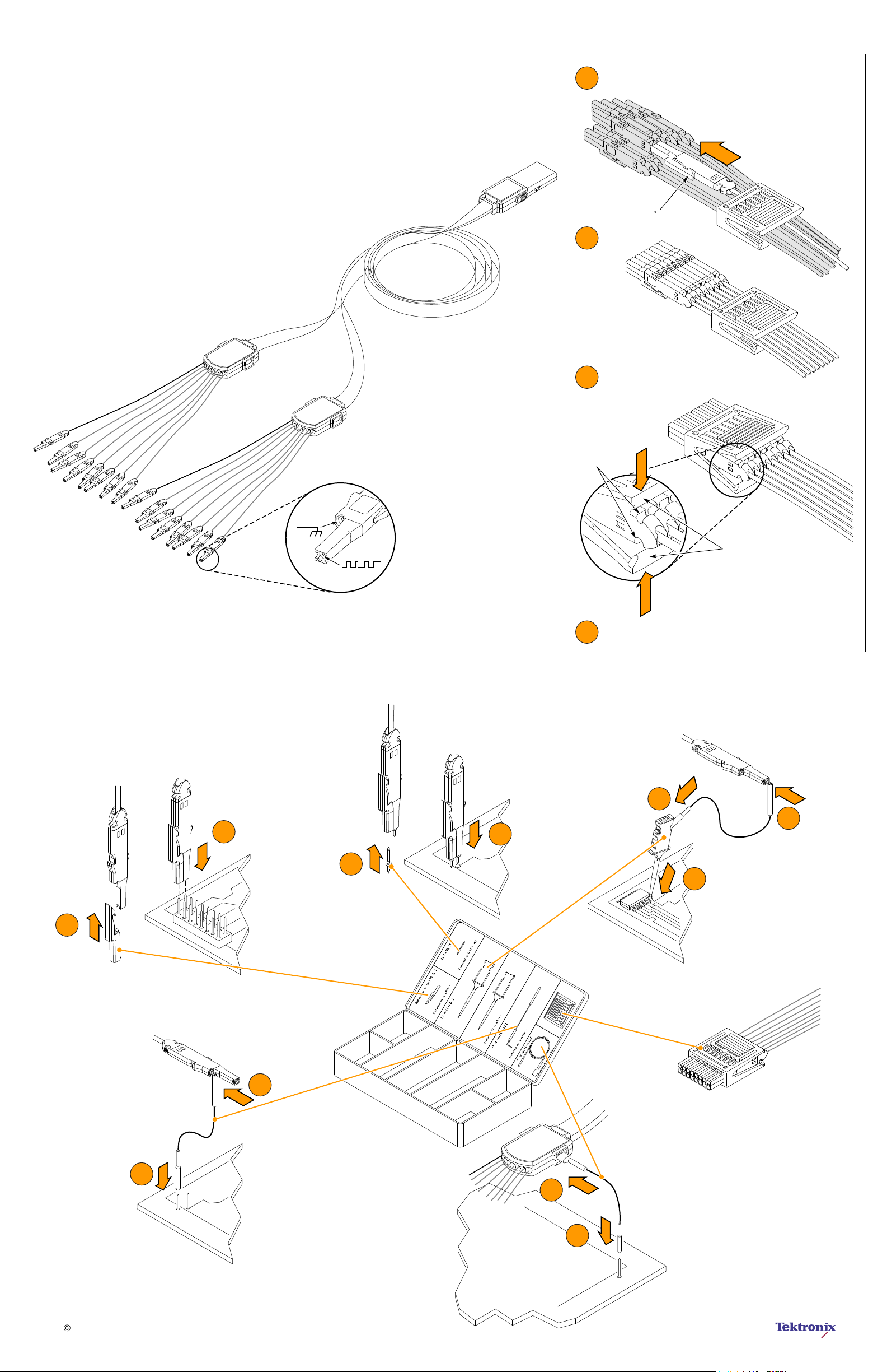
Standard Accessories
Install leads Individually through grouper
1
Rotate 90 to install
2
Align leads
Slide grouper over the leads to engage
3
retention tangs into notches
Notches
4
To disassemble, reverse the procedure
Retention tangs
2
1
2
2
1
3
1
1
Copyright Tektronix, Inc.
2
1
2
 Loading...