

Page 1

Instructions
118-9477-01
118-9478-01
118-9487-01
Mictor Connector and Cable Replacement
P6434 Mass Termination Probe
075-0480-00
Warning
The servicing instructions are for use by
qualified personnel only. To avoid personal
injury, do not perform any servicing unless you
are qualified to do so. Refer to all safety
summaries prior to performing service.
Page 2

Copyright © T ektronix, Inc. All rights reserved.
T ektronix products are covered by U.S. and foreign patents, issued and pending. Information in this publication supercedes
that in all previously published material. Specifications and price change privileges reserved.
Printed in the U.S.A.
T ektronix, Inc., P.O. Box 1000, Wilsonville, OR 97070–1000
TEKTRONIX and TEK are registered trademarks of T ektronix, Inc.
Page 3

Kit Description
This kit includes parts and instructions to service the P6434 Mass Termination
Probe (see Figure 1). The specific parts included with this kit depend on which
service kit you ordered. See page 2 for part lists of the electrical service kits
available for the P6434 probe. Refer to your manual for mechanical service kit
information.
NOTE. These service kits include upgraded components that require specific
installation procedures that differ from those in the P6434 Instructions, part
numbers 070-9793-00 and -01. If you have either of those versions, you must use
these instructions for servicing your P6434 probe.
Probe tip
Figure 1: P6434 Mass Termination Probe
Minimum Tool and Equipment List
Quantity Description
1 ea Tweezers
2 ea Small, flat-bladed screwdriver
1 ea 0.050 inch hexagonal screwdriver
Module ends
Mictor Connector and Cable Replacement, P6434 Probe
1
Page 4
Kit Description
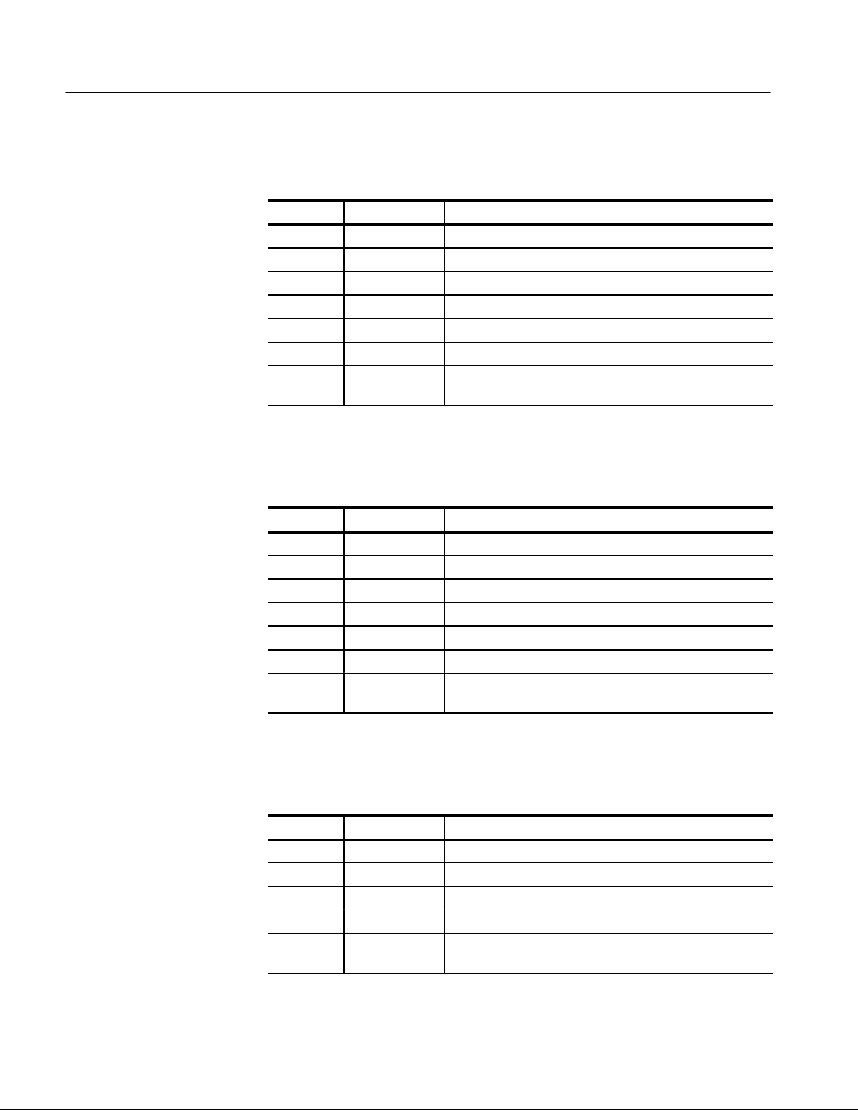
Kit Parts List for 118-9477-01
Quantity Part number Description
2 ea NS ELASTOMER CONNECTOR
1 ea NS SP ACER STRIP, PLASTIC
1 ea NS BOARD HOLDER, MOLDED
2 ea NS PULL GRIP HALVES
2 ea NS PULL GRIP CORD
1 ea NS PIN 1 SIDE CABLE WITH CIRCUIT BOARDS
1 ea NS INSTRUCTION, KIT: MICTOR CONNECTOR AND CABLE
NS–Not Saleable
Kit Parts List for 118-9487-01
REPLACEMENT, P6434 PROBE
Quantity Part number Description
2 ea NS ELASTOMER CONNECTOR
1 ea NS SP ACER STRIP, PLASTIC
1 ea NS BOARD HOLDER, MOLDED
2 ea NS PULL GRIP HALVES
2 ea NS PULL GRIP CORD
1 ea NS PIN 38 SIDE CABLE WITH CIRCUIT BOARDS
1 ea NS INSTRUCTION, KIT: MICTOR CONNECTOR AND CABLE
NS–Not Saleable
Kit Parts List for 118-9478-01
Quantity Part number Description
2 ea NS ELASTOMER CONNECTOR
1 ea NS SP ACER STRIP, PLASTIC
1 ea NS BOARD HOLDER, MOLDED
1 ea NS MICTOR CONNECTOR BD WITH MICTOR CONNECT OR
1 ea NS INSTRUCTION, KIT: MICTOR CONNECTOR AND CABLE
REPLACEMENT, P6434 PROBE
REPLACEMENT, P6434 PROBE
NS–Not Saleable
2
Mictor Connector and Cable Replacement, P6434 Probe
Page 5

Installation Instructions
The following procedures instruct you to install any of the three service kits
listed on page 2. If you are only installing the connector parts kit, follow the
Probe Tip procedures on pages 3 and 6. If you are installing either of the cable
parts kits, you must also perform the Latch Release Grip and Module End
procedures.
Disassembling the Probe
Refer to Figure 2 as a guide to disassembling the probe tip.
Kit Description
Remove screws (4)
Probe Tip
Elastomer connectors (2)
Circuit boards (2)
Figure 2: Disassembling the P6434 probe
To disassemble the probe tip, follow these steps:
1. Remove the four screws from the outside of the probe case using a .050 inch
hexagonal screwdriver, and open the case halves.
2. Gently remove the two circuit boards and cables from the board holder. The
circuit boards are held in place by two tab features in the board holder.
Mictor Connector and Cable Replacement, P6434 Probe
3
Page 6

Kit Description
The circuit boards hold the elastomer connectors (which are very small) in
place. When you remove the circuit boards, the elastomer connectors may
fall out of the probe.
CAUTION. To prevent damage to the elastomer, use tweezers and handle the
elastomer connectors on the flat areas adjacent to the gold plated contact pads.
The elastomer connectors are very small and are susceptible to contamination by
natural skin oils and mishandling.
3. Using tweezers on the flat areas adjacent to the gold plated contact pads,
remove the elastomer connectors. See Figure 6 on page 7.
4. If you are replacing either the pin 1 or pin 38 cable, follow the Latch Release
Grip and Module End disassembly procedures on pages 4 and 5.
5. If you are only installing the Mictor connector kit, follow the Probe Tip
procedure on page 6.
Latch Release Grip
To disassemble the latch release grip, follow these steps:
1. Use two small, flat-bladed screwdrivers in the slots opposite the tabs on each
side of the grip as shown in Figure 3.
2. With thumbs placed lightly on the tabs to be released, pry the grip open by
carefully levering the screwdrivers down. Do not overstress the tabs beyond
deflection required to release the tabs.
When you open the latch release grip, the latch release cord comes out of the
grip, thereby detaching the grip from the latch release on the probe.
Latch release cords
Slots
Latch release grip
Figure 3: Disassembling the latch release grip
4
Mictor Connector and Cable Replacement, P6434 Probe
Page 7

Kit Description
Module End
To disassemble the module end of the probe, refer to Figure 4 and follow these
steps:
1. On the module end, remove the four screws from the outside of the connector
housing using a .050 inch hexagonal screwdriver, and open the housing.
2. Remove the pin 1 and pin 38 cables with connectors attached.
3. Remove the trim pieces from the connector housing.
Trim piece
Figure 4: Disassembling the module end
Mictor Connector and Cable Replacement, P6434 Probe
5
Page 8

Kit Description
Reassembling the Probe
Use the following procedures to resassemble the P6434 probe.
NOTE. When reassembling the probe, you must use both the new board holder
and both elastomer connectors included with the service kit. These components
have design improvements that must be replaced as a set.
Probe Tip
To reassemble the probe tip, refer to Figure 5 and follow these steps:
1. If you are reusing the Mictor connector circuit board, remove the old board
holder.
2. Install the Mictor connector circuit board into the new board holder.
Remove Install
Relieve pressure on
detents to remove
Detents
Relieve pressure on
detents to remove
Figure 5: Mictor connector circuit board and board holder
3. Lay the Mictor board assembly on a flat surface with the pin 1 side of the
connector facing up. See Figure 7 for the correct orientation.
Press until detents
snap together
CAUTION. To prevent damage to the elastomer, use tweezers and handle the
elastomer connectors on the flat areas adjacent to the gold plated contact pads.
The elastomer connectors are very small and are susceptible to contamination by
natural skin oils and mishandling.
4. Using tweezers on the flat areas on both sides of the gold plated contact pads,
carefully orient the elastomer and place it in the elastomer slot in the board
holder, as shown in Figure 6.
6
Mictor Connector and Cable Replacement, P6434 Probe
Page 9

Kit Description
Gold plated
contact pads
Elastomer
Elastomer
Ledge
Tweezers
Elastomer
slot
Ledge
Figure 6: Positioning the elastomer connector
5. Place the circuit board attached to the pin 1 cable into the back (cable side)
of the board holder as shown in Figure 7.
6. Press the front (connector side) of the circuit board attached to the cable
down, until it snaps into place in the board holder.
Pin 1 indicator
Board holder
Align the back edge first, then
snap the front edge into place
Pin 1 cable
Figure 7: Positioning the circuit board in the board holder
7. Turn the probe over and repeat steps 3 through 6 for the pin 38 side of the
probe.
Mictor Connector and Cable Replacement, P6434 Probe
7
Page 10

Kit Description
8. Inspect the inside of the probe case halves before reassembling the probe:
If the spacer strip material is black foam, perform steps a through c. The
replacement plastic spacer strips improve cable reliability.
Remove the black
foam with tweezers.
Replace with clear
plastic strip.
Figure 8: Replacing the spacer strips in the probe case halves
a. If the spacer strip material is black foam, remove the black foam strips
from both halves with tweezers. See Figure 8.
b. Remove the protective paper from the clear plastic spacer strips provided
with the repair kit. (One side of the strips has an adhesive coating.)
c. Use tweezers to locate the plastic spacer strips to the probe case halves.
Apply finger pressure to set the strips in place.
9. Position a latch release on each side of the case half. See Figure 9.
8
Mictor Connector and Cable Replacement, P6434 Probe
Page 11

Kit Description
Latch Release Grip
Figure 9: Reattaching the latch releases and case halves
10. Align the pin 1 case half with the pin 1 side of the connector, attach the case
halves, and reconnect the screws as shown in Figure 9.
11. If you did not replace either cable assembly, the probe is now ready for
testing. Follow the Functional Verification procedure in the P6434 Instruc-
tions manual, which came with your probe.
To reassemble the latch release grip, follow these steps:
1. Place the latch release cords into the latch releases as shown in Figure 10.
2. Push the latch release downward to force the latch release cord to snap
through the slot and into the small hole.
Mictor Connector and Cable Replacement, P6434 Probe
9
Page 12

Kit Description
Latch release fits
between these flanges
Figure 10: Reattaching the latch release cords to the latch releases
3. Place the other end of the latch release cords into the latch release grip and
reconnect the latch release grip as shown in Figure 11.
10
Figure 11: Reconnecting the latch release cords to the latch release grip
4. You may need to reapply labels. Refer to the description of Labels in the
P6434 Instructions manual, which came with your probe.
Mictor Connector and Cable Replacement, P6434 Probe
Page 13

Kit Description
Module End
To reassemble the module end of the probe, follow these steps:
1. If you are replacing either the pin 1 or pin 38 cable, follow the procedure to
reassemble the probe tip.
2. On the module end, position the trim pieces in the connector housing as
shown in Figure 12.
Trim piece
Connector key
Figure 12: Reassembling the module end
3. Orient the non keyed side of the connector to the case half with the label, and
position the connector in the case halves.
4. Attach the case halves and reconnect the screws as shown in Figure 12.
5. You may need to reapply labels. Refer to the description of Labels in the
P6434 Instructions manual, which came with your probe, for information on
how to apply labels.
6. Perform the Functional Verification in the P6434 Instructions manual, which
came with your probe, to verify the basic functionality of the probe.
g End of document g
Mictor Connector and Cable Replacement, P6434 Probe
11
 Loading...