

Page 1

Instructions
P6405
COMMITTED TO EXCELLENCE
010-6405-01
P6405 DAT A ACQUISITION PROBE
OPERATOR'S PART
DESCRIPTION
The P6405 is a passive data probe used with the SA 501 Signature Analyzer to sample digital data
from various logic families. The Analyzer compares data from the probe with its own Threshold HI and
Threshold
level lamp(s).
• Two logic level lamps (red and green)
• Slide switch (10 MQ or 50 kQ input impedance)
• Momentary contact switch (system reset)
• 1 .5
• 6
LO
reference levels and then sends signals back to the probe to illuminate the appropriate logic
The P6405 contains:
A
preset compensation capacitor
meter cable
pin connector
070-3620-00
Copyright
All right;. re,erved.
tr;
1981. Tektronix, Inc.
APRIL 1981
Page 2

P6405 Data Acquisition Probe
SPECIFICATION
· Etectrical
Characteristics
Attenuation
Input Resistance
Input Capacitance
Maximum Input Voltage
Characteristics
Temperature range
Operating
Non-operating
Altitude
Operating
10X ±5%
Switch selection of:
-10 Mil ±5% to gnd
-50 kQ ±3% to 1.4 V
14 pF (approx)
±40 V de+ peak ac
Envirc11,mental
-15°C to +55°C (+5°F
-62 °C to +85°C {-80°F
to 4500 m (15,000
Description
Description
to
to
ft)
+131 °F)
+185°F)
Non-operating
Humidity
Non-operating
Shock
Non-operating
to 15,000 m (50,000
5 cycles, 120 hrs 95-97% relative
3o•c
to
60°C
500 g·s, Half sine 1 ms duration
ft)
2
Page 3

Physical
P6405 Data Acquisition Probe
Characteristics
Net weight (including accessories)
Length
Total
Cable
Connector pin identification
Description
113 grams (4.0 oz)
in)
1.64 m
1.5
(64.5
m (59 in)
pin 1-Coax center cond.
2-50 kfl
(Switchable)
3-Red ind. light
4-Green ind. light
5-Reset Sw. sense
6-lnd. light common
Connector shell - coax shield.
@
3
Page 4

P6405 Data Acquisition Probe
The P6405 data probe is designed to work with the SA 501 Signature Analyzer.
Data Probe Controls
1. Reset
Clears a single-event signature from the display.
2. HIGH/LO
Selects either: 1 O Mn to ground
50 kn to 1.4
OPERA TING INSTRUCTIONS
v
Data Probe Indicators
1. LOGIC HIGH (RED)
ON indicates input greater than high threshold.
OFF indicates input less than high threshold.
Flashing indicates pulsing input transitioning through high threshold.
2. LOGIC LOW (GREEN)
On indicates input is less than the low threshold.
Off indicates input is greater than the low threshold.
Flashing indicates a pulsing input transitioning through low threshold.
OPERA TING PROCEDURE
Connect the data probe to the SA 501 by inserting the probe's 6-pin Lerno connector into the Data
Input socket (marked P6405 on the analyzer's front panel).
Set the slide switch to the appropriate position for the unit under test.
• When the slide switch is in the 50 kn position, a 50 kn resistor inside the probe is connected between the probe tip and 1.4 V. Thus, the probe tip is biased to 1 .4 V whenever the line being tested
is in a high impedance state. This keeps 3-state busses from wandering aimlessly when they are off.
When the SA 501 is set for TTL thresholds, it ignores a 1.4 V threshold voltage and, thus, will not be
triggered during a 3-state high impedance situation.
4
@
Page 5

P6405 Data Acquisition Probe
The Reset button pulls pin 5 on the Lerno connector high. When the SA 501 sees this line move, it
resets its CRC and character latches.
The green and red lamps are driven from the SA 501.
• The green lamp is lit whenever the input data goes below the LO Threshold.
• The red lamp is lit whenever the data signal goes above the HI Threshold.
STANDARD ACCESSORIES
A variety of items to aid in the use of the P6405 are provided as standard accessories
(see Accessories in the parts list at the rear of this manual).
@
5
Page 6

P6405 Data Acquisition Probe
SERVICE
WARNING
The following servicing instructions are for use by qualified personnel only. To avoid personal
injury, do not perform any servicing other than that contained in the operating instructions unless
you are qualified to do so.
I
INTRODUCTION
The P6405 is a passive data probe for the SA 501 Signature Analyzer.
Theory
The data input portion of the P6405 is made up of a thick film RC device plus a trimmer capacitor (C2)
and the coax cable.
The thick film device (R1, C1) determines, to a great degree, the impedance the circuit under test sees
at the P6405 probe tip. The total input resistance of the signature analyzer is made up of the 1
the SA 501 and the 9Ml1 R1 making the total input resistance 10 Mr!.
of Operation
Mn
input in
A 50 kU resistor, R2, can be connected via switch S1 to a 1.4 V line from the analyzer. When connected to 1.4 V, this resistor pulls high impedance (3-state) lines toward 1.4 V, which is between the TTL HI and
TTL LO Thresholds on the SA 501.
The indicator lamps are long life, 5 V, 60 mA bulbs. They are driven by the SA 501.
Momentary s,""itch S2 connects pin 5 on the Lerno connector (reset sense line)
line.
to
the lamp's common
6
@
Page 7

P6405 Data Acquisition Probe
Performance Check and Adjustment
Equipment Needed
• Pulse Generator and appropriate termination.
Example: TEKTRONIX PG 502
• 100 MHz Scope
Example: TEKTRONIX 4658
• SA 501 with data input normalized to 1 Mn paralleled by 26 pF. (Normalization is done with the RC
Normalizer 067-1035-00).
• DC to 100 MHz, l0X Probe
Example: TEKTRONIX P6105
Performance Check
1. Remove the cover from the Input Board side of the SA 501 (the left side, when facing the front of
the instrument).
2. Install the TM 500 test equipment in a mainframe, making sure that the left side of the SA 501 is
accessible.
3. Turn on all the test equipment and let it warm up for 30 minutes.
4. Attach channel A (0.5 V/div) of the oscilloscope to the signal generator and set the generator for a
1 kHz square wave at 2 V peak-to-peak.
5. Connect the P6405 to the SA 501 and use the data probe to sample the 1 kHz square, wave.
6. Attach the oscilloscope channel B (50 mV/div) to A2TP1062 (signal) and A2TP1057 (ground)
means of the P6105. Peak- to-peak aberrations caused by the probe and the SA 501 input should not
exceed 10% of the peak-to-peak signal on A2TP1062. (Note, the signal inside the SA 501 will be 1/10
that of the generator.)
by
@
7
Page 8
P6405 Data Acquisition Probe
Adjustment
1. It the peak-to-peak aberrations are greater than 10%, do the adjustment in step 2.
Before adjusting C2 to null out aberrations in the waveform, make sure that the SA 501 's input
has been calibrated with an
Adjustment of the compensation circuit inside the probe to ciean up the input of an out-of-
tolerance SA 501 will make it necessary to readjust the probe while it is attached to another
SA501.
2. Calibrate tt,s probe by adjusting C2 with a smaii-tipped non-magnetic screwdriver tor minimum
waveform distortion.
Reassembling the Instrument
NOTE
RC Normalizer, otherwise the problem may be in the SA 501.
• Remove the scope probe and repiace the SA 601 s side panel.
MAINTENANCE
Because of the speciil fixtures required and the delicate nature of the internal assembly,
individual components w~th1n the probe head are not considered customer replaceable parts.
If the probe is damaged or fails, please return it to your local Tektronix Field Office or
representative for repair.
8
@
Page 9

P6405 Data Acquisition Probe
REPLACEABLE
PARTS
PARTS ORDERING INFORMATION
Replacement parts are available from or through your local Tektronix, Inc. Field Office
or representative.
Changes to Tektronix !nstrun,ents are sometiri:ies made to accommodate improved
components as they become available, and to give'"you the benefit of the latest circuit
improvements developed in our engineering department. It is therefore important, when
ordering parts, to include the following information in your order: Part number, instrument
type or number, serial number, and modification number if applicable.
If a part you have ordered has been replaced with a new or improvP.d part, your local
Tektronix, Inc. Field Office or representative will contact you concerning any change in part
number.
Change information, if any, is located at the rear of this manual.
SPECIAL NOTES AND SYMBOLS
X000 Part first added at this serial number
00X Part removed after this serial number
ITEM NAME
In the Parts List, an Item Name is separated from the description by a colon (:).
Because of space limitations, an Item Name may sometimes appear as incomplete. For
further Item Name identification, the U.S. Federal Cataloging Handbook H6-1 can be
utilized where possible.
ABBREVIATIONS
ACTR
ASSY ASSEMBLY
CAP CAPACITOR
GER CERAMIC
CKT
COMP COMPOSITION
CONN CONNECTOR
ELCTLT ELECTROLYTIC
ELEC ELECTRICAL
INCAND
LED LIGHT EMITT-ING DIODE
NONWIR
ACTUATOR
CIRCUIT
INCANDESCENT
NON WIREWOUND
PLSTC PLASTIC
QTZ QUARTZ
RECP RECEPTACLE
RES RESISTOR
RF RADIO FREQUENCY
SEL
SEMICOND SEMICONDUCTOR
SENS SENSITIVE
VAR
WW
XFMR
XTAL CRYSTAL
SELECTED
VARIABLE
WI REWOUND
TRANSFORMER
@
9
Page 10
P6405 Data Acquisition Probe
\
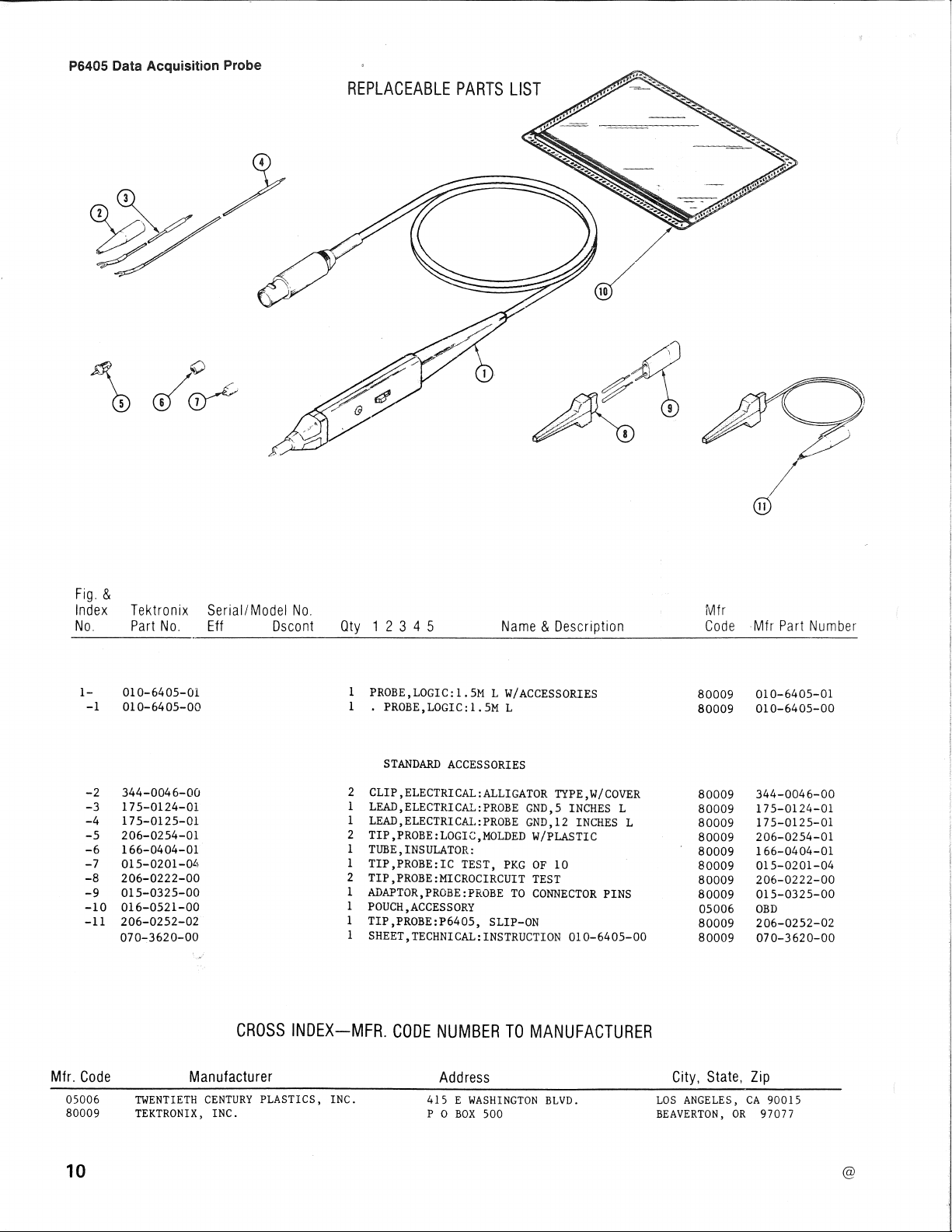
REPLACEABLE PARTS LIST
11
Fig. &
Index
No.
1-
-1
-2
-3
-4
-5
-6
-7
-8
-9
-10
-11
Tektronix
Part No.
010-6405-01
010-64 05-00
344-0046-00
175-0124-01
175-0125-01
206-0254-01
166-0404-01
015-0201-04
206-0222-00
015-0325-00
016-0521-00
206-0252-02
070-3620-00
Serial/ Model No.
Eff Os cont
Qty 1 2 3 4 5
1
PROBE,LOGIC:l.5M L W/ACCESSORIES
1
• PROBE,LOGIC:l.5M L
STANDARD ACCESSORIES
2
CLIP,ELECTRICAL:ALLIGATOR TYPE,W/COVER
1
LEAD,ELECTRICAL:PROBE GND,5 INCHES L
1
LEAD,ELECTRICAL:PROBE GND,12 INCHES L
2
TIP,PROBE:LOGIC,MOLDED W/PLASTIC
1
TUBE,INSULATOR:
1
TIP,PROBE:IC TEST, PKG OF 10
2
TIP,PROBE:MICROCIRCUIT TEST
1
ADAPTOR,PROBE:PROBE TO CONNECTOR PINS
1
POUCH,ACCESSORY
1
TIP,PROBE:P6405, SLIP-ON
1
SHEET,TECHNICAL:INSTRUCTION 010-6405-00
Name & Description
CROSS INDEX-MFR. CODE NUMBER TO MANUFACTURER
Mfr
Code Mfr Part Number
80009
80009
80009
80009 175-0124-01
80009
80009 206-0254-01
80009 166-0404-01
80009
80009
80009 015-0325-00
05006 OBD
80009
80009 070-3620-00
010-6405-01
010-6405-00
344-0046-00
175-0125-01
015-02 01-04
206-0222-00
206-0252-02
Mfr. Code Manufacturer
05006 TWENTIETH CENTURY PLASTICS, INC.
80009 TEKTRONIX, INC.
10
Address
415 E WASHINGTON BLVD.
PO BOX 500
City, State, Zip
LOS ANGELES, CA 90015
BEAVERTON, OR 97077
@
Page 11

n
u
RED
SHIELD
()
C
2,
-Z.O-
RI
9M
T
I
-,~---
Cl
8,ZpF
RZ
SOK
I O-OpF
cc
Si
/..
RED
n
11
11
u
5HELL
I
1
1
DATA
2
~
5OK RTN
3
!
RED_LITE
KTN_
'T'
I
I
P~405,DATA AC.QUISITION PROBE
BLUE
YELLOW
BROWN 6 1
Ai PROBE. BODY OJI.TA l>.C.QUISlilON B_Ol>.RD
4
5 I f'-E,SET LINE
I
GREEN LIT!:: RTN
+sv
3620-3
Page 12

 Loading...