

Page 1

xx
P6250 & P6251
500 MHz and 1 GHz High Voltage Differential Probes
ZZZ
Technical Reference
www.tektronix.com
071-2432-00
Page 2

Copyright © Tektronix. All rights reserved. Licensed software products are owned by Tektronix or its subsidiaries or suppliers, and are
protected by na
tional copyright laws and international treaty provisions.
Tektronix prod
previously published material. Specifications and price change privileges reserved.
TEKTRONIX and TEK are registered trademarks of Tektronix, Inc.
TekProbe is a trademark of Tektronix, Inc.
ucts are covered by U.S. and foreign patents, issued and pending. Information in this publication supersedes that in all
Contacting Tektronix
Tektronix, Inc.
14200 SW Karl Braun Drive
P.O. Box 500
Beaverton, OR 97077
USA
For product information, sales, service, and technical support:
In North America, call 1-800-833-9200.
Worldwide, visit www.tektronix.com to find contacts in your area.
Page 3

Table of Contents
General Safety Summary ............ . . . . . . . . . . . . . . . . ............. . . . . . . . . . . . . . . . . . .............. . . . . . . . . . . . . . . . . .............. . . . . . .. iii
Service Safet
Preface................................................................................................................................. v
Specifications .......................................................................................................................... 1
Warranted Char
Typical Characteristics ................................................................................................................ 3
Nominal Characteristics ............................................................................................................... 8
Probe Tip Adapt
Performance Verification ............................................................................................................. 15
Required Equipment ...... . . . . . . . . . . . . . . . .............. . . . . . . . . . . . . . . ............. . . . . . . . . . . . . . . . ................ . . . . . . . . . . . . . . . 16
Special Adapte
Preparation .. . . . . . . . . . . . . ................ . . . . . . . . . . . . . . . . . .................. . . . . . . . . . . . . . . . . . . ................ . . . . . . . . . . . . . . . . . .. 19
DC Attenuation Accuracy .. . . . . . . . . . . . . . ................... . . . . . . . . . . . . . . . . . . . .................... . . . . . . . . . . . . . . . . . . . ........... 20
Differential S
Analog Bandwidth........... . . . . . . . . . . . . . . . ............... . . . . . . . . . . . . . . . ............... . . . . . . . . . . . . . . . . .............. . . . . . . . . . . 24
Common Mode Rejection Ratio ................................................................................................ 27
Rise Time........................................................................................................................28
High Voltage Rise Time Check (Optional) . . .............. . . . . . . . . . . . . . ............. . . . . . . . . . . . . . . ............. . . . . . . . . . . . . . . .. 32
Alternate Verification Procedures.. . . . . . . . . . . . . . . ............... . . . . . . . . . . . . . . ................. . . . . . . . . . . . . . . ............... . . . . 37
Adjustment Proc
Equipment Required for Adjustment Procedure .. . . . . . . . . . . . . . . . .................... . . . . . . . . . . . . . . . . . . ................. . . . . . . . 43
Offset (Preliminary) .............................................................................................................44
Gain.............................................................................................................................. 45
Offset (Final)..................................................................................................................... 46
DC CMRR ....................................................................................................................... 46
AC CMRR ....................................................................................................................... 48
Maintenance .......................................................................................................................... 49
Inspection and Cleaning . . . . . . . . . . . . . . . . . . ............. . . . . . . . . . . . . . . . . . .............. . . . . . . . . . . . . . . . . ............... . . . . . . . . . . . 49
Replacement Part
Preparation for Shipment ... . . . . . . . . . . . . . . . . .............. . . . . . . . . . . . . . . ................. . . . . . . . . . . . . . . . .............. . . . . . . . . . . 49
y Summary .............................................................................................................. iv
acteristics............................................................................................................. 2
er Specifications ..................................................................................................... 9
rs ................................................................................................................ 17
ignal Range . . . . . . . ............ . . . . . . . . . . . . . ............. . . . . . . . . . . . . ............. . . . . . . . . . . . . . .............. . . . . . . 22
edures . . . .......... . . . . . . . . . . . . ............ . . . . . . . . . . . .............. . . . . . . . . . . . . ........... . . . . . . . . . . . . ............ . 42
s.............................................................................................................. 49
Table of Content
s
P6250 & P6251 Technical Reference i
Page 4

Table of Content
s
ii P6250 & P6251 Technical Reference
Page 5

General Safety S
ummary
General Safet
Review the following safety precautions to avoid injury and prevent damage to this product or any products connected to it.
To avoid potential hazards, use this product only as specified.
Only qualified personnel should perform service procedures.
While using this product, you may need to access other parts of a larger system. Read the safety sections of the other
component manuals for warnings and cautions related to operating the system.
To Avoid Fire or Personal Injury
Connect and Disconnect Properly. Do not connect or disconnect probes or test leads while they are connected
to a voltage s
Ground the Pro
To avoid electric shock, the grounding conductor must be connected to earth ground. Before making connections to the input
or output terminals of the product, ensure that the product is properly grounded.
Observe All Terminal Ratings. To avoid fire or shock hazard, observe all ratings and markings on the product. Consult
the product m
Connect the p
Do not apply a
ource.
anual for further ratings information before making connections to the product.
robe reference lead to earth ground only.
potential to any terminal, including the common terminal, that exceeds the maximum rating of that terminal.
y Summary
duct.
This product is indirectly grounded through the grounding conductor of the mainframe power cord.
Do Not Operat
Do Not Operat
qualified service personnel.
e Without Covers.
e With Suspected Failures.
Do not operate this product with covers or panels removed.
If you suspect that there is damage to this product, have it inspected by
Avoid Exposed Circuitry. Do not touch exposed connections and components when power is present.
Do Not Operate in Wet/Damp Conditions.
Do Not Operate in an Explosive Atmosphere.
Keep Product Surfaces Clean and Dry.
P6250 & P6251 Technical Reference iii
Page 6

Service Safety S
TermsinthisManual
These terms may appear in this manual:
WARNING. Warning statements identify conditions or practices that could result in injury or loss of life.
CAUTION. Caution statements identify conditions or practices that could result in damage to this product or other property.
Symbols and Terms on the Product
These terms may appear on the product:
DANGER indicates an injury hazard immediately accessible as you read the marking.
WARNING indicates an injury hazard not immediately accessible as you read the marking.
CAUTION indicates a hazard to property including the product.
The following symbol(s) may appear on the product:
ummary
Service Safety Summary
Only qualified personnel should perform service procedures. Read this Service Safety Summary and the General Safety
Summary before performing any service procedures.
Do Not Service Alone. Do not perform internal service or adjustments of this product unless another person capable of
rendering first a id and resuscitation is present.
Disconnect Power. To a v o
mains power.
Use Care When Servicing With Power On. Dangerous voltages or currents may exist in this product. Disconnect
power, remove battery (if applicable), and disconnect test leads before removing protective panels, soldering, or replacing
components.
To avoid electric shock, do not touch exposed connections.
id electric shock, switch off the instrument power, then disconnect the power cord from the
iv P6250 & P6251 Technical Reference
Page 7

Preface
This is the Technical Reference for the P6250 & P6251 differential probes. This manual provides specifications and
performance verification procedures for the probes.
Preface
P6250 & P6251 Technical Reference v
Page 8

Preface
vi P6250 & P6251 Technical Reference
Page 9

Specifications
Specification
The specifications in the following Tables apply to a P6250 or P6251 differential probe installed on a Tektronix TDS5000B
oscilloscope. When the probe is used with another oscilloscope, the oscilloscope must have an input impedance of 50 Ω
and a bandwidth of 1 GHz. The probe must have a warm-up period of at least 20 minutes and be in an environment that
does not exceed the limits described. (See Table 1.) The probe calibration should be run on the host instrument before
verifying the warranted probe specifications. Specifications for the P6250 and P6251 differential probes fall into three
categories: warranted, typical, and nominal characteristics.
s
P6250 & P6251 Technical Reference 1
Page 10

Warranted Chara
cteristics
Warranted Cha
Warranted characteristics describe guaranteed performance within tolerance limits or certain type-tested requirements. (See
Table 1.) Warranted characteristics that have checks in the Performance Verification section are marked with the
Table 1: Warranted electrical characteristics
Specification P6250 P6251
Differential signal range (DC coupled)
Common-mode signal range (DC coupled)
Maximum nondestructive input voltage
between signal and common of the same
channel
DC attenuatio
Bandwidth (4.25 V range (÷ 5), probe
only)
Rise time, 4.25 V range (÷ 5), probe
only (10–90%,
Common-mode rejection ratio
Temperature
Humidity
1
See warning that follows.
n accuracy
+20°Cto+30°C)
racteristics
±4.25 V
±42 V
±35V
±100 V
(DC + peak AC)
(DC + peak AC)
(DC + peak AC)
(DC + peak AC)
;3V
;30V
;25V
RMS
RMS
RMS
±4.25 V
±42 V
±35V
±100 V
(DC + peak AC)
(DC + peak AC)
(DC + peak AC)
(DC + peak AC)
;3V
;30V
;25V
RMS
RMS
RMS
±5% of input (both ranges) ±5% of input (both ranges)
DC to ≥500 MHz DC to ≥1GHz
≤700 ps ≤350 ps
42 V range (÷ 5
>55 dB at 30 kHz
>50dBat1MHz
>18 dB at 250 MH
Operating: 0
0):
z
to +40 °C (32 °F to +104 °F)
42 V range (÷ 5
>55dBat30kHz
>50 dB at 1 MHz
>18 dB at 250 MH
Nonoperating: –55 to +75 °C (–67 °F to –167 °F)
1
0):
z
Operating: 0-90% RH, tested at + 30 to +40 °C
Nonoperating: 0-90% RH, tested at +30 to +60 °C
symbol.
WARNING. To avoid a burn hazard at high ambient temperatures, do not touch the probe with bare hands at nonoperating
temperatures above + 50 °C .
2 P6250 & P6251 Technical Reference
Page 11

Typical Charact
eristics
Typical Chara
Typical characteristics (Tables 2 and 3) describe typical but not guaranteed performance for both probes.
Table 2: Typical electrical characteristics
Differential input resistance, DC coupled 1 MΩ
Common mode input resistance 500 kΩ
Differential input capacitance
Common-mode input capacitance
Harmonic distortion
Offset accuracy ±10 mV ±2% of offset setting at 20 to +30 ° C (68 °F to
Differential offset range ±4.25 V (÷ 5), ±42 V (÷ 50)
Common mode rejection ratio (See Figure 5 on page 5.) (See Figure 6 on page 6.)
System noise
Referred to probe output
Input impedance
Bandwidth limit ≥ –3 dB at 5 MHz
Propagation delay
cteristics
<1.0 pF at 1 MHz
<2.0 pF per side at 1 MHz
≤1.5% measured using 495 mV
100 MHz
+86 °F)
<2.0 mV
(÷ 50))
(See Figure 7 on page 6.)
6.5 ns from probe tip to output
(4.25 V range (÷ 5)), <1.0 mV
RMS
RMS
(or 1.4 V
RMS
) output at
P-P
(42 V range
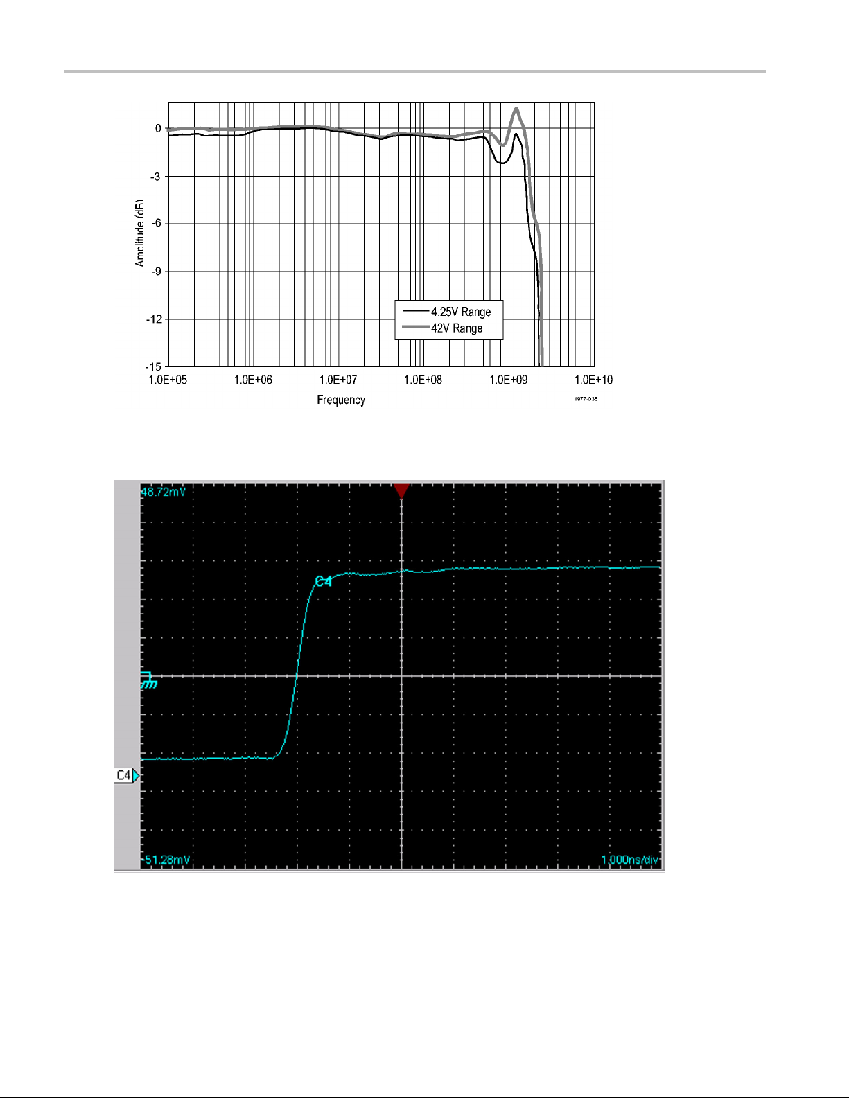
1: Typical bandwidth (P6250)
Figure
P6250 & P6251 Technical Reference 3
Page 12
Typical Charact
Figure 2: Typical bandwidth (P6251)
eristics
Figure 3: Typical rise time (P6250)
4 P6250 & P6251 Technical Reference
Page 13
Typical Charact
eristics
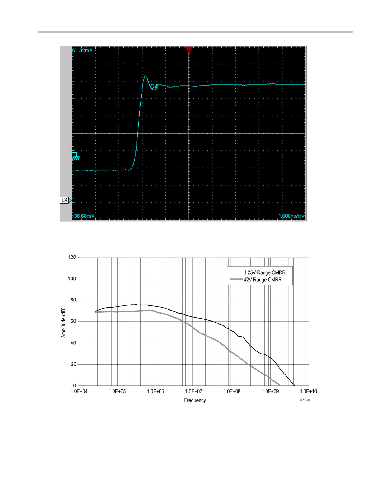
Figure 4: Typical rise time (P6251)
Figure 5: Typical Common-Mode Rejection Ratio (P6250)
P6250 & P6251 Technical Reference 5
Page 14
Typical Charact
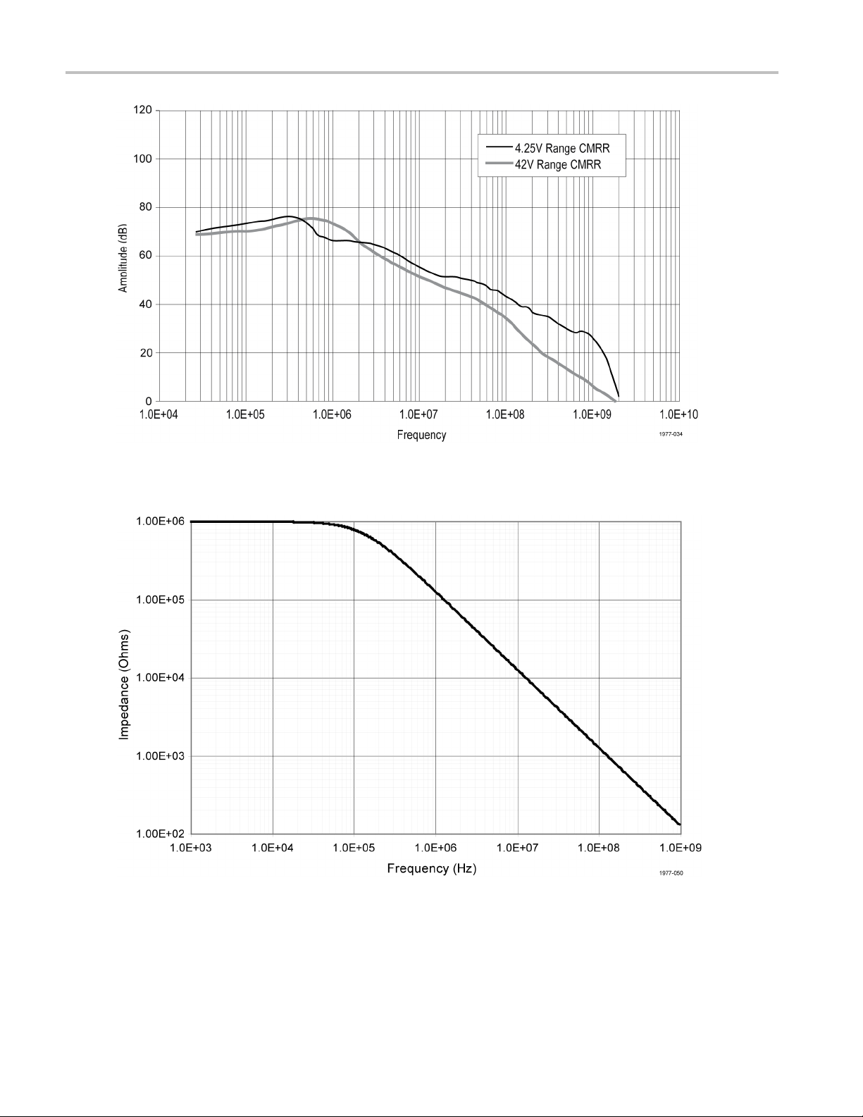
Figure 6: Typical Common-Mode Rejection Ratio (P6251)
eristics
Figure 7: Typical input impedance versus frequency
6 P6250 & P6251 Technical Reference
Page 15

Table 3: Typical mechanical characteristics
Typical Charact
eristics
Dimensions, input connection
Dimensions, control box
Dimensions, probe head
Dimensions, output cable
Unit weight (p
robe only)
0.63 mm (0.025 i
82 mm × 41 mm × 26
86 mm × 11 mm × 6.
1.22 m (48 in)
163 g (5.24 oz)
n) square pin on 2.54 mm (0.100 in) centers
mm (3.2 in × 1.6 in × 1 .0 in)
3mm(3.4in×0.45in×0.25in)
P6250 & P6251 Technical Reference 7
Page 16

Nominal Charact
eristics
Nominal Chara
Nominal characteristics (Table 4) describe guaranteed traits, but the traits do not have tolerance limits.
Table 4: Nominal electrical characteristics
Input configuration Differential (two inputs, + and - ), with case ground
Output coupling DC coupling
Voltage ranges 4.25 V and 42 V
Termination
cteristics
Terminate output into 50 Ω
8 P6250 & P6251 Technical Reference
Page 17

Probe Tip Adapte
r Specifications
Probe Tip Adap
This section describes the characteristics of the adapters that are included in your accessory kit. The adapters are listed
in order of performance, beginning with the fastest. You will obtain the best probe performance by connecting the probe
directly to square pins on your circuit. However, as test points are not always as convenient, these adapters m ake taking
measurements easier while maintaining the best signal fidelity.
NOTE. All adapter specifications are typical unless otherwise indicated.
Straight Pins
Tektr o nix p a
Bandwidth: >
10/90 Rise ti
Best overall
rt number: 016-1891-xx
1.0 GHz
me: <350 ps
signal fidelity of the available adapters.
ter Specifications
P6250 & P6251 Technical Reference 9
Page 18

Probe Tip Adapte
Longhorn Adapter
Tektronix part number: 016-1780-xx
Bandwidth: >1.0 GHz
10/90 Rise time: <350 ps
This adapter has sharp, adjustable pins that can span up to 0.35 inch apart. They are useful for probing small circuit
board features such as vias and narrow traces.
rSpecifications
10 P6250 & P6251 Technical Reference
Page 19

Probe Tip Adapte
r Specifications
1” Solder Down Adapter
Tektronix part number: 196-3504-xx
Bandwidth: >820 MHz
10/90 Rise time: <430 ps
Use this adapter to provide easy access to test points that you frequently check, or that may be difficult to probe with
other methods.
P6250 & P6251 Technical Reference 11
Page 20

Probe Tip Adapte
3” Solder Down Adapter
Tektronix part number: 196-3505-xx
Bandwidth: >550 MHz
10/90 Rise time: <635 ps
Use this adapter on test points that you frequently check that do not have square pins or other convenient connections.
Solder the leads to your test points, spaced up to 5.5 inches apart.
CAUTION. To prevent short circuits, solder and dress the adapter leads carefully, and make sure that the adapter pins
do not touch other conductors when the adapter is not connected to the probe.
rSpecifications
12 P6250 & P6251 Technical Reference
Page 21

Probe Tip Adapte
r Specifications
Y-Lead Adapter
Tektronix part number: 196-3434-xx
Usable Bandwidth: <250 MHz
Calculated rise time: 1.4 ns
Use this adapter for DC and low-frequency measurements. The socket ends plug onto square pins, component leads, and
the MicroCKT test tip adapters included with the probe.
P6250 & P6251 Technical Reference 13
Page 22

Probe Tip Adapte
MicroCKT Test Tip Adapter
Tektronix part number: 206-0569-xx
Usable Bandwidth: <100 MHz
Calculated rise time: 3.5 ns
Use the microCKT test tip adapters with the Y-lead adapters. Due to the length of these adapters, they are only
recommended for DC and low-frequency measurements.
rSpecifications
14 P6250 & P6251 Technical Reference
Page 23

Performance Ver
ification
Performance V
Use the following procedures to verify the warranted specifications of the P6250 and P6251 Differential Probes. Before
beginning these procedures, photocopy the test record and use it to record the performance test results. (See Table 7 on
page 35.) The recommended calibration interval is one year.
These procedures test the following specifications:
DC attenuation accuracy
Differential signal range
Analog bandwidth*
Common mode rejection ratio*
Rise time
* These tests require a network analyzer. Alternate test procedures that use a synthesizer and spectrum analyzer are
provided in the Appendix.
Optional procedures are provided to test the following typical specifications:
High voltage rise time
erification
P6250 & P6251 Technical Reference 15
Page 24

Performance Ver
ification
Required Equipment
Table 5 lists the equipment required to perform the performance verification procedure. The types and quantities of
connectors may vary depending on the specific equipment you use.
NOTE. The procedures in this section require a network analyzer to perform the analog bandwidth and CMRR tests.
Alternative procedures that do not require a network analyzer are included in this manual.
Table 5: Test equipment
Description Minimum requirements Example product
Network analyzer
Sampling oscilloscope Tektronix TDS8000 series
Sampling Module
Power Supply
BNC-to-probe tip adapter Optional probe accessory
BNC-to-SMA Female adapter (2)
Calibrated DC voltage source (2) Adjustable from 0 V to ≥42 V. Outputs
DMM (2 required) DC Accuracy ≥ 0.5% on range to
BNC cables (2) 50 Ω,42inch
SMA cable (2) 50 Ω,28inch
Banana-to-banana patch cords (3)
Dual-male-banana-to-female BNC
adapter (3)
BNC male to dual binding post
adapter (2)
Precision inline BNC terminator 50 Ω ±0.1%
Y-lead
MicroCKT test tip (2) Standard accessory included w/probe
0.025” square pins (3) Approximately 3/4 inch long, smooth,
100 kHz to ≥2 GHz, w ith cables and
adapters to BNC male and SMA male
TDR output; 250 mV step, <100 ps rise
time
As per description Tektronix 015-0572-xx
must be isolated from earth ground.
measure 42 V, averaging mode.
2red
1black
As per description Tektronix 103-0090-xx
As per description Tektronix 103-0035-xx
Standard accessory included w/probe
gold plated.
Hewlett Packard 8753D
oscilloscope
Tektronix 80E04
Tektronix 1103 power supply
Tektronix 067-1734-xx
Keithley 2400
Fluke 187
Tektronix 012-0057-xx
Tektronix 012-0649-xx
Tektronix 012-0031-xx
Tektronix 012-0039-xx
Tektronix 011-0129-xx
Tektronix 196-3434-xx
Tektronix 206-0569-xx
Note: The equipment listed below is for the optional 42 V rise time test.
High Voltage Pulse Generator
Probe calibration fixture Optional probe accessory
Termination
16 P6250 & P6251 Technical Reference
42 V, 300 ps rise time
50 W, 50 Ω, SMA connector
Picosecond Labs 2600C
Tektronix 067-0419-xx
JFW 50T 334–1.0
Page 25

Performance Ver
ification
Attenuator
Spring-loaded
probe tip pins
Special Adapters
Some of the adapters used in these procedures are available only from Tektronix. These adapters are described on
the following pages.
1103 Power Supply
The 1103 powe
access to the probe output signal for performance verification measurements.
1. BNC connector for probe output measurements
2. BNC input connections
r supply is used to power the probe under test. BNC connectors on the front of the power supply provides
100 X, 50 W, BNC c
P7260 probe accessory Tektronix 016-1917-xx
onnector
Aeroflex 60B50W
-40dB
P6250 & P6251 Technical Reference 17
Page 26

Performance Ver
BNC-to-Probe Tip Adapter
The BNC-to-probe tip adapter, Tektronix part number 067-1734-xx, provides connections for signal sources and probe test
points. (See Figure 8.) The adapter breaks out the signal input on the BNC connector to pairs of square pins, one each for
common-mode and differential-mode connections.
1. BNC c onnector for input signals
2. Differential Mode (DM) square-pin pair
3. Common Mode (CM) square-pin pair (with ground pin)
Figure 8: BNC-to-prob e tip adapter
ification
Probe Calibration Fixture (Optional)
The Probe Calibration Fixture, Tektronix part number 067-0419-xx, prov
the probe at the 42 V range (÷ 50) (See Figure 9.) This check is not required to complete the performance verification of the
probe, but is provided for users who want to check the probe rise time at the higher voltage range.
1. SMA connectors for input/output signals and terminations
2. Common Mode (CM) test points
3. Differential Mode (DM) test points
ides a means to check the rise time specification of
Figure 9: Probe calibration fixture connections
18 P6250 & P6251 Technical Reference
Page 27

Preparation
CAUTION. To prevent damage to the 80E04 sampling head, plug in the sampling head and then power on the TDS8000
oscilloscope
Prepare the equipment as follows:
1. Connect the 80E04 sampling head to channel 1 of the sampling oscilloscope and then power on the TDS8000
oscilloscope.
2. Plug in and power on all test equipment. (See Table 5 on page 16.)
3. Connect the probe to channel 1 of the 1103 power supply.
4. Allow the probe and test equipment to warm up for 20 minutes at an ambient temperature of 20 °C to 30 °C.
5. Photocopy the test record and use it to record the test results. (See Table 7 on page 35.)
Perform the veri fication procedures in order.
Performance Ver
.
ification
P6250 & P6251 Technical Reference 19
Page 28

Performance Ver
ification
DC Attenuation Accuracy
This test checks the probe gain by m easuring known voltages with a multimeter. The probe is then used to measure the
same voltages, and then a comparison calculation is made.
Preparation
1. Press the VAR/
0v button to the off position on the 1103 power supply (the button is not lighted).
2. Set the probe to the 42 V range (÷ 50), DC reject off, and full bandwidth.
3. Connect the MicroCKT test tips to the DC source. Observe proper polarity: red to (+), black to (–).
4. Connect a DMM to the DC source and set the DMM to DC volts.
5. Connect the BNC cable to the output connector of channel 1 on the 1103 power supply.
6. Connect the Precision BNC terminator (011-0129-XX) to the second DMM using a BNC-to-dual banana adapter .
7. Connect the other end of the BNC cable to the Precision BNC terminator.
Verifi cation
42 V Range (÷ 50).
8. Set the input voltage on the DC source to approximately 40 V. Record the actual voltage as Vin1.
9. Record the output voltage as V
10. Set the input voltage on the DC source to approximately 20 V. Record the actual voltage as V
11. Record the output voltage as V
12. Set the input voltage on the DC source to approximately 5 V. Record the actual voltage as V
13. Record the output voltage as V
20 P6250 & P6251 Technical Reference
1.
out
2.
in
2.
out
3.
in
3.
out
Page 29

Performance Ver
ification
14. Calculate the attenuation twice, using the values from the measurements as follows: (Vin1-Vin2) ÷ (V
)÷(V
2-V
and (V
2-Vin3
in
15. Verify that the
out
attenuation is in the range of 49 to 51. Record the results in the test record.
3).
out
out
1-V
2)
out
4.25 V Range (÷ 5).
16. Set the input voltage on the DC source to approximately 4.2 V ±50 mV. Record the actual voltage as Vin1.
17. Change the probe voltage range to 4.25 V (÷ 5).
18. Record the output voltage as V
19. Set the input voltage on the DC source to 2 V, and record the actual voltage as V
20. Record the output voltage as V
21. S et the input voltage on the DC source to approximately 0.5 V. Record the actual voltage as V
22. Record the output voltage as V
23. Calculate the attenuation twice, using the formulas from the previous test. Refer to step 14.
24. Verify that the attenuation is in the range of 4.9 to 5.1. Record the results in the test record.
25. Slide the DC Reject switch on the probe to turn DC reject on.
26. Verify that the output returns to approximately 0 volts. (This is a functional check; there is no specified performance limit.)
1.
out
2.
in
2.
out
3.
in
3.
out
27. Slide the DC Reject switch on the probe to turn DC reject off.
28. Keep the output connections for the next procedure.
P6250 & P6251 Technical Reference 21
Page 30

Performance Ver
ification
Differential Signal Range
This procedure directly verifies the differential signal range and indirectly verifies the common-mode signal range. This
procedure uses the setup from the previous test.
Verifi cation
42 V Range (÷ 50).
1. Set the probe to the 42 V range (÷ 50), DC reject off, and full bandwidth.
2. Set the input voltage on the DC source to 0 V, and verify that it is 0 V with the multimeter.
3. Measure the probe output voltage as V
. You will use this offset voltage to acquire accurate results in the calculations
offset
below.
4. Set the input voltage on the D C source to 42 V ±100 mV, and record the actual voltage as Vin.
5. Measure and record the output voltage as V
.
out
6. Calculate attenuation as |V
in
÷(V
out–Voffset
)|.
7. Verify that the attenuation is in the range of 47.5 to 52.5. Record the results in the test record.
8. Reverse the Y-lead connection on the probe to reve rse the polarity of your following measurements.
9. Measure and record the output voltage as V
.
out
10. Calculate attenuation using the formula in step 6.
11. Verify that the attenuation is in the range of 47.5 to 52.5. Record the results in the test record.
4.25 V Range (÷ 5).
12. Reverse the Y-lead connection on the probe (back to: red to +, black to –).
13. Set the DC source to 4.25 V ±10 mV, and record the actual voltage as V
22 P6250 & P6251 Technical Reference
.
in
Page 31

14. Set the probe to the 4.25 V range (÷ 5).
Performance Ver
ification
15. Measure and record the output voltage as V
.
out
16. Calculate attenuation using the formula in step 6.
17. Verify that the attenuation is in the range of 4.75 to 5.25. Record the results in the test record.
18. Reverse the Y-lead connection on the probe to reverse the polarity of your following measurements.
19. Measure and record the output voltage as V
.
out
20. Calculate attenuation using the formula in step 6.
21. Verify that the attenuation is in the range of 4.75 to 5.25. Record the results in the test record.
22. Disconnect the probe from the test setup and connect it to any oscilloscope channel to keep the probe at operating
temperature.
P6250 & P6251 Technical Reference 23
Page 32

Performance Ver
ification
Analog Bandwidth
The following steps prepare the network analyzer for measuring bandwidth and CMRR. The actual settings may vary with
different models of network analyzer. Refer to the user documentation supplied w ith the network analyzer for details
on performing these steps.
NOTE. An alternative procedure for testing the analog bandwidth and CMRR without a network analyzer is available.
Preparation
The 1103 power supply can operate two probes. To keep the probe warmed up, move it to channel 2 of the 1103 while
normalizing
channel 1.
1. Set the netwo
2. Set the displ
3. Set the start
4. Set the test p
5. Set the IF ban
6. Attach the ca
if necessary.
7. Attach the cable from port 2 to the 1103 channel 1 output connector (conventional BNC). Use a male BNC adapter
if necessary.
8. Normalize the network analyzer to remove the loss through channel 1 of the 1103 power supply.
rk analyzer to measure transmission loss, S
ay format to log magnitude, 1 dB/div, reference value –14 dB, and linear frequency.
frequency to ≈ 30 kHz (or the lowest frequency on the network analyzer) and the stop frequency to ≈ 2GHz.
ort power to +10 dBm .
dwidth to 10 kHz.
ble from port 1 to the 1103 channel 1 input connector (TekProbe connector). Use a male BNC adapter
. Attach cables to both ports.
21
24 P6250 & P6251 Technical Reference
Page 33

Performance Ver
Verification
4.25 V Range (÷ 5).
NOTE. Do not remove the cable end that is connected to the network analyzer. Connect the cable to the BNC-to-probe tip
adapter.
ification
1. Disconnect t
2. Move the prob
3. Set the probe f
4. Connect the p
5. The setup sho
he port 1 cable from the 1103 channel 1 input connector and connect to the BNC-to-probe tip adapter.
e from the 1103 channel 2 to channel 1 input connector.
or ÷ 5 attenuation, full bandwidth, DC reject off.
robe input to the DM pins on the BNC-to-probe-tip adapter. Polarity is unimportant.
uld now appear as shown below.
6. Read the amplitude at 500 MHz for the P6250 or 1 GHz for the P6251. The use of the marker function, (if equipped), will
simplify resolving the bandwidth.
7. Verify that the amplitude is greater than –17 dB. (Subtracting the –14 dB of probe attenuation in the 4.25 V range (÷ 5)
from the –17 dB target value yields the 3 dB limit.) Record the results in the test record.
P6250 & P6251 Technical Reference 25
Page 34

Performance Ver
42 V Range (÷ 50).
8. Set the probe to the 42 V range (÷ 50).
9. Change the reference value on the network analyzer to keep the plot on screen (–34 dB).
10. Using the marker (if equipped), measure the output amplitude at 500 MHz for the P6250 or 1 GHz for the P6251.
11. Verify that the amplitude is greater than –37 dB. (Subtracting the –34 dB of probe attenuation in the 42 V range from the
–37 dB target value yields the –3 dB limit.) Record the results in the test record.
12. Retain the setup for the next test.
ification
26 P6250 & P6251 Technical Reference
Page 35

Common Mode Rejection Ratio
If verification of analog bandwidth was not performed, or the calibration of the network analyzer has been altered, perform the
calibration and normalization steps in the Preparation section of the Analog Bandwidth verification.
In this test, you first plot the differential mode gain, and then the common mode gain. Next, using the math function on the
network analyzer, you create a plot that represents the reciprocal of the CMRR.
Verification
42 V Range (÷ 50).
Performance Ver
ification
1. Set the refer
2. Verify that t
3. Connect the p
4. Set the probe
5. The plot that
6. Disconnect t
sure to connect the probe ground socket to the long ground pin on the fixture.
7. The plot that is displayed represents the common mode gain of the probe. You may need to adjust the reference
level and scale to view the plot.
8. Use the math function of the network analyzer to divide this plot by the differential plot that you saved in step 5. The
resulting pl
of the magnitude.
9. Measure the CMRR at 30 kHz, 1 MHz, and 250 MHz. Analyzers with marker capability can do this directly by setting
the marker intercepts at 30 kHz, 1 MHz, and 250 MHz. If necessary, turn on the network analyzer Average mode
with 16 aver
10. Verify that
ence value of the network analyzer to –34 dB and position the reference near the top of the screen.
he test port power is set to +10 dB m.
robe input to the DM pins on the BNC-to-probe tip adapter. Polarity is unimportant.
to the 42 V range (÷ 50), full bandwidth, and DC reject off.
is displayed represents the differential mode gain of the probe. Save this plot to the instrument memory.
he probe input from the DM pins and connect it to the CM pins on the BNC-to-probe tip adapter. Make
ot is the reciprocal of the common mode rejection ratio. The CMRR can be read by inverting the sign
ages to stabilize the reading.
the CMRR is greater than the values listed in the following, and record the results in the test record.
Table 6: CMRR limits
Frequency 42 V Range (÷
30 kHz ≥55 dB
1MHz ≥50 dB
250 MHz ≥18 dB
50) CMRR
11. Disconnect the equipment.
P6250 & P6251 Technical Reference 27
Page 36

Performance Ver
Rise Time
This procedure verifies that the probe meets the warranted rise time specification of the 4.25 V range (÷ 5). Two rise times
are measured; the test system alone, and then the test system with the probe included. The probe rise time is calculated
using the two measurements.
This test uses the 80E04 as a fast rise time signal source. The second channel of the 80E04 sampling head is used to take
the measurements. Although the following procedure assigns the TDR and measurement functions to specific oscilloscope
channels, any channels can be used. However, the TDR function is only available on 80E04 sampling heads.
CAUTION. To prevent damage to the SMA connectors, use care when working with SMA connectors: support equipment to
avoid mechanical strain on the connectors, and when tightening connections, use a torque wrench to 7.5 in-lbs.
Test System Rise Time
1. Connect the 80E04 sampling head to Channel 1 of the sampling oscilloscope.
2. Connect SMA cables to Channels 1 and 2 on the sampling head.
3. Connect the SMA cable from Channel 1 to the probe input BNC connector on the 1103 power supply using an SMA-BNC
adapter.
ification
4. Connect the SMA cabl
1103 power supply.
5. Turn on Channel 2 and set the vertical scale to 50 mV/div.
e from Channel 2 to an SMA-to-BNC Adapter, and then to the output BNC connector on the
28 P6250 & P6251 Technical Reference
Page 37

Performance Ver
6. Set the Channel 1 sampling head to TDR mode: press the SETUP DIALOGS button and select the TDR tab. Refer to
the following i
llustration.
ification
7. Set the Channel
8. Set the Preset o
TDR Preset sets
1(C1) Polarity to positive (rising).
f Channel 1 on.
Internal Clock in the Trigger menu, turns on the TDR Step in the TDR Setups menu, turns on the
channel and selects the acquisition Units in the TDR Setups menu, and sets the horizontal scale, position, and reference.
The sampling module will turn on a red light next to the SELECT channel button, indicating that TDR is activated for
that channel.
9. Turn off the display for Channel 1 so that only Channel 2 is shown on screen.
10. Adjust the oscilloscope vertical positioning to center the signal on screen.
11. S et the oscilloscope horizontal scale to 200 ps/div and center the waveform.
12. Use the oscilloscope measurement capability to display rise time.
Increase the stability of the pulse edge measurement by using a veraging, if available. Rise time is determined from
the 10% and 90% amplitude points on the waveform.
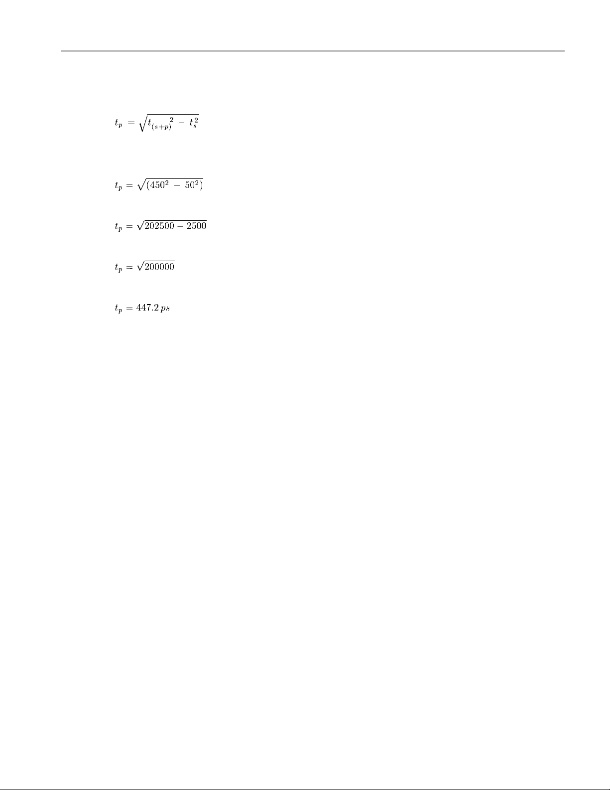
13. Recordtherisetimeast
. This measurement represents the rise time of the test system without the probe.
s
The following steps instruct you to assemble the test setup that includes the probe. The system and probe rise time
hat you measured in step 12 is used to calculate the probe rise time (tp) in step 14.
(ts+p) t
P6250 & P6251 Technical Reference 29
Page 38

Performance Ver
Test System and Probe Rise Time
14. Disconnect the SMA cable and BNC adapter from the Channel 1 input of the 1103 power supply.
15. Connect the SMA cable to the BNC-to-probe tip adapter.
16. Connect the probe to the 1103 power supply channel 1 input and set the attenuation to ÷ 5.
17. Turn off the offset control on channel 1 of the 1103 power supply.
ification
18. Connect the probe to the DM test points on the BNC-to-probe tip adapter.
19. Adjust the oscilloscope vertical scale to 20 mV/div, averaging on.
20. Adjust the oscilloscope horizontal positioning to place the rising edge of the signal so that it crosses the second vertical
and cent
21. Use the m
Increas
er horizontal graticule lines.
easurement capability of the sampling oscilloscope to display rise time.
e the stability of the pulse edge measurement by using averaging, if available. Rise time is determined from
the 10% and 90% amplitude points on the waveform.
22. Record the rise time as t
s+p
.
30 P6250 & P6251 Technical Reference
Page 39
Performance Ver
ification
23. Using the test system rise time (ts) that you measured in step 12, and the test system and probe rise time (t
measured in ste
p 21, calculate the probe-only rise time using the formula shown.
Example:
24. R ecord the calcu
This completes t
lated probe rise time on the test record.
he performance verification. An optional rise time check for the 42 V range (÷ 50) follows.
) that you
s+p
P6250 & P6251 Technical Reference 31
Page 40

Performance Ver
ification
High Voltage Rise Time Check (Optional)
Use the following optional test to check the probe rise time on the 42 V range (÷ 50) setting.
WARNING. Burn hazard exists. The 50 W termination used in this test becomes hot if the duty cycle of the pulse generator
is higher than 10%. Use caution when locating the termination in your test setup.
Test System Rise Time
1. Connect the 80E04 sampling head to the sampling oscilloscope.
2. Connect an SMA cable to Channel 2 on the sampling head.
3. Connect an SMA to BNC adapter to the other end of the SMA cable.
4. Connect the SMA c able from Channel 2 to the output of the 1103 power supply.
5. Connect an SMA-to-BNC adapter to one of the SMA connectors on the probe calibration fixture.
6. Connect one end of the high power attenuator to the BNC adapter on the probe calibration fixture.
7. Connect the other end of the high power attenuator to the BNC connector on the 1103 power supply (Channel 2). It is
recommended that you
support the probe calibration fixture as shown below, when it is attached to the 1103 power supply.
32 P6250 & P6251 Technical Reference
Page 41

Performance Ver
8. Connect a short SMA cable from the other SMA connector on the probe calibration fixture to the high voltage output
connector on th
e pulse generator.
ification
9. Connect the tri
gger out from the pulse generator to the trigger in on the sampling oscilloscope.
WARNING. To reduce the risk of electric shock, do not exceed 42 Vpk on the pulse generator. Use caution when making
measurements.
10. Turn on Channel 2 and se
11. Turn on the pulse gener
12. Adjust the oscillosc
t the vertical scale to 100 mV/div.
ator and set the output to approximately 40 V.
ope horizontal and vertical position controls to display a rise time signal similar to that shown in the
setup figure.
13. Set the oscilloscope horizontal scale to 500 ps/div and center the waveform.
14. Use the oscilloscope measurement capability to display rise time.
Increase the stability of the pulse edge measurement by using a veraging, if available. Rise time is determined from
the 10% and 90% amplitude points on the waveform.
15. Record the rise time as t
Test System and Rise
.
s
Time
16. Disconnect the SMA-to-BNC adapter from the BNC connector on the 1103 power supply.
17. Connect the BNC end of the adapter to the 50 W termination.
18. Connect the probe to the 1103 power supply.
19. Connect two spring-loaded probe tips to the probe head sockets.
20. Slide the switch on the probe to the 42 V range (÷ 50).
21. Touch the probe tips to the DM pads on the probe calibration adapter and measure the rise time.
22. Perform the calculation with the two measured rise times and the formula below. A typical result is about 330 ps.
23. Record the measured rise time of the system and probe as t
. This measurement at the 42 V range (÷ 50) is typically
s+p
about 400 ps.
This completes the performance verification procedures.
P6250 & P6251 Technical Reference 33
Page 42

Performance Ver
ification
34 P6250 & P6251 Technical Reference
Page 43

Table 7: Test Record
Performance Ver
ification
Probe Model/Se
Temperature: _____________ RH % : _____________
Date of Calibration: _____________Technician: _____________
Performance test Minimum Measured/Calculated Maximum
DC attenuation accuracy
42 V range (÷ 50
4.25 V range (÷ 5)
Differential signal range
42 V range (÷ 50)
with connecti
4.25 V range (÷ 5)
with connections reversed
Rise Time
4.25 V range (÷ 5)
P6250 at 500 MHz
P6251 at 1 GHz
Analog bandwid
P6250 at 500 MHz
P6251 at 1 GHz
4.25 V range (÷ 5)
42 V range (÷ 50)
CMRR
42 V range (÷ 50)
30 kHz
1MHz
250 MHz
rial Number: _____________ Certificate Number: _____________
)
ons reversed
th
49
4.9
47.5
47.5
4.75
4.75
≤700 ps
≤350 ps
-3dB
-3dB
55 dB
50 dB
18 dB
_____________
_____________
_____________
_____________
_____________
_____________
_____________
_____________
_____________
_____________
_____________
_____________
_____________
51
5.1
52.5
52.5
5.25
5.25
N/A
N/A
N/A
N/A
N/A
N/A
N/A
P6250 & P6251 Technical Reference 35
Page 44

Performance Ver
ification
36 P6250 & P6251 Technical Reference
Page 45

Alternate Verification Procedures
This section contains alternate procedures for verifying the following specifications:
Analog bandwidth
Common mode rejection ratio
Use these alternate procedures only if you cannot obtain a network analyzer.
Equipment Required for Performance Verification
Table 8: Test equipment
Description Minimum requirements Example product
Sine wave generator (preferably a
synthesizer)
Spectrum analyzer DC to 3 GHz (dynamic range ≥100
Power supply Tektronix 1103 power supply
BNC-to-Type N coaxial adapters (2) Type N male-to-BNC female
BNC cables (2) 50 Ω,18inch
Probe tip adapter BNC-to-probe tip Optional probe accessory
0 dBm to 20 dBm from 1 MHz to
1GHz.
dBm at 1 MHz)
Performance Ver
Fluke 6061A
Advantest RSA 3303A
Tektronix 103-0045-xx
Tektronix 012-0076-xx
Tektronix 067-1734-xx
ification
P6250 & P6251 Technical Reference 37
Page 46

Performance Ver
Preparation
This setup is identical to the network analyzer setup in the main procedure, except that the synthesizer and spectrum
analyzer replace the network analyzer.
Allow all test equipment to warm up for 20 minutes in an environment that is within the environmental conditions listed in
the specifications section.
Prepare the equipment as follows:
1. Connect a BNC cable to the input of the spectrum analyzer and the other end of the cable with a BNC-to-Type N
coaxial adapter to the output of the 1103 power supply.
2. Connect a BNC cable from the output of the synthesizer and the other end of the cable with a BNC-to-Type N coaxial
adapter to the input of the 1103 power supply.
Perform the verification procedures in order.
ification
38 P6250 & P6251 Technical Reference
Page 47

Performance Ver
Analog Bandwidth
Normalize the Setup
1. Set the synthesizer for 500 MHz/10 dBm for P6250 probe and 1 GHz/10 dBm for the P6251 probe.
2. Set the spectrum analyzer:
Center frequency at 500 MHz for the P6250 probe, and 1 GHz for the P6251 probe.
Span to 10 MHz.
Resolution bandwidth to auto.
Reference level to 10 dBm.
Vertical sensitivity to 2 dB/div.
3. Record the level displayed on the spectrum analyzer. (This level represents the synthesizer output minus the signal
path loss.)
ification
P6250 & P6251 Technical Reference 39
Page 48

Performance Ver
Verification.
4. Disconnect the BNC cable from the BNC connector in the probe socket on the 1103 power supply.
5. Connect the BNC cable to the BNC-to-probe tip adapter.
6. Connect the probe into the probe socket on the 1103 power supply.
7. Connect the probe tip to the DM pins of the BNC-to-probe tip adapter.
8. Set the probe to 4.25 V range (÷ 5), DC reject off, full bandwidth.
9. Adjust the reference level of the spectrum analyzer to display a signal on screen.
ification
10. Record the level displayed on the spectrum analyzer.
40 P6250 & P6251 Technical Reference
Page 49

Performance Ver
This level must be within 17 dB of the level that you recorded in step 3. For example, if the reference level from step 3 is
9 dBm, and the le
dBm, which is within the probe specification.
11. S et the probe to the 42 V range (÷ 50).
12. Change the reference level of the spectrum analyzer to -24 dBm.
13. Record the level displayed on the spectrum analyzer. This level must be within 37 dB of the level that you recorded in
step 3. For example, if the reference level from step 3 is 9 dBm, and the level that you measured in this step is -26 dBm,
then the difference between the two measurements is 35 dBm, which is within the probe specification.
14. K eep the setup for the next procedure (CMRR).
vel that you measured in this step is -7 dBm, then the difference between the two measurements is 16
CMRR (Common Mode Rejection Ratio)
Verification
Use the setup from the previous test, and enter your measurements in the table below to calculate the CMRR. Record the
calculated CMRR in the test record.
1. Set the probe to the 42 V range (÷ 50).
2. Connect the probe to the DM pins of the BNC-to-probe tip adapter.
ification
3. Set the synthesizer for 1 MHz and 10 dBm.
4. Adjust the spectrum analyzer input attenuator to accept the high level of 10 dBm.
5. Set the reference level to 0 dBm, the center fr equency to 1 MHz, and the vertical scale to 10 dB/div.
6. Adjust the span to 10 kHz and the resolution bandwidth to auto.
7. Record the level displayed on the spectrum analyzer. This represents the differential mode measurement at the 42 V
range (÷50).
8. Record the level displayed on the spectrum analyzer. This represents the differential mode measurement at the 42 V
range (÷ 50).
9. Connect the probe to the CM and ground pins on the BNC-to-probe tip adapter.
10. Adjust the reference level of the spectrum analyzer to display the waveform. Use the noise filter for easier measuring.
11. Record the level displayed on the spectrum analyzer. This represents the common m ode measurement at the 42 V
range (÷ 50).
12. Calculate the CMRR for each voltage range by subtracting the common mode measurement from the differential
mode measurement.
13. Repeat the procedure for the remaining frequencies listed in the table below.
Differential mode
Testfrequency
measurements Common mode measurements CMRR @42 V (Calculated)
42 V 42 V
30 kHz
1MHz
250 MHz
P6250 & P6251 Technical Reference 41
Page 50

Adjustment Proc
edures
Adjustment Procedures
These procedures are for use by qualified service personnel only. Refer to the service safety summary at the beginning
of this manual before servicing this product.
WARNING. To avoid injury from electric shock, do not touch exposed connections. Use care when servicing equipment
that is powered on. Dangerous voltages or currents may exist in this product. Disconnect power and test leads before
removing protective panels.
Prepare the probe for adjustment as follows:
1. Remove the four screws attaching the top cover from the control box.
2. Remove the top cover.
3. Attach the probe to the 1103 Power Supply.
4. If necessary, set the line selector to the correct voltage.
5. Turn on the 1103 power supply.
6. Set the 1103 power supply offset to off (button not illuminated).
7. Allow at least 20 minutes for the equipment to warm up.
NOTE. Ambient temperature m ust be within 20 C to 30 C when you adjust the probe.
Tools
Flat-blade
Potentiome
d screw drive
ter, trimmer adjustment tool
42 P6250 & P6251 Technical Reference
Page 51

Equipment Required for Adjustment Procedure
In addition to the equipment required to perform the performance verification, the adjustment procedures require the
equipment listed in Table 7.
Table 9: Test equipment
Description Minimum requirements Example product
Digitizing oscilloscope (Required for
adjustment procedure only)
Function generator (Square and sine
wave output)
50 Ω termination (needed only if
oscilloscope does not support 50 Ω
termination)
Bandwidth ≥100 MHz, average acquisition
mode, vertical sensitivity 2 mV/div
Output level adjustable to 10 Vpk-pk,
Separate Trigger or Sync output
50 Ω ±1 Ω
Adjustment Proc
Tektronix TDS3000 series
Tektronix AGF300 series
011-0045-xx
edures
P6250 & P6251 Technical Reference 43
Page 52

Adjustment Proc
edures
Offset (Preliminary)
NOTE. Do not at
utilize a closed loop compensation system for gain and offset which will interfere with the manual adjustment of the probe.
tempt to adjust offset directly on an oscilloscope equipped with a TekProbe Interface. These o scilloscopes
1. Connec
2. Set the
3. Set the
4. Adjust
5. Change
6. Adjust
7. Keep th
44 P6250 & P6251 Technical Reference
t the probe as shown above, with the probe tip connected to the DM pin of the BNC-to-probe tip adapter.
DMM to DC volts, 200 mV or 300 mV range.
probe to ÷ 5 attenuation, 5 MHz bandwidth, DC reject off.
the ÷ 5 Offset adjustment for 0 mV ± 1 mV.
the probe attenuation to ÷ 50.
the ÷ 50 Offset adjustment for 0 mV ± 1 mV.
e output cable set up for the next step.
Page 53

Gain
Adjustment Proc
1. Setup the equipment as shown in following illustration:
a. Remove the BNC to probe tip adaptor from the probe input. Insert the Y-lead adaptor into the probe tip.
b. With MicroCKT test tip, connect the red lead to the power supply positive terminal, and the black lead to the power
supply negative terminal.
c. With MicroCKT test tip, connect a ground lead from the probe case ground to the negative terminal of the power
supply.
d. Connect a second DMM to a pair of banana l eads from the power supply outputs.
edures
2. Set the DMM monitoring the output to DC volts, up to the 2 volt range.
3. Set the DMM monitoring the input to the 2 or 3 volt range. Keep averaging turned on, if necessary.
4. Set the probe to ÷ 5 attenuation, 5 MHz bandwidth, DC reject off.
5. Adjust the power supply to output about 700 mV
6. Adjust the ÷ 5 Gain adjustment until the DMM output reads 1/5 of the same voltage (≈140 mV) as the DM monitoring
the input within ± 5 mV.
7. Change the probe attenuation to ÷ 50.
8. Change the DMM monitoring the input up to the 20 volt range.
P6250 & P6251 Technical Reference 45
.
Page 54

Adjustment Proc
9. Adjust the power supply to output approximately 7 V.
10. Adjust the ÷ 50 gain adjustment until the DMM measuring the output reads 1/50 of the s ame voltage (≈140 mV) as the
DMM monitoring
edures
the input within ± 5 mV.
11. Keep the probe o
12. Disconnect the
Offset (Final)
NOTE. The offset and gain adjustments interact.
1. Repeat steps 1
2. Remove the out
DC voltage source for the next procedure.
DC CMRR
1. Setup the equipment as shown below:
a. Connect a BNC cable from the output of the 1103 power supply to the Channel 1 input of the oscilloscope. If the
scope does not have 50 Ω input setting, add a 50 Ω inline BNC terminator at the scope input.
b. Connect the Y-lead adaptor to the probe input. Using square pins, connect both leads to the red binding post of a
binding-post-to-BNC adaptor that is connected to the function generator.
utput connections for the next step.
probe head from the power supply.
through 6 of the Offset (preliminary) procedure.
put cable termination from the BNC-to-male banana adapter and the probe Y lead input from the
c. If the function generator reference (shield of the BNC connector) is isolated from ground, connect the ground
lead from the probe case to the black binding post.
NOTE. Do not use the BNC-to-probe tip adaptor for this connection. The power level of the generator will exceed
the terminator rating.
d. Connect a second BNC cable from the function generator Trigger or Sync Output to the External Trigger or Channel
2 Input of the oscilloscope.
46 P6250 & P6251 Technical Reference
Page 55

2. Set the probe to ÷ 5 attenuation, 5 MHz bandwidth, DC reject off.
Adjustment Proc
edures
3. Set the function generator to square wave, 1 ms period (1 kHz frequency), approximately 4 V pk-pk, (2 Vpk).
4. Set the oscilloscope to display channel 1. Set channel 1 to DC and 50 Ω input impedance (or use external terminator), 2
mV/div. Set the time/division to 10 s/div. Set the trigger source to external (or Channel 2) Set the acquisition mode to
average 8 to 10 acquisitions. Apply vertical bandwidth limiting if available to reduce noise.
5. Adjust the trigger level for a stable trigger. (If the trigger is obtained through channel 2, it may be necessary to change
the volts/div setting.)
6. The displayed square wave is the common mode feedthrough. If the probe is severely misadjusted the waveform may be
off screen. If necessary, increase the channel 1 volts/div to keep the waveform on screen.
7. Adjust the ÷ 5 DC CMRR adjustment for minimum amplitude in the flat portions of the displayed waveform. T his
adjustment does not effect the leading edge transitions. Increase the vertical sensitivity as the amplitude decreases.
8. Change the probe to ÷ 50 attenuation.
9. Set the function generator to square wave, 1 ms period (1 kHz frequency, approximately 10 Vpk-pk, (5 V peak).
10. Adjust the ÷ 50 DC CMRR adjustment for minimum amplitude in the flat portions of the displayed waveform. This
adjustment does not effect the leading edge transitions.
11. K eep the connections for the next procedure.
P6250 & P6251 Technical Reference 47
Page 56

Adjustment Proc
AC CMRR
1. Change the function generator to sine wave.
2. Set the frequency of the function generator to 1 MHz and the output amplitude to approximately 4 V pk-pk, (2 V peak).
3. Set the probe to ÷ 5 attenuation, 5 MHz bandwidth, DC reject off.
4. Change the scope horizontal setting to 100 ns/div. If necessary, adjust the channel 2 volts/div and trigger level for a
stable trigger.
5. The displayed sine wave is the common mode feedthrough. If the probe is severely misadjusted, the waveform may
be off screen.
6. Adjust the ÷ 5 AC CMRR adjustment for minimum amplitude. Usually it is not possible to completely eliminate the
high frequency feedthrough.
7. Change the probe to ÷ 50 attenuation.
8. Set the output amplitude of the function generator to approximately 10 V pk-pk (5 V pk).
9. Adjust the ÷ 50 AC C MRR adjustment for minimum amplitude.
10. There is some interaction between the DC and AC CMRR adjustments. Repeat the DC CMRR adjustment steps 3 to 10.
11. Remove all connections from the probe. Carefully replace the top cover of the control box and the four retaining screws.
edures
This completes the adjustment procedures.
48 P6250 & P6251 Technical Reference
Page 57

Maintenance
This section contains maintenance information for the P6250 and P6251 differential probes.
Inspection and Cleaning
Protect the probe from adverse weather conditions. T he probe is not waterproof.
Maintenance
CAUTION. To p r
agents; they may damage the probe. Avoid using chemicals that contain benzine, benzene, toluene, xylene, acetone,
or similar solvents.
Clean the exterior surfaces of the probe with a dry, lint-free cloth or a soft-bristle brush. If dirt remains, use a soft cloth or
swab dampened with a 75% isopropyl alcohol solution. A swab is useful for cleaning narrow spaces on the probe. Do
not use abra
CAUTION. To prevent damage to the probe, avoid getting moisture inside the probe during exterior cleaning, and use only
enough solution to dampen the swab or cloth. Use a 75% isopropyl alcohol solution as a cleanser, and rinse with deionized
water.
event damage to the probe, do not expose it to sprays, liquids, or solvents. Do not use chemical cleaning
sive compounds on any part of the probe.
Replacement Parts
Due to the sophisticated design of these differential probes, there are no replaceable parts within the probes. Refer to the
Quick Start User Manual for a list of replaceable accessories for your probe.
If your probe does not meet the specifications tested in the Performance Verification, you can send the probe to Tektronix for
repair. Follow the procedure below to prevent damage to the probe during shipping.
Preparation for Shipment
Contact T
to the b ack of the title page of this manual.
If the original packaging is unfit for use or not available, use the following packaging guidelines:
1. Use a corrugated cardboard shipping carton having inside dimensions at least one inch greater than the probe
2. Put the probe into an antistatic bag or wrap to protect it from dampness.
3. Place the probe into the box and stabilize it with light packing material.
4. Seal the carton with shipping tape.
5. Refer to Contacting Tektronix on the copyright page for the shipping address.
P6250 & P6251 Technical Reference 49
ektronix Service Center to request an RMA (Return Material Authorization) number. For contact information, refer
dimensions. The box should have a carton test strength of at least 200 pounds.
 Loading...