

Tektronix P6241 Instruction Manual

Instruction Manual
P6241
4.0 GHz 10X Active Probe
071-1188-03
Warning
The servicing instructions are for use by qualified
personnel only. To avoid personal injury, do not
perform any servicing unless you are qualified to
do so. Refer to all safety summaries prior to
performing service.
www.tektronix.com

Copyright © Tektronix, Inc. All rights reserved.
Tektronix products are covered by U.S. and foreign patents, issued and
pending. Information in this publication supercedes that in all previously
published material. Specifications and price change privileges reserved.
Tektronix, Inc., P.O. Box 500, Beaverton, OR 97077
TEKTRONIX and TEK are registered tradem arks of Tektronix, Inc.
TEKPROBE and SureFoot are registered trademarks, and
SureToe and KlipChip are trademarks of Tektronix, Inc.

WARRANTY
Tektronix warrants that the products that it manufactures and sells will be free from defects
in materials and workmanship for a period of one (1) year from the date of shipment. If a
product proves defective during this warranty period, Tektronix, at its option, either will
repair the defective product without charge for parts and labor, or will provide a
replacement in exchange for the defective product.
In order to obtain service under this warranty, Customer must notify Tektronix of the
defect before the expiration of the warranty period and make suitable arrangements for the
performance of service. Customer shall be responsible for packaging and shipping the
defective product to the service center designated by Tektronix, with shipping charges
prepaid. Tektronix shall pay for the return of the product to Customer if the shipment is to
a location within the country in which the Tektronix service center is located. Customer
shall be responsible for paying all shipping charges, duties, taxes, and any other charges for
products returned to any other locations.
This warranty shall not apply to any defect, failure or damage caused by improper use or
improper or inadequate maintenance and care. Tektronix shall not be obligated to furnish
service under this warranty a) to repair damage resulting from attempts by personnel other
than Tektronix representatives to install, repair or service the product; b) to repair damage
resulting from improper use or connection to incompatible equipment; c) to repair any
damage or malfunction caused by the use of non-Tektronix supplies; or d) to service a
product that has been modified or integrated with other products when the effect of such
modification or integration increases the time or difficulty of servicing the product.
THIS WARRANTY IS GIVEN BY TEKTRONIX IN LIEU OF ANY OTHER
WARRANTIES, EXPRESS OR IMPLIED. TEKTRONIX AND ITS VENDORS
DISCLAIM ANY IMPLIED WARRANTIES OF MERCHANTABILITY OR
FITNESS FOR A PARTICULAR PURPOSE. TEKTRONIX’ RESPONSIBILITY
TO REPAIR OR REPLACE DEFECTIVE PRODUCTS IS THE SOLE AND
EXCLUSIVE REMEDY PROVIDED TO THE CUSTOMER FOR BREACH OF
THIS WARRANTY. TEKTRONIX AND ITS VENDORS WILL NOT BE LIABLE
FOR ANY INDIRECT, SPECIAL, INCIDENTAL, OR CONSEQUENTIAL
DAMAGES IRRESPECTIVE OF WHETHER TEKTRONIX OR THE VENDOR
HAS ADVANCE NOTICE OF THE POSSIBILITY OF SUCH DAMAGES.


Table of Contents
General Safety Summary v............................
Service Safety Summary vii.............................
Preface ix............................................
Manual Structure ix....................................
Contacting Tektronix x.................................
Product Description 1.................................
Options 1............................................
Features and Accessories 3.............................
Configuration 13......................................
Probe Offset 13........................................
Functional Check 17...................................
Deskew Fixture 20.....................................
Probe Calibration Errors 22..............................
Check Compatibility 22.................................
Check for Hardware Problems 23.........................
Operating Basics 25...................................
Handling the Probe 25..................................
Maximum Nondestructive Input Voltage 25.................
Input Linear Dynamic Range 26..........................
Electrical Effects of Adapters 26..........................
Ground Lead Length 27.................................
Electrical Effects of Ground Lead Length 28................
Helpful Hints 31......................................
Low-Inductance Grounding 31............................
SureToe Grounding 32..................................
Specifications 33......................................
Theory of Operation 41................................
Probe Head and Cable Assembly 42.......................
Compensation Box 42...................................
Offset Amplifier 42.....................................
Probe Identification EEPROM 43.........................
TEKPROBE Interface 43................................
VCC, +7 V Regulator 43................................
P6241 4.0 GHz 10X Active Probe Instruction Manual
i

Table of Contents
Performance Verification 45............................
Equipment Required 45.................................
Equipment Setup 46....................................
Output Zero 47........................................
DC Gain Accuracy 48...................................
Rise Time 50..........................................
Adjustments 55.......................................
Adjustment Locations 55................................
Offset Zero 56.........................................
Offset Range 57.......................................
Maintenance 59.......................................
Replacing TEKPROBE Interface Pins 59...................
Removing and Replacing the Compensation Box Covers 60....
Inspection and Cleaning 62..............................
Replacement Parts 62...................................
Preparation for Shipment 62..............................
Troubleshooting 63....................................
Replaceable Parts 67...................................
Parts Ordering Information 67............................
Using the Replaceable Parts List 68........................
Item Names 68........................................
Indentation System 68..................................
Abbreviations 68.......................................
List of Figures
Figure 1: Dynamic and offset limitations 15...............
Figure 2: P6241 functional check setup 17.................
Figure 3: Probe functional check connections 18...........
Figure 4: Deskew fixture connections
(two P6241 probes shown) 20.........................
Figure 5: Detail of deskew fixture connections 21...........
Figure 6: Typical effects of using probe tip adapter 27.......
Figure 7: Waveform distortion from ground lead length 29..
ii
P6241 4.0 GHz 10X Active Probe Instruction Manual

Table of Contents
Figure 8: Low-inductance grounding 31...................
Figure 9: Using a SureToe adapter for grounding 32........
Figure 10: Typical input impedance and phase
versus frequency 35.................................
Figure 11: Typical bandwidth 36.........................
Figure 12: P6241 simplified schematic diagram 41..........
Figure 13: TEKPROBE interface 43.....................
Figure 14: Setup for output zero 47......................
Figure 15: Setup for DC gain accuracy 49.................
Figure 16: Test system rise time setup 50..................
Figure 17: Test system and probe rise time setup 52.........
Figure 18: P6241 adjustment locations 55.................
Figure 19: 1103 power supply offset voltage location 57......
Figure 20: P6241 offset range setup 58....................
Figure 21: Replacing TEKPROBE interface pins 59........
Figure 22: Removing the compensation box covers 60.......
Figure 23: Replacing the compensation box cover 61........
Figure 24: Compensation box test point locations 64........
Figure 25: P6241 replaceable parts 69....................
Figure 26: P6241 standard accessories 70.................
Figure 27: P6241 optional accessories 72..................
P6241 4.0 GHz 10X Active Probe Instruction Manual
iii

Table of Contents
List of Tables
Table 1: P6241 features and standard accessories 3........
Table 2: Optional accessories 10.........................
Table 3: Instruments fully compatible
with the P6241 probe 22............................
Table 4: Warranted electrical specifications 33............
Table 5: Typical electrical characteristics 33..............
Table 6: Physical characteristics 35......................
Table 7: Environmental characteristics 37................
Table 8: Certifications and compliances 37................
Table 9: Equipment required for performance verification 45
Table 10: Troubleshooting guide 64......................
iv
P6241 4.0 GHz 10X Active Probe Instruction Manual

General Safety Summary
Review the following safety precautions to avoid injury and prevent
damage to this product or any products connected to it. To avoid
potential hazards, use this product only as specified.
Only qualified personnel should perform service procedures.
To Avoid Fire or Personal Injury
Connect and Disconnect Properly. Connect the probe output to the
measurement instrument before connecting the probe to the circuit
under test. Disconnect the probe input and the probe ground from the
circuit under test before disconnecting the probe from the measurement instrument.
Observe All Terminal Ratings. To avoid fire or shock hazard, observe
all ratings and markings on the product. Consult the product manual
for further ratings information before making connections to the
product.
Connect the ground lead of the probe to earth ground only.
Do Not Operate Without Covers. Do not operate this product with
covers or panels removed.
Do Not Operate With Suspected Failures. If you suspect there is
damage to this product, have it inspected by qualified service
personnel.
Do Not Operate in Wet/Damp Conditions.
Do Not Operate in an Explosive Atmosphere.
Keep Product Surfaces Clean and Dry.
P6241 4.0 GHz 10X Active Probe Instruction Manual
v
General Safety Summary
Safety Terms and Symbols
Terms in This Manual. These terms may appear in this manual:
WARNING. Warning statements identify conditions or practices that
could result in injury or loss of life.
CAUTION. Caution statements identify c onditions or practices that
could result in damage to this product or other property.
Terms on the Product. These terms may appear on the product:
DANGER indicates an injury hazard immediately accessible as you
read the marking.
WARNING indicates an injury hazard not immediately accessible as
you read the marking.
CAUTION indicates a hazard to property including the product.
Symbols on the Product. This symbol may appear on the product:
CAUTION
Refer to Manual
vi
P6241 4.0 GHz 10X Active Probe Instruction Manual

Service Safety Summary
Only qualified personnel should perform service procedures. Read
this Service Safety Summary and the General Safety Summary before
performing any service procedures.
Do Not Service Alone. Do not perform internal service or adjustments
of this product unless another person capable of rendering first aid
and resuscitation is present.
Disconnect Power. To avoid electric shock, switch off the instrument
power, then disconnect the power cord from the mains power.
Use Care When Servicing with Power On. Da ngerous voltages or
currents may exist in this product. Disconnect power, remove battery
(if applicable), and disconnect test leads before removing protective
panels, soldering, or replacing components.
To avoid electric shock, do not touch exposed connections.
P6241 4.0 GHz 10X Active Probe Instruction Manual
vii

Service Safety Summary
viii
P6241 4.0 GHz 10X Active Probe Instruction Manual

Preface
This is the Instruction Manual for the P6241 probe. This manual
provides operating information, specifications, service information
and a replaceable parts list.
Manual Structure
The manual includes both operating and service information. The
first section of the manual contains the topics for operating the
probe.
The service section of the manual begins with the Theory of
Operation. The information in the service section of the manual is
intended only for use by qualified service personnel.
P6241 4.0 GHz 10X Active Probe Instruction Manual
ix

Preface
Contacting Tektronix
Phone 1-800-833-9200*
Address Tektronix, Inc.
Web site www.tektronix.com
Department or name (if known)
14200 SW Karl Braun Drive
P.O. Box 500
Beaverton, OR 97077
USA
Sales
1-800-833-9200, select option 1*
support
Service
1-800-833-9200, select option 2*
support
Technical
support
www.tektronix.com/support
1-800-833-9200, select option 3*
6:00 a.m. -- 5:00 p.m. Pacific Standard Time
* This phone number is toll free in North America. After office hours,
please leave a voice mail message.
Outside North America, contact a Tektronix sales office or distributor;
see the Tektronix web site for a list of offices.
x
P6241 4.0 GHz 10X Active Probe Instruction Manual

Product Description
The Tektronix P6241 is a 4.0 GHz, 10X active probe with <0.5 pF
input capacitance. The P6241 low input capacitance and high
(40 kΩ) input resistance minimize circuit loading over a wide
bandwidth range. The small profile and low-mass head of the P6241
make probing dense circuits by hand fast and easy. The accessory
tips and adapters included with the probe enable the P6241 to be
used on a wide variety of circuit architectures.
The P6241 is powered through a TEKPROBE interface between the
probe compensation box and the host instrument. The P6241 can be
used with nonTEKPROBE host instruments by using the optional
Tektronix 1103 Probe Power Supply.
Options
The following options are available when ordering the P6241 probe:
H Option D1 — Calibration Data Report
H OptionC3—3yearsCalibrationService
H OptionD3—3yearsCalibrationDataReport
(requires Option C3)
H OptionR3—3yearsRepairService
H OptionC5—5yearsCalibrationService
H OptionD5—5yearsCalibrationDataReport
(requires Option C5)
H OptionR5—5yearsRepairService
Refer to Features and Accessories on page 3 for more informat ion on
using the probe and accessories.
For part number information for standard and optional accessories,
refer to Replaceable Parts on page 67.
P6241 4.0 GHz 10X Active Probe Instruction Manual
1

Product Description
2
P6241 4.0 GHz 10X Active Probe Instruction Manual
Features and Accessories
/
y
The P6241 probe is provided with several features and accessories
designed to make probing and measurement a simpler task. Please
familiarize yourself with these items and their uses.
WARNING. To avoid injury, use care when handling accessories with
sharp tips.
Table 1: P6241 features and standard accessories
Feature
Probe tip
Accessor
Ground
socket
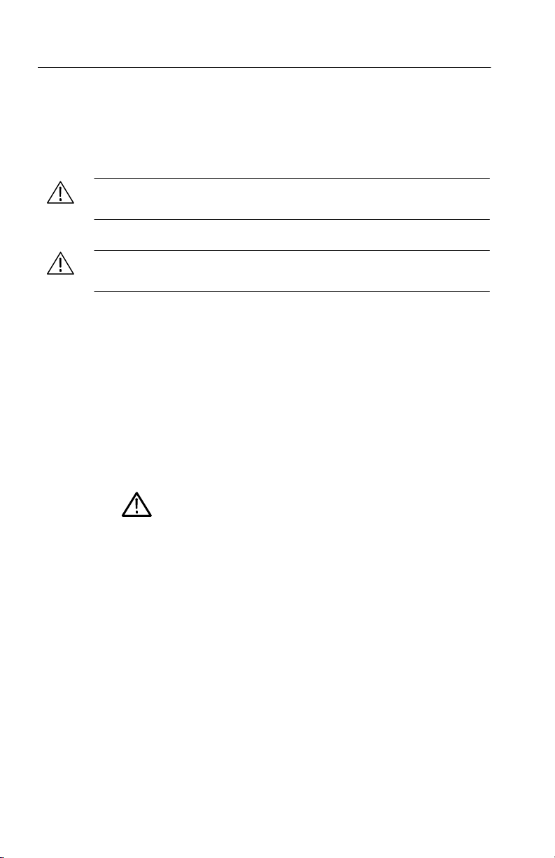
Description
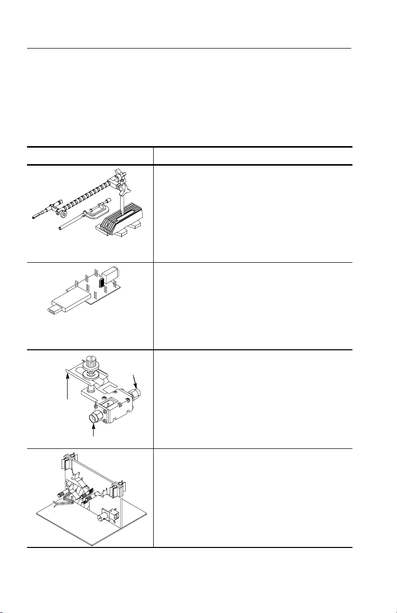
Probe head assembly. The probe head is
designed for ease of use and high performance.
The small size makes it easy to handle in tight
areas.
The probe head features a slot that is designed
for holding accessories in place.
Accessory
slot
TEKPROBE interface. The TEKPROBE
interface provides a communication path between
the probe and the host instrument. Contact pins
provide power, signal, offset, and probe
characteristic data transfer. See page 43 for more
information.
If your host instrument does not support the
TEKPROBE interface, you can use the optional
1103 probe power supply as an effective
interface. Contact your local Tektronix representative for more information.
P6241 4.0 GHz 10X Active Probe Instruction Manual
3
Features and Accessories
Table 1: P6241 features and standard accessories (Cont.)
Feature/Accessory Description
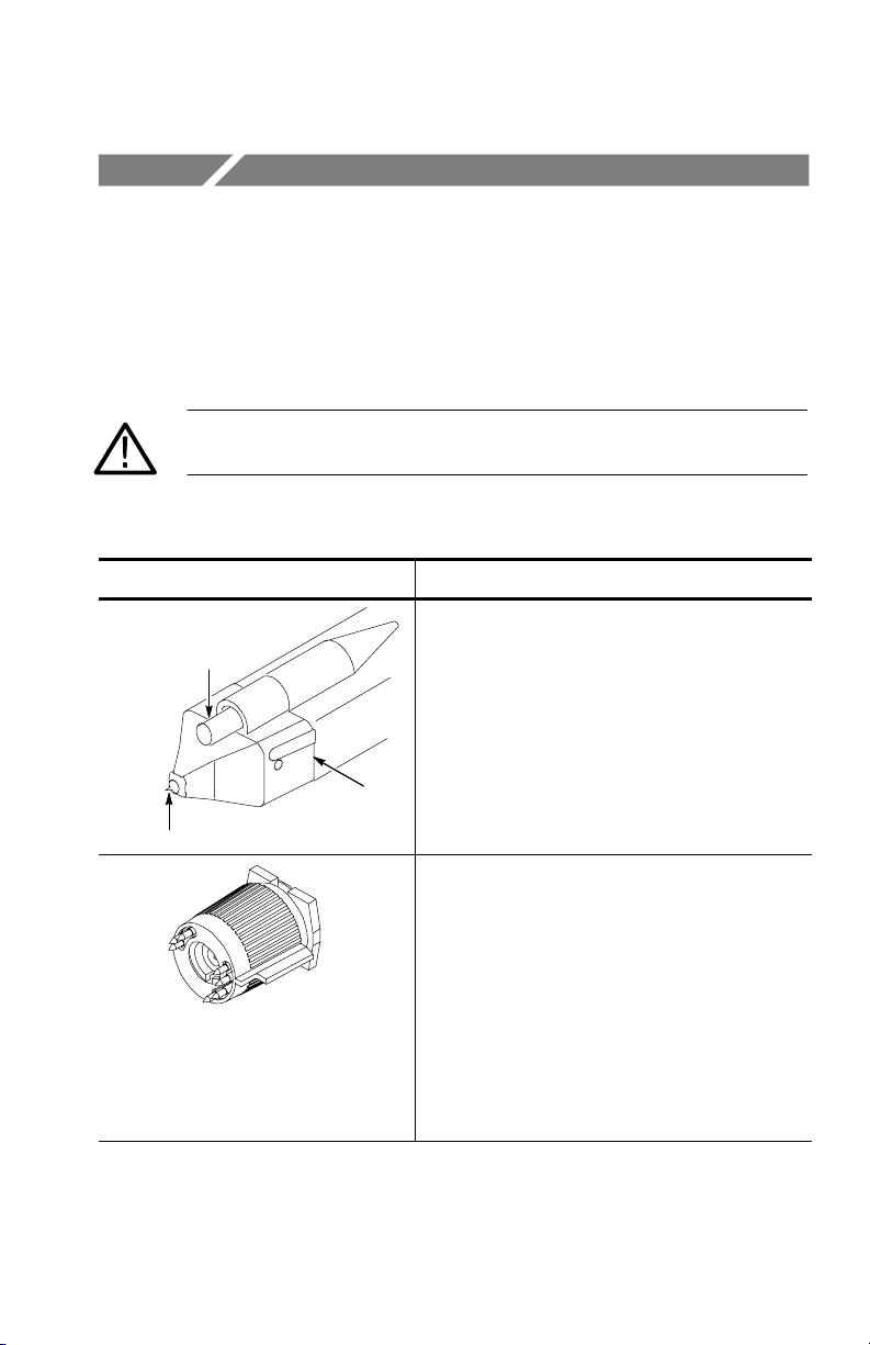
Short ground pogo pin.
This pogo ground pin has a flexible reach of .070
to 1.00 inches, and a .083 inch nominal center
Pogo pin
space. The pin retracts when pressure is applied.
When a short ground is required for probing,
insert the pogo pin into the ground socket of the
probe or adapter.
When selecting the grounding connection,
maintain as short a ground path as possible.
Refer to page 27 for more grounding information.
Tektronix part number: 016-1917-XX (1 set)
Z lead.
Use the Z lead to ground the probe when the
distance between the DUT test point and ground
is greater or less than about 0.100 in. (the fixed
distance between the probe tip and probe
ground).
.180 in
4
You can rotate the Z-lead in the probe ground
socket to accomodate distances of approximately
0.020 to 0.180 in.
.020 in
Tektronix part number: 196-3491-XX (1 set)
P6241 4.0 GHz 10X Active Probe Instruction Manual
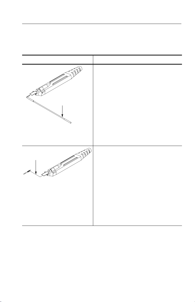
Table 1: P6241 features and standard accessories (Cont.)
Feature/Accessory Description
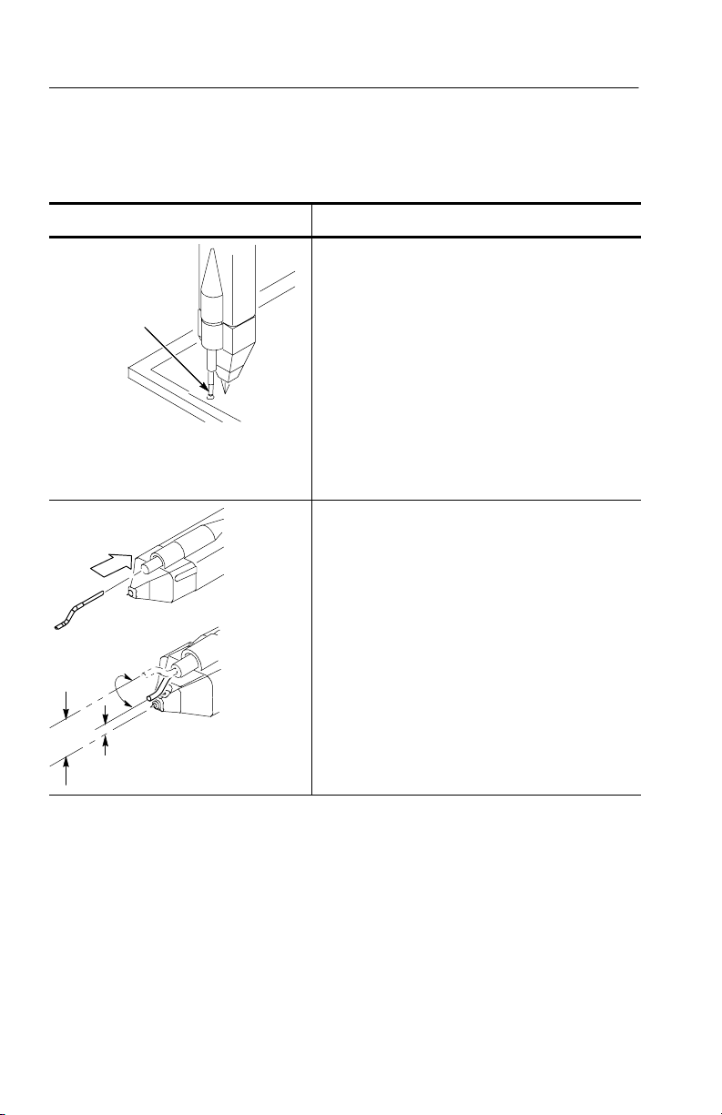
Three-inch ground lead. Use the three-inch
ground lead for general probing. The socketed
end of the lead may be connected to any of the
probe tips and adapters or fitted onto 0.025 inch
square pins.
Three--inch
ground lead
To attach the ground lead, press and rotate the
lead pin connector into the ground socket on the
probe head. The lead may be removed by pulling
the pin out by hand.
When selecting the grounding connection,
maintain as short a ground path as possible.
Refer to page 27 for more information.
Tektronix part number: 196-3437-10 (1 set)
Customizable
ground lead
Customizable ground lead. This ground lead
wire can be bent or cut shorter.
NOTE: To ease insertion into the ground socket
of the probe, cut the tip of this ground lead wire at
a 30 to 60 degree angle.
Features and Accessories
To maintain signal fidelity while probing, use as
short a ground path as possible. Refer to page 27
for more grounding information.
This accessory is not intended for use with the
Square-pin adapter (Tektronix part number
016-1910-XX).
Tektronix part number: 196--3482--XX (1 set)
P6241 4.0 GHz 10X Active Probe Instruction Manual
5
Features and Accessories
Table 1: P6241 features and standard accessories (Cont.)
Feature/Accessory Description
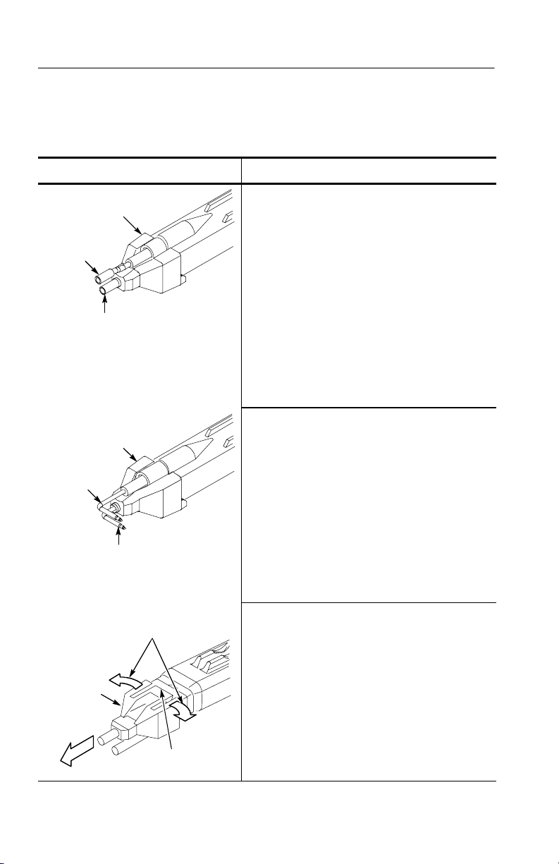
Square-pin adapter
Square-pin
ground socket
extension
Square-pin or
accessory socket
L-adapter
Ground socket
extension
Signal pin
Gently rock the adapter side-to-side
as you pull the adapter straight off
Bottom
view
Do not bend tab!
Square-pin adapter.
This adapter has a socket for holding a square
pin, or an adapter such as the SureToe,
SMT KlipChip, and Y-lead adapters. A square-pin
ground socket extension that you insert into the
ground socket of the probe is included. These
sockets can accept 0.100 inch or 0.080 inch
centered square pins.
To attach the square-pin adapter, hold it between
your thumb and forefinger, and gently slip it over
the probe head until the accessory slot on the
probe head holds the adapter in place.
Tektronix part number: 016-1910-XX (1 set)
L-adapter.
This adapter enables you to probe and ground at
right angles to the device under test (DUT), while
holding the probe parallel to the DUT. A ground
socket extension that you insert into the ground
socket of the probe is included.
To attach the L-adapter, hold it between your
thumb and forefinger and gently slip it over the
probe head until the accessory slot on the probe
head holds the adapter in place.
Tektronix part number: 016-1913-XX (1 set)
Removing the Square-pin and L-Adapters.
Caution! The Square-pin and L-adapters have a
tab on the bottom side of the probe. (See
illustration). When you remove these adapters, do
not bend the tab, otherwise you will break the tab.
To safely disengage the adapter from the probe
tip, grasp the sides of the adapter (not the tab),
and gently rock the adapter side-to-side as you
pull the adapter straight off of the probe.
6
P6241 4.0 GHz 10X Active Probe Instruction Manual
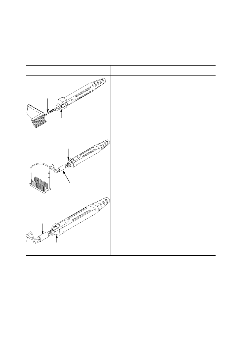
Table 1: P6241 features and standard accessories (Cont.)
Feature/Accessory Description
SureToe adapter (4 ea). The SureToe adapter is
SureToe
adapter
a pointed probe tip useful for probing in IC legs.
Mount the SureToe adapter in the signal pin
socket of the Square-pin adapter. Attach the
SureToe adapter the same way as you attach the
push-in probe tips. This adapter can be used with
Square-pin
adapter
any of the socketed accessory leads.
Tektronix part number: ST501 (package of 12)
Square-pin adapter
Y-lead adapter. Use the Y-lead adapter to extend
the physical reach of the probe and ground when
necessary. The Y-lead adapter accepts any of the
probe tips or adapters, and can be pushed
directly onto the Square-pin adapter.
When selecting the grounding connection,
Y-lead adapter
maintain as short a ground path as possible.
Refer to page 27 for more grounding information.
To attach the Y-lead adapter, gently press the
lead pins into the signal and ground sockets of
Y-lead
adapter
the Square-pin adapter.
Using the black lead for ground is recommended.
Features and Accessories
Square-pin
adapter
Tektronix part number 196-3434-XX (2 each)
P6241 4.0 GHz 10X Active Probe Instruction Manual
7
Features and Accessories
r
Table 1: P6241 features and standard accessories (Cont.)
Feature/Accessory Description
Square-pin adapte
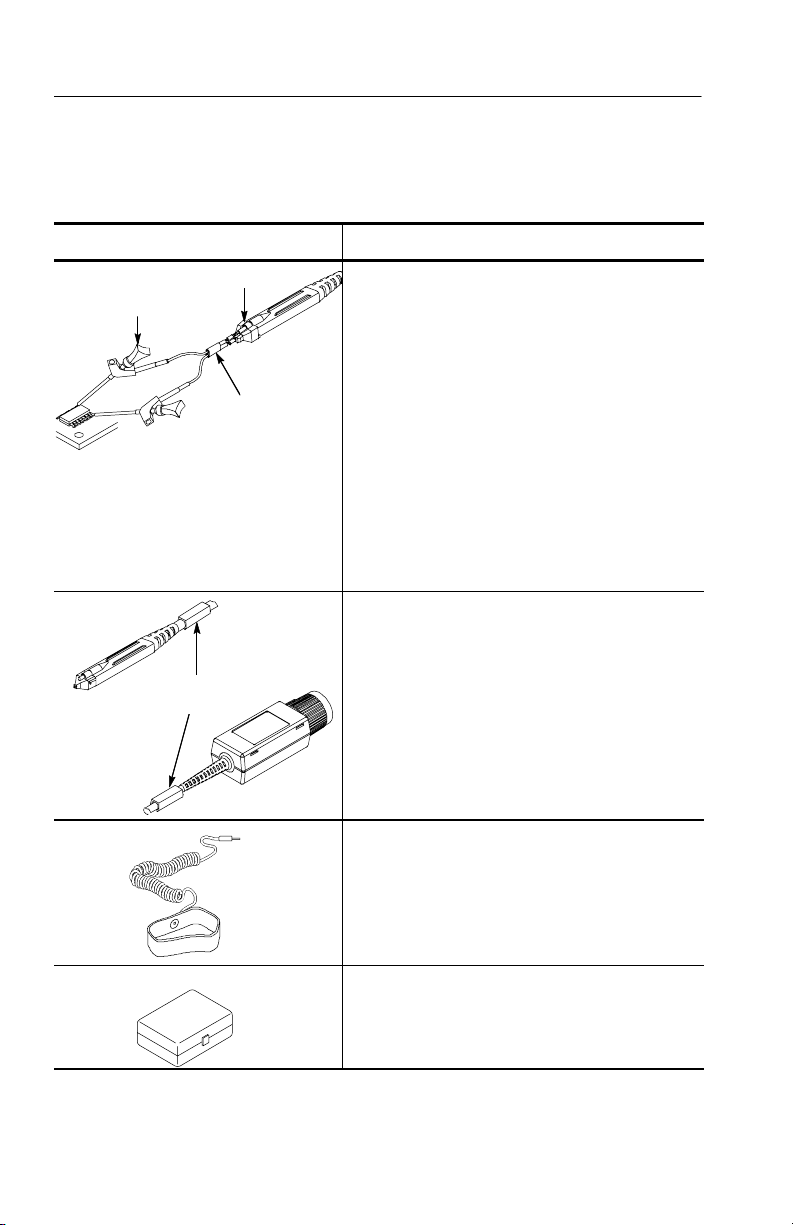
SMT KlipChip
SMT KlipChip. Use the clips of the SMT KlipChip
to access fragile, dense circuitry.
To use SMT KlipChips with the probe, connect
the Square-pin adapter to the probe head. Plug
the KlipChips into the Y-lead adapter, and then
Y-lead adapter
connect the Y-lead adapter to the Square -pin
adapter.
The SMT KlipChip body turns freely, allowing
better probe orientation. To reduce stress and
provide a low profile on components being tested,
the flexible sleeve of the SMT KlipChip bends up
to a 35 degree angle.
Tektronix part number: 206-0364-XX (2 each)
Color marker bands. Attach matching pairs of
the color marker bands onto the cable at the head
and compensation box of each probe. The marker
Color marker
bands
bands enable quick identification of which probe
is connected to which instrument channel.
Tektronix part number: 016-1315-XX ( 1 set)
Antistatic wrist strap. When using the probe,
always work at an antistatic work station, and
wear the antistatic wrist strap.
Tektronix part number: 006-3415-XX ( 1 each)
Plastic accessory box. Use the plastic box to
store the probe accessories when not in use.
Tektronix part number: 006-7164-XX
8
P6241 4.0 GHz 10X Active Probe Instruction Manual
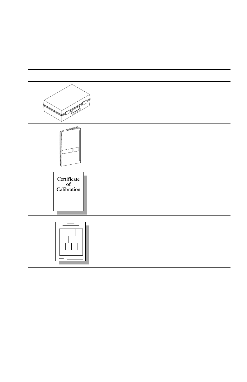
Table 1: P6241 features and standard accessories (Cont.)
Feature/Accessory Description
Instrument case. The instrument case protects
the probe from harsh environments.
Tektronix part number: 016-1879-XX
Instruction Manual. Provides specifications and
instructions for operating the probe, and a list of
accessories and adapters.
Tektronix part number: 071-1188-XX
Calibration certificate. A certificate of traceable
calibration is provided with every instrument
shipped.
Features and Accessories
Accessory reorder sheet. The accessory
reorder sheet provides photos and part numbers
for identifying standard and optional accessories
that are compatible with your probe.
Tektronix part number 001-1349-XX
P6241 4.0 GHz 10X Active Probe Instruction Manual
9
Features and Accessories
Table 2 lists the optional accessories that you can order for your
probe.
Table 2: Optional accessories
Feature/Accessory
Probe holder
50 Ω termination
SMA
connector
Description
PPM100 Probe Positioner. The PPM100 is a general
purpose bench top probe holder with flexible arm,
designed for hands-free probing and fine positioning
adjustments. The heavy duty base can be replaced
with the clamp for securing the probe arm in a variety
of situations. Use flexible retention rings to attach the
probe to the probe holder.
Tektronix part number: PPM100
IEEE1394 Adapter. The IEEE1394 Adapter allows you
to probe signals on the bus, external to system
enclosures, without disturbing system operation. The
adapter maintains a balanced 50 Ω signal path and
can be used in both single-ended and differential
modes.
Tektronix part number: 679-5027-XX
Probe Calibration Fixture. Use this calibration fixture
to connect the probe to SMA cables. The fixture
includes a removable 50 Ω termination. The calibration
fixture is required when performance verification is
done for the probe.
Tektronix part number: 067-1456-XX
Deskew Fixture. This fixture provides a edge source
to time align (deskew) and to optimize host instrument
gain and offset accuracy at the probe tip. The probes
are held in place allowing hands-free operation without
requiring a probe arm.
10
Tektronix part number: 067-0484-XX
P6241 4.0 GHz 10X Active Probe Instruction Manual
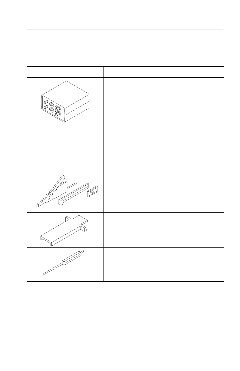
Table 2: Optional accessories (Cont.)
Feature/Accessory Description
1103 Power supply. Order the 1103 power supply for
performance verification procedures. Power cord
options are available for the following countries or
regions.
Standard. North America and Japan
Option A1. European
Option A2. UK
Option A3. Australia
Option A5. Switzerland
Tektronix part number: 1103
Micro KlipChip adapters. Use the adapters to probe
the leads on integrated circuits that are surfacemounted.
Features and Accessories
Tektronix part number: SMK4 (2 sets of 2)
Release tool. Use for opening the compensation box
to access adjustments.
Tektronix part number: 003-1383-XX
Adjustment tool. Use for making internal adjustments
to the probe.
Tektronix part number: 003-1433-XX
P6241 4.0 GHz 10X Active Probe Instruction Manual
11

Features and Accessories
12
P6241 4.0 GHz 10X Active Probe Instruction Manual
Configuration
The P6241 provides the host instrument with the probe model
number, serial number, and attenuation factor. When connected to a
host instrument with a TEKPROBE interface, display readouts are
corrected for the probe attenuation factor, the instrument input is set
to 50 Ω, and the coupling is set to DC.
CAUTION. Do not attempt to install the P6241 on a nonTEKPROBE
connector. Damage to the probe and connector may result.
If your host instrument does not support the TEKPROBE interface,
use the optional Tektronix 1103 Probe Power Supply. If the P6241 is
used with the Tektronix 1103 Probe Power Supply, be sure to have a
50 Ω termination at the host instrument. Also, set the host instrument
channel coupling to DC.
The probe offset is controlled by the host instrument. If the host
instrument used does not support the TEKPROBE interface, use the
offset controls on the optional Tektronix 1103 Probe Power Supply.
Probe Offset
Use the host instrument or the 1103 power supply to adjust the probe
offset permitting operation within the linear range of the probe.
Using the offset to cancel DC signal components enables optimal
probe performance. See Figure 1 on page 15 for more information.
NOTE. See your host instrument manual for specific instructions on
its operation and offset control.
P6241 4.0 GHz 10X Active Probe Instruction Manual
13
 Loading...