

Page 1

Instructions
P6150
For 50 Ohm Oscilloscopes
070-7173-01
Warning
The servicing instructions are for use by qualified
personnel only. To avoid personal injury, do not
perform any servicing unless you are qualified to
do so. Refer to all safety summaries prior to
performing service.
Page 2

Copyright T ektronix, Inc. All rights reserved.
T ektronix products are covered by U.S. and foreign patents, issued and pending. Information in this publication supercedes
that in all previously published material. Specifications and price change privileges reserved.
Printed in the U.S.A.
T ektronix, Inc., P.O. Box 1000, Wilsonville, OR 97070–1000
TEKTRONIX and TEK are registered trademarks of T ektronix, Inc.
Page 3

WARRANTY
T ektronix warrants that the products that it manufactures and sells will be free from defects in materials and workmanship
for a period of one (1) year from the date of purchase from an authorized T ektronix distributor. If any such product proves
defective during this warranty period, T ektronix, at its option, either will repair the defective product without charge for
parts and labor, or will provide a replacement in exchange for the defective product. Batteries are excluded from this
warranty .
In order to obtain service under this warranty, Customer must notify Tektronix of the defect before the expiration of the
warranty period and make suitable arrangements for the performance of service. Customer shall be responsible for
packaging and shipping the defective product to the service center designated by T ektronix, shipping charges prepaid, and
with a copy of customer proof of purchase. T ektronix shall pay for the return of the product to Customer if the shipment is
to a location within the country in which the T ektronix service center is located. Customer shall be responsible for paying
all shipping charges, duties, taxes, and any other charges for products returned to any other locations.
This warranty shall not apply to any defect, failure or damage caused by improper use or improper or inadequate
maintenance and care. T ektronix shall not be obligated to furnish service under this warranty a) to repair damage resulting
from attempts by personnel other than T ektronix representatives to install, repair or service the product; b) to repair
damage resulting from improper use or connection to incompatible equipment; c) to repair any damage or malfunction
caused by the use of non-T ektronix supplies; or d) to service a product that has been modified or integrated with other
products when the effect of such modification or integration increases the time or difficulty of servicing the product.
THIS WARRANTY IS GIVEN BY TEKTRONIX WITH RESPECT TO THE LISTED PRODUCTS IN LIEU OF
ANY OTHER WARRANTIES, EXPRESS OR IMPLIED. TEKTRONIX AND ITS VENDORS DISCLAIM ANY
IMPLIED WARRANTIES OF MERCHANTABILITY OR FITNESS FOR A PARTICULAR PURPOSE.
TEKTRONIX’ RESPONSIBILITY TO REPAIR OR REPLACE DEFECTIVE PRODUCTS IS THE SOLE AND
EXCLUSIVE REMEDY PROVIDED TO THE CUST OMER FOR BREACH OF THIS WARRANTY. TEKTRONIX
AND ITS VENDORS WILL NOT BE LIABLE FOR ANY INDIRECT , SPECIAL, INCIDENTAL, OR
CONSEQUENTIAL DAMAGES IRRESPECTIVE OF WHETHER TEKTRONIX OR THE VENDOR HAS
ADVANCE NOTICE OF THE POSSIBILITY OF SUCH DAMAGES.
Page 4

Contacting Tektronix
Product
Support
Service
Support
For other
information
T o write us T ektronix, Inc.
For application-oriented questions about a T ektronix measurement product, call toll
free in North America:
1-800-TEK-WIDE (1-800-835-9433 ext. 2440)
6:00 a.m. – 5:00 p.m. Pacific time
Or contact us by e-mail:
tm_app_supp@tek.com
For product support outside of North America, contact your local T ektronix distributor
or sales office.
Contact your local T ektronix distributor or sales office. Or visit our web site for a
listing of worldwide service locations.
http://www .tek.com
In North America:
1-800-TEK-WIDE (1-800-835-9433)
An operator will direct your call.
P.O. Box 1000
Wilsonville, OR 97070-1000
Page 5

General Safety Summary
Review the following safety precautions to avoid injury and prevent damage to
this product or any products connected to it. To avoid potential hazards, use this
product only as specified.
To Avoid Fire or
Personal Injury
Symbols and Terms
Connect and Disconnect Properly . Do not connect or disconnect probes or test
leads while they are connected to a voltage source.
Observe All Terminal Ratings. To avoid fire or shock hazard, observe all ratings
and markings on the product. Consult the product manual for further ratings
information before making connections to the product.
The common terminal is at ground potential. Do not connect the common
terminal to elevated voltages.
Do not apply a potential to any terminal, including the common terminal, that
exceeds the maximum rating of that terminal.
Do Not Operate With Suspected Failures. If you suspect there is damage to this
product, have it inspected by qualified service personnel.
Do Not Operate in Wet/Damp Conditions.
Do Not Operate in an Explosive Atmosphere.
Keep Product Surfaces Clean and Dry .
T erms in this Manual. These terms may appear in this manual:
CAUTION. Caution statements identify conditions or practices that could result in
damage to this product or other property.
P6150 Instructions
i
Page 6

General Safety Summary
ii
P6150 Instructions
Page 7

Operating Basics
The P6150 is a high-frequency low-capacitance passive probe designed to be
used with 11800 Series oscilloscopes. The P6150 comes standard with a one
meter SMA male-to-male cable assembly and 1X and 10X attenuators. The
probe head has a female SMA connector that screws into the cable assembly.
The low capacitance and constant input resistance of the P6150 make it possible
to probe high-frequency circuits without disturbing the circuit with a large
capacitive load.
This manual describes the operation of the P6150 probe connected to a Tektronix
11801/11802 sampling oscilloscope with SD-24/SD-26 sampling head. The
P6150 probe may also be used with any 50 W input instrumentation.
CAUTION. Before connecting the probe to the SD-24 sampling head, you should
eliminate potential electrostatic build up from the probe cable. To discharge the
cable with the probe head attached, momentarily connect the probe tip to the
cable or probe ground. A charge stored in the 50 cable (if at high enough
voltage) can damage the SD-24 input.
To maintain consistent signal quality, torque system SMA connectors to
5 inch-pounds.
Do not exceed the input voltage rating of the sampling head (±3 V for SD-24) or
damage to the head can result. The peak input voltage rating is increased by the
attenuation factor of the probe head (for example, 10X times ±3 V is ±30 V).
The RMS input voltage rating is limited by the power handling capacity of the
attenuator resistor. For example, if the 10X attenuator is rated at 1/4 watt, the
RMS input voltage should be limited to less than 12.5 V
The ceramic probe tip resistor network in the 10X probe head is very susceptible
to damage if excessive vertical or angular pressure is applied.
CAUTION. The ceramic resistor network is in danger of breaking if more than five
pounds of vertical (down) pressure or more than three pounds of angular
pressure (pressure that will cause the resistor to attempt to flex), is applied to the
probe tip or ceramic resistor.
Avoid excessive vertical or angular pressure, dropping or hitting the probe, or
allowing the probe to swing against a hard surface. Always place the probe-tip
protector (supplied) on the tip when the probe is not in use.
RMS
.
P6150 Instructions
1
Page 8

Operating Basics
System Response
Figure 1 shows typical system responses with various cable and attenuator
combinations. The system consists of a Tektronix 11801 sampling oscilloscope
and SD-24 TDR sampling head driven by the internal calibrator pulser.
1. Response of 22 cm cable (174-1120-00); 50 mV/div, t
2. Response of 1 m cable (174-1341-00); 50 mV/div, t
= 30 ps.
r
= 43 ps.
r
3. Response of 1 m cable with the 10X probe head in the probe tip adapter.
(013-0251-00); 5 mV/div, t
= 39 ps.
r
4. Response of the 10X probe head with 22 cm cable (174-1120-00); 5 mV/div,
= 32 ps.
t
r
1
2
3
4
Figure 1: Typical system response
2
P6150 Instructions
Page 9
Probe Tip Grounding
Operating Basics
The quality of ground at the probe tip affects performance. For minimum rise
time and aberrations, keep the ground lead short and the ground contact as close
as possible to the point being probed.
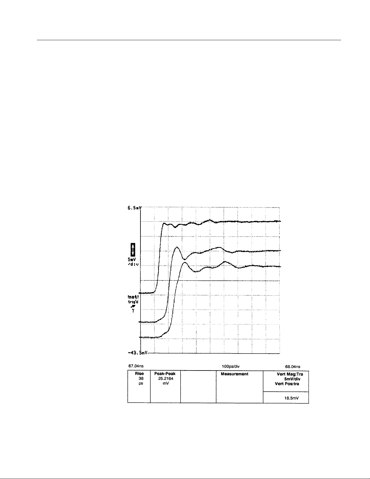
Figure 3 shows typical system responses with different probe tip grounding
methods. Measurements were taken with the 10X attenuator head while probing
the microstrip line on the probe tip adapter (013-0251-00).
1. Response with 013-0251-00 probe tip adapter, t
= 38 ps.
r
2. Response with ground clip cut to the probe tip length. (package of 20
included with accessories: 020-1708-00; t
= 52 ps.
r
3. Response with full length ground clip. (package of 20 included with
accessories: 020-1708-00); t
= 81 ps.
r
1
2
3
P6150 Instructions
Figure 2: Probe tip grounding
3
Page 10

Operating Basics
Input Impedance
Typical input impedance vs frequency of the 10X attenuator.
Ohms
1k
Ohms
)
mag (Zi
n
Degrees
in
Frequency
)
100
10
10meg 100meg 1g 10g
phase (Z
Figure 3: Input impedance
Degrees
10
0
–10
–20
–30
–40
–50
–60
Attenuator Color Coding
Table 1 identifies P6150 probe tip attenuation factors by color color coding.
4
T able 1: Probe tip attenuation factors
Color Attenuation Factor
Black 1X
Blue 10X
P6150 Instructions
Page 11

Maintenance
Operating Basics
Use the following procedures to clean and maintain the P6150 probe.
Cleaning
Probe Module
Replacement
Remove accumulated dust from the outside of the probe with a soft cloth or a
small brush. Remove any remaining dirt with a soft cloth dampened in a mild
detergent and water solution. Do not use abrasive cleaners.
CAUTION. Do not use cleaning agents that may damage the plastic components
of the probe. In particular, avoid solvents such as benzene, toluene, xylene,
acetone, or MEK.
The P6150 probe heads are sealed and contain no user-serviceable parts.
P6150 Instructions
5
Page 12

Specifications
The following specifications apply when the instrument warms up for a period of
at least 20 minutes in an environment that does not exceed the limits described in
Table 3 below.
T able 2: Electrical characteristics
Characteristic 1X 10X
Attenuation Tolerance
Input Resistance
Input Capacitance N/A ≤0.15 pF
1,2
1
±2% ±2%
50 +2% –1% 500 ±1.25%
Maximum Continuous Nondestructive
Input Voltage
Bandwidth at Probe Tip
Rise Time at Probe Tip
Signal Delay 4.40 ±0.1 ns 4.40 ±0.1 ns
1
System characteristic.
2
Oscilloscope input must be 50 ±1%.
3
In-system measurement.
3
3
Oscilloscope maximum
input voltage
≥3.0 GHz 9 GHz
≤170 ps ≤38.8 ps
12.5 V
RMS
T able 3: Environmental characteristics
Characteristic Description
Temperature Range
Operating –15 C to +55 C (+5 F to +131 F)
Nonoperating –62 C to +85 C (–80 F to +185 F)
Humidity
1
1
Reference to MIL-E-1600F, paragraph 4.5.9 through 4.5.9.5.1, class 4.
Five cycles (120 hr) at 95% to 97%
relative humidity 30 C to 60 C
T able 4: Physical characteristics
Characteristic Description
Length 1 m (3.3 ft.)
Shipping Weight 595 g (1.31 lbs. )
6
P6150 Instructions
Page 13

Replaceable Parts
Figure 4: P6150 probe with accessories
1
2
3
7
4
5 6
8
P6150 Instructions
7
Page 14

Replaceable Parts
Replaceable parts: P6150 probe and accessories
Fig. &
index
number
4 –1 174–1341–00 1 CABLE ASSY,RF:50 OHM COAX,39.37 L,8–N 60381 500–1117–00
–2 206–0398–00 1 PROBE HEAD ASSY:1X P6150 80009 206–0398–00
–3 206–0399–00 8905 2 PROBE HEAD ASSY:10X,RES NTWK,450 OHM 80009 206–0399–00
–4 –––––––––– 20 .CONTACT,ELEC:GND,CLIP,PH,BRZ
–5 –––––––––– 10 .CONTACT,ELEC:GND,LEAD,0.025 WIRE NICKEL
–6 –––––––––– 3 .CONTACT,ELEC:0.025 NICKEL ALLOY 52 WIRE
–7 013–0251–00 1 ADAPTER,P TIP:SMA TO P6150 80009 013–0251–00
–8 131–4209–00 1 CONNECTOR,PROBE:PROBE TO CKT BD ADAPTER 80009 131–4209–00
Tektronix
part number
206–0399–02 8906 2 PROBE HEAD ASSY:10X RES NTWK,450 OHM 80009 206–0399–02
020–1708–00 1 ACCESSORY PKG:STANDARD ACCESS T O P6150 80009 020–1708–00
070–7173–00 1 SHEET,TECHNICAL:P6150 TK2548 PER TEK P/N
174–1341–00 1 CABLE ASSY,RF:50 OHM COAX,39.37 L,8–N 60381 500–1117–00
174–1120–00 1 CA ASSY ,RF:COAXIAL,RFD,50 OHM,8.5 L TK2469 174–1 120–00
206–0398–00 1 PROBE HEAD ASSY:1X 80009 206–0398–00
206–0398–01 8904 1 PROBE HEAD ASSY:PKG OF 5,1X 80009 206–0398–01
206–0399–00 8904 1 PROBE HEAD ASSY:10X,RES NTWK,450 OHM 80009 206–0399–00
206–0399–01 8904 1 PROBE HEAD ASSY:PKG OF 3,10X 80009 206–0399–01
206–0399–02 8905 1 PROBE HEAD ASSY:10X 80009 206–0399–02
Serial no.
effective
Serial no.
discont’d
Qty Name & description Mfr. code Mfr. part number
P6150
STANDARD ACCESSORIES
.(ORDER 020–1708–00)
.(ORDER 020–1708–00)
.(ORDER 020–1708–00)
OPTIONAL ACCESSORIES
Manufacturers cross index
Mfr.
code
60381 PRECISION INTERCONNECT CORP. 16640 SW 72ND AVE PORTLAND, OR 97224
80009 TEKTRONIX INC 14150 SW KARL BRAUN DR
TK2469 UNITREK CORPORATION 3000 LEWIS & CLARK HWY
Manufacturer Address City , state, zip code
BEAVERT ON, OR 97077–0001
PO BOX 500
VANCOUVER, W A 98661
SUITE 2
8
P6150 Instructions
 Loading...