

Page 1

Instruction Manual
P6131
10X Passive Probe
for 2400 Series Oscilloscopes
070-5514-03
Warning
The servicing instructions are for use by qualified
personnel only. To avoid personal injury, do not
perform any servicing unless you are qualified to
do so. Refer to all safety summaries prior to
performing service.
www.tektronix.com
*P070551403*
070551403
Page 2

Copyright © T ektronix, Inc. All rights reserved.
T ektronix products are covered by U.S. and foreign patents, issued and pending. Information in this publication supercedes
that in all previously published material. Specifications and price change privileges reserved.
T ektronix, Inc., P.O. Box 500, Beaverton, OR 97077-1000
TEKTRONIX and TEK are registered trademarks of T ektronix, Inc.
Page 3

WARRANTY
T ektronix warrants that the products that it manufactures and sells will be free from defects in materials and workmanship
for a period of one (1) year from the date of purchase from an authorized T ektronix distributor. If any such product proves
defective during this warranty period, T ektronix, at its option, either will repair the defective product without charge for
parts and labor, or will provide a replacement in exchange for the defective product. Batteries are excluded from this
warranty .
In order to obtain service under this warranty, Customer must notify Tektronix of the defect before the expiration of the
warranty period and make suitable arrangements for the performance of service. Customer shall be responsible for
packaging and shipping the defective product to the service center designated by T ektronix, shipping charges prepaid, and
with a copy of customer proof of purchase. T ektronix shall pay for the return of the product to Customer if the shipment is
to a location within the country in which the T ektronix service center is located. Customer shall be responsible for paying
all shipping charges, duties, taxes, and any other charges for products returned to any other locations.
This warranty shall not apply to any defect, failure or damage caused by improper use or improper or inadequate
maintenance and care. T ektronix shall not be obligated to furnish service under this warranty a) to repair damage resulting
from attempts by personnel other than T ektronix representatives to install, repair or service the product; b) to repair
damage resulting from improper use or connection to incompatible equipment; c) to repair any damage or malfunction
caused by the use of non-T ektronix supplies; or d) to service a product that has been modified or integrated with other
products when the effect of such modification or integration increases the time or difficulty of servicing the product.
THIS WARRANTY IS GIVEN BY TEKTRONIX WITH RESPECT TO THE LISTED PRODUCTS IN LIEU OF
ANY OTHER WARRANTIES, EXPRESS OR IMPLIED. TEKTRONIX AND ITS VENDORS DISCLAIM ANY
IMPLIED WARRANTIES OF MERCHANTABILITY OR FITNESS FOR A PARTICULAR PURPOSE.
TEKTRONIX’ RESPONSIBILITY TO REPAIR OR REPLACE DEFECTIVE PRODUCTS IS THE SOLE AND
EXCLUSIVE REMEDY PROVIDED TO THE CUST OMER FOR BREACH OF THIS WARRANTY. TEKTRONIX
AND ITS VENDORS WILL NOT BE LIABLE FOR ANY INDIRECT , SPECIAL, INCIDENTAL, OR
CONSEQUENTIAL DAMAGES IRRESPECTIVE OF WHETHER TEKTRONIX OR THE VENDOR HAS
ADVANCE NOTICE OF THE POSSIBILITY OF SUCH DAMAGES.
Page 4

Contacting Tektronix
Product
support
Service
support
For other
information
To write us
Web site
For questions about using T ektronix measurement products, call
toll free in North America:
1-800-833–9200
6:00 a.m. – 5:00 p.m. Pacific time
Or contact us by e-mail:
tm_app_supp@tek.com
For product support outside of North America, contact your local T ektronix distributor
or sales office.
T ektronix offers extended warranty and calibration programs as options on many
products. Contact your local T ektronix distributor or sales office.
For a listing of worldwide service centers, visit our web site.
In North America:
1-800–833–9200
An operator can direct your call.
T ektronix, Inc.
P.O. Box 500
Beaverton, OR 97077-1000
USA
www .tektronix.com
Page 5

General Safety Summary
Review the following safety precautions to avoid injury and prevent damage to
this product or any products connected to it. To avoid potential hazards, use this
product only as specified.
Only qualified personnel should perform service procedures.
To Avoid Fire or Personal Injury
Symbols and Terms
Connect and Disconnect Properly . Do not connect or disconnect probes or test
leads while they are connected to a voltage source.
Observe All Terminal Ratings. To avoid fire or shock hazard, observe all ratings
and markings on the product. Consult the product manual for further ratings
information before making connections to the product.
The common terminal is at ground potential. Do not connect the common
terminal to elevated voltages.
Do not apply a potential to any terminal, including the common terminal, that
exceeds the maximum rating of that terminal.
Do Not Operate With Suspected Failures. If you suspect there is damage to this
product, have it inspected by qualified service personnel.
Do Not Operate in Wet/Damp Conditions.
Do Not Operate in an Explosive Atmosphere.
Keep Product Surfaces Clean and Dry .
T erms in this Manual. The following terms may appear in this manual:
P6131 Instruction Manual
WARNING. Warning statements identify conditions or practices that could result
in injury or loss of life.
i
Page 6

Service Safety Summary
Only qualified personnel should perform service procedures. Read this Service
Safety Summary and the General Safety Summary before performing any service
procedures.
Do Not Service Alone. Do not perform internal service or adjustments to this
product unless another person capable of rendering first aid and resuscitation is
present.
ii
P6131 Instruction Manual
Page 7
Operating Basics
Lead Inductance
The P6131 probe is a subminiature, 10X, passive probe designed specifically for
use with Tektronix 2400 Series oscilloscopes. It is fully compatible with the
Tektronix family of subminiature probe accessories. The P6131 is available
with 1.3 and 2 meter cable.
WARNING. To avoid electric shock when using the probe, do not touch the
metallic portions of the probe head while connected to a voltage source.
Inductance introduced by long leads can form resonant circuits that ring and
distort the true waveform if driven by signals containing significant frequency
components at or above resonance. To maintain optimum waveform fidelity,
keep the ground lead and signal input connection as short as possible.
Probe Compensation
Due to variations in oscilloscope input characteristics, probe low-frequency
compensation should be checked and or adjusted if you move the probe from one
oscilloscope input to another. Connect the probe tip to a 1 kHz square wave
signal (such as the oscilloscope calibrator output) and use a nonconductive
low-reactance alignment tool to adjust the compensation capacitor.
High-frequency compensation seldom requires adjustment. However, if the probe
has excessive high-frequency aberrations or insufficient bandwidth, you can
adjust the high-frequency compensation through holes in the compensation box
inner metal shield.
For complete low-frequency and high-frequency compensation adjustment
procedures, see page 10.
P6131 Instruction Manual
1
Page 8
Operating Basics
Grounding the Probe
Connect the probe to the instrument and connect the ground lead to ground
before making any measurement. Ensure that no part of the ground lead contacts
voltage in the circuit under test. Except for the probe tip and BNC center
conductor, all accessible metal (including the ground clip) is connected to the
BNC shell.
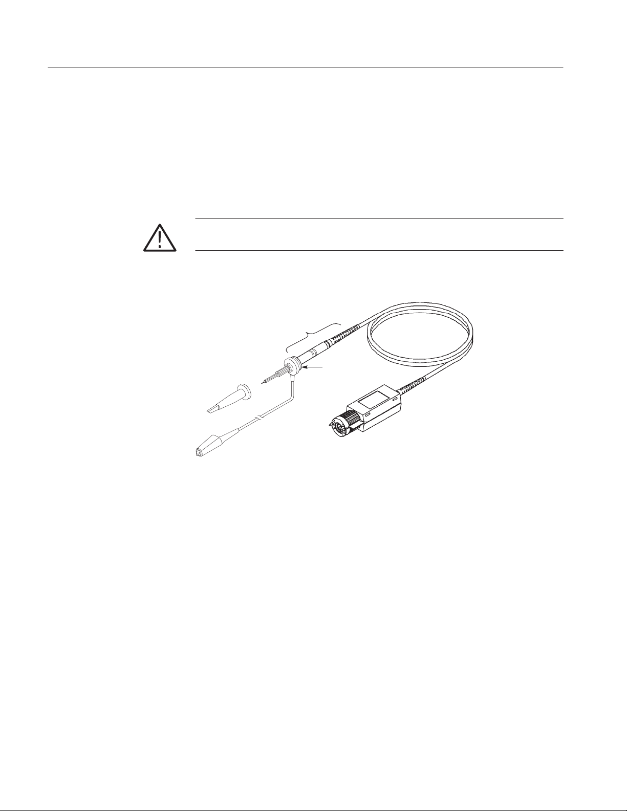
WARNING. To avoid electric shock when using the probe, keep your fingers
behind the finger guard on the probe body. See Figure 1 below.
Hand contact area
Finger guard
Figure 1: Probe finger guard and hand contact area
2
P6131 Instruction Manual
Page 9
Specifications
The characteristics listed in Table 1 apply to P6131 probes installed on Tektronix
2445 and 2465 oscilloscopes or 7A42 plug-ins, unless otherwise noted.
Specifications apply when the instruments warm up for a period of at least
20 minutes in an environment that does not exceed the limits described in
Table 2 on page 5.
T able 1: Electrical characteristics
Characteristic Description
Attenuation
Input resistance
Input capacitance
Compensation range 14 pF to 18 pF
Signal delay
2
2,3
3
1.3 m 10.8 pF
2 m 13.5 pF
1
10X: ±1% at DC
10 MW ±1% at DC
1.3 m 6.3 ns ±100 ps
2 m 9.0 ns ±200 ps
System bandwidth (–3 dB) On a 2465 or 7A42: On a 2445:
1.3 m ≥300 MHz ≥150 MHz
2 m ≥250 MHz ≥150 MHz
Maximum Input Voltage
1
Probe installed on Tektronix 150 MHz (or less) 2400 Series oscilloscope.
2
System characteristic.
3
Also see Figure 3.
4
As defined in EN61010-1. See Certifications and compliances in Table 4
5
RMS=Root Mean Square=rms=The square root of the average of the sum of the
squares of the instantaneous voltage in one cycle = .
300 VDC=300V RMS, 420 V Peak (sinewave)=300 V RMS See Figure 2
4,5
300 V RMS CAT I or 300 V DC CAT I
150 V RMS CAT II or 150 V DC CAT II
100 V RMS CAT III or 100 V DC CAT III
425 V peak, @50% DF, <1 sec PW
750 V peak, @10% DF, <50 ms PW
See Figure 4 for voltage derating curve.
Ǹ
ȍ
(fxi)2ńn
.
P6131 Instruction Manual
3
Page 10

Specifications
@25% Duty Factor
=(1/2 Peak V) RMS
@50% Duty Factor
=(1.414 (Peak V)) RMS
Special case of square wave:
@20% Duty Factor
2
)
=[(V
Example: Maximum Input Voltage
=[(650 V Pk)
(Duty Factor)]
Peak
2
(.20)]
1/2
1/2
= 290 V RMS
0V
0V
0V
Figure 2: Maximum input voltage calculation example
10M
RP and XP ()
1M
100K
10K
1M
100
0.01 0.1 1 10 100 1000
Frequency (MHz)
Figure 3: Typical P6131 Xp and Rp versus frequency
4
P6131 Instruction Manual
Page 11

Voltage
(RMS)
500
100
10
1 10 100
Frequency (MHz)
Figure 4: Typical P6131 voltage derating versus frequency
Specifications
T able 2: Environmental characteristics
Characteristic Description
Temperature range
Operating –15_ C to 65_ C (+5_ F to 149_ F)
Nonoperating –62_ C to 85_ C (–80_ F to 185_ F)
Humidity Five cycles (120 hr) at 95% to 97% relative
humidity, per Tektronix standard 062-2847-00,
Class 3.
Refer to MIL-E016400F, paragraph 4.5.9
through 4.5.9.5.1, class 4.
Altitude < 2000 meters
T able 3: Physical characteristics
Characteristic Description
Net weight
Probe cable length 1.3 meter (4.3 ft)
1
1
Includes accessories
1.3 meter, 108 g (3.8 oz)
2 meter, 129 g (4.8 oz)
2 meter (6.6 ft)
P6131 Instruction Manual
5
Page 12

Specifications
T able 4: Certifications and compliances
EC Declaration of
Conformity
Overvoltage
Category
Pollution Degree 2 Do not operate in environments where conductive pollutants may be
Safety UL31 11-1, First Edition & IEC61010-2-031, First Edition
Compliance was demonstrated to the following specification as listed in
the Official Journal of the European Communities:
Low Voltage Directive 73/23/EEC as amended by 93/68/EEC:
EN 61010-1/A2
EN 61010-2-031:1994
Category: Examples of Products in this Category:
CA T III Distribution-level mains, fixed installation
CA T II Local-level mains, appliances, portable
CA T I Signal levels in special equipment or parts of
present.
CSA C22.2 No. 1010.1-92 & CAN/CSA C22.2 No. 1010.2.031-94
EN61010-1/A2
EN61010-2-031
Pollution Degree 2
Safety requirements for electrical equipment
for measurement, control, and laboratory use
Particular requirements for hand-held probe
assemblies for electrical measurement and
test
equipment
equipment, telecommunications, electronics
6
P6131 Instruction Manual
Page 13

Service Information
WARNING. The following instructions are for use by qualified service personnel
only. To avoid electrical shock, do not disassemble or maintain the probe while it
is connected to a signal source other than those specified in this procedure.
This section contains detailed performance checks, adjustments, and maintenance procedures. These procedures use external traceable test equipment to
directly check warranted characteristics. If you substitute equipment, always
choose instruments that meet or exceed the minimum specified requirements.
Performance V erification Procedure
Use the following procedure to verify that P6131 probe performs as warranted.
For a list of the warranted specifications, see page 3.
Table 5 lists the test equipment needed to perform the performance verification
and adjustment procedures.
T able 5: Performance verification and adjustment test equipment
Description Minimum requirements Example product
Oscilloscope
Calibration generator Pulse Rise Time: ≤1 ns
Leveled sine wave generator Amplitude: adjustable to 1 V
Precision coaxial cable 50 BNC, 36 inch length T ektronix 012-0482-XX
10X attenuator 50 BNC Tektronix 011-0059-XX
Adapter Subminiature probe-tip-to-BNC male T ektronix 013-0195-XX
2
The P6131 probe is designed specifically for use
with Tektronix 2445 and 2465 oscilloscopes and
the 7A42 plug-in.
Amplitude: ≥0.5 V into 50
Rep Rate: 100 kHz
Accuracy: ±0.25%
Direct error readout
into 50
Frequency range:1 MHz to 300 MHz
p-p
Fixed 50 kHz reference
2
Tektronix 2445, 2465, or 7A42 plug-in
Wavetek 9500 High-Performance
Oscilloscope Calibrator
3
P6131 Instruction Manual
7
Page 14

Service Information
T able 5: Performance verification and adjustment test equipment (cont.)
Description Example productMinimum requirements
T ermination 50 BNC Tektronix 011-0049-XX
Low-reactance alignment tool 2 inch shaft, .050 inch bit size Tektronix 003-0675-XX
2
To confirm the full bandwidth specification of the P6131 probe, use the following equipment: a Tektronix 2465 oscilloscope or 7904 oscilloscope with 7B92A time base and 7A42 vertical amplifier and a leveled sine wave generator capable
of 300 MHz output. If you use the probe with a Tektronix 2445 oscilloscope, the bandwidth specification is lower; see
Table 1 on page 3.
3
The maximum sensitivity of the 7A42 plug-in is 20 mV/division. When using the 7A42 to check P6131 probes, double the
amplitude settings in the procedures to follow.
NOTE. To ensure accurate measurements, warm up all test equipment for at least
20 minutes before beginning any performance verification or adjustment
procedure.
Bandwidth Check
To check probe bandwidth do the following:
1. Connect the test setup as shown in Figure 5.
Leveled sine wave
Output
generator
50 Termination
Subminiature
probe-tip-to-BNC
adapter
P6131
probe head
Test oscilloscope
Compensation
box
Figure 5: Bandwidth check setup
2. Set the test oscilloscope controls as follows:
Volts/Division 0.1 V (includes 10X probe attenuation)
Time/Division 1 ms
Input Coupling DC
Bandwidth Full
Vertical input
3. Set the leveled sine wave generator to 50 kHz.
8
P6131 Instruction Manual
Page 15

Service Information
4. Adjust the sine wave generator output amplitude to produce a 6-division
display on the test oscilloscope. Center the waveform on screen.
5. Set the sine wave generator to the high-frequency range and slowly increase
the variable frequency control until the display amplitude decreases to
4.2 divisions (–3 dB) on the oscilloscope.
6. Verify that the sine wave generator frequency readout is greater than or equal
to the values listed in Table 6 for your instrument.
T able 6: Probe bandwidths
2465 Oscilloscope
Probe type
1.3 meter length 300 MHz 150 MHz
2.0 meter length 250 MHz 150 MHz
7A42 Plug-in
2445 Oscilloscope
Attenuation Accuracy
Check
7. If the generator frequency readout is less than the specified value, perform
the low-frequency and high-frequency compensation adjustments beginning
on page 10.
8. Disconnect the test setup.
To check the probe attenuation accuracy do the following:
1. Connect the calibration generator standard amplitude output to the test
oscilloscope vertical input with the precision coax cable.
2. Set the calibration generator controls as follows:
Amplitude Standard
Output 50 mV
Frequency 1 kHz
3. Set the oscilloscope controls as follows:
Volts /Division 10 mV
Time/Division 10 ms
Input Coupling DC
Triggering Obtain a stable display
P6131 Instruction Manual
4. Adjust the calibration generator variable amplitude control to produce a
precise 5-division display on the oscilloscope.
5. Note the oscilloscope deflection error directly from the calibration generator
display for the calculation in step 9 below (Example: +1%).
9
Page 16

Service Information
6. Remove the coax cable from the test setup. Connect the P6131 probe output
to the same vertical input on the oscilloscope.
7. Connect the probe tip through the probe-tip-to-BNC adapter to the standard
amplitude output of the calibration generator. (You must remove the light
gray probe-body shell before inserting the probe tip into the probe-tip-toBNC adapter.)
8. Set the calibration generator output amplitude to 0.5 V and fine tune the
amplitude to produce a precise 5-division display on the oscilloscope.
9. The deflection error indicated by the calibration generator must be within
0.75% of the error noted in step 5 above (probe attenuation accuracy of ±1%
minus the generator uncertainty). Example: if the error noted in step 5 is
+1%, the calibration generator display must now indicate between 0.25%
and 1.75%.
NOTE. You can also check the probe attenuation accuracy with an ohmmeter
having a 10 MW range and ±0.05% or greater accuracy.
Adjustment Procedure
An attenuation accuracy of ±1.0% is assured if the oscilloscope input resistance
is 1 MW ±0.55% (±0.5% tolerance plus 0.05% reading uncertainty) and the
probe-tip-to-output series resistance is indicated to be 9 MW ±0.35% (±1.0%
attenuation accuracy minus ±0.6% input resistance uncertainty minus ±0.05%
reading uncertainty).
10. Disconnect the test setup.
This section contains procedures to adjust the P6131 probe low-frequency and
high-frequency compensations. Always perform the low-frequency compensation
adjustment before proceeding to the high-frequency adjustment.
For a list of test equipment needed to perform the adjustments, see Table 5 on
page 7.
10
P6131 Instruction Manual
Page 17

Service Information
Low-Frequency
Compensation
Adjustment
To adjust the probe low-frequency compensation do the following:
1. Connect the probe output to the test oscilloscope vertical input.
2. Set the oscilloscope controls as follows:
Volts /Division 0.1 V (includes 10X probe attenuation)
Time/Division 1 ms
Input Coupling DC
Bandwidth Full
3. Connect the probe input with hook tip to the oscilloscope calibrator output.
4. Set the oscilloscope triggering for a stable display. The square wave should
be five cycles in length, four divisions in amplitude, and centered on-screen.
5. Using the low-reactance alignment tool, adjust C2010 to optimize the square
wave front corner edge. See Figure 6 for the adjustment location; see
Figure 7 for waveform optimization criteria.
6. Disconnect the test setup.
Metal-shell version
C2010
Plastic-shell version
Figure 6: Low-frequency compensation adjustment locations
P6131 Instruction Manual
11
Page 18

Service Information
Over compensated
Correct
Under compensated
Figure 7: Low-frequency compensation, optimizing the waveform
High-Frequency
Compensation
Adjustment
To adjust the probe high-frequency compensation do the following:
1. Connect the positive-going fast-rise output of the calibration generator to the
test oscilloscope with the precision coax cable and 10X attenuator.
2. Set the oscilloscope controls as follows:
Volts /Division 10 mV (includes 10X probe attenuation)
Time/Division 0.02 ms
Input Coupling DC
Bandwidth Full
3. Set the calibration generator to produce a fast-rise output with a repetition
rate of 10 ms (100 kHz). Adjust the output amplitude to produce a 5 division
display on the oscilloscope.
4. Adjust the oscilloscope triggering for a stable display and center the
waveform on screen.
5. Note the pulse shape and system aberrations for analysis in step 10.
6. Remove the precision coax cable from the test setup.
7. Remove the probe compensation box cover as described below.
Metal shell version: Unscrew the compensation box retainer nut
approximately two complete turns and lift the cover out and up. Press
the cable connector in firmly and retighten the retainer.
12
Plastic shell version: Pry off the darker portion of the plastic shell by
inserting your thumbnails into the seam between the two cover pieces;
then remove the lighter portion from the inner metal shield.
P6131 Instruction Manual
Page 19

Service Information
8. Connect the probe output to the oscilloscope vertical input.
9. Connect the probe tip through the probe-tip-to-BNC adapter and a 50 W
termination to the positive-going fast-rise output of the calibration generator.
(The light gray probe-body shell must be removed before inserting the probe
tip into the probe-tip-to-BNC adapter.)
10. Verify that the high-frequency aberrations do not exceed +6% (5.30
divisions), –6% (4.70 divisions), or 9% (0.45% division) peak to peak, in
addition to the system aberrations noted in step 5 above.
11. If the probe aberrations are within tolerance, proceed to step 14 below. If the
probe aberrations are not within tolerance, continue with step 12 below.
12. Adjust R2021 for the best overall waveform flat response. See Figure 8 for
the location of all adjustments.
13. Adjust R2020, R2010, and C1010 for the best corner response without
ringing. See Figure 9 for the waveform area effected by each adjustment.
NOTE. High-frequency compensation adjustments affect probe bandwidth.
Following the compensation adjustments, verify the probe bandwidth specification using the procedure on page 8. A small overshoot on the leading edge of
the pulse may be tolerated in order to meet the bandwidth specification. The
overshoot should not exceed the typical aberrations described in step 10 above.
14. Reinstall the compensation box cover by performing the procedure described
in step 7 above in reverse order.
15. Disconnect the test setup.
P6131 Instruction Manual
13
Page 20

Service Information
R2010
C1010
R2021
R2020
Metal-shell version
R2010
R2020
R2021
C1010
C2010
Plastic-shell version
Figure 8: High-frequency compensation adjustment locations
≈20 ns
R2021
≈5 ns
R2021
≈3 ns
R2021
C1010
14
Figure 9: High-frequency compensation, optimizing the waveform
P6131 Instruction Manual
Page 21

Maintenance
Service Information
Use the following procedures to clean and maintain the P6131 probe.
Cleaning
Probe Module
Replacement
To remove accumulated dirt from the probe exterior, use a soft cloth dampened
with a nonresidue cleaner, preferably isopropyl alcohol. In particular, avoid
solvents such as benzene, toluene, xylene, or acetone.
Modular construction has been used in the design of the probe to simplify repair.
The probe head, tip assembly, compensation box, and cable are available as
separate units through your local Tektronix field office or representative.
Individual components within the compensation box are not replaceable. See
page 19 for a list of replaceable parts.
The entire probe-head can be replaced by simply pulling the probe-head
assembly away from the cable and pushing a new unit in place. To remove the
compensation box, unscrew the retainer and pull the cable until it separates from
the box.
The probe tip is easily replaced by following the replacement procedure included
with the replacement tips.
P6131 Instruction Manual
15
Page 22

Service Information
16
P6131 Instruction Manual
Page 23

Replaceable Parts
This section contains a list of the replaceable modules for the P6131 probe. Use
this list to identify and order replacement parts.
Parts Ordering Information
Replacement parts are available through your local Tektronix field office or
representative.
Changes to Tektronix products are sometimes made to accommodate improved
components as they become available and to give you the benefit of the latest
improvements. Therefore, when ordering parts, it is important to include the
following information in your order:
H Part number
H Instrument type or model number
H Instrument serial number
H Instrument modification number, if applicable
Module Servicing
If you order a part that has been replaced with a different or improved part, your
local Tektronix field office or representative will contact you concerning any
change in part number.
Change information, if any, is located at the rear of this manual.
Modules can be serviced by selecting one of the following three options. Contact
your local Tektronix service center or representative for repair assistance.
Module Exchange. In some cases you may exchange your module for a reman-
ufactured module. These modules cost significantly less than new modules and
meet the same factory specifications.
Module Repair and Return. You may ship your module to us for repair, after which
we will return it to you.
New Modules. You may purchase replacement modules in the same way as other
replacement parts.
P6131 Instruction Manual
17
Page 24

Replaceable Parts
Using the Replaceable Parts List
This section contains a list of the replaceable mechanical and electrical components for the P6131 probe. Use this list to identify and order replacement parts.
The table below describes the content of each column of the parts list.
Parts list column descriptions
Column Column name Description
1 Figure & index number Items in this section are referenced by figure and index numbers to the exploded view
illustrations that follow.
2 Tektronix part number Use this part number when ordering replacement parts from Tektronix.
3 and 4 Serial number Column three indicates the serial number at which the part was first effective. Column four
indicates the serial number at which the part was discontinued. No entry indicates the part is
good for all serial numbers.
5 Qty This indicates the quantity of parts used.
6 Name & description An item name is separated from the description by a colon (:). Because of space limitations, an
item name may sometimes appear as incomplete. Use the U.S. Federal Catalog handbook
H6-1 for further item name identification.
7 Mfr. code This indicates the code of the actual manufacturer of the part.
8 Mfr. part number This indicates the actual manufacturer’s or vendor’s part number.
Abbreviations
Mfr. Code to Manufacturer
Cross Index
Abbreviations conform to American National Standard ANSI Y1.1–1972.
The table titled Manufacturers Cross Index shows codes, names, and addresses
of manufacturers or vendors of components listed in the parts list.
18
P6131 Instruction Manual
Page 25

Replaceable Parts
1
6
5
16
11
12
13
17
14
10
3
9
8
15
2
4
7
Figure 10: P6131 probe with standard accessories
Replaceable parts: P6131 probe and standard accessories
Fig. &
index
number
10 –1 206–0314–00 1 COMP BOX ASSY:1.3 METER
–2 131–3219–00 1 CONN,RF PLUG:BNC,MALE,STR,THD,10X 24931 28P266–3
–3 200–3018–00 8430 1 COVER,CABLE NIP:COMP BOX 0J260 ORDER BY DESC
–4 200–3017–00 8430 1 COVER,COMP BOX:BOTTOM,ABS SLATE GRAY TK2565 200–3017–00
–5 200–3016–00 8909 1 COVER,COMP BOX:TOP,ABS DOVE GRAY
Tektronix
part number
206–0321–00 1 COMP BOX ASSY:2 METER
200–3016–00 8909 1 COVER,COMP BOX:TOP,ABS DOVE GRAY
Serial no.
effective
Serial no.
discont’d
Qty Name & description Mfr. code Mfr. part number
P6131 PROBE
80009 206–0314–00
(STANDARD ONLY)
80009 206–0321–00
(OPTION 02 ONLY)
TK2565 200–3016–00
(STANDARD ONLY)
TK2565 200–3016–00
(OPTION 02 ONLY)
P6131 Instruction Manual
19
Page 26

Replaceable Parts
Replaceable parts: P6131 probe and standard accessories (cont.)
Fig. &
index
number
10 –6 174–0972–00 8805 1 CABLE ASSY,RF:39 OHM COAX,3.0M
–7 013–0208–02 8820 1 TIP,PROBE:SUBMINIATURE SIZE TK2565 013–0208–02
–8 204–0925–01 1 BODY SHL,PROBE TK2565 204–0925–01
–9 206–0265–10 8628 1 TIP,PROBE:10X,10.3PF,CLEAR/BLUE
–10 196–3305–00 1 LEAD,ELECTRICAL:22 AWG,6.0 L,W/CLIP 060D9 196–3305–00
–11 016–1644–00 1 POUCH,ACCESSORY:6.25 X 9.25 05006 501494
–12 352–0351–00 8924 1 HOLDER,PROBE:BLACK ABS P6000 SERIES 7X318 1127
–13 195–4240–00 1 LEAD,ELECTRICAL:0.025 DIA,COPPER,2.3 L TK2469 195–4240–00
–14 016–0633–00 1 MARKER SET,CA:2 EA VARIOUS COLORS 80009 016–0633–00
–15 343–1003–01 1 COLLAR,GND TK2565 343–1003–01
–16 206–0364–00 9004 1 TIP,PROBE:MICROCKT TEST,0.05 CTR 80009 206–0364–00
–17 003–1433–02 8845 1 SCREWDRIVER:ADJUSTMENT TOOL TK2565 003–1433–02
Tektronix
part number
174–0971–00 8818 1 CABLE ASSY,RF:39 OHM COAX,2.0M
206–0265–12 8628 1 TIP,PROBE:10X,12.5PF,CLEAR YELLOW
196–3113–02 1 LEAD,ELECTRICAL:STRD,22 AWG,6.0 L,8–N TK2469 196–31 13–02
070–5514–03 1 SHEET,TECHNICAL:INSTR,P6131,DP TK2548 070–5514–03
Serial no.
effective
Serial no.
discont’d
Mfr. part numberMfr. codeName & descriptionQty
TK2469 174–0972–00
(STANDARD ONLY)
TK2469 174–0971–00
(OPTION 02 ONLY)
80009 206–0265–10
(STANDARD ONLY)
80009 206–0265–12
(OPTION 02 ONLY)
P6131 PROBE STANDARD ACCESSORIES
20
P6131 Instruction Manual
Page 27

1 2 3 4 5 6
7 8 9 10 11 12
Replaceable Parts
13
14
Figure 11: P6131 probe optional accessories
Replaceable parts: P6131 probe optional accessories
Fig. &
index
number
11 –1 131–5030–00 8926 1 CONNECTOR,PROBE:PKG OF 25,SUBMINIATURE 80009 131–5030–00
–2 013–0195–00 1 ADAPTER,CONN:BNC TO PROBE 24931 28P264–1
–3 013–0202–03 8727 1 ADAPTER,PROBE:SUBMINIATURE/COMPACT TO
–4 015–0325–01 1 ADAPTER,PROBE:PROBE TO CONNECTOR PINS TK2565 015–0325–01
Tektronix
part number
Serial no.
effective
Serial no.
discont’d
Qty Name & description Mfr. code Mfr. part number
P6131 PROBE OPTIONAL ACCESSORIES
TK2565 013–0202–03
MIN
THE SUBMINIATURE–TO–MINIATURE PROBE–TIP
ADAPTER IS REQUIRED TO USE ACCESSORIES IN
INDEX NUMBERS 6 THRU 11
P6131 Instruction Manual
21
Page 28

Replaceable Parts
Replaceable parts: P6131 probe optional accessories (cont.)
Fig. &
index
number
11–5 206–0364–00 8851 1 TIP,PROBE:MICROCKT TEST,0.05 CTR 80009 206–0364–00
–6 013–0084–04 1 ADAPTER,CONN:BNC TO PROBE 80009 013–0084–04
–7 013–0085–00 1 TIP,PROBE:GROUNDING 80009 013–0085–00
–8 352–0670–00 1 HOLDER,PROBE:ATTENUATOR TIPS (3) TK2565 352–0670–00
–9 206–0268–00 1 TIP ASSY,PROBE:1X,SUBMINIATURE 80009 206–0268–00
–10 003–1433–02 8845 1 SCREWDRIVER:ADJUSTMENT TOOL 80009 003–1433–02
–11 016–0633–00 1 MARKER SET,CA:2 EA VARIOUS COLORS 80009 016–0633–00
–12 013–0253–00 9307 1 ADAPTER,CONN:BNC TO PROBE TIP,MALE 24931 28P–302–1
–13 196–3286–00 8921 1 LEAD,ELECTRICAL:26 AWG,10.222 L,0–N
–14 196–3302–00 9004 1 LEAD,ELECTRICAL:23 AWG,6.0 L TK2469 196–3302–00
Tektronix
part number
070–5514–03 1 MANUAL,TECH:INSTR,P6131 TK2548 070–5514–03
Serial no.
effective
Serial no.
discont’d
Mfr. part numberMfr. codeName & descriptionQty
TK2469 196–3286–00
W/ALLIGATOR CLIP
Manufacturers cross index
Mfr.
code
05006 20TH CENTURY BOK 3628 CRENSHAW BOULEVARD
0J260 COMTEK MANUFACTURING OF OREGON P O BOX 4200
24931 BERG ELECTRONICS INC BERG ELECTRONICS RF/COAXIAL DIV
7X318 KASO PLASTICS INC 11013 A NE 39TH VANCOUVER, WA 98662
80009 TEKTRONIX INC 14150 SW KARL BRAUN DR
TK2469 UNITREK CORPORATION 3000 LEWIS & CLARK HWY
TK2548 XEROX CORPORA TION 14181 SW MILLIKAN WA Y BEAVERTON, OR 97005
TK2565 VISION PLASTICS INC 26000 SW PARKWAY CENTER DRIVE WILSONVILLE, OR 97070
Manufacturer Address City , state, zip code
LOS ANGELES, CA 90016
ATTN: CUSTOM DEPARTMENT
BEAVERT ON, OR 970764200
M/S 16–207
FRANKLIN, IN 46131
2100 EARLYWOOD DR
PO BOX 547
BEAVERT ON, OR 97077–0001
PO BOX 500
VANCOUVER, W A 98661
SUITE 2
22
P6131 Instruction Manual
 Loading...