

Page 1

Instruction Manual
P6105A
100 MHz 10X Passive Probe
070-5516-03
Warning
The servicing instructions are for use by qualified
personnel only. To avoid personal injury, do not
perform any servicing unless you are qualified to
do so. Refer to all safety summaries prior to
performing service.
www.tektronix.com
*P070551603*
070551603
Page 2

Copyright © T ektronix, Inc. All rights reserved.
T ektronix products are covered by U.S. and foreign patents, issued and pending. Information in this publication supercedes
that in all previously published material. Specifications and price change privileges reserved.
T ektronix, Inc., P.O. Box 500, Beaverton, OR 97077
TEKTRONIX and TEK are registered trademarks of T ektronix, Inc.
Page 3

WARRANTY
T ektronix warrants that the products that it manufactures and sells will be free from defects in materials and workmanship
for a period of one (1) year from the date of purchase from an authorized T ektronix distributor. If any such product proves
defective during this warranty period, T ektronix, at its option, either will repair the defective product without charge for
parts and labor, or will provide a replacement in exchange for the defective product. Batteries are excluded from this
warranty .
In order to obtain service under this warranty, Customer must notify Tektronix of the defect before the expiration of the
warranty period and make suitable arrangements for the performance of service. Customer shall be responsible for
packaging and shipping the defective product to the service center designated by T ektronix, shipping charges prepaid, and
with a copy of customer proof of purchase. T ektronix shall pay for the return of the product to Customer if the shipment is
to a location within the country in which the T ektronix service center is located. Customer shall be responsible for paying
all shipping charges, duties, taxes, and any other charges for products returned to any other locations.
This warranty shall not apply to any defect, failure or damage caused by improper use or improper or inadequate
maintenance and care. T ektronix shall not be obligated to furnish service under this warranty a) to repair damage resulting
from attempts by personnel other than T ektronix representatives to install, repair or service the product; b) to repair
damage resulting from improper use or connection to incompatible equipment; c) to repair any damage or malfunction
caused by the use of non-T ektronix supplies; or d) to service a product that has been modified or integrated with other
products when the effect of such modification or integration increases the time or difficulty of servicing the product.
THIS WARRANTY IS GIVEN BY TEKTRONIX WITH RESPECT TO THE LISTED PRODUCTS IN LIEU OF
ANY OTHER WARRANTIES, EXPRESS OR IMPLIED. TEKTRONIX AND ITS VENDORS DISCLAIM ANY
IMPLIED WARRANTIES OF MERCHANTABILITY OR FITNESS FOR A PARTICULAR PURPOSE.
TEKTRONIX’ RESPONSIBILITY TO REPAIR OR REPLACE DEFECTIVE PRODUCTS IS THE SOLE AND
EXCLUSIVE REMEDY PROVIDED TO THE CUST OMER FOR BREACH OF THIS WARRANTY. TEKTRONIX
AND ITS VENDORS WILL NOT BE LIABLE FOR ANY INDIRECT , SPECIAL, INCIDENTAL, OR
CONSEQUENTIAL DAMAGES IRRESPECTIVE OF WHETHER TEKTRONIX OR THE VENDOR HAS
ADVANCE NOTICE OF THE POSSIBILITY OF SUCH DAMAGES.
Page 4

Contacting Tektronix
Product
support
Service
support
For other
information
To write us
Web site
For questions about using T ektronix measurement products, call
toll free in North America:
1-800-833–9200
6:00 a.m. – 5:00 p.m. Pacific time
Or contact us by e-mail:
tm_app_supp@tek.com
For product support outside of North America, contact your local T ektronix distributor
or sales office.
T ektronix offers extended warranty and calibration programs as options on many
products. Contact your local T ektronix distributor or sales office.
For a listing of worldwide service centers, visit our web site.
In North America:
1-800–833–9200
An operator can direct your call.
T ektronix, Inc.
P.O. Box 500
Beaverton, OR 97077-1000
USA
www .tektronix.com
Page 5

General Safety Summary
Review the following safety precautions to avoid injury and prevent damage to
this product or any products connected to it. To avoid potential hazards, use this
product only as specified.
Only qualified personnel should perform service procedures.
To Avoid Fire or Personal Injury
Symbols and Terms
Connect and Disconnect Properly . Do not connect or disconnect probes or test
leads while they are connected to a voltage source.
Observe All Terminal Ratings. To avoid fire or shock hazard, observe all ratings
and markings on the product. Consult the product manual for further ratings
information before making connections to the product.
The common terminal is at ground potential. Do not connect the common
terminal to elevated voltages.
Do not apply a potential to any terminal, including the common terminal, that
exceeds the maximum rating of that terminal.
Do Not Operate With Suspected Failures. If you suspect there is damage to this
product, have it inspected by qualified service personnel.
Do Not Operate in Wet/Damp Conditions.
Do Not Operate in an Explosive Atmosphere.
Keep Product Surfaces Clean and Dry .
T erms in this Manual. The following terms may appear in this manual:
P6105A Instruction Manual
WARNING. Warning statements identify conditions or practices that could result
in injury or loss of life.
i
Page 6

Service Safety Summary
Only qualified personnel should perform service procedures. Read this Service
Safety Summary and the General Safety Summary before performing any service
procedures.
Do Not Service Alone. Do not perform internal service or adjustments to this
product unless another person capable of rendering first aid and resuscitation is
present.
ii
P6105A Instruction Manual
Page 7

P6105A Passive Probe
Thank you for choosing a Tektronix passive probe. This manual provides the
information necessary to begin making measurements with your P6105A probe.
Topics are presented in the following order:
H Description—A description of the probe and its options.
H Safety—A review of important safety considerations.
H Installation—Information about attaching the probe to an instrument, and
attaching accessories to the probe.
H Operating Considerations—Information about using the probe.
H Maintenance—Instructions for cleaning the probe and replacing major
assemblies.
H Replaceable Parts—An exploded view of the probe and a list of replaceable
parts.
Description
The P6105A is a miniature, 10X-attenuating passive probe that is compatible
with general purpose oscilloscopes having a 1 MW input impedance.
The P6105A is compatible with Tektronix oscilloscopes that automatically detect
and display the attenuation factor of the attached probe.
The P6105A has a ground-reference push button that momentarily grounds the
probe output. This feature allows you to quickly identify the oscilloscope display
associated with one of several attached probes as well as making ground-referenced measurements easier.
The P6105A is available with the following cable lengths:
Standard 2 meters
Option 01 1 meter
Each probe option is fully compatible with Tektronix accessories for miniature
probes.
P6105A Instruction Manual
1
Page 8

P6105A Passive Probe
Installation
This section describes both attaching the probe to an oscilloscope and using the
standard accessories with the probe.
Attaching the Probe to an
Oscilloscope
Using the Standard
Accessories
The probe uses a BNC connector to attach to an oscilloscope input connector. To
ensure optimum performance from your probe/oscilloscope measurement
system, verify that the probe and oscilloscope are appropriately matched. The
oscilloscope input impedance should be 1 MW. The oscilloscope input capaci-
tance should be between 15 and 35 pF. Refer to “Compensation Range” in
Table 1 on page 8 for more information.
Your P6105A is shipped with the following accessories:
H This instruction manual—Read these instructions to familiarize yourself
with he features, specifications, and operation of the P6105A passive probe.
H Accessory pouch—(not shown) Use the accessory pouch to store the probe
and its accessories when they are not being used.
H Adjustment tool—Use the insulated adjustment tool to adjust the low
frequency trimmer in the probe compensation box.
H IC protector tip—Use the IC protector tip to keep the metal sleeve of the
probe tip from accidentally shorting together the leads of an IC or other
circuit element. The shape of the protector tip helps you place the tip
accurately onto an IC lead.
H Retractable hook tip—Use the retractable hook tip to make hands-free
measurements. The hook tip attaches to components having leads, such as
resistors, capacitors, and discrete semiconductors. You can also grip stripped
wire, jumpers, busses, and test pins with the retractable hook.
For maximum flexibility with the hook tip, use the twelve-inch ground lead.
For precise measurements at high frequency, however, long ground leads
may have too much inductance. In these cases you should use the five-inch
ground lead.
To remove the hook tip, simply pull it off the probe. Reinstall it by pushing
it firmly onto the probe tip.
H Ground cover—Use the protective ground cover to keep the metal sleeve of
the probe tip from accidentally shorting circuit elements to ground. Remove
the ground cover before installing the retractable hook tip.
H Marker rings—Use the marker rings to help you keep track of individual
probes and signal sources when you have a complicated test setup. Use the
marker rings whenever you want to identify a particular probe for any
2
P6105A Instruction Manual
Page 9

P6105A Passive Probe
reason.To make probe identification easy, clip matching colored rings onto
the probe cable and tip as shown.
H Three-inch ground lead—Use the Three-inch ground lead to establish a
ground reference for your measurements. Whenever freedom from aberrations and amplitude accuracy are more important than probe reach and
flexibility, use the shortest ground lead possible.
To attach the ground lead to the probe, insert the spring clip into the
receptacle as shown. If the alligator clip is not attached, screw it onto the
threaded end of the lead.
H Five-inch ground lead—Use the long ground lead when a long reach is
important and high-frequency information is not. Because of the high
inductance associated with long ground leads, you should not use them for
precise measurements above approximately 30 MHz (or for pulses with rise
times less than about 11 ns). Long ground leads are ideal for quick troubleshooting when you are looking for the presence or absence of a signal and
are not concerned with the precision of the measurement.
The five-inch ground lead attaches in the same manner as the three-inch lead.
H Alligator clip—Use the alligator clip with one of the ground leads. Screw
the alligator clip onto the threaded end of a ground lead.
P6105A Instruction Manual
3
Page 10
P6105A Passive Probe
Operating Considerations
This information in this section will help you make the most effective use of
your P6105A probe.
Features and Controls
Readout Pin
Ground-reference
Push Button
Finger guard
H Readout pin—The BNC connector of the probe includes a spring-loaded pin
that connects to a mating contact ring on certain oscilloscopes. These
oscilloscopes recognize the attenuation factor of the probe and automatically
correct the oscilloscope indication of scale factor. You can determine if your
oscilloscope supports this feature by watching the oscilloscope vertical scale
factor readout when attaching the probe. If the displayed scale changes by a
factor of 10—for instance, from 10 mV to 100 mV—your oscilloscope
supports this feature.
H Ground-reference push button—Press the ground-reference push button to
momentarily short the signal output of the probe to ground (the signal under
test is not affected). Using the ground-reference push button allows you to
quickly note or verify the ground reference of a DC measurement. If your
oscilloscope is displaying several traces, pressing the ground-reference push
button also helps you to identify which trace is associated with the probe.
WARNING. To avoid electric shock when using the probe, keep fingers behind the
guard on the probe body.
Ground Lead Inductance
4
In order for an amplitude measurement to be meaningful, you must give the
measurement some point of reference. The ground lead provides access to this
ground reference.
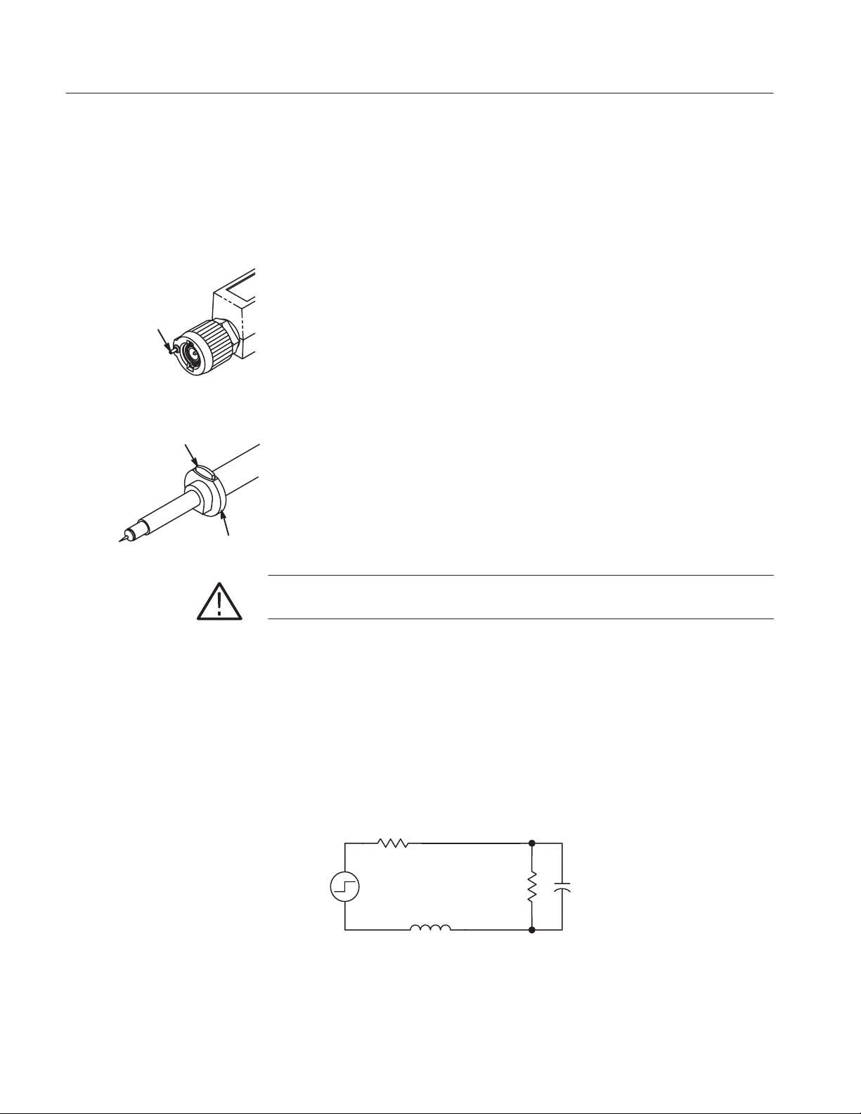
When you subsequently touch your probe tip to a circuit element, you introduce
additional resistance, capacitance, and inductance into the circuit (Figure 1).
Source
Resistance
Probe
V
source
Input
Resistance
Ground Lead Inductance
Probe Input
Capacitance
Figure 1: A Probe Adds Resistance, Capacitance, and Inductance
P6105A Instruction Manual
Page 11

P6105A Passive Probe
A passive probe is capacitive for high-frequency signals. For most circuits, the
high input resistance of a passive probe has a negligible effect on the signal. The
series inductances represented by the probe tip and ground lead, however, can
result in a parasitic resonant circuit that may “ring” within the bandwidth of the
oscilloscope. If the ringing is at a frequency within the oscilloscope bandwidth,
the ringing appears on the oscilloscope display as a distortion of the true
waveform. Figure 2 shows the effect on the same signal through the same probe
with different ground leads.
Long Ground Lead
Low-Frequency Probe
Compensation
Undercompensated
Short Ground Lead
Figure 2: Signal Distortion Introduced by Ground Lead Inductance
Reducing the ground lead inductance will raise the resonant frequency. Ideally,
the inductance is low enough that the resulting frequency is above the frequency
at which you want to take measurements. To maintain the best signal integrity,
use the shortest possible ground lead and signal input path.
Passive probes require compensation to ensure maximum distortion-free output
and to avoid high-frequency amplitude errors.
Because of variations in oscilloscope input characteristics, probe low-frequency
(LF) compensation may need adjustment after moving the probe from one
oscilloscope to another. Verify the compensation before making critical rise time
or amplitude measurements.
If a 1-kHz calibrated square wave displayed at 1 ms/division shows significant
differences between the leading and trailing edges (see figures at left), perform
the following steps to optimize low-frequency compensation.
Overcompensated
Properly Compensated
P6105A Instruction Manual
1. Connect the probe tip to a calibration signal. Most oscilloscopes have a front
panel test point for this purpose; if yours does not, use a signal generator that
produces a well-formed square wave at approximately 1 kHz.
5
Page 12

P6105A Passive Probe
2. Press AUTOSET (on many Tektronix oscilloscopes) or otherwise adjust the
oscilloscope so that it displays a waveform similar to those shown in this
section.
Optional: If your oscilloscope has a limited-bandwidth mode, enable it.
Filtering out high-frequency noise will make the adjustment easier to
perform.
3. Adjust the trimmer in the probe (refer to Figure 3) until you see a flat-top
square wave on the display.
High-Frequency Probe
Compensation
Figure 3: P6105A Probe Trimmer Adjustment
The probe high-frequency compensation should seldom require adjustment;
however, your probe may require high-frequency adjustment if any of the
following are true:
H the probe has excessive high-frequency aberrations
H the probe does not perform at the rated bandwidth
H you have installed the probe on an oscilloscope having an input capacitance
near the limits of the probe compensation range (see Table 1 on page 8)
To perform the high-frequency compensation adjustment you will need a signal
source that has all of the following characteristics:
H square-wave output at 1 MHz
H fast rise output with rise time less than 1 ns
H output terminated into 50 W load
6
P6105A Instruction Manual
Page 13

HF1
P6105A Passive Probe
NOTE. We strongly recommend that you use the optional probe tip-to-BNC
adapter (Tektronix part number 013-0084-04) to connect your probe to the
signal source.
1. Remove the covers from the probe compensation box by gently prying them
off with a fingernail or small screwdriver.
2. Connect the probe to the signal source and display a 1 MHz test signal on
your oscilloscope. Adjust your oscilloscope to .01 ms/division. The display
should be similar to that shown in Figure 4(a).
HF2
HF2
HF1
(a) Area Of Waveform Affected By Trimmers (b) Location of Trimmers
Figure 4: Adjusting High-Frequency Compensation
3. Adjust HF1 and HF2 to flatten and square the waveform.
LF
P6105A Instruction Manual
7
Page 14

P6105A Passive Probe
ttenuation
2
Specifications
T able 1: Electrical Characteristics
Characteristic Performance Requirement
A
Input resistance
Input Capacitance
1.0-meter (Option 01) 8.7 pF
2.0-meter (standard) 1 1.2 pF
Compensation Range
1.0-meter (Option 01) 15 pF to 35 pF
2.0-meter (standard) 15 pF to 35 pF
System Bandwidth (–3 dB)
1.0-meter (Option 01) 100 MHz
2.0-meter (standard) 100 MHz
Maximum Input Voltage
1
Probe installed on Tektronix 100 MHz (or less) 400 Series oscilloscope.
2
System characteristic.
3
As defined in EN61010-1. See Certifications and compliances in Table 3
4
RMS=Root Mean Square=rms=The square root of the average of the sum of the
squares of the instantaneous voltage in one cycle = .
2
3,4
1
10X: ±3.0% at DC
10 MW ±2.0% at DC
(see Figure 6)
450 V RMS CAT I or 450 V DC CAT I
300 V RMS CAT II or 300 V DC CAT II
150 V RMS CAT III or 150 V DC CAT III
630 V peak, @50% DF, <1 sec PW
1000 V peak, @20% DF, <1 sec PW
1050 V peak, @10% DF, <50 ms PW
See Figure 7 for voltage derating curve.
Ǹ
ȍ
(fxi)2ńn
300 VDC=300V RMS, 420 V Peak (sinewave)=300 V RMS See Figure 5
8
P6105A Instruction Manual
.
Page 15

@25% Duty Factor
=(1/2 Peak V) RMS
0V
@50% Duty Factor
=(1.414 (Peak V)) RMS
0V
Special case of square wave:
@20% Duty Factor
2
)
=[(V
Example: Maximum Input Voltage
=[(1000 V Pk)
(Duty Factor)]
Peak
2
(.20)]
1/2
1/2
= 450 V RMS
0V
Figure 5: Maximum input voltage calculation example
P6105A Passive Probe
(ohms)
in
Z
Frequency (Hz)
Figure 6: Input Impedance by Frequency
Phase (degrees)
P6105A Instruction Manual
9
Page 16

P6105A Passive Probe
Voltage (RMS)
Frequency (Hz)
Figure 7: Derating Curve for Determining Maximum Input Voltage
T able 2: Physical and Environmental Characteristics
Characteristic Performance Requirement
Net Weight
<1 10 g (0.24 lbs)
(including accessories)
T emperature Range
1
Operating –15_C to +65_C (+5_F to +149_F)
Nonoperating –62_C to +85_C (–80_F to +185_F)
Humidity
1
95% to 97% Relative Humidity
Altitude < 2000 meters
1
Tek Standard 062-2847-00, class 3. Refer to MIL-E-16400F, paragraph 4.5.9 through
4.5.9.5.1, class 4.
T able 3: Certifications and compliances
EC Declaration of
Conformity
Compliance was demonstrated to the following specification as listed in
the Official Journal of the European Communities:
Low Voltage Directive 73/23/EEC as amended by 93/68/EEC:
10
EN 61010-1/A2
EN 61010-2-031:1994
Safety requirements for electrical equipment
for measurement, control, and laboratory use
Particular requirements for hand-held probe
assemblies for electrical measurement and
test
P6105A Instruction Manual
Page 17

T able 3: Certifications and compliances (Cont.)
P6105A Passive Probe
Maintenance
Overvoltage
Category
Pollution Degree 2 Do not operate in environments where conductive pollutants may be
Safety UL31 11-1, First Edition & IEC61010-2-031, First Edition
Category: Examples of Products in this Category:
CA T III Distribution-level mains, fixed installation
CA T II Local-level mains, appliances, portable
equipment
CA T I Signal levels in special equipment or parts of
equipment, telecommunications, electronics
present.
CSA C22.2 No. 1010.1-92 & CAN/CSA C22.2 No. 1010.2.031-94
EN61010-1/A2
EN61010-2-031
Pollution Degree 2
The information in this section will help you maintain your probe for a long
service life.
Cleaning
Replacing Probe Modules
P6105A Instruction Manual
To prevent damage to probe materials, avoid using chemicals that contain
benzene, toluene, xylene, acetone, or similar solvents.
Remove accumulated loose dust from the probe exterior using a soft cloth or
small brush. Remaining dirt may be removed with a soft cloth dampened with a
mild detergent and water solution, or isopropyl alcohol. Do not immerse the
probe or use abrasive cleaners.
The probe can be disassembled into three easy-to-replace modules: the probe
head, the cable assembly, and the compensation box assembly. Refer to Figure 8.
Individual components within the compensation box are not replaceable.
NOTE. The probe head, cable, and compensation box are not interchangeable
between probe options. Be certain to specify Standard or Option 01 when
ordering replacement parts.
11
Page 18

P6105A Passive Probe
Probe Cable
Compensation Box
Probe Head
Figure 8: P6105A Replaceable Modules
H Probe head—To remove the probe head, simply pull it free from the cable.
To reinstall the probe head, push the cable end into the head until the
connector snaps into place.
Replacing Probe Tips
H Compensation box—To remove the compensation box, unscrew the tapered
retainer and slide it along the cable, away from the compensation box.
Withdraw the cable from the compensation box. To reinstall the compensation box, reverse the procedure.
H Probe cable—To replace the probe cable, remove the probe head and
compensation box as described above. To reassemble your probe, reverse the
procedure.
Replacement probe tips are available as optional accessories. Instructions for
replacing the probe tip are included in the package of replacement tips. Refer to
Replaceable Parts for more information.
12
P6105A Instruction Manual
Page 19

Replaceable Parts
P6105A Passive Probe
Figure 9: P6105A Exploded View
Replaceable mechanical parts list
Fig. &
index
number
9– PROBE,PASSIVE100 MHZ,10X W/RO 2M
–1 206–0334–00
–2 131–3219–00 1 ..CONN,RCPT,ELEC:BNC,MALE 24931 28P266–3
–3 200–3016–00 1 ..COVER,COMP BOX:TOP,ABS DOVE GRAY 80009 200–3016–00
–4 200–3017–00 1 ..COVER,COMP BOX:BOTTOM,ABS SLATE GRA Y 80009 200–3017–00
–5 200–3018–00 1 ..COVER,CABLE NIP:COMP BOX 0J260 ORDER BY DESC
–6 174–0976–00
–7 013–0107–07 1 .TIP,PROBE:MINI/COMPACT SIZE,RETRACT HOOK ASSY 80009 013–0107–07
Tektronix part
number
206–0331–00
174–0975–00
Serial no.
effective
Serial no.
discont’d
Qty Name & description
P6105A
(STANDARD ONLY)
PROBE,PASSIVE:100 MHZ,10X W/RO 1M
(OPTION 01 ONLY)
11.COMP BOX ASSY:2.0 METER
.(STANDARD ONLY)
.COMP BOX ASSY:1.0 METER
.(OPTION 01 ONLY)
11.CABLE ASSY,RF:39 OHM COAX,2.0 M
.(STANDARD ONLY)
.CABLE ASSY,RF:39 OHM COAX,1.0M
.(OPTION 01 ONLY)
Mfr.
code
80009
80009
80009
80009
Mfr. part number
206–0334–00
206–0331–00
174–0976–00
174–0975–00
P6105A Instruction Manual
13
Page 20

P6105A Passive Probe
Replaceable mechanical parts list (Cont.)
Fig. &
index
number
–8 206–0301–00
–9 206–0337–01
–10 196–3120–01 1 LEAD,ELECTRICAL:GROUND,23 AWG,6.0 L 80009 196–3120–01
–11 003–1433–02 1 SCREWDRIVER:ADJUSTMENT TOOL 80009 003–1433–02
–12 –––––––– 1 TIP,PROBE:IC TEST
–13 166–0404–01 1 COVER,GROUND: 80009 166–0404–01
–14 016–0633–00 1 MARKER SET,CA:2 EA VARIOUS COLORS 80009 016–0633–00
–15 016–1644–00 1 POUCH,ACCESSORY:6.25 X 9.25 80009 016–1644–00
Tektronix part
number
206–0328–00
206–0336–01
070–5516–03 1 SHEET,TECHNICAL:INSTRUCTION,P6105A 80009 070–5516–03
015–0201–07 1 TIP,PROBE:IC TEST,PKG OF 10 80009 015–0201–07
015–0201–08 1 TIP,PROBE:IC TEST,PKG OF 100 80009 015–0201–08
003–1433–02 1 SCREWDRIVER:ADJUSTMENT TOOL 80009 003–1433–02
016–0633–00 1 MARKER SET,CA:2 EA VARIOUS COLORS 80009 016–0633–00
344–0046–01 1 CLIP,ELECTRICAL:ALLIGA TOR 80009 344–0046–01
Serial no.
effective
Serial no.
discont’d
Name & descriptionQty
11.PROBE HEAD:2.0 METER
.(STANDARD ONLY)
.PROBE HEAD:1.0 METER CABLES,H951
.(OPTION 01 ONLY)
11..PROBE HEAD:2.0 METER,PKG OF 5
..(STANDARD ONLY)
..PROBE HEAD:1.0 METER,PKG OF 5
..(OPTION 01 ONLY)
STANDARD ACCESSORIES
(SEE OPTIONAL ACCESSORIES)
OPTIONAL ACCESSORIES
Mfr.
code
80009
80009
80009
80009
Mfr. part number
206–0301–00
206–0328–00
206–0337–01
206–0336–01
Manufacturers cross index
Mfr.
code
TK1556 CONSOLIDA TED VINYL SALES 1237 S SAN GABRIEL BLVD SAN GABRIEL CA 91776
0J260 COMTEK MFG OF OREGON PO BOX 4200 BEAVERTON OR 97076–4200
24931 FCI/BERG ELECTRONICS INC RF/COAXIAL DIV 2100 EARLYWOOD DR
80009 TEKTRONIX INC 14150 SW KARL BRAUN DR
14
Manufacturer Address City , state, zip code
PO BOX 547
PO BOX 500
FRANKLIN, IN 46131
BEAVERT ON OR 97077–0001
P6105A Instruction Manual
 Loading...