

Page 1

P6022
xx
ZZZ
Current Probe
Instruction Manual
*P070094805*
070-0948-05
Page 2

Page 3

xx
P6022
ZZZ
Current Probe
Instruction Manual
Warning
The servicing instructions are for use by qualified personnel
only. To avoid personal injury, do not perform any servicing
unless you are qualified to do so. Refer to all safety summaries
prior to performing service.
www.tektronix.com
070-0948-05
Page 4

Copyright © Tektronix. All rights reserved. Licensed software products are owned by Tektronix or its subsidiaries
or suppliers, and are protected by national copyright laws and international treaty provisions.
Tektronix products are covered by U.S. and foreign patents, issued and pending. Information in this publication
supersedes that in all previously published material. Specifications and price change privileges reserved.
TEKTRONIX and TEK are registered trademarks of Tektronix, Inc.
Contacting Tektronix
Tektronix, Inc.
14200 SW Karl Braun Drive
P.O . Bo x 50 0
Beaverto
USA
For product information, sales, service, and technical support:
n, OR 97077
In North America, call 1-800-833-9200.
World wide, vi sit www.tektronix.com to find contacts in your area.
Page 5

Warranty
Tektronix warrants that the product will be free from defects in materials and workmanship for a period of one (1)
year from the date of original purchase from an authorized Tektronix distributor. If the p roduct proves defective
during this warranty period, Tektronix, at its option, either will repair the defective product without charge for
parts and labor, or will provide a replacement in exchange for the defective product. Batteries are excluded from
this warran
reconditioned to like new performance. All replaced parts, modules and products become the property of Tektronix.
ty. Parts, modules and replacement products used by Tektronix for warranty work may be new or
In order to o
of the warranty period and make suitable arrangements for the performance of service. Customer shall be
responsible for packaging and shipping the defective product to the service center designated by Tektronix,
shipping charges prepaid, and with a copy of customer proof of purchase. Tektronix shall p ay for the return of the
product to Customer if the shipment is to a location within the country in which the Tektronix service center is
located. Customer shall be responsible for paying all shipping charges, duties, taxes, and any other c harges for
product
This warranty shall not apply to any defect, failure or damage caused by improper use or improper or inadequate
mainte
resulting from attempts by personnel other than Tektronix representatives to install, repair or service the product;
b) to repair damage resulting from improper use or connection to incompatible equipment; c) to repair any damage
or malfunction caused by the use of non-Tektronix supplies; or d) to service a product that has been modified or
integrated with other products when the effect of such modification or integration increases the time or difficulty
of servicing the product.
THIS WARRANTY IS GIVEN BY TEKTRONIX WITH RESPECT TO THE PRODUCT IN LIEU OF ANY
OTHER WARRANTIES, EXPRESS OR IMPLIED. TEKTRONIX AND ITS VENDORS DISCLAIM ANY
LIED WARRANTIES OF MERCHANTABILITY OR FITNESS FOR A PARTICULAR PURPOSE.
IMP
TEKTRONIX’ RESPONSIBILITY TO REPAIR OR REPLACE DEFECTIVE PRODUCTS IS THE SOLE
AND EXCLUSIVE REMEDY PROVIDED TO THE CUSTOMER FOR BREACH OF THIS WARRANTY.
TEKTRONIX AND ITS VENDORS WILL NOT BE LIABLE FOR ANY INDIRECT, SPECIAL, INCIDENTAL,
OR CONSEQUENTIAL DAMAGES IRRESPECTIVE OF WHETHER TEKTRONIX OR THE VENDOR HAS
ADVANCE NOTICE OF THE POSSIBILITY OF SUCH DAMAGES.
btain service under this warranty, Customer must notify Tektronix of the defect before the expiration
s returned to any other locations.
nance and care. Tektronix shall not be obligated to furnish service under this warranty a) to repair damage
[W15 – 15AUG04]
Page 6

Page 7

Table of Contents
General Safety Summary ......................................................................................... iv
Service Safety Summary............................ .................................. ............................ vi
Compliance Information......................................................................................... vii
Safety Comp
Environmental Considerations ...................... .................................. ...................... ix
Operator Information............................................................................................... 1
Description ..................................................................................................... 1
Installation ......................... ................................ ................................ ............. 2
Operating Considerations ...... .................................. ................................ ............. 5
Service
Replaceable Electrical Parts ...................................................................................... 28
Re
Index
Information ....... ................................ .................................. ....................... 9
Warranted Characteristics..................................................................................... 9
Typical Characteristics ............. ................................ .................................. ........ 11
Circuit Description ................... ................................ .................................. ...... 12
Probe Performance ........................................................................................... 13
Performance Verification........................................... .................................. ........ 15
2 Test Record............................................................................................ 21
P602
Adjustment Procedure........................................................................................ 22
Maintenance........... .................................. ................................ ...................... 24
Parts Ordering Information .................................................................................. 28
Using the Replaceable Parts List............................................................................ 28
placeable Mechanical Parts.................................................................................... 32
Parts Ordering Information .................................................................................. 32
Using the Replaceable Parts List............................................................................ 32
liance........................................................................................... vii
P6022 Instruction Manual i
Page 8

Table of Contents
List of Figure
Figure 1: P6022 probe, termination, and ground lead.......................................................... 1
Figure 2: Co
Figure 3: Insertion impedance of the probe ................ ................................ ..................... 7
Figure 4: Probe and termination input current vs. frequency derating ...................................... 10
Figure 5: Midband accuracy test setup.......................................................................... 15
Figure 6: High frequency bandwidth test setup .............. ................................ .................. 18
Figure 7: Connecting the probe to the calibration fixture... ................................ .................. 23
Figure 8:
Figure 9: Disassembling the probe .............................................................................. 25
Figure 10: P6022 probe component location ............................. ................................ ...... 31
Figure 11: P6022 termination component Location ... ................................ ........................ 31
Figure 12: P6022 exploded view ............ .................................. ................................ .. 34
nnecting the probe and termination to the oscilloscope .. . ... ... . ... ... . .. . ... ... . ... ... ... . ... . 2
Location of probe and termination adjustments ...................... .............................. 24
s
ii P6022 Instruction Manual
Page 9

List of Tables
Table 1: Warranted electrical characteristics ..................... ................................ ............... 9
Table 2: War
Table 3: Maximum ratings ....................................................................................... 10
Table 4: Electrical characteristics................................................................................ 11
Table 5: Mechanical characteristics ............... .................................. ............................ 11
Table 6: Equipment list ............. ................................ .................................. ............ 14
Table 7: P6022 low frequency bandwidth measurements..................... ................................ 18
Table 8: H
Table 9: P6022 test record........ ................................ ................................ ................ 21
Table 10: Replaceable electrical parts........................................................................... 30
Table 11: Replaceable mechanical parts ...................... ................................ .................. 33
ranted environmental characteristics....... ................................ ....................... 9
igh frequency bandwidth measurements ........................................................... 20
Table of Contents
P6022 Instruction Manual iii
Page 10

General Safety Summary
General Safet
To Avoid Fire or Personal
Injury
ySummary
Review the fo
this product or any products connected to it.
To avoid potential hazards, u se this product only as specified.
Only qualified personnel should perform service procedures.
Connect and Disconnect Properly. Do not connect or disconnect probes or test
leads while they are connected to a voltage source.
Connect and Disconnect Properly. De-energize the circuit under test before
connecting or disconnecting the current probe.
Connect and Disconnect Properly. Connect the probe output to the measurement
instrument before connecting the probe to the circuit under test. Conne
probe reference lead to the circuit under test before connecting the probe input.
Disconnect the probe input and the probe reference lead from the circuit under test
before disconnecting the probe from the measurement instrument.
Ground the Product. This product is indirectly grounded through the grounding
conductor of the mainframe power cord. To avoid electric shock, the grounding
conductor must be connected to earth ground. Before making connections to
the input or output terminals of the product, ensure that the product is properly
grounded.
llowing safety precautions to avoid injury and prevent damage to
ct the
TermsinthisManual
Observe All Terminal Ratings. To avoid fire or shock h azard, observe all ratings
and markings on the product. Consult the product manual for further ratings
information before making connections to the product.
Connect the probe reference lead to earth ground only.
Do not connect a current probe to any wire that carries voltages above the c urrent
probe voltage rating.
Do Not Operate Without Covers. Do not opera
removed.
Do Not Operate With Suspected Failures. If you suspect that there is damage to this
product, have it inspected by qualified service personnel.
Avoid Exposed Circuitry. Do not touch exposed connections and components
when power is present.
Do Not Operate in Wet/Damp Conditions.
Do Not Operate in an Explosive Atmosphere.
Keep Product Surfaces Clean and Dry.
These terms may appear in this manual:
te this product with covers or panels
iv P6022 Instruction Manual
Page 11
General Safety Summary
WAR N ING. Warning statements identify conditions or practices that could result
in injury or lo
CAUTION. Caution statements identify conditions or practices that could result in
damage to th
ss of life.
is product or other p roperty.
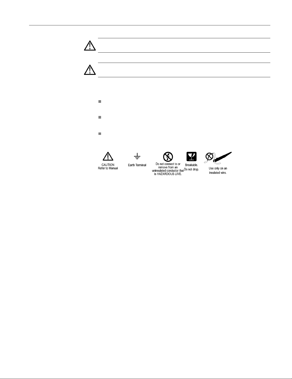
Symbols and Terms on the
Product
These terms may appear on the product:
DANGER indicates an injury hazard immediately accessible as you read
the marking.
WARNING indicates an injury hazard not immediately accessible as you
read the marking.
CAUTION indicates a hazard to property including the product.
The following symbol(s) may appear on the product:
P6022 Instruction Manual v
Page 12

Service Safety Summary
Service Safet
y Summary
Only qualifie
Safety Summary and the General Safety Summary before performing any service
procedures.
Do Not Service Alone. Do not perform internal service or adjustments of this
product unless another person c apable of rendering first aid and resuscitation is
present.
Disconnect Power. To avoid electric shock, switch off the instrument power, then
disconnect the power cord from the mains power.
Use Care When Servicing With Power On. Dangerous voltages or currents may
exist in
disconnect test leads before removing protective panels, soldering, or replacing
components.
To avoid electric shock, do not touch exposed connections.
d personnel should perform service procedures. Read this Service
this product. Disconnect power, remove battery (if applicable), and
vi P6022 Instruction Manual
Page 13

Compliance Information
This section lists the safety and environmental standards with which the
instrument complies.
Safety Compliance
EC Declaration of
Conformity – Low Voltage
Additional Compliances
Equipment Type
Safety Class
Compliance was demonstrated to the following specification as listed in the
Official Journal of the European Communities:
Low Voltage Directive 2006/95/EC.
EN 61010-1: 2001. Safety requirements for electrical equipment for
measurement control and laboratory use.
EN 61010-2-032: 2002. Particular requirements for handheld current clamps
for electrical measurement and test equipment.
IEC 61010-1: 2001. Safety requirements for electrical equipment for
measurement, control, and laboratory use.
IEC 61010-2-032: 2002. Particular requirements for handheld current clamps
for electrical measurement and test equipment.
Test and measuring equipment.
Class1–groundedproduct.
Pollution Degree
Description
P6022 Instruction Manual vii
A measure of the contaminants that could occur in the environment around
and within a product. Typically the internal environment inside a product is
considered to be the same as the external. Products should be used only in the
environment for which they are rated.
Pollution Degree 1. No pollution or only dry, nonconductive pollution occurs.
Products in this category are generally encapsulated, hermetically sealed, or
located in clean rooms.
Pollution Degree 2. Normally only dry, nonconductive pollution occurs.
Occasionally a temporary conductivity that is caused by condensation must
be expected. This location is a typical office/home environment. Te mporary
condensation occurs only when the product is out of service.
Pollution Degree 3. Conductive pollution, or dry, nonconductive pollution
that becomes conductive due to condensation. These are sheltered locations
where neither temperature nor humidity is controlled. The area is protected
from direct sunshine, rain, or direct wind.
Page 14

Compliance Information
Pollution Degree
Pollution Degr
conductive dust, rain, or s now. Typical outdoor locations.
Pollution Degree 2 (as defined in IEC 61010-1). Note: Rated for indoor use only.
ee 4. Pollution that generates persistent conductivity through
viii P6022 Instruction Manual
Page 15

Compliance Information
Environmenta
l Considerations
Product End-of-Life
Handling
Restriction of Hazardous
Substances
This section provides information about the environmental impact of the product.
Observe the following guidelines when recycling an instrument or component:
Equipment Recycling. Production of this equipment required the extraction and
use of natural resources. The equipment may contain substances that could be
harmful to
end of life. In order to avoid release of such substances into the environment and
to reduce the use of natural resources, we encourage you to recycle this product
in an appropriate system that will ensure that most of the materials are reused or
recycled appropriately.
This product has been classified as Monitoring and Control equipment, and is
outside the scope of the 2002/95/EC RoHS Directive.
the environment or human health if improperly handled at the product’s
This sym
Union requirements according to Directives 2002/96/EC and 2006/66/EC
on waste electrical and electronic equipment (WEEE) and batteries. For
informa
Tektronix Web site (www.tektronix.com).
bol indicates that this product complies w ith the applicable European
tion about recycling options, check the Support/Service section of the
P6022 Instruction Manual ix
Page 16

Compliance Information
x P6022 Instruction Manual
Page 17

Operator Information
This manual describes the P6022 current probe with passive termination, and
provides information about making measurements with the probe.
Description
The P6022 current probe converts an alternating current waveform to a voltage
that can be
accurate current measurements over a wide range of frequencies, and allows you
to measure current without breaking the circuit.
The P6022 probe is compatible with general-purpose ground-referenced
oscilloscopes having a 1 MΩ input impedance. The P6022 probe comes with a
passive termination that matches oscilloscope and probe impedance, optimizes the
probe performance, and provides two sensitivity settings.
The P6022 probe comes with a 5-foot cable, termination, and 6” ground lead.
displayed and measured on an oscilloscope display. It provides
Figure 1: P6022 probe, termination, and ground lead
P6022 Instruction Manual 1
Page 18

Operator Information
Installation
This section describes both attaching the probe to an oscilloscope and using the
standard accessories with the probe.
To ensure the best performance from your probe/oscilloscope measurement
system, check that the probe and oscilloscope are appropriately matched. The
oscilloscope inputs should use BNC connectors, and have an impedance of 1 MΩ.
Figure 2: Connecting the probe and termination to the oscilloscope
2 P6022 Instruction Manual
Page 19

Operator Information
Attaching the Probe
and Termination to an
Oscilloscope
1. Connect the ter
2. Connect the termination box male BNC end to a ground-referenced
oscilloscope
WAR N ING. To avoid electric shock and possible injury, do not apply any voltage
above earth ground potential to the probe common lead (do not float the common).
The exposed metal on the probe output cable and termination box is electrically
connected to the probe common lead and therefore is at the same potential.
This probe is intended for use with ground-referenced oscilloscopes only. Do
not float the oscilloscope by removing or isolating the ground pin from the AC
power cord.
Do not use this probe with any equipment with floating inputs, including the
TPS2000 or THS700 series oscilloscope.
3. When you make high frequency measurements, snap the ground lead to the
probe transformer post and attach the alligator clip directly to RF ground to
improve EMI rejection at high frequencies (2 MHz and above). This reduces
ng and helps to bypass capacitively-coupled RF currents which can flow
ringi
into the probe cable.
mination box female BNC end to the P6022 probe output cable.
.
WAR N ING. To avoid potential shock and damage to the probe, do not disconnect
the probe termination and leave the P6022 clamped around the conductor when
measuring high currents. Leaving the probe cable unterminated can cause a high
voltage to develop in the secondary winding which may pose a shock hazard
damage the current probe transformer. Never disconnect the probe from the
and
termination when the probe is connected to a live conductor.
ver disconnect the probe from the termination when the probe is connected to
Ne
a live conductor.
P6022 Instruction Manual 3
Page 20

Operator Information
Using th e Standard
Accessories
Your P6022 prob
This instruction manual — Read these instructions to familiarize yourself
with the featu
6-inch ground lead —Usethe6-inchgroundleadtogroundtheshield
around the p
move the ground connection closer to the circuit you are measuring, thereby
improving high frequency response. The ground lead clips onto the ground
connector on the bottom of the probe as shown.
Please refer to the parts list for part numbers. (See page 32, Replaceable
Mechanical Parts.)
e is shipped with the following accessories:
res, specifications, and operation of the P6022 current probe.
robe transformer at the probe end of the cable. This allows you to
4 P6022 Instruction Manual
Page 21

Operator Information
Operating Con
Features and
siderations
Controls
The information in this section will help you make the most effective use of your
P6022 probe.
Sensitivity Control — The P6022 termination has a control that allows you
to select probe sensitivity. The switch has two positions: 1 mA/mV and
10 mA/mV. When the control is in the 1 mA/mV position, the oscilloscope
displays 1
control is in the 10 mA/mV position, the oscilloscope displays 1 mV for every
10 mA of current in the circuit under test.
You can set vertical scale on the oscilloscope to any scale factor, as determined
by the signal amplitude. To calculate the overall vertical scale factor for the
oscilloscope, probe, and termination, multiply the termination sensitivity
control setting by the vertical scale factor of the oscilloscope. For example, if
the termination control is set to the 10 mA/mV position, and the oscilloscope
to a ver
200 mA/division.
mV for every 1 mA of current in the circuit under test. When the
tical scale of 20 mV/division, the overall scale factor is 10 X 20, or
ProbeSlideSwitch— The slide switch on the probe has three positions:
open, closed, and locked. Use your thumb to move the probe slide switch.
The switch is spring-loaded so that it automatically moves from the open to
closed positions.
P6022 Instruction Manual 5
Page 22

Operator Information
To Use the Probe
WARNING. To reduce risk of electric shock, use only insulated conductors with
these probes on circuits with voltages above 30 Vrms, 42 Vpk, or 60 VDC. These
probes are not rated for bare wire voltages above 30 Vrms, 42 Vpk, or 60 VDC.
CAUTION. Toreduceriskoffire, do not connect or disconnect the current probe to
or from a live, uninsulated conductor. The core is not insulated. Always remove
power before you connect or disconnect the probe to or from bare conductors.
NOTE. An insulated conductor is any conductor that is surrounded by an
insulating material that is capable of isolating the voltage present on the
conductor. Lacquer coatings like those typically found on transformer windings
do not pr
lacquer coating can be easily nicked or damaged, which compromises the
insulating capabilities of the lacquer coating.
CAUTION. To prevent damage to the probe, do not drop the probe, subject it
to physical shock or rapid temperature changes, and do not insert insulated
conductors larger than 2.6 mm into the probe jaw or damage may result. If the
slider will not close around the conductors, do not force the slide closed, either
reduce the number of conductors, or use a smaller conductor if possible without
exce
ovide sufficient, reliable insulation for use with current p robes. The
eded the amperage rating of the wire.
.
1. Pull the slide switch toward you and hold the switch in position.
2. Place the conductor-under-test inside the exposed transformer core. The
arrow on the transformer end of the probe indicates conventional current
w. If you place the probe on the conductor so that the arrow on the probe
flo
matches conventional current flow through the conductor, orientation of the
displayed waveform will be correct.
3. Release the switch, allowing the probe to close.
4. Lock the slide switch. To lock the switch, push it firmly toward the
transformer (the switch will move only about 1/8th inch). Locking the
switch assures maximum contact between the two halves of the transformer
secondary. The conductor now becomes the primary of the transformer.
(When measuring current, always check that the probe slide switch is moved
completely forward into the locked position.)
6 P6022 Instruction Manual
Page 23

Operator Information
Insertion Impedance
Minimizing Loading Effect
Increasing Probe
ivity
Sensit
When you insert
are measuring. This additional impedance affects signals; this is particularly
important if you are m easuring fast rise times. The equivalent circuit with
additional impedance introduced by the P6022 is shown below.
Figure 3: I
To minimize the loading effect of the probe, clamp it at the low or ground end
of a comp
signal interference.
You can increase the current sensitivity of the probe by increasing the number
of time
through the probe twice (a two-turn primary winding), the secondary current is
doubled, because the ratio of current in a transformer is inversely proportional
to the turns ratio.
nsertion impedance of the probe
onent lead when possible. This method also minimizes noise or stray
s a conductor passes through it. For example, if the conductor loops
a conductor into the probe, you add impedance to the circuit you
For example, suppose you set the termination sensitivity to 1 mA/mV and the
oscilloscope vertical scale to 10 mV/division. Ordinarily, this would result in the
equivalent of 1 X 10, or 10 mA/division. However, if the conductor is looped
through the probe twice, the vertical scale is divided by two, resulting in the
uivalent of 5 mA/division.
eq
Looping the conductor twice effectively doubles vertical sensitivity; however,
pedance from the probe winding is also reflected into the circuit being
im
measured. This impedance varies as the square of the number of loops. This
additional impedance affects signals; this effect is particularly important when
you are measuring high-frequency current waveforms or waveforms with fast
rise times.
P6022 Instruction Manual 7
Page 24

Operator Information
Probe Shielding
The P6022 probe
However, strong fields can interfere with the current signal being measured. If you
suspect that an external field is interfering with your measurement, remove the
probe from the conductor, but keep it in the same location as when you made the
suspect measurement. If a signal still appears on the oscilloscope, try to measure
the conductor current at a point farther from the location of the magnetic field.
If you must measure current in the presence of a strong magnetic field, you can
minimize its interference by using two current probes and a differential-input
oscillosc
1. Connect the probes (with termination) to the positive and negative inputs of
2. Clamp one probe around the conductor whose current you wish to measure.
3. Place the other probe as close as possible to the first. Ensure that its slide
4. Set the oscilloscope to subtract the component of the signal that is common to
5. Adjust the positions of the probes for best results. It may be difficult to
ope. To do so, follow these steps.
the oscil
switch is completely closed, without a conductor inside it.
both probes.
eliminate the undesirable signal completely, due to differences between the
s or their terminations.
probe
is shielded to minimize the effect of external magnetic fields.
loscope.
Droop
The flat-top response of any AC current probe displays a certain amount of droop.
This is caused by probe inductance loading the source impedance, causing an L/R
onential decay. For short pulse widths, the response looks nearly flat. The
exp
amount of droop can be calculated from the following relationship:
roop = 200 (π)Tf
%D
where:
T = pulse duration
f = lower 3 dB frequency of probe
8 P6022 Instruction Manual
Page 25

Service Information
Service Infor
mation
Warranted Characteristics
This sectio
P6022 Current Probe. Included are warranted electrical and environmental
characteristics.
Warranted characteristics are described in terms of quantifiable performance
limits that are warranted.
The warranted electrical characteristics listed apply under the following
conditions:
Table 1: Warranted electrical characteristics
Characteristic Information
Sensitivity setting 1 mA or 10 mA for each mV at oscilloscope
Midband accuracy
Bandwidth (-3 dB) (with BW >300 MHz oscilloscope)
n lists the various warranted characteristics that describe the
The probe and instrument with which it is used must have been calibrated at
anambienttemperatureofbetween+20°Cand+30°C(68°Fto86°F).
The probe and instrument must be in an environment whose limits are
described in the environmental specifications table. (See Table 2.)
input, selected by termination sensitivity
control
±3%
1mA/mV
10 mA/mV
8.5 kHz to 100 MHz
935 Hz to 120 MHz
Table 2: W arranted environmental characteristics
Characteristic Information
Temperature range:
Operating
Nonoperating
Altitude
Operating To 2,000 m (6,561 ft)
Nonoperating
P6022 Instruction Manual 9
0 °C to +50 °C (32 °F to 122 °F)
–40 °C to +65 ° C (–40 °F to 149 °F)
To 15,240 m (50,000 ft)
Page 26

Service Information
Table 3: Maximu
m ratings
Characteristic Information
Maximum continuous (CW) current
1mA/mV
10 mA/mV
Maximum pul
se current
Refer to figure for frequency derating curves
(See Figure 4.)
ve between 10 kHz and 10 MHz
sine wa
6A
p-p
6A
sine wave between 3 kHz and 10 MHz
p-p
100 A peak, not to exceed 9(A · ms) or
2A
. An (A · s) product greater than 9
RMS
(A · ms) redu
ces probe output to zero due
to core saturation
Maximum vo
ltage on bare wire
1
Insulated wire only for voltages above
30 VAC, 42 Vpk, 60 VDC.
1
An insulated conductor is any conductor that is surrounded by an insulating material that is capable of isolating
the voltage present on the conductor. Lacquer coatings like those typically found on transformer windings do not
provide sufficient, reliable insulation for use with current probes. The lacquer coating can be easily nicked or
damaged, which c ompromises the insulating capabilities of the lacquer coating.
Figure 4: Probe and termination input current vs. frequency derating
10 P6022 Instruction Manual
Page 27

Service Information
Typical Chara
cteristics
This section lists the various typical characteristics that describe the P6022
Current Probe. Included are typical electrical and mechanical characteristics.
Typical characteristics are described in terms of typical or average performance.
Typical characteristics are not warranted.
Table 4: El
Characteristic Information
Tilt
Maximum DC without saturation
Signal delay, 5-foot probe with termination
Insertion impedance
Rise time
Step response
Aber
sensitivity setting.)
ectrical characteristics
1mA/mV
10 mA/mV
1mA/mV
10 mA/mV
rations (probe and termination at either
4% or less within 1ms of step
4% or less within 10ms of step
0.2 A
Approximately 9 ns
0.03 Ω or less at 1 MHz, increasing to 0.2 Ω
at 120 MHz
or less
s
≤3.2 n
≤2.9 ns
se the oscilloscope input capacitance
Becau
becomes a part of the termination network,
the step response will vary with different
lloscopes
osci
peak-to-peak within 25 ns of step;
≤15%
≤2% peak-to-peak thereafter
Table 5: Mechanical characteristics
Characteristic Information
Probe cable length
Net weight:
Probe and 5-foot cable
Termi n a tion
Termination L 3.47", 88 mm
Probe body L 6.0", 152 mm
Maximum conductor diameter 0.11", 2.79 mm
5 ft, 1.5 m
2.5 oz, ≈71 gm
1.7 oz, ≈48 gm
W 1.10", 28 mm
H 0.86", 22 mm
W0.4",10mm
H0.6",15mm
P6022 Instruction Manual 11
Page 28

Service Information
Circuit D escr
Current Probe
iption
This section describes the circuits in the P6022 current probe and termination.
The P6022 current probe consists of a current transformer mounted in the nose of
the probe head case, an impedance-matching network, and an internal switch to
disconnect the transformer shield from ground.
The transformer contains a two-section, U-shaped ferrite core. One section is
stationary; the other is mechanically movable to permit closing the core around
the conductor being measured. The conductor under test forms a one-turn primary
winding f
core are the secondary windings. The circuitry between the transformer and the
coaxial cable corrects any differences in level between the pulses induced in the
windings of the secondary, and matches the balanced probe winding to the cable.
As indicated on the probe body, the turns ratio of the P6022 is 50:1. This refers to
the number of windings in the secondary of the probe transformer.
The probe transformer is shielded to eliminate interference from outside signals.
To eliminate the possibility of creating a short circuit from this shield to the
conductor being measured, the slide switch disconnects the ground from the
shield when you open the sliding portion of the probe to connect or remove it
from
or the transformer; the windings around the stationary portion of the
a conductor.
Termination
The P6022 termination consists of an impedance-matching network to terminate
the coaxial cable, and a voltage divider that is switched in by a sensitivity control
change the sensitivity by a factor of five. When the control is in the 1 mA/mV
to
position, a 10 mA current signal in the conductor under test induces a 10 mV
signal at the output of the termination. (This assumes that the termination is
connectedtoa1MΩ input oscilloscope.)
When the sensitivity control is in the 10 mA/mV position, a 10 mA current signal
is attenuated to induce a 1 mV signal at the output of the termination.
12 P6022 Instruction Manual
Page 29

Service Information
Probe Perform
ance
WAR N ING. This probe should be serviced only by qualified service personnel.
To av oid pe rs
signal source before attempting to adjust or service the probe.
Do not servi
that is attached to a s ignal or power source, do so only when another person
capable of rendering first aid and resuscitation is present.
This section provides procedures to check the performance of the P6022 probe,
or to calibrate it. These procedures require the equipment listed. (See Table 6
on page 14.) Specifications given are the minimum necessary for accuracy.
If equipment is substituted, it must meet or exceed the specifications of the
recommended equipment. Test equipment is assumed to be correctly calibrated
and ope
Also, if equipment is substituted, control settings or equipment setup may need
ltered. For detailed operating instructions for the test equipment, refer to
to be a
the instruction manual for each unit.
ure measurement accuracy, check the performance of the probe and
To ens
termination whenever you begin using them with a different oscilloscope input,
especially when you have changed input capacitance. Recalibrate the probe if
necessary. Also check the calibration of the probe and termination every 1000
hours of operation, or every six months if they have been used infrequently.
onal injury and damage to the probe, remove the probe from any
ce electrical equipment alone. If you must service or adjust equipment
rating within the given specifications.
Before calibrating the probe, inspect and clean it thoroughly. (See page 24,
Maintenance.) Dirty or worn mating surfaces between the transformer and the lid
can degrade low-frequency response. Clean these surfaces if necessary.
Calibration procedures can also be used as performance checks by completing all
steps except those that adjust the probe. This checks the probe and termination
o the original performance standards without requiring you to remove the
t
termination cover or make internal adjustments.
P6022 Instruction Manual 13
Page 30

Service Information
Table 6: Equipm
Item
Oscilloscope
Calibration generator
ent list
Characteristic
Bandwidth
Vertical sen
sitivity
Measurement functions
Fast rise ti
me
Description Recommended eq
DC to ≥300 MHz
1 mV/div
Amplitude a
Rise time ≤1
1V
Sinewave voltage 5 V
veraging
ns
into 50 Ω
P-P
into 50 Ω (100 mA),
P-P
935 Hz to 120 MHz
ness
ts or better
Digital m
ultimeter (DMM)
1.5X, flat
RMS ACV 5 1/2 digi
50 kHz ≤0.5%
Adapter
BNC "T"
Coaxial cables (2) 36-inch, 50 Ω precision
r
Adapte
Fixtur
e
BNC-to-dual banana
Current probe, calibration
uipment
TDS 303X, or TDS 305X
Wavetek 910
0withoption
100:250 or Tektronix PG 506A
Wavetek 91
00 with option
100:250, or Tektronix SG
5030, SG 503
Keithley 2000, or HP 3458A
ix part number
Tektr o n
103-0030-XX
ix part number
Tektr o n
012-0482-XX
nix part number
Tektr o
103-0090-XX
nix part number
Tektr o
067-0559-XX
Photocopy the Test Record and use it to record the performance test results. (See
Table 9 on page 21.)
14 P6022 Instruction Manual
Page 31

Service Information
Performance V
Check Midband Accuracy
erification
Refer to the illustration below when making equipment connections.
Figure 5: Midband accuracy test setup
P6022 Instruction Manual 15
Page 32

Service Information
1. Set the P6022 te
rmination sensitivity to 1 mA/mV.
2. Connect the Leveled Sinewave Output of the calibration generator to a BNC
"T". Connect o
ne branch of the BNC "T" to the calibration fixture. Connect
the other branch of the BNC "T" to the DMM input u sing a BNC-to-dual
banana adapter.
3. Set the DMM to ACV (autorange).
4. Set the Leve
an amplitude of 5 V
5. Measure an
led Sinewave Output of the calibration generator to 50 kHz and
.
pp
d record the DMM output as M1.
6. Disconnect the coax cable from the BNC-to-dual banana adapter.
7. Connect the P6022 termination and probe to the BNC-to-dual banana adapter.
8. Connect the probe to the calibration fixture.
9. Record the DMM output as M2.
10. Calculate the % of error.
11. Record the results in the test record and compare the results against the
midband accuracy specification. (See Table 1 on page 9.)
12. Set the P6022 termination sensitivity to 10 mA/mV.
13. Record the DMM output as M3.
14. Calculate the % of error:
15. Record the results in the test record and compare the results against the
midband accuracy specification.
16 P6022 Instruction Manual
Page 33

Service Information
Check Low Frequency
Response
Refer to the set
up diagram when making equipment connections. (See Figure 5
on page 15.)
1. Connect the calibration fixture to the Leveled Sinewave Output of the
calibration generator.
2. Connect the BNC-to-dual banana adapter to the input of the DMM.
3. Connect the P6022 termination and probe to the BNC-to-dual banana adapter
that is connected to the DMM.
4. Set the P6022 termination sensitivity to 1 mA/mV.
5. Set the DMM to ACV (autorange).
6. Set the Leveled Sinewave Output of the calibration generator to 50 kHz and
an amplitude of 5 V
.
pp
7. Connect the probe to the calibration fixture.
8. Enable the Leveled Sinewave Output of the calibration generator.
9. Measure and record the DMM output as M1 in the table below. (See T
able 7
on page 18.)
10. Set the Leveled Sinewave Output of the calibration generator to 8.5 kHz.
11. Measure and record the DMM output as M2 in the table below. (See Table 7.)
12. Calculate the low frequency bandwidth ratio:
13. Record the results in the test record and compare the results against the low
frequency specification. (See Table 1 on page 9.)
14. Set the P6022 termination sensitivity to 10 mA/mV.
15. Set the Leveled Sinewave Output of the calibration generator to 50 kHz and
an amplitude of 5 V
.
pp
16. Measure and record the DMM output as M3 in the table below. (See Table 7.)
17. Set the Leveled Sinewave Output of the calibration generator to 935 Hz.
18. Measure and record the DMM output as M4 in the table below. (See Table 7.)
19. Calculate the low frequency bandwidth ratio:
20. Record the results in the test record and compare the results against the low
frequency specification.
NOTE. Dirty or worn mating surfaces between the transformer and the lid degrade
the low-frequency response. Clean them if necessary. (See page 24, Maintenance.)
P6022 Instruction Manual 17
Page 34

Service Information
Table7: P6022l
Probe
sensitivity
1mA/mV
10 mA/mV
ow frequency bandwidth measurements
Probe
sensitivity M1 M2 M2/M1 M3 M4 M4/M3
50 kHz
8.5 kHz
50 kHz
935 Hz
Check High Frequency
Bandwidth
Refer to the figure below when making equipment connections.
Figure 6: High frequency bandwidth test setup
18 P6022 Instruction Manual
Page 35

Service Information
1. Set the P6022 te
rmination sensitivity to 1 mA/mV.
2. Connect the calibration fixture to the Leveled Sinewave Output of the
calibration g
enerator.
3. Connect the P6022 termination and probe to CH1 of the oscilloscope.
4. Set the oscilloscope Vertical Deflectionto20mV/div.
5. Set the oscilloscope Horizontal Scale to 10 μs/div.
6. Set the oscilloscope Auto Measurement to display "Amplitude".
7. Set the Leveled Sinewave Output of the calibration generator to 50 kHz and
an amplitude of 5 V
.
pp
8. Connect the probe to the calibration fixture.
9. Enable t
he Leveled Sinewave Output of the calibration generator.
10. Measure and record the oscilloscope "amplitude" Auto Measurement as M1 in
le. (See Table 8 on page 20.)
the tab
11. Set the oscilloscope Horizontal Scale to 4 ns/div o r 5 ns/div.
12. Set the Leveled Sinewave Output of the calibration generator to 100 MHz.
13. Measure and record the oscilloscope amplitude Auto Measurement as M2 in
the table.
14. Calculate the high frequency bandwidth ratio:
P6022 Instruction Manual 19
Page 36

Service Information
15. Record the resu
lts in the test record and compare the results against the high
frequency specification. (See Table 1 on page 9.)
16. Set the P6022 t
ermination sensitivity to 10 mA/mV.
17. Set the oscilloscope Vertical Deflectionto2mV/div.
18. Set the oscilloscope Horizontal Scale to 10 μs/div.
19. Set the Leveled Sinewave Output of the calibration generator to 50 kHz and
an amplitude of 5 V
.
pp
20. Measure and record the oscilloscope amplitude Auto Measurement as M3 in
the table.
21. Set the oscilloscope Horizontal Scale to 4 ns/div or 5 ns/div.
22. Set the Leveled Sinewave Output of the calibration generator to 120 MHz.
23. Measure and record the oscilloscope amplitude Auto Measurement as M4 in
the table.
24. Calculate the high frequency bandwidth ratio:
25. Record the results in the test record and compare the results against the high
frequency specification.
When you are done, disconnect all test equipment and replace the termination
cover.
Table 8: High frequency bandwidth measurements
Leveled
Sinewave
Output
frequency
Probe
sensitivity
1 mA/mV 20 mV/div
10 mA/mV 2 mV/div
Vertical
Deflection
Horizontal
Scale
10 μs/div
4or
5ns/div
10 μs/div
4or
5ns/div
(calibration
generator) M1 M2 M2/M1 M3 M4 M4/M3
50 kHz
100 MHz
50 kHz
120 MHz
20 P6022 Instruction Manual
Page 37

P6022 Test Record
Table 9: P6022 test record
Service Information
Photocopy this form and use it to record the performance test results.
Instrument Serial Number:
Temperature:
Date of Calibration:
Performance test Range, mA/mV Minimum Measured/calculated Maximum
1
10
Bandwidth, Low
Frequency Response
Bandwidth, High
Frequency Response
1 0.707
10 0.707
1 0.707
10 0.707
Certificate Number:
Relative Humidity %:
Technician:
-3% +3%Midband Accuracy (% Error)
-3% +3%
—
—
—
—
P6022 Instruction Manual 21
Page 38

Service Information
Adjustment Procedure
Preparation
If the probe does not pass the performance verification procedure or you want
to optimize the performance of the probe, perform the following adjustment
procedure:
1. Insert a small screwdriver between the cover and the termination near the part
number, and gently pry up only the top cover from the P6022 termination by
twisting the screwdriver. Leave the bottom cover on, as it must remain in
place when
ever the termination is in use.
2. Set up the oscilloscope as described below:
Control Setting
Vertical mode
Horizontal mode Main
Trigger source
Trigger coupling
Trigger mode Peak-to-peak, auto
Trigger slope Positive
Trigger level As required
Ch 1 coupling DC
Volts/division
Time/division 4 ns or 5 ns (depending on oscilloscope type)
Averages 5 to 10
CH 1
CH 1
AC
2mV
NOTE. When using a Wavetek 9100 calibrator with the scopecal option, no other
calibrators are required. The following setups are generic with nominal settings
indicated for the major adjustment steps.
22 P6022 Instruction Manual
Page 39

Service Information
Adjust Abe rrat
ions
CAUTION. To avoid damaging the probe, do not disconnect the probe termination
when measuring high currents. Leaving the probe cable unterminated can cause a
high voltage to develop in the secondary winding which may damage the current
probe transformer.
1. Connect the current probe calibration fixture to the fast rise output of the
calibration generator.
2. Set the fast rise output to maximum (1 V
)
pp
3. Connect the P6022 cable BNC connector to the termination.
4. Connect the P6022 termination to the oscilloscope Ch 1 input.
5. Set the P
6022 termination sensitivity to 1 mA/mV.
6. Connect the probe to the current probe calibration fixture. The figure below
shows t
he proper probe orientation to the current probe calibration fixture.
Figure 7: Connecting the probe to the calibration fixture
7. Adjust C28 and C29 (in the termination), and then R10 (through the hole
in the probe body) to minimize aberrations and achieve the best flat-top
response. The adjustment locations are shown in the illustration. (See
Figure 8 on page 24.)
P6022 Instruction Manual 23
Page 40

Service Information
Mainten
ance
NOTE. The R10 ad
10 mA/mV termination setting along with the high frequency response. Readjust
the h igh frequency response if it fails.
Figure 8: Location of probe and termination adjustments
justment affects the aberrations of both the 1mA/mV and
Clean
ing
The information in this section will help you maintain your probe for a long
service life.
To clean the probe body, use a soft cloth dampened with water. To clean the core,
open the jaw and clean the exposed core surfaces with a cotton swab dampened
with isopropyl alcohol.
ION. To prevent damage to probe materials, avoid using chemicals that
CAUT
contain benzene, benzine, toluene, xylene, acetone, or similar solvents.
Do not immerse the probe in liquids or use abrasive cleaners.
Do not lubricate the jaws mating surfaces. Any lubricant between the core pieces
should be removed with a recommended solvent.
Do not use a petroleum based lubricant on the plastic. If the plastic slide assembly
requires lubrication, use a silicone-based grease sparingly.
When cleaning the probe, look for any excessive wear of the slide parts that might
cause the probe to operate improperly. Dirty or worn mating surfaces between
the transformer and the lid can degrade low-frequency response. Clean these
surfaces if necessary.
24 P6022 Instruction Manual
Page 41

Service Information
Disassembling the Probe
Use the followi
will need a low power soldering iron with a fine point. Work over a smooth, clean
surface so that you can easily find any small pieces that may drop. (See Figure 9.)
CAUTION. To avoid degrading the performance of the probe, do not touch the
polished mating surfaces of the transformer after cleaning.
ng procedure to disassemble the probe for cleaning or repair. You
Figure 9: Disassembling the probe
P6022 Instruction Manual 25
Page 42

Service Information
1. Hold the probe h
2. Pull the strain relief boot back over the cable. Lightly rock the strain relief
boot from side
3. Be careful, there is a spring-loaded retainer and a small ball bearing you are
about to exp
4. Slowly lift the upper half of the probe body slightly at the cable end and push
the assembl
5. Remove the small ball bearing from the detent in the slide switch.
6. Lift the back of the return spring retainer out of the holder.
7. Remove the slide switch, spring retainer, and the top of the transformer as a
unit. Notice the orientation of the movable portion of the transformer in the
slide.
CAUTIO
enough heat to separate or attach connections. Excess heat may cause irreparable
damage to the circuit board.
8. Desolder the ground connection on the circuit board. (See Figure 9 on
N. To prevent damage to the circuit board when desoldering, use only
page 25.)
orizontally with the slide switch up.
to side as you pull back on it.
ose.
y forward over the nose and off.
9. Lift the circuit board, transformer, and cable out of the probe body as a unit.
Be careful, the cable connection to the board is fragile and may break if not
handled gently.
10. To reassemble the probe, reverse the procedure above.
When replacing the slide switch, spring retainer, and transformer top as a unit,
push the slide switch contacts gently inside the sides of the bottom housing.
26 P6022 Instruction Manual
Page 43

Service Information
Repairing the Probe
Repairing the Termination
To ma ke repairs
previous section. If you need to solder on the circuit board, use a minimum of
heat and observe normal circuit board procedures.
If you need to replace the current transformer, replace the entire assembly
including the other half of the transformer core mounted in the slide switch. The
transformer halves are matched at the factory before shipment.
Repairing the termination can consist of replacing either the connectors or the
circuit board. These tasks are described below.
Replacing the Connectors. To replace the connectors, follow these steps:
1. Insert a small screwdriver between the cover and the termination near the part
number, and gently pry up the plastic snap-on cover from the termination.
2. Using a heat sink, unsolder the leads from the defective connector.
3. Unscrew and remove the defective connector.
4. Replace the defective connector with the new one.
5. Screw
6. Align the switch with the slider in the front cover and replace the front cover.
inside the probe body, disassemble the probe as described in the
and solder the new connector back in place.
Replacing the Circuit Board. To replace the c i rcuit board, follow t hese steps:
1. Rem
2. Using a heat sink, unsolder the leads from the connectors.
3. Unscrew the two screws from the back of the circuit board.
4. Remove the circuit board from the termination and repair it as you require,
5. Replace the circuit board by reversing the above procedure.
6. Align the switch with the slider in the front cover and replace the front cover.
ove the plastic snap-on covers from the front and back of the termination.
being careful to use a minimum of heat and observe normal circuit board
procedures.
P6022 Instruction Manual 27
Page 44

Replaceable Electrical Parts
Replaceable Electrical Parts
Parts Orderin
g Information
Replacement parts are available from or through your local Tektronix, Inc. service
center or representative.
Changes to Tektronix instruments are sometimes made to accommodate improved
components as they become available and to give you the benefit of the latest
circuit im
the following information in your order:
If a part you order has been replaced with a different or improved part, your local
Tektronix service center or representative will contact you concerning any change
in the part number.
Change information, if any, is located at the rear of this manual.
provements. Therefore, when ordering parts, it is important to include
Part numb
Instrument type or model number
Instrument serial number
Instrument modification number, if applicable
Using the Replaceable Parts List
er
em Names
It
Abbreviations
List of Assemblies
The tabular information in the Replaceable Parts List is arranged for quick
retrieval. Understanding the structure and features of the list will help you find the
all the information you need for ordering replacement parts.
In the Replaceable Parts List, an Item Name is separated from the description by
a colon (:). Because of space limitations, an Item Name may sometimes appear
as incomplete. For further Item Name identification, U.S. Federal Cataloging
andbook H6-1 can be used where possible.
H
Abbreviations conform to American National Standards Institute (ANSI)
standard Y1.1
A list of assemblies can be found at the beginning of the electrical parts list. The
assemblies are listed in numerical order. When the complete component number
of a part is known, this list will identify the assembly in which the part is located.
28 P6022 Instruction Manual
Page 45

Replaceable Electrical Parts
Component Number
(column 1 of the parts list)
Tektroni
x Part Number
(column 2 of the parts list)
Serial Number (columns 3
&4ofthepartslist)
Name & Description
(column five of the parts
list)
The circuit com
illustrations. Each diagram and circuit board illustration is clearly marked with
the assembly number. Assembly numbers are also marked on the mechanical
exploded views located in the mechanical parts list. The component number is
obtained by adding the assembly number prefix to the circuit number.
The electrical parts list is divided and arranged by assemblies in numerical
sequence (e.g., assembly A1 with its subassemblies and parts, precedes assembly
A2 with its subassemblies and parts).
Chassis-mounted parts have no assembly number prefix and are located at the
end of the electrical parts list.
Indicates part number to be used when ordering replacement part from Tektronix.
Column three (3) indicates the serial number at which the part was first used.
Column four (4) indicates the serial number at which the part was removed. No
serial number entered indicates part is good for all serial numbers.
In the parts list, an item name is separated from the description by a colon (:).
Because of space limitations, an item name may sometimes appear as incomplete.
For further item name identification, the U.S. Federal Catalog handbook H6-1
can be utilized where possible.
ponent number appears on the diagrams and circuit board
P6022 Instruction Manual 29
Page 46

Replaceable Electrical Parts
Table 10: Repla
Component
number
A1 670-1112-00
A2 011-0106-00
A1 670-1112-00
A1C10
A1L10 120-0285-0
A1R10 311-0605-00
A1T1 120-0603-00
A1T14 120-0286-
A2 011-0106-00
A2C21
A2C26
A2C28
A2C29
A2C37
A2L26 108-0409-01
A2L28 108-0523-00
A2L33 108-03
A2R26 321-0014-00
A2R28 317-0201-00
A2R29 321-0
A2 R31 321-0 210- 00
A2R33 321-0078-00
4
A2R3
A2R35 321-0003-00
A2R36 317-0270-00
37
A2R
A2R39 317-0240-00
A2SW30
ceable electrical parts
Tektronix part
number
283-0157-00
283-0066-00
-00
281-0629
281-0123-00
281-0123-00
2-00
283-116
95-00
751-06
0002-00
321-
-0300-00
317
260-0723-00
Serial number
effective/ds
0
00
cont
Name & descrip
CIRCUIT BD ASSY:PROBE
TERMN,COAXIAL:P6022
CIRCUIT BD AS
CAP,FXD,CER DI:7PF,5%,50V
XFMR,TOROID:4 TURNS,SINGLE
RES,VAR,NO
TRANSFORMER,CUR:
XFMR,TOROID:2 TURNS,BIFILAR,3S76
TERMN,COA
CAP,FXD,CER DI:2.5PF,+/-0.5PF,200V
CAP,FXD,CER DI:33PF,5%,600V
CAP,VAR,
CAP,VAR,CER DI:5-25PF,100V
CAP,FXD,CERAMIC; MLC;39PF,5%,50V,C0G/NPO;RADIAL SQUARE
:FIXED,17.5UH
COIL,RF
XFMR,TOROID:FIXED,160NH
COIL,RF:FIXED,64UH
D,FILM:13.7 OHM,1%,0.125W,TC=T0
RES,FX
RES,FXD,CMPSN:200 OHM,5%,0.125W
RES,FXD,FILM:50 OHM,0.25%,0.125W,TC=T9
XD,FILM:1.50K OHM,1%,0.125W,TC=T0
RES,F
RES,FXD,FILM:63.4 OHM,1%,125W,TC=T0
RES,FXD,FILM:10.2 OHM,1%,0.125W,TC=T0
FXD,FILM:10.5 OHM,1%,0.125W
RES,
RES,FXD,CMPSN:27 OHM,5%,0.125W
RES,FXD,CMPSN:30 OHM,5%,0.125W
,FXD,CMPSN:24 OHM,5%,0.125W
RES
SWITCH,SLIDE:DPDT,0.5A,125VAC
tion
SY:PROBE
NWW:TRMR,200 OHM,0.5W
XIAL:P6022
CER DI:5-25PF,100V
30 P6022 Instruction Manual
Page 47

Figure 10: P6022 probe component location
Replaceable Electrical Parts
Figure 11: P6022 termination component Location
P6022 Instruction Manual 31
Page 48

Replaceable Mechanical Parts
Replaceable Mechanical Parts
This section contains a list of the mechanical parts that a re replaceable for the
P6022. Use this list to identify and order replacement parts.
Parts Ordering Information
Replacement parts are available from or through your local Tektronix, Inc. service
center or re
Changes to Tektronix instruments are sometimes made to accommodate improved
component
circuit improvements. Therefore, when ordering parts, it is important to include
the following information in your order:
Part number
presentative.
s as they become available and to give you the benefit of the latest
If a part you order has been replaced with a different or improved part, your local
Tektronix service center or representative will contact you concerning any change
in the part number.
Change information, if any, is located at the rear of this manual.
ng the Replaceable Parts List
Usi
The tabular information in the Replaceable Parts List is arranged for quick
retrieval. Understanding the structure and features of the list will help you find the
l the information you need for ordering replacement parts.
al
Item Names
In the Replaceable Parts List, an Item Name is separated from the description by
a colon (:). Because of space limitations, an Item Name may sometimes appear
s inc omplete. For further Item Name identification, U.S. Federal Cataloging
a
Handbook H6-1 can be used where possible.
Instrum
Instrument serial number
Instrument modification number, if applicable
ent type or model number
Abbreviations
32 P6022 Instruction Manual
Abbreviations conform to American National Standards Institute (ANSI) standard
Y1.1
Page 49

Replaceable Mechanical Parts
Table 11: Repla
Fig. & index
no.
12 -
-1 204-0360-01 1
-2 214-0581-00 1
-3 351-0174-00 1
-4 214-0735-0
-5
-6
-7
-8 204-0362-02 1
-9 175-1027-00 1
-10 200-0852
-11 426-0423-03 1
-12 131-0602-00 1
-13 131-0106-02 1
-14 361-0219-00 2
-15
-16 211-0001-00 2
-17 200-0851-03 1
ceable mechanical parts
Tektronix
part no.
——–
214-111 0-0 0 1
——–
——–
-06
——–
0
Serial number
effective dsc
ont
Qty Name & description
1
1
1
1
1
1
P6022,PROBE,CURRENT:120 MHZ,100A,5FT W/TERM
BODY,PROBE:UPPER
BALL,DETENT
SLIDE,TEST PROD:ACETAL
SPRING,HLCPS:0.12 OD X 1.5 L,OPEN ENDS,MUW
RETAINER,S
TRANSFORMER,CUR:(SEE A1T1 REPL)
CIRCUIT BD ASSY:PROBE(SEE A1 REPL)
BODY ASSY,
CABLE ASSY,RF:62.5 OHM COAX,60.0 L
COV,COAX TERMN:W/SHLD & KNOB
FRAME,CO
CONN,RF PLUG::BNC,;50 OHM,MALE,STR, .FEEDTHRU./FRONT
PNL,1.5
CONN,RF JACK:BNC,;50 OHM,FEMALE,SLDR .CUP/FRONT PNL,0.520
MLG X 0.4
SPACER,SLEEVE:0.06 L X 0.093 ID,BRS
TERMN,COAXIAL:(SEE A2 REPL) ATTACHING PARTS
SCREW,
COV,COAX TERMN:
:0.062 DIA STEEL
PRING:CURRENT PROBE
PROBE:LOWER
AX TERM:
55 L,0.285 L .0.375-32 THD,0.5. L 22 AWG TAB,0.384 DIA MTG
03 TAIL,0.04 L .SLDR CUP,0.380,D/1 FLAT
MACHINE:2-56 X 0.25,PNH,STL END ATTACHING PARTS
STANDARD ACCESSORIES
-18 196-3120-01 1
070-0948-xx 1
,ELEC,PROBE GROUND;SDI,23 AWG,6.0 L
LEAD
MANUAL,TECH:INSTRUCTION,P6022
P6022 Instruction Manual 33
Page 50

Replaceable Mechanical Parts
Figure 12: P6022 exploded view
34 P6022 Instruction Manual
Page 51

Index
A
aberrations, 23
accessories
termination, 1, 3
accessories, standard, 4
6_inch ground lead, 4
instruction manual, 4
accuracy, 9
attachin
g the probe, 2, 3
B
bandwidth
checking, 17, 18, 21
specification, 9
C
C28, 24
C29, 24
rating the probe, 13
calib
checking performance, 13
circuit description, 12
cleaning the probe, 24
continuous current, maximum, 10
current flow, direction, 6
rent vs. frequency derating, 10
cur
D
DC saturation, maximum, 11
direction of current flow, 6
disassembling the probe
disassembly, 25
E
electrical parts list, 28
electrical specifications
accuracy, 9
bandwidth, 9
continuous current,
maximum, 10
DC saturation, maximum, 11
input voltage, maximum, 10
insertion impedance, 11
pulse current, maximum, 10
sensitivity, 9
signal de
tilt, 11
environmental specifications, 11
altitude, 9
temperature, 9
equipment for calibration, 14
lay, 11
F
te core, 12
ferri
frequency derating, 10
G
ground clips, using, 3
ground lead
6-inch, 4
grounding the probe, 4, 7
H
igh frequency response, 4, 18,
h
21
I
impedance, 7, 12
of oscilloscope, 1, 12
probe, 7
impedance-matching network, 12
impedance_matching network, 12
input voltage, maximum, 10
insertion impedance, 7, 11
instruction manual, 4
interference, minimizing, 7, 8, 12
L
loading effect, minimizing, 7
low frequency response, 21
Low frequency response, 17
lubricatin
g the probe, 24
M
magnetic shielding, 8
maximum continuous current, 10
maximum DC saturation, 11
maximum input voltage, 10
maximum pulse current, 10
mechani
cal parts list, 32
O
oscilloscope
impedance, 2
input connectors, 2
use with, 2
P
parts list
ctrical, 28
ele
mechanical, 32
physical specifications, 11
cable length, 11
weight, 11
probe, 25
djustments, 23
a
calibration, 13, 14
circuit description, 12
compatibility with
oscilloscope, 1, 12
description, 1
impedance of, 7
parts, 2
repair, 27
shielding, 8, 12
pulse current, maximum, 10
P6022 Instruction Manual 35
Page 52

Index
R
R10, 24
repairing
probe, 27
termination
replacing
termination circuit board, 27
termination connectors, 27
transformer, 27
,27
S
safety
service i
Safety Summary, iv
sensitivity, 15, 21
checking, 15, 21
specification, 9
sensitivity control, 5, 9, 12
tivity setting, 5, 9, 12
sensi
service
safety warnings, 13
nformation, 13
shielding, 8, 12
signal delay, 11
sliding switch, 5, 9, 12
soldering
procedures for, 27
specifications
environmen
physical, 11
tal, 11
T
termination, 1, 3
adjustments, 23
circuit description, 12
repair, 27
ng circuit board, 27
replaci
replacing connectors, 27
test equipment, 14
oscilloscope settings, 22
tilt, 11
transformer, 1
maintenance, 24
matching, 27
primary, 6
replacing, 27
secondary, 6
turns ratio
2
,12
V
vertical scale settings
with oscilloscope, 5
vertical sensitivity, 5, 12
increasing, 7
voltage, maximum, 10
W
windin
g, 7, 12
36 P6022 Instruction Manual
 Loading...