

Page 1

Instruction Manual
P6015A
1000X High Voltage Probe
070-8223-05
Warning
The servicing instructions are for use by qualified
personnel only. To avoid personal injury, do not
perform any servicing unless you are qualified to
do so. Refer to all safety summaries prior to
performing service.
www.tektronix.com
Page 2

Copyright © Tektronix. All rights reserved. Licensed software products are
owned by Tektronix or its subsidiaries or suppliers, and are protected by
national copyright laws and international treaty provisions.
Tektronix products are covered by U.S. and foreign patents, issued and
pending. Information in this publication supercedes that in all previously
published material. Specifications and price change privileges reserved.
TEKTRONIX and TEK are registered tradem arks of Tektronix, Inc.
Contacting Tektronix
Tektronix, Inc.
14200 SW Karl Braun Drive
P.O. Box 500
Beaverton, OR 97077
USA
For product information, sales, service, and technical support:
H In North America, call 1-800-833-9200.
H Worldwide, visit www.tektronix.com to find contacts in your area.
Page 3

Warranty 2
Tektronix warrants that this product will be free from defects in materials and
workmanship for a period of one (1) year from the date of shipment. If any such product
proves defective during this warranty period, Tektronix, at its option, either will repair the
defective product without charge for parts and labor, or will provide a replacement in
exchange for the defective product. Parts, modules and replacement products used by
Tektronix for warranty work may be new or reconditioned to like new performance. All
replaced parts, modules and products become the property of Tektronix.
In order to obtain service under this warranty, Customer must notify Tektronix of the
defect before the expiration of the warranty period and make suitable arrangements for the
performance of service. Customer shall be responsible for packaging and shipping the
defective product to the service center designated by Tektronix, with shipping charges
prepaid. Tektronix shall pay for the return of the product to Customer if the shipment is to
a location within the country in which the Tektronix service center is located. Customer
shall be responsible for paying all shipping charges, duties, taxes, and any other charges for
products returned to any other locations.
This warranty shall not apply to any defect, failure or damage caused by improper use or
improper or inadequate maintenance and care. Tektronix shall not be obligated to furnish
service under this warranty a) to repair damage resulting from attempts by personnel other
than Tektronix representatives to install, repair or service the product; b) to repair damage
resulting from improper use or connection to incompatible equipment; c) to repair any
damage or malfunction caused by the use of non-Tektronix supplies; or d) to service a
product that has been modified or integrated with other products when the effect of such
modification or integration increases the time or difficulty of servicing the product.
THIS WARRANTY IS GIVEN BY TEKTRONIX WITH RESPECT TO THE
PRODUCT IN LIEU OF ANY OTHER WARRANTIES, EXPRESS OR IMPLIED.
TEKTRONIX AND ITS VENDORS DISCLAIM ANY IMPLIED WARRANTIES OF
MERCHANTABILITY OR FITNESS FOR A PARTICULAR PURPOSE.
TEKTRONIX’ RESPONSIBILITY TO REPAIR OR REPLACE DEFECTIVE
PRODUCTS IS THE SOLE AND EXCLUSIVE REMEDY PROVIDED TO THE
CUSTOMER FOR BREACH OF THIS WARRANTY. TEKTRONIX AND ITS
VENDORS WILL NOT BE LIABLE FOR ANY INDIRECT, SPECIAL, INCIDENTAL,
OR CONSEQUENTIAL DAMAGES IRRESPECTIVE OF WHETHER TEKTRONIX
OR THE VENDOR HAS ADVANCE NOTICE OF THE POSSIBILITY OF SUCH
DAMAGES.
Page 4

Page 5

Table of Contents
General Safety Summary v............................
Service Safety Summary vii.............................
Environmental Considerations viii........................
User Information
Overview 1--1..........................................
Readout Option 1--3.....................................
Standard Accessories 1--4.................................
Options 1--4............................................
Setup 1--5.............................................
In Detail 1--7..........................................
General Guidelines 1--7..................................
Maximum Input Voltage 1--10..............................
Probe Grounding 1--13....................................
Probe Compensation 1--15.................................
Caring for the Probe 1--20.................................
Other Considerations 1--21.................................
Problems Encountered Using the Probe 1--21..................
Specifications 1--23......................................
Warranted Characteristics 1--23.............................
Typical and Nominal Characteristics 1--27....................
P6015A Instruction Manual
i
Page 6

Table of Contents
Service Information
Performance Verification 2--1............................
Adjustments 2--3.......................................
Test Equipment Required 2--3.............................
Preparation 2--3.........................................
Long-Form Procedure 2--5................................
Maintenance 2--11.......................................
Preventive Maintenance 2--11..............................
Troubleshooting and Repair 2--12...........................
Mechanical Disassembly and Assembly 2--13..................
Replaceable Parts 2--17...................................
Parts Ordering Information 2--17............................
Using the Replaceable Parts List 2--18........................
Index
ii
P6015A Instruction Manual
Page 7

List of Figures
Figure 1--1: The P6015A High-Voltage Probe 1--2............
Figure 1--2: Compensation Box with Readout Option 1--3.....
Figure 1--3: Assembling the P6015A 1--5...................
Figure 1--4: Maximum Input Voltage Derating
(DC + Peak AC) 1--12.................................
Figure 1-- 5: Peak Pulse Derating 1--13......................
Figure 1--6: Zones Affected by Compensation Adjustments 1--18
Figure 1-- 7: Humidity Derating Chart 1--26..................
Figure 1--8: Typical Input Impedance and Phase 1--26.........
Figure 2-- 1: Access to Long-Form Adjustments 2--5..........
Figure 2--2: Adjustment Locations 2--7.....................
Figure 2--3: Periods Affected by Compensation
Adjustments 2--8....................................
Figure 2--4: Removal and Replacement of Probe Head 2--14....
Figure 2--5: P6015A Exploded View 2--19....................
Table of Contents
P6015A Instruction Manual
iii
Page 8

Table of Contents
List of Tables
Table 1--1: Maximum Input Voltage1,2,3 1--10...............
Table 1--2: Test Equipment Required for
Short-Form Adjustment 1--16..........................
Table 1--3: Warranted Electrical Characteristics 1--24.........
Table 1--4: Warranted Environmental Characteristics 1--25....
Table 1--5: Typical Electrical Characteristics 1--27............
Table 1--6: Nominal Mechanical Characteristics 1--28.........
Table 2--1: Test Equipment Required for Long-Form
Adjustment 2--4....................................
iv
P6015A Instruction Manual
Page 9

General Safety Summary
Review the following safety precautions to avoid injury and prevent
damage to this product or any products connected to it.
To avoid potential hazards, use this product only as specified.
Only qualified personnel should perform service procedures.
To Avoid Fire or Personal Injury
Connect and Disconnect Properly. Do not connect or disconnect probes
or test leads while they are connected to a voltage source.
Connect and Disconnect Properly. Connect the probe output to the
measurement instrument before connecting the probe to the circuit
under test. Connect the probe reference lead to the circuit under test
before connecting the probe input. Disconnect the probe input and
the probe reference lead from the circuit under test before disconnecting the probe from the measurement instrument.
Ground the Product. This product is indirectly grounded through the
grounding conductor of the mainframe power cord. To avoid electric
shock, the grounding conductor must be connected to earth ground.
Before making connections to the input or output terminals of the
product, ensure that the product is properly grounded.
Observe All Terminal Ratings. To avoid fire or shock hazard, observe all
ratings and markings on the product. Consult the product manual for
further ratings information before making connections to the product.
The inputs are not rated for connection to mains or Category II, III,
or IV circuits.
Connect the probe reference lead to earth ground only.
Do not apply a potential to any terminal, including the common
terminal, that exceeds the maximum rating of that terminal.
Do Not Operate Without Covers. Do not operate t his product with
covers or panels removed.
Do Not Operate With Suspected Failures. If you suspect there is damage
to this product, have it inspected by qualified service personnel.
]
P6015A Instruction Manual
v
Page 10
General Safety Summary
Avoid Exposed Circuitry. Do not touch exposed connections and
components when power is present.
Do Not Operate in Wet/Damp Conditions.
Do Not Operate in an Explosive Atmosphere.
Keep Product Surfaces Clean and Dry.
Terms in this Manual
These terms may appear in this manual:
WARNING. Warning statements identify conditions or practices that
could result in injury or loss of life.
CAUTION. Caution statements identify c onditions or practices that
could result in damage to this product or other property.
Symbols and Terms on the Product
These terms may appear on the product:
H DANGER indicates an injury hazard immediately accessible as
you read the marking.
H WARNING indicates an injury hazard not immediately
accessible as you read the marking.
H CAUTION indicates a hazard to property including the product.
The following symbol(s) may appear on the product:
CAUTION
Refer to Manual
WARNING
High Voltage
vi
Earth Terminal
]
P6015A Instruction Manual
Page 11

Service Safety Summary
Only qualified personnel should perform service procedures. Read
this Service Safety Summary and the General Safety Summary before
performing any service procedures.
Do Not Service Alone. Do not perform internal service or adjustments
of this product unless another person capable of rendering first aid
and resuscitation is present.
Use Care When Servicing with Power On. Dangerous voltages or currents
may exist in this product. Disconnect power, remove battery (if
applicable), and disconnect test leads before removing protective
panels, soldering, or replacing components.
To avoid electric shock, do not touch exposed connections.
P6015A Instruction Manual
vii
Page 12
Environmental Considerations
This section provides information about the environmental impact of
the product.
Product End-of-Life Handling
Observe the following guidelines when recycling an instrument or
component:
Equipment Recycling. Production of this equipment required the
extraction and use of natural resources. The equipment may contain
substances that could be harmful to the environment or human health
if improperly handled at the product’s end of life. In order to avoid
release of such substances into the environment and to reduce the use
of natural resources, we encourage you to recycle this product in an
appropriate system that will ensure that most of the materials are
reused or recycled appropriately.
The symbol shown to the left indicates that this
product complies with the European Union’s
requirements according to Directive 2002/96/EC
on waste electrical and electronic equipment
(WEEE). For information about recycling
options, check the Support/Service section of the
Tektronix Web site (www.tektronix.com).
Restriction of Hazardous Substances
This product has been classified as Monitoring and Control
equipment, and is outside the scope of the 2002/95/EC RoHS
Directive. This product is known to contain lead, cadmium, mercury,
and hexavalent chromium.
viii
P6015A Instruction Manual
Page 13

User Information
Page 14

Page 15
Overview
The P6015A is a ground-referenced 100 MΩ, 3.0 pF high voltage
probe with 1000X attenuation. It adds high-voltage measurement
capability to oscilloscopes and other measurement devices having an
input resistance of 1 MΩ and an input capacitance of 7 pF to 49 pF.
WARNING. Due to the inherent hazards associated with taking
high-voltage measurements, this product is intended for use by
qualified personnel who have had the training to take these types of
measurements.
Read and follow the precautions specified in this manual.
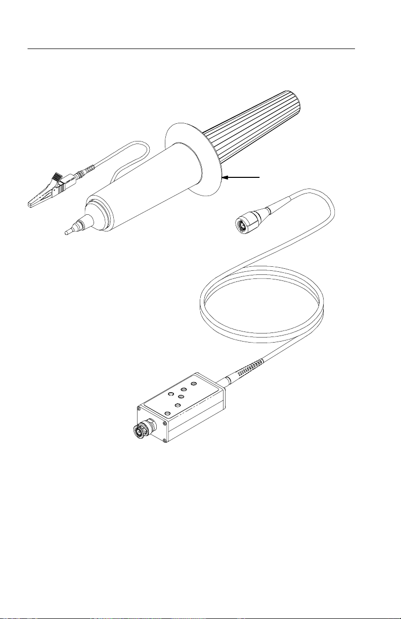
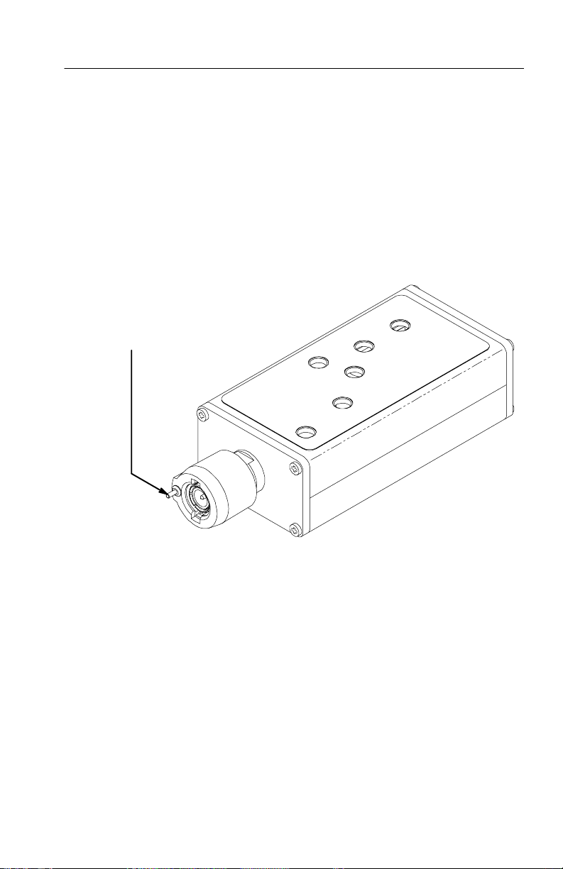
The P6015A consists of two major assemblies: the probe body and
the compensation box (see Figure 1--1).
H The probe body houses the probe tip, head, and ground lead. The
probe body is made of high-impact thermoplastic that provides
mechanical protection for the probe’s internal components and
electrical protection for the user.
H The compensation box connects a ground-referenced oscilloscope
or other grounded measuring device and has a cable that attaches
to the probe body. The compensation box contains an adjustment
network to optimize frequency response up to 75 MHz.
WARNING. To avoid shock, keep hands and fingers behind the guard
ring on the probe when the probe is connected to voltages.
P6015A Instruction Manual
1- 1
Page 16
Overview
Guard Ring
Figure 1- 1: The P6015A High-Voltage Probe
1- 2
P6015A Instruction Manual
Page 17
Readout Option
P6015A compensation boxes that feature the readout option have a
pin protruding from the BNC connector (Figure 1--2). Some models
of Tektronix oscilloscopes (11000 Series and Digital Storage
Oscilloscopes) read the code presented by this pin and automatically
scale the P6015A measurements by a factor of 1000 to compensate
for attenuation.
1000X Readout Pin
Overview
Figure 1- 2: Compensation Box with Readout Option
P6015A Instruction Manual
1- 3
Page 18

Overview
Standard Accessories
The P6015A comes with the following accessories:
H ground lead and plug-on clip
H hook-shaped probe tip
H banana-plug probe tip
H carrying case
H instruction manual
Options
The standard P6015A has a 10-ft cable without 1000X readout. The
following options are available:
H Option 1R: 10-ft cable and 1000X readout
H Option 25: 25-ft cable, no readout
H Option 2R: 25-ft cable and 1000X readout
1- 4
P6015A Instruction Manual
Page 19
Setup
Ground Lead
This section tells you how to assemble the P6015A modules as you
unpack them from the carrying case. Refer to Figure 1 --3 while
following these steps:
Handle
Inner Body
Figure 1- 3: Assembling the P6015A
P6015A Instruction Manual
Outer Body
1- 5
Page 20

Setup
1. Insert the end of the cable into the narrow end of the handle and
feed the BNC out the other side.
2. Connect the cable to the BNC on the probe head.
3. Screw the handle into the outer body.
4. Plug the crocodile ground clip onto the ground lead if it is not
already attached.
5. Read In Detail, beginning on page 1--7, before attempting to
make probe measurements.
1- 6
P6015A Instruction Manual
Page 21

In Detail
Before you make any oscilloscope measurement, observe all safety
precautions described in the user and service manuals for the
equipment you are working on. Some general rules about servicing
electrical equipment are worth repeating here.
H Observe the safety instruction symbols for the equipment you are
working on.
H Consult the service manual for the equipment you are working
on.
H Don’t operate or service an electrical device in an explosive
atmosphere.
H Avoid personal injury by never touching exposed connections or
components in the circuit-under-test when the power is on.
General Guidelines
To make high-voltage measurements with the P6015A probe, first
connect the BNC connector of the probe compensation box to the
measurement device (oscilloscope, digital voltmeter, etc.). Next,
connect the ground clip of the probe to a ground point of the circuit
under test. After you have made these connections, you are ready to
connect the probe tip to a high-voltage point.
Handheld Operation
The P6015A probe is designed for handheld use when used with the
straight or hook shaped probe tips. When using the straight tip, the
probe should be held by the plastic handle, behind the probe guard
ring, and the tip should be held against the high voltage test point.
The hook shaped tip can be used to hang the probe from a bus bar,
wire loop, or other test point.
P6015A Instruction Manual
1- 7
Page 22

In Detail
WARNING. When measuring high voltages, avoid contact with or
close proximity to any electrically conductive surface with your
body. Keep hands and fingers behind the guard ring on the probe.
WARNING. Make sure that the circuit is deenergized, and that any
stored energy is completely discharged before probe installation or
removal. Failure to discharge the circuit may cause serous or fatal
shock.
CAUTION. When mounting the probe into test fixtures, the duration
ratings in Table 1--1 on page 1--10 must be followed. Only clamp
onto the metal shield section of the probe when mounting the probe.
Intense electric fields are present when the probe is connected to a
high voltage source. Attaching a conductive or dielectric mount
beyond the metal shield may result in poor response characteristics
or probe damage.
1- 8
Readout
If your P6015A has the readout option and is being used with an
instrument having readout capability, the display automatically
corrects for the probe attenuation factor. (Refer to Overview on
page 1--1 for information about the P6015A readout option.)
If your instrument does not recognize the readout correction,
multiply your voltage measurements by 1000.
NOTE. Some oscilloscopes may misinterpret the 1000X attenuation
code. Contact your local Tektronix representative if you have
questions.
P6015A Instruction Manual
Page 23

In Detail
Probe Placement
CAUTION. Probe placement can be critical in some applicat ions.
To minimize Device-Under-Test circuit loading, the P6015A input
resistance is very large and input capacitance is very small. Small
changes in capacitance near the input resistor will affect the
accuracy of the measurement. These changes can result from placing
the probe tip near conductive surfaces. Changes in the input
capacitance will change the probe compensation, causing the leading
edge of pulses to overshoot or undershoot the true pulse amplitude.
The time constant will not be visible on shorter pulses where the
entire top of the measured waveform will appear to be the wrong
amplitude. Surfaces connected to the input signal will peak the
response, resulting in overshoot, while those that are static or
grounded will dampen the response, resulting in an undershoot.
To minimize the chance of changing the probe compensation, do not
allow the conductor, to which the probe is attached, to pass along the
side of the probe body. Keep the probe perpendicular to the attached
conductor or at the end of a dedicated test lead. If the test configuration does not allow this, minimize the error by readjusting the probe
compensation by connecting the probe to the calibration generator
that closely duplicates the physical configuration used in the actual
measurement.
P6015A Instruction Manual
1- 9
Page 24

In Detail
Maximum Input Voltage
Table 1--1 and the following paragraphs indicate conditions where
the maximum input of the P6015A is reduced.
Table 1- 1: Maximum Input Voltage
1,2,3
Max. On Time ≥30 Minutes <30 Minutes ≥15 Minutes <15 Minutes
Temperature
0to35 0to35 36 to 50 36 to 50
Range °C
4,5,6
V
RMS
V
DC
V
(DC+PK AC)
V
(Peak Pulse)
14 kV 20 kV 14 kV 20 kV
14 kV 20 kV 14 kV 20 kV
28 kV 40 kV 28 kV 40 kV
28 kV 40 kV 28 kV 40 kV
10% Duty Cycle
V
(Peak Pulse)
25 kV 36 kV 25 kV 36 kV
20% Duty Cycle
V
(Peak Pulse)
23 kV 33 kV 23 kV 33 kV
30% Duty Cycle
V
(Peak Pulse)
18 kV 28 kV 18 kV 28 kV
50% Duty Cycle
1
Voltage readings are based on a thermal time constant of 30 minutes with
no more than a 60_ internal temperature rise. Internal component heating
is not to exceed 4 W at less than 30 minutes or 2 W at greater than
30 minutes. If the 4 W limit is exceeded in less than 30 minutes, then a
cool-down period of up to 2.5 hours is required for any further probe use.
2
Voltage ratings are based on a thermal time constant of 30 minutes.
3
The maximum pulse duration must not exceed 100 ms (see the derating
chart in Figure 1- 5 on page 1- 13).
4
RMS=Root Mean Square=rms=The square root of the average of the sum of
Ꭹ
ᒑ
the squares of the instantaneous voltage in one cycle = .
5
RMS=(1/2 Peak V @ 25% DF)=(500 Vpk2)=250 V
6
RMS=[(V pk)2(DF)]
1/2
rms
(fxi)2ፒn
(DF = Duty Factor)
1- 10
P6015A Instruction Manual
Page 25

In Detail
The maximum input voltage of 20 kV (DC + peak AC) is derated at
frequencies above 460 kHz (See Figure 1--4 on page 1--12).
The maximum peak pulse of 40 kV (which must never exceed
20 kV
) is derated under the following conditions:
rms
H Duty cycles greater than 10% or durations longer than 100 ms
(Figure 1--5). Duty cycle is the ratio of pulse width to signal
period, expressed as a percentage.
H Altitudes higher than 8000 feet (2440 m). See tables 1--3 and
1--4.
H Relative humidity greater than 80% at 25° C, 70% at 35° C, or
30% at 50° C. See Tables 1--3 and 1--4.
H For voltages above Long Duration Line of Figure 1--5 on
page 1--13, the time e xposure is limited per Table 1-- 1 in any
2.5 hour period.
CAUTION. The ground lead is rated at 1 kV maximum. Make sure the
ground lead does not contact the probe tip or a high-voltage point on
the circuit under test.
NOTE. This probe is designed to take voltage measurements between
1.5 kV and 20 kV (DC + peak AC) and impulses up to 40 kV peak.
For taking voltage measurements below 1.5 kV, Tektronix makes a
variety of probes specifically for these applications.
P6015A Instruction Manual
1- 11
Page 26

In Detail
Maximum Displayed
Voltage-- 10 Foot Cable
Maximum
Input Voltage
Maximum Displayed
100 MHz10 MHz1MHz100 kMz10 kHz1kHz0.1
Voltage-- 25 Foot Cable
Maximum Input Voltage >1.5 kV
Sine Wave Frequency (100 kHz to 100 MHz)
>30 Minutes Duration
Maximum Input Voltage @
0.01
20 kV
10 kV
5kV
2kV
1kV
1.5 kV
Figure 1- 4: Maximum Input Voltage Derating (DC + Peak AC)
1- 12
P6015A Instruction Manual
Page 27

In Detail
40 kV
36 kV
33 kV
28 kV
20 kV
Maximum Voltage (peak)
10% Duty Cycle 100 ms on time
20%DutyCycle50msontime
30%DutyCycle40msontime
50%DutyCycle30msontime
100% Duty Cycle 100 ms on time
Figure 1- 5: Peak Pulse Derating
Probe Grounding
When making any measurement, use the probe ground connector to
form the basic two-terminal connection to the device under test.
CAUTION. The ground lead is rated at 1 kV maximum. Make sure the
ground lead does not contact the probe tip or a high-voltage point on
the circuit under test.
10 ms1ms
Duration
1sec100 ms
P6015A Instruction Manual
1- 13
Page 28

In Detail
NOTE. If you want to check the presence or absence of signals from
low-frequency equipment, and if the equipment is line-powered and
plugged into the same outlet system as the oscilloscope, then the
common three-wire ground system provides the signal ground return.
However, this indirect route adds inductance in the signal path,
which can produce ringing and noise on the displayed signal, and
therefore is not recommended.
Don’t assume that the ground in the circuit under test is the same as
the oscilloscope ground. Check the circuit ground by first attaching
the ground lead of the probe to a known earth ground, then touch the
probe tip to the point you think is ground. If there is any voltage
differential, then the point that the tip is connected to is not a valid
ground point. (Due to the 1000X attenuation of the P6015A, you
may have to increase the sensitivity of the oscilloscope in order to
see small voltage differentials.) Perform this check before you attach
the ground lead of the probe to a ground point on the circuit under
test. The oscilloscope ground should always be earth ground as long
as you are using the proper power cord and plug.
Ground Lead Inductance
When making any kind of absolute measurement, such as amplitude,
rise time or time delay measurements, use the shortest grounding
path possible.
1- 14
NOTE. Even with the shortest ground lead, probe capacitance and
ground lead inductance form a series-resonant circuit that has the
potential to ring. Such ringing oscillations depend on the high-frequency components of the transient you are measuring and will
distort the true waveform. The ability to see the ringing depends on
the oscilloscope bandwidth. The amount of displayed ringing can be
reduced by using the bandwidth limit function of the oscilloscope.
If you are going to be probing many different points in the same
circuit having signal frequencies less than 1 MHz, you can run a
ground wire from the circuit ground to the oscilloscope ground
terminal (if one is provided). Such a ground connection alleviates the
need to continually reconnect the probe ground lead.
P6015A Instruction Manual
Page 29

Probe Compensation
Short-Form Compensation Procedure
The short-form compensation procedure given in this section adjusts
for use of the probe on a different oscilloscope input or at a
drastically different temperature than that at which it was calibrated
(a difference greater than ±15_C). The adj ustments necessary under
these conditions are accessible through holes in the top cover of the
compensation box.
The long-form procedure is included in the Adjustments section of
Chapter 2. Use the long-form procedure when a part of the probe is
replaced, or when the probe has gone for a long time without
recompensation and cannot be compensated using the short-form
procedure. Should this become necessary, refer compe nsation to a
qualified service person.
The short-form procedure consists of three parts, which should be
performed in the order listed:
1. Adjust DC attenuation
In Detail
2. Adjust low-frequency compensation
3. Adjust transient response
Test Equipment Required. The test equipment listed in Table 1--2, or its
equivalent, is required for completion of this procedure. If equipment
is substituted, control settings or test equipment setup may need to
be altered. Any needed maintenance should be performed before
proceeding with compensation. Troubles that become apparent
during compensation should be corrected immediately.
P6015A Instruction Manual
1- 15
Page 30

In Detail
Table 1- 2: Test Equipment Required for Short-Form Adjustment
Item
Oscilloscope
Calibration
Generator
Minimum
Requirements
Input Impedance:1 MΩ
Sensitivity: 1 mV/div
Bandwidth: ≥100 MHz
Rise time: ≤10 ns
Repetition rate: 1 MHz
Recommended
Example Application
Tektronix 11402A
All adjustments
with 11A32 plugin, or Tektronix
TDS 460
Tektronix
PG 506A
1,2
All adjustments
Amplitude: ≥50 V
BNC Male-to-GR
Adapter
Tektronix
part number
All adjustments
017-0064-00
BNC 50 Ω
Termination
Tektronix
part number
011-0049-01
1
Oscilloscopes with less than 1mV/div sensitivity can be used while making
Transient
response
adjustment
most adjustments. However, because of the 1000X probe attenuation, the
system will not display sufficient defl ectio n for optimum adjustment of
transient response unless a calibration generator having higher amplitude
output is substituted.
2
Requires TM 500 or TM 5000 Series Power Module or equivalent.
1- 16
P6015A Instruction Manual
Page 31

In Detail
DC Attenuation
1. Connect the P6015A compensation box to the oscilloscope.
2. Connect a BNC male-to-GR adapter to the calibration generator
amplitude output. Connect the P6015A ground lead clip to the
outer fin of the GR connector.
WARNING. The calibration generator produces dangerous voltages
during these procedures. To avoid electrical shock, be careful not to
touch the GR center conductor or exposed portions of the probe tip
while the generator is on.
3. Insert the tip of the P6015A into the GR center conductor.
4. Set the calibration generator to standard amplitude output of
50 Volts. This setting on a PG 506A produces a 1 kHz square
wave.
5. Set the oscilloscope time base to display 500 s/div, and set the
vertical deflection to 10 mV/div (10 V/div when using the
readout option).
6. Center the waveform on the screen.
7. Adjust DC ATTEN (R9) for five divisions. Use the trailing portion
of the square wave if the leading corner is not flat.
P6015A Instruction Manual
1- 17
Page 32

In Detail
Low-Frequency Compensation
1. Set the calibration generator to high amplitude output, and set the
period to 1 ms. Set the pulse amplitude to display five divisions.
2. Set the oscilloscope time base to display 200 s/div.
3. Center the waveform on the screen.
4. Adjust LF COMP (C5) so that the leading corner of the square
wave is level with the trailing corner.
5. Adjust MID 1 (C1) to flatten the area 200 s from the leading
corner. Refer to Figure 1-- 6 to determine the zones affected by
this and the following adjustments.
200 s
Mid 1
100 s
Mid 2
50 s
Mid 3
Figure 1- 6: Zones Affected by Compensation Adjustments
1- 18
P6015A Instruction Manual
Page 33

In Detail
6. Adjust MID 2 (C2) to flatten the area 100 s from the leading
corner.
7. Adjust MID 3 (C4) to flatten the area 50 s from the leading
corner.
Some interaction exists between the LF COMP, MID 1, MID 2,and
MID 3 adjustments. Steps 4 through 7 may have to be repeated
several times to achieve optimum flatness of the square wave.
Transient Response
1. Set the calibration generator pulse amplitude to minimum.
2. Set the calibration generator output to a square wave with rise
time ≤10 ns. If you are using a PG 506A, do this by inserting a
50 Ω termination between the amplitude output and the BNC
male-to-GR adapter.
3. Set the oscilloscope time base to display 100 ns/div. Set the
oscilloscope vertical deflection to 1 mV/div (1 V/div when using
the readout option).
4. Set the calibration generator period to 1 s, and set the pulse
amplitude to display five divisions.
5. Center the waveform on the screen.
6. Adjust HF COMP (R6) for overall flatness of the front corner.
P6015A Instruction Manual
1- 19
Page 34

In Detail
Caring for the Probe
Follow these guidelines to prolong the life of your probe:
H Observe the time and temperature specifications for this product
shown in the Maximum Input Voltage Chart on page 1--4.
H Don’t connect a probe ground lead to elevated (“hot” ) circuitry.
The resultant damage is not covered by probe warranties.
H Don’t measure voltages in excess of the probe’s maximum
voltage rating.
H Don’t mount the probe into fixtures by its nonmetallic front end.
Mount the probe only by its metallic shield portion.
H Don’t attempt to remove the rubber cushioning ring from the
inner body assembly of the probe head.
H Don’t attempt to disassemble the inner body assembly.
H When you are not using the probe, place the probe and its
accessories in the case provided.
H Don’t use the probe to scrape through insulation, pry compo-
nents, or to move components.
1- 20
H When necessary, clean the probe with a damp cloth.
P6015A Instruction Manual
Page 35

Other Considerations
Component heating caused by changes in ambient temperature or
high voltage will cause a slight change in calibration accuracy.
With high-frequency signals, such as fast transients, ringing may
occur which will distort the actual waveform. This ringing is due to
resonance occurring between the capacitance of the probe and the
ground lead inductance.
Problems Encountered Using the Probe
If you experience problems making measurements with the probe,
consider the following remedies:
H Check low frequency compensation and adjust as necessary.
H If you have the probe connected to an oscilloscope, check the
front panel controls of the oscilloscope to verify that the signal is
displayed properly.
H Use a ground lead.
In Detail
H Don’t use ground leads that are too long (causing ringing).
H Because of probe characteristics, small differences in input
capacitance between oscilloscopes and scope channels can affect
the voltage measurement. The probe compensation should be
checked each time the probe is connecte d to a different input
channel or to a different oscilloscope.
P6015A Instruction Manual
1- 21
Page 36

In Detail
1- 22
P6015A Instruction Manual
Page 37

Specifications
Warranted Characteristics
This section lists the various warranted characteristics that describe
the P6015A High Voltage Probe. Included are warranted electrical
and environmental characteristics.
Warranted characteristics are described in terms of quantifiable
performance limits which are warranted.
The electrical characteristics listed in Table 1--3 apply under the
following conditions:
H The probe and instrument with which it is used must have been
calibrated at an ambient temperature of between +20 °Cand
+30 °C.
H The probe and instrument must be in an environment whose
limits are described in Table 1-3.
H The probe and instrument must have had a warm-up period of at
least 20 minutes before applying elevated voltages.
P6015A Instruction Manual
1- 23
Page 38

Specifications
Table 1- 3: Warranted Electrical Characteristics
Characteristic Information
Maximum input voltage
DC + peak AC
1
1.5 kV to 20 kV. See frequency derating curve in
Figure 1--4. (DC plus peak AC rating is limited to
temperatures below 35° C.)
Peak pulse 40 kVa(Never exceed 20 kV rms)
Duty cycle derating -- 100 ms maximum duration at 10%
maximum duty cycle. See duration and duty cycle
derating curve in Figure 1--5.
Altitude derating -- Peak pulse derated linearly from
40 kV at 8000 feet (2440 m) to 30 kV at 15,000 feet
(4570 m) altitude.
Relative Humidity (RH) derating -- Voltage derated with
increasing temperature and relative humidity (see
Figure 1--7).
Bandwidth (--3 dB) Test conditions: Test oscilloscope bandwidth must be
≥100 MHz, Z
10-ft cable
25-ft cable
Rise Time
10-ft cable
25-ft cable
2
75 MHz
25 MHz
≤4.67 ns (calculated from bandwidth)
≤14 ns (calculated from bandwidth)
DC attenuation 1000:1 ±3% (Excluding
oscilloscope error)
source
=25Ω
Test conditions: Oscilloscope input resistance
mustbe1MΩ ±2%
1
Characteristic not checked in manual
2
Tr(ns) = .35/BW (MHz)
1- 24
P6015A Instruction Manual
Page 39

Table 1- 4: Warranted Environmental Characteristics
Characteristic Information
Temperature
Nonoperating
Operating
DC + peak AC
-- 5 5 _Cto+75_C(--67_F to +167_F)
0_Cto+35_ C(+32_ Fto+95_F)
Specifications
Peak Pulse
Humidity
Nonoperating / Operating 95% relative humidity at +50 °C (+122 °F). See
Maximum altitude
Nonoperating 15,000 m (50,000 ft)
Operating 4,600 m (15,000 ft)
Vibration (random)
Nonoperating 3.48 g rms from 5 to 500 Hz. Ten minutes on each axis.
Operating 2.66 g rms from 5 to 500 Hz. Ten minutes on each axis.
Shock (nonoperating) 500 g, half sine, 0.5 ms duration, 18 shocks total in three
Time Limitations
Less than 70% of Rated
Input Voltage at 0--35_C
Greater than 70% of
Rated Input Voltage at
0--35_C
35--50_C
0_Cto+50_ C(+32_ F to +122_F)
(See Table 1--1 on page 1--10 and Time Limitations
Specification below)
Figure 1--7 for derating characteristics.
Peak pulse voltage derated from 40 kV at 8000 feet
(2440 m) to 30 kV at 15,000 feet (4570 m).
axis.
No time limit
30 minutes maximum
in any 2.5 hour period
15 minutes maximum
in any 2.5 hour period
P6015A Instruction Manual
1- 25
Page 40

Specifications
25 °C
35 °C
50 °C
0% 30% 70% 80%
40 kV
40 kV
40 kV
35 kV
Relative Humidity
Figure 1- 7: Humidity Derating Chart
100 M
10 M
1M
Phase Angle
100 k
Probe Impedance
10 k
1k
10
100 1 k 10 k 100 k 1 M 10 M 100 M
Frequency
35 kV
35 kV
25 kV
20 kV
95%
0°
-- 1 0 °
-- 2 0 °
-- 3 0 °
-- 4 0 °
-- 5 0 °
-- 6 0 °
-- 7 0 °
-- 8 0 °
-- 9 0 °
Figure 1- 8: Typical Input Impedance and Phase
1- 26
P6015A Instruction Manual
Page 41

Typical and Nominal Characteristics
This section lists the various typical and nominal characteristics that
describe the P6015A High Voltage Probe.
Nominal characteristics are determined by design and/or inspection.
Nominal characteristics do not have tolerance limits.
Typical characteristics are described in terms of typical or average
performance. Typical characteristics are not warrante d.
Table 1- 5: Typical Electrical Characteristics
Characteristic Information
Specifications
Input resistance
Input capacitance ≤3 pF when probe is properly LF compensated. See
LF compensation range 7pFto49pF
Aberrations 25% p-p for the first 200 ns on a 100 MHz oscilloscope
Temperature coefficient of DC
attenuation
Voltage coefficient of DC attenuation
Delay time 10 ft cable: 14.7 ns
1
Resistor temperature rose 60_Cat20kVrmsovera30minuteperiod.
100 MΩ ±2%. See Figure 1-- 8 for typical input
impedance curve.
Figure 1--8 for typical input impedance curve.
when used with 10 in (25.4 cm) ground lead.
<10% p-p typical after first 200 ns; ±5% after the first
400 ns.
0.006% per degree C
0.018% per kV
25 ft cable: 33.3 ns
1
P6015A Instruction Manual
1- 27
Page 42

Specifications
Table 1- 6: Nominal Mechanical Characteristics
Characteristic Information
Diameter (probe body) 8.9 cm (3.5 in) maximum
Length (probe body) 34.5 cm (13.6 in)
Length (cable)
10-ft cable 3.05 m (10 ft)
25-ft cable 7.62 m (25 ft)
Compensation box 2.5 × 4.1 × 8.3 cm (1 × 1.6 × 3.25 in)
Net weight (probe assembly)
10-ft cable 0.66 kg (1.47 lbs)
25-ft cable 0.75 kg (1.66 lbs)
Shipping weight (including
accessories)
10-ft cable 2.85 kg (6.27 lbs)
25-ft cable 2.93 kg (6.46 lbs)
1- 28
P6015A Instruction Manual
Page 43

WARNING
The following servicing instructions are for use only by
qualified personnel. To avoid injury, do not perform any
servicing other than that stated in the operating instructions
unless you are qualified to do so. Refer to all safety
summaries before performing any service.
Page 44

Page 45

Service Information
Page 46

Page 47

Performance Verification
The performance verification procedure verifies that the P6015A
performs as described in the Specifications section of Chapt er 1. This
procedure can also be used as an acceptance check. The procedure is
given in the next section, Adjustments.
The performance verification consists of the long-form compensation procedure with an additional step to check bandwidth and rise
time:
1. Check DC attenuation and adjust if necessary
2. Check low-frequency compensation and adjust if necessary
3. Check transient response and adjust if necessary
4. Check bandwidth and calculate rise time
P6015A Instruction Manual
2- 1
Page 48

Performance Verification
2- 2
P6015A Instruction Manual
Page 49

Adjustments
Recalibration ordinarily is necessary only if the P6015A is being
used on a different oscilloscope input or at a drastically different
temperature than that at which it was calibrated (a difference greater
than ±15_C). The adjustments necessary for recalibration under
these conditions are accessible through holes in the top cover of the
compensation box. The basic probe compensation procedure is given
in the In Detail section of Chapter 1 in this manual .
Limits, tolerances, and waveforms in this procedure are given as
adjustment guides. Refer to the Specifications section of this manual
for actual performance criteria.
Any needed maintenance should be performed before proceeding
with compensation. Troubles that become apparent during
compensation should be corrected immediately.
Test Equipment Required
The test equipment listed in Table 2--1 (or its equivalent) is required
for completion of this procedure. If equipment is substituted, control
settings or test equipment setup may need to be altered.
Preparation
Warm up the test equipment at least 20 minutes to stabilize it before
performing the checks and adjustments.
P6015A Instruction Manual
2- 3
Page 50

Adjustments
Table 2- 1: Test Equipment Required for Long-Form Adjustment
Item
Oscilloscope
Calibration
Generator
Minimum
Requirements
Input Impedance:1 MΩ
Sensitivity: 1 mV/div
Bandwidth: ≥100 MHz
Rise time: ≤10 ns
Repetition rate: 1 MHz
Recommended
Example Application
Tektronix 11402A
with 11A32 plug-
All checks and
adjustments
in, or Tektronix
TDS 460
Tektronix
PG 506A
1,2
All checks and
adjustments other
than bandwidth
Amplitude: ≥50 V
Leveled Sine
Wave Generator
BNC Male-to-GR
Adapter
Range: 50 kHz to 75 MHz
Amplitude: ≥5V
Tektronix SG 5032Bandwidth check
Tektronix
part number
All checks and
adjustments
017-0064-00
BNC 50 Ω
Termination
Tektronix
part number
011-0049-01
Transient
response check
and adjustment,
bandwidth check
1
Oscilloscopes with less than 1 mV/div sensitivity can be used while
making most checks and adjustments. However, because of the 1000X
probe attenuation, the system will not display sufficient deflection for
optimum adjustment of transient response unless a calibration generator
having higher amplitude output is substituted.
2
Requires TM 500 or TM 5000 Series Power Module or equivalent.
2- 4
P6015A Instruction Manual
Page 51

Long-Form Procedure
The long-form compensation procedure typically should be
necessary only under these conditions:
H the probe head or compensation box has been replaced
H the probe has come out of compensation because of aging effects
over a prolonged period
Access to adjustments in this procedure requires removal of the top
half of the compensation box (Figure 2--1). When reinstalling the
top, note that the edges are asymetrical and that the top will seat
securely only when it is correctly oriented. This ensures that the
adjustment holes are properly aligned with the circuit board.
Adjustments
Figure 2- 1: Access to Long-Form Adjustments
P6015A Instruction Manual
2- 5
Page 52

Adjustments
The long-form adjustment procedure consists of three parts which
must be performed in this order:
1. DC attenuation check and adjustment
2. Low-frequency compensation check and adjustment
3. Transient response check and adjustment
A fourth step, verification of bandwidth and rise time, is performed
only when this procedure is used as a performance verification
procedure.
DC Attenuation
1. Connect the P6015A compensation box to the oscilloscope.
2. Connect a BNC male-to-GR adapter to the calibration generator
WARNING. The calibration generator produces hazardous voltages
during these procedures. To avoid electrical shock, be careful not to
touch the GR center conductor or exposed portions of the probe tip
while the generator is on.
high/standard amplitude output. Connect the P6015A ground lead
to the outer fin of the GR connector.
2- 6
3. Insert the P6015A tip into the GR center conductor.
4. Set the calibration generator to standard amplitude output of
50 Volts. This setting on a PG 506A produces a 1 kHz square
wave.
5. Set the oscilloscope time base to display 500 s/div, and set the
vertical deflection to 10 mV/div (10 V/div when using the
readout option).
6. Center the waveform on the screen.
7. The waveform amplitude should be between 4.85 and 5.15
divisions. If necessary, adjust R9 for five divisions. Use the
trailing portion of the square wave if the leading corner is not
flat. See Figure 2--2 for the location of this and other adjustments.
P6015A Instruction Manual
Page 53

Adjustments
C7
R9
DC
ATTEN
R7
C4
MID 3
R6
HF
COMP
C5
LF
COMP
R5
C2
R4
C1
MID 1MID 2
R2
Figure 2- 2: Adjustment Locations
Low-Frequency Compensation
1. Set the calibration generator to high amplitude output, and set the
period to 1 ms. Set the pulse amplitude to display five divisions.
2. Set the oscilloscope time base to display 200 s/div.
3. Center the waveform on the screen.
4. The leading corner of the square wave should be level with the
trailing corner. If necessary, adjust C5.
5. The top of the waveform should be flat to within ±5% (±1.25 mi-
nor divisions). If necessary, perform steps 6 through 8.
P6015A Instruction Manual
2- 7
Page 54

Adjustments
200 s
R2,C1
100 s
R4,C2
50 s
R5,C4
Figure 2- 3: Periods Affected by Compensation Adjustments
2- 8
6. Adjust R2 and C1 to flatten the area 200 s from the leading
corner. Refer to Figure 2-- 3 to locate the zones affected by the
adjustments in this and the following steps.
NOTE. Figure 2--3 shows an idealized waveform. The displayed
waveform will include some ground lead ringing.
7. Adjust R4 and C2 to flatten the area 100 s from the leading
corner.
8. Adjust R5 and C4 to flatten the area 50 s from the leading
corner.
Adjustments R2, R4, R5, C1, C2, C4, and C5 interact. Steps 4 and 6
through 8 may have to be repeated several times to achieve optimum
flatness.
P6015A Instruction Manual
Page 55

Adjustments
Transient Response
1. Set the calibration generator pulse amplitude to minimum.
2. Set the calibration generator to output a square wave with rise
time ≤10 ns. If you are using a PG 506A, do this by inserting a
50 Ω termination between the high/standard amplitude output
and the BNC male-to-GR adapter.
3. Set the oscilloscope time base to display 100 ns/div. Set the
oscilloscope vertical deflection to 1 mV/div (1 V/div when using
the readout option).
4. Set the calibration generator period to 1 s, and set the pulse
amplitude to display five divisions.
5. Center the waveform on the screen.
6. The waveform should be flat overall, and the front corner should
be sharp without overshoot. If necessary, perform step s 7 and 8.
7. Adjust R6 for overall flatness of the front corner.
8. Adjust R7 and C7 for a sharp front corner without overshoot.
There is interaction between R6, R7, and C7. You may have to
repeat steps 7 and 8 to obtain optimum response.
P6015A Instruction Manual
2- 9
Page 56

Adjustments
Bandwidth and Rise Time Verification
The following check is part of the performance verification
procedure. You may omit it if you are performing the adjustment
procedure.
1. Substitute the sine wave generator for the calibration generator.
2. Set the oscilloscope vertical deflection to 1 mV/div (1 V/div
3. Set the generator frequency to 50 kHz, and set the amplitude to
4. Increase the generator frequency to:
when using the readout option), and set the time base to display
10 s/div.
display five divisions peak-to-peak.
H 75 MHz for a 10 ft. (3 m) cable.
H 25 MHz for a 25 ft. (7 m) cable.
while observing the oscilloscope display. Set the generator
frequency to the point of lowest amplitude at or below
75 MHz (10 ft. cable) or 25 MHz (25 ft. cable).
2- 10
5. The amplitude of the waveform should be at least 3.5 divisions
(0.707 of the amplitude in Step 3).
This procedure does not check rise time directly, but it can be
approximated by the ratio t
= 0.35 / bandwidth.
r
P6015A Instruction Manual
Page 57

Maintenance
The P6015A ordinarily requires very little maintenance except for
occasional cleaning. This section provides procedures for preventive
maintenance, corrective maintenance, and removal and replacement
of parts.
Preventive Maintenance
Preventive maintenance for the P6015A consists of cleaning and
visual inspection.
CAUTION. Do not attempt to remove the rubber cushioning ring from
the front of the probe. The ring is bonded to the probe body, and
removal of the ring may cause poor probe response or probe damage.
Cleaning
Accumulation of dirt on the probe body can provide a conduction
path that will result in electrical failure. The following procedures
describe how to clean the probe.
CAUTION. To prevent damage to the probe, do not expose it to sprays,
liquids, solvents or chemical cleaning agents. Avoid using chemicals
that contain benzine, benzene, toluene, xylene, acetone, or similar
solvents.
Probe Body. The part of the probe that is most vulnerable to arcing is
the space between the probe tip and the shield sleeve as shown in
Figure 2--4 on page 2--14. Inspect this area for dirt accumulation.
When necessary, clean the probe with a dry, lint-free cl oth or a
soft-bristle brush. If dirt remains, use a soft cloth or swab dampened
with a 75% isopropyl alcohol solution. A swab is useful for cleaning
narrow spaces on the probe, use only enough solution to dam pen the
P6015A Instruction Manual
2- 11
Page 58

Maintenance
swab or cloth. Do not use abrasive compounds on any part of the
probe.
Compensation Box. Cleaning the interior of the compensation box
should seldom be necessary. If cleaning is necessary, blow off any
accumulated dust with dry, low-velocity air stream. Remove any dirt
that remains with a soft brush. A cotton-tipped swab is useful for
cleaning in narrow spaces or for cleaning the circuit components.
Visual Inspection
Inspect the circuitry within the compensation box periodically for
loosely-seated or heat-damaged components. The corrective action
for most visible defects is obvious; however, particular care must be
taken if heat-damaged parts are found. Overheating usually indi cates
other problems in the probe or misuse; therefore, correct the cause of
overheating to prevent recurrence of the damage.
Troubleshooting and Repair
There are two repair options you should consider:
2- 12
H Tektronix Repair — You can ship your P6015A probe to us for
repair.
H Customer Repair — You can choose to repair the probe yourself.
If you decide to repair the probe yourself, order the replacement
part from your local Tektronix, Inc. service center or representative. See Replaceable Parts for part numbers.
Troubleshooting
Before using the probe, make sure it is properly compensated.
Compensate the probe to the vertical channel of the oscilloscope you
plan to use. Do not compensate it on one channel, then use it on
another. Also, check the vertical and horizontal system controls on
your oscilloscope to ensure that they are properly set to display the
signal from the device under test.
P6015A Instruction Manual
Page 59

Mechanical Disassembly and Assembly
This section contains mechanical procedures to aid in the replacement of parts within the probe head and compensation box
assemblies.
NOTE. Perform the long-form compensation procedure after
replacing a part.
Probe Head
The probe head consists of the parts shown in Figure 2--4. Refer to
that figure while performing the following steps to replace the inner
body or other parts.
Do Not Remove Rubber Ring
CAUTION. Do not attempt to remove the rubber cushioning ring at
the front of the inner probe body or the probe may be damaged and
its high voltage performance degraded. This ring is firmly attached
with an adhesive and is not designed to be removed.
Maintenance
Do Not Disassemble Inner Body
CAUTION. Do not attempt to disassemble the inner body assembly.
There are no user serviceable components in the inner body
assembly, and attempting to open the inner body assembly may result
in damage to its internal structure.
P6015A Instruction Manual
2- 13
Page 60

Maintenance
Handle
Shield Sleeve
Cushion Ring
Inner Body
Tip
2- 14
Outer Body
Figure 2- 4: Removal and Repl acement of Probe Head
P6015A Instruction Manual
Page 61

Maintenance
Removal.
1. Unscrew the probe tip.
2. Unscrew the plastic probe handle from the outer body, and slide
the handle back on the cable. Slide the plastic outer body off the
front of the assembly.
3. Disconnect the cable BNC from the assembly.
Replacement.
1. Insert the ground lead connector through the slot in the outer
body. Insert the inner body assembly into the outer body. You
may have to lift up and forward on the ground lead to allow the
assembly to pass.
2. Connect the cable to the probe head BNC.
3. Screw the handle in place.
4. Replace the tip.
P6015A Instruction Manual
2- 15
Page 62

Maintenance
Compensation Box
The compensation box assembly contains three parts that can be
replaced individually: the compensation box/circuit board assembly,
the cable, and the BNC that connects to the oscilloscope or other
instrument. Follow these procedures to replace either the cable or the
BNC, or to install them on a new compensation box. The procedures
are the same in each case.
Removal.
1. Remove the top half of the compensation box.
2. Unsolder the cable (or BNC) center conductor.
3. Unscrew the cable bushing (or BNC).
Replacement.
1. Screw the cable bushing (or BNC) into the end plate.
2. Form the conductor to the solder pad on the circuit board, then
3. Replace the top half of the compensation box. Note that the
solder the conductor in place.
edges are asymmetrical (as shown previously in Figure 2--1) and
that the top will seat securely only when it is correctly oriented.
This ensures that the adjustment holes are properly aligned with
the circuit board.
2- 16
P6015A Instruction Manual
Page 63

Replaceable Parts
This section contains a list of the components that are replaceable for
the P6015A. As described below, use this list to identify and order
replacement parts.
Parts Ordering Information
Replacement parts are available from or through your local
Tektronix, Inc. service center or representative.
Changes to Tektronix instruments are sometimes made to accommodate improved components as they become available and to give you
the benefit of the latest circuit improvements. Therefore, when
ordering parts, it is important to include the following information in
your order:
H Part number
H Probe type or model number, including option numbers
H Probe serial number
H Probe modification number, if applicable
The P6015A is serviced by module replacement. In some cases you
may exchange your module for a remanufactured module. These
modules cost significantly less than new modules and meet the same
factory specifications. For more information, contact you local
Tektronix, Inc. service center or representative.
If a part you order has been replaced with a different or improved
part, your local Tektronix service center or representative will
contact you concerning any change in the part number.
Change information, if any, is located at the rear of this manual.
P6015A Instruction Manual
2- 17
Page 64

Replaceable Parts
Using the Replaceable Parts List
The tabular information in the Replaceable Parts List is arranged for
quick retrieval. Understanding the structure and features of the list
will help you find all the information you need for ordering
replacement parts.
Item Names
In the Replaceable Parts List, an Item Name is separated from the
description by a colon (:). Because of space limitations, an Item
Name may sometimes appear as incomplete. For further Item Name
identification, U.S. Federal Cataloging Handbook H6-1 can be used
where possible.
Abbreviations
Abbreviations conform to American National Standards Institute
(ANSI) standard Y1.1
2- 18
P6015A Instruction Manual
Page 65

Replaceable Parts
7
6
11
4
3
5
8
9
10
2
1
Figure 2- 5: P6015A Exploded View
2- 19P6015A Instruction Manual
Page 66

Replaceable Parts
CLIP,ELECTRICAL:ALLIGATOR,2.5 L,W/PLUG & COVER
CONN,RF PLUG:BNC,;50 OHM,MALE,STR,
FEEDTHRU/FRONT PNL,1.555 L,0.285 L 0.375-- 32 THD,0.5L
22 AWG TAB,0.384 DIA MTG
STANDARD ACCESSORIES
BODY,PROBE:OUTER,FINISHED
--2 196-- 3363--00 1 LEAD ELECTRICAL:GROUND,STRD,18 AWG,10.0L
BODY,PROBE:OUTER,FINISHED
1
B019999 1
B010100
B020000
204-- 1106-- 01
--3 204-- 1106-- 00
--4 206-- 0116-- 00 1 TIP,PROBE:
--5 119--4636-- 02 1 PROBE,HV:75MHZ,10 FT;.COMP BOX ASSY
1
--6 367-- 0438--00 1 HANDLE,PROBE:6.0 L,NYLON,GRAY
--7 174-- 2579--00 1 CABLE ASSY,RF:50 OHM COAX,10FT L
--8 131-- 0602--00
STANDARD (10 FT CABLE- NO READOUT)
Name & Description
Qty
Dscont
Serial No. Effective
Part No.
Tektronix
Fig. &
Index No.
--1 344-- 0461--00 1 CLIP,ELEC:CROCODILE,82MM L,4MM
2--5--
CASE,CRYG,PROBE:
1
016-- 1147-- 00
MANUAL,TECH:INSTR,P6015A
1
B019999 1
B010100
070-- 8223--05
--9 344-- 0005--00
TIP,HOOK:PROBE
1
B020000
206-- 0463--00
--10 134-- 0016--00 B020000 1 PLUG,TIP:BANANA,10-- 32 INT THD END
--11 204-- 2202--02 1 BODY ASSY,PROBE; P6015A
2- 20 P6015A Instruction Manual
Page 67

Replaceable Parts
CLIP,ELECTRICAL:ALLIGATOR,2.5 L,W/PLUG & COVER
CONN,RCPT ASSY:ELEC WITH READOUT
STANDARD ACCESSORIES
BODY,PROBE:OUTER,FINISHED
--2 196-- 3363--00 1 LEAD ELECTRICAL:GROUND,STRD,18 AWG,10.0L
BODY,PROBE:OUTER,FINISHED
1
B019999 1
B010100
B020000
204-- 1106-- 01
--3 204-- 1106-- 00
1
--4 204-- 0116-- 01 1 BODY,VAR RES:PLASTIC
--5 119--4636-- 03 1 PROBE,HV:10 FT,W/READOUT;.COMP BOX ASSY
--6 367-- 0438--00 1 HANDLE,PROBE:6.0 L,NYLON,GRAY
--7 174-- 2579--00 1 CABLE ASSY,RF:50 OHM COAX,10FT L
--8 131-- 5320--00
OPTION 1R(10FT CABLE- W/READOUT)
Qty
Dscont
Serial No. Effective
Part No.
Tektronix
Fig. &
Index No. Name & Description
--1 344-- 0461--00 1 CLIP,ELEC:CROCODILE,82MM L,4MM
2--5--
CASE,CRYG,PROBE:
1
016-- 1147-- 00
MANUAL,TECH:INSTR,P6015A
1
B019999 1
B010100
070-- 8223--05
--9 344-- 0005--00
TIP,HOOK:PROBE
1
B020000
206-- 0463--00
--10 134-- 0016--00 B020000 1 PLUG,TIP:BANANA,10-- 32 INT THD END
--11 204-- 2202--02 1 BODY ASSY,PROBE; P6015A
2- 21P6015A Instruction Manual
Page 68

Replaceable Parts
CLIP,ELECTRICAL:ALLIGATOR,2.5 L,W/PLUG & COVER
CONN,RCPT ASSY:ELEC WITH READOUT
STANDARD ACCESSORIES
BODY,PROBE:OUTER,FINISHED
--2 196-- 3363--00 1 LEAD ELECTRICAL:GROUND,STRD,18 AWG,10.0L
BODY,PROBE:OUTER,FINISHED
1
B019999 1
B010100
B020000
204-- 1106-- 01
--3 204-- 1106-- 00
--4 206-- 0116-- 00 1 TIP,PROBE:
--5 119--4636-- 27 1 PROBE,HV:25 FT,W/READOUT;.COMP BOX ASSY
1
--6 367-- 0438--00 1 HANDLE,PROBE:6.0 L,NYLON,GRAY
--7 -- -------------- 1 CABLE ASSY,RF:31 OHM COAX,25FT L
--8 131-- 5320--00
OPTION 2R(25FT CABLE- W/READOUT)
Qty
Dscont
Serial No. Effective
Part No.
Tektronix
Fig. &
Index No. Name & Description
--1 344-- 0461--00 1 CLIP,ELEC:CROCODILE,82MM L,4MM
2--5--
CASE,CRYG,PROBE
1
016-- 1147-- 00
MANUAL,TECH:INSTR,P6015A
1
070-- 8223--05
TIP,HOOK:PROBE
B019999 1
B010100
--9 344-- 0005--00
1
B020000
206-- 0463--00
--10 134-- 0016--00 B020000 1 PLUG,TIP:BANANA,10-- 32 INT THD END
--11 204-- 2202--02 1 BODY ASSY,PROBE; P6015A
2- 22 P6015A Instruction Manual
Page 69

Replaceable Parts
CLIP,ELECTRICAL:ALLIGATOR,2.5 L,W/PLUG & COVER
CONN,RF PLUG:BNC,;50 OHM,MALE,STR,
FEEDTHRU/FRONT PNL,1.555 L,0.285 L 0.375-- 32 THD,0.5L
22 AWG TAB,0.384 DIA MTG
STANDARD ACCESSORIES
BODY,PROBE:OUTER,FINISHED
--2 196-- 3363--00 1 LEAD ELECTRICAL:GROUND,STRD,18 AWG,10.0L
BODY,PROBE:OUTER,FINISHED
1
B019999 1
B010100
B020000
204-- 1106-- 01
--3 204-- 1106-- 00
--4 206-- 0116-- 00 1 TIP,PROBE:
--5 119--4636-- 28 1 PROBE,HV:25 FT,W/NO READOUT;.COMP BOX ASSY
1
--6 367-- 0438--00 1 HANDLE,PROBE:6.0 L,NYLON,GRAY
--7 -- -------------- 1 CABLE ASSY,RF:31 OHM COAX,25 FT L
--8 131-- 0602--00
OPTION 25 (25FT CABLE- NO READOUT)
Qty
Dscont
Serial No. Effective
Part No.
Tektronix
Fig. &
Index No. Name & Description
--1 344-- 0461--00 1 CLIP,ELEC:CROCODILE,82MM L,4MM
2--5--
CASE,CRYG,PROBE:
1
016-- 1147-- 00
MANUAL,TECH:INSTR,P6015A
1
B019999 1
B010100
070-- 8223--05
--9 344-- 0005--00
TIP,HOOK:PROBE
1
B020000
206-- 0463--00
--10 134-- 0016--00 B020000 1 PLUG,TIP:BANANA,10-- 32 INT THD END
--11 204-- 2202--02 1 BODY ASSY,PROBE; P6015A
2- 23P6015A Instruction Manual
Page 70

Replaceable Parts
2- 24 P6015A Instruction Manual
Page 71

Index
Page 72

Page 73

Index
A
accessories, standard, 1-- 4
adjustments
access, 2--5
DC attenuation, 2--6
long-form procedure, 2--5
low-frequency compensation,
2--7
preparation, 2--3
test equipment required, 2--3, 2--4
transient response, 2--9
C
calibration, period, 2--3
characteristics, 1-- 21, 1-- 25
aberrations, 1--25
altitude, 1-- 23
bandwidth, 1-- 22
calibration temperature, 1--21
DC attenuation, 1--22
delay time, 1--25
general, 1--1
humidity, 1-- 23
input capacitance, 1--25
input impedance, 1--24
input resistance, 1--25
low-frequency compensation,
1--25
maximum input voltage, 1--9,
1--22
frequency derating curve, 1--10
peak pulse derating, 1--11
mechanical, 1-- 26
operations, 1-- 21
rise time, 1--22
shock, 1--23
temperature, 1--23, 1-- 25
vibrations, 1-- 23
voltage, 1-- 25
warm-up period, 1--21
compensation box
assembly, 2--16
cleaning, 2-- 12
description, 1-- 1
Contacting Tektronix, ix
crocodile clip, 1--6
cushioning ring, 2--11
D
distortion, high-frequency, 1--19
G
general information, 1--1
ground lead
distortion, 1-- 19
inductance, 1-- 12
lead length, 1--12
ringing, 1--19, 2--8
safety, 1--9, 1-- 11
M
maintenance
assembly, 2--13
cleaning, 2-- 11
general, 2--11
probe care, 1--18
probe cleaning, 1--18
solvents, 1--18
visual inspection, 2-- 12
P6015A Instruction Manual
Index- 1
Page 74

Index
O
operation, guidelines, 1--7
options, 1--4
readout, 1--3, 1--8
P
performance verification, general,
2--1
Phone number, Tektronix, ix
probe
assembly, 1--5, 2-- 13, 2-- 14, 2-- 15
body, 1-- 1
cleaning, 2-- 11
probe compensation, 1--13
long-form, 1--13
short-form, 1--13
DC attenuation, 1--15
low-frequency, 1--16
transient response, 1--17
test equipment required, 1--13
probe grounding, 1--11
inductance, 1-- 12
power cord, 1--12
ringing, 1--12
voltage differential, 1--12
problems, 1-- 19
front-panel controls, 1--19
grounding, 1--19
input capacitance, 1--19
low frequency compensation,
1--19
Product support, contact informa-
tion, ix
R
repair, 2-- 12
replacement parts
abbreviations, 2-- 18
general, 2--17
item names, 2--18
ordering, 2--17
probe, 20
ringing
ground lead, 1--19
power cord, 1--12
S
Service support, contact informa-
tion, ix
solvents, 2--11
specifications. See characteristics
T
Tektronix, contacting, ix
temperature, considerations, 1--19
troubleshooting, general, 2--12
V
verification
bandwidth, 2-- 10
rise time, 2--10
Index- 2
P6015A Instruction Manual
 Loading...