

Page 1

x
P5200A Series
High Voltage Differential Probes
ZZZ
Instruction Manual
*P077053602*
077-0536-02
Page 2

Page 3

xx
P5200A Series
High Voltage Differential Probes
ZZZ
Instruction Manual
Revision B
www.tektronix.com
077-0536-02
Page 4

Copyright © Tektronix. All rights reserved. Licensed software products are owned by Tektronix or its subsidiaries or suppliers, and are
protected by na
tional copyright laws and international treaty provisions.
Tektronix pro
previously published material. Specifications and price change privileges reserved.
TEKTRONIX and TEK are registered trademarks of Tektronix, Inc.
ducts are covered by U.S. and foreign patents, issued and pending. Information in this publication supersedes that in all
Contacting Tektronix
Tektronix, Inc.
14150 SW Karl Braun Drive
P.O. Box 500
Beaverton, OR 97077
USA
For product information, sales, service, and technical support:
In North America, call 1-800-833-9200.
Worldwide, visit www.tek.com to find contacts in your area.
Page 5

Warranty
Tektronix warrants that this product will be free from defects in materials and workmanship for a period of one (1) year from the date of
shipment. If any such product proves defective during this warranty period, Tektronix, at its option, either will repair the defective
product without charge for parts and labor, or will provide a replacement in exchange for the defective product. Parts, modules and
replacement products used by Tektronix for warranty work may be new or reconditioned to like new performance. All replaced
parts, modules and products become the property of Tektronix.
In order to obtain s ervice under this warranty, Customer must notify Tektronix of the defect before the expiration of the warranty period
and make suitable arrangements for the performance of service. Customer shall be responsible for packaging and shipping the
defective product to the service center designated by Tektronix, with shipping charges prepaid. Tektronix shall pay for the return of the
product to Customer if the shipment is to a location within the country in which the Tektronix service center is located. Customer shall
be responsible for paying a ll shipping charges, duties, taxes, and any other charges for products returned to any other locations.
This warranty shall not apply to any defect, failure or damage caused by improper use or improper or inadequate maintenance and
care. Tektronix shall not be obligated to furnish service under this warranty a) to repair damage resulting from attempts by personnel
other than Tektronix representatives to install, repair or service the product; b) to repair damage resulting from improper use or
connection to incompatible equipment; c) to repair any damage or malfunction caused by the use of non-Tektronix supplies; or
d) to service a product that has been modified or integrated with other products when the effect of such modification or integration
increases the time or difficulty of servicing the product.
THIS WARRANTY IS GIVEN BY TEKTR ON IX WITH RESPEC T TO THE PRODUCT IN LIEU OF ANY OTHER WARRANTIES,
EXPRESS OR IMPLIED. TEKTRONIX AND ITS VENDORS DISCLAIM ANY IMPLIED WARRANTIES OF MERCHANTABILITY OR
FITNESS FOR A PARTICULAR PURPOSE. TEKTRONIX' RESPONSIBILITY TO REPAIR OR REPLACE DEFECTIVE PRODUCTS
IS THE S O L E AND EXCLUSIVE REMEDY PROVIDED TO THE CUSTOMER FO R BREACH OF THIS WARRANTY. TEKTRONIX
AND ITS V ENDORS WILL NOT BE LIABLE FOR ANY INDIRECT, SPECIAL, INCIDENTAL, OR CONSEQUENTIAL DAMAGES
IRRESPECTIVE OF WHETHER TEKTRONIX OR THE VENDOR HAS ADVANCE NOTICE OF THE POSSIBILITY OF SUCH
DAMAGES.
[W2 – 15AUG04]
Page 6

Page 7

Table of Contents
General safety summary . .. .... . ... . . ... . ... . . ... . ... . . ... . ... . . ... . ... . . ... . ... . . ... . ... . . ... . ... . . ... . ... . . ... . ... . . ... . ... . . ... . ... iii
Compliance I
Preface ................................................................................................................................. ix
Probe Operating Information .......................................................................................................... 1
Accessori
Options ................................................................................................................................ 23
Operatin
Specifications .........................................................................................................................28
Performance Verification ............................................................................................................. 36
Adjustments........................................................................................................................... 41
Troubleshooting. . . ... . ... . . ... . ... . . ... . ... . . ... . ... . . ... . ... . . ... . ... . . ... . ... . . ... . ... . . ... . ... . ... . . ... . ... . . ... . ... . . ... . ......... 55
ex
Ind
nformation ............................................................................................................... v
EMC Compliance................................................................................................................. v
Safety Compliance ............................................................................................................... vi
Environmen
Connectin
Probe Controls ...................................................................................................................5
Functional Check. . ... . . ... . ... . . ... . ... . . ... . . ... . ... . . ... . ... . . ... . ... . . ... . . ... . ... . . ... . ... . . ... . ... . . ... . .... . ... . . ... . ... . . .7
Connecting to the Circuit. . ... . ... . . ... . ... . ... . ... . . ... . ... . ... . . ... . ... . ... . . ... . ... . ... . ... . . ... . ... . . .. . . ... . ... . ... . . ... . ... . 8
g Basics ..................................................................................................................... 24
Operating Characteristics and Probing Techniques . ... . . ... . ... . . ... . . ... . ... . . ... . . ... . ... . . ... . .... . ... . . ... . ... . . ... . ... . . 24
Warrant
Typical Specifications ........................................................................................................... 29
Nominal Specifi cations.......................................................................................................... 31
Perfor
Required Equipment . . . ... . ... . . ... . ... . . ... . ... . . ... . ... . . ... . ... . . ... . ... . . ... . ... . . ... . ... . . ... . ... . . ... . . ... . ... . . ... . ... . . . 36
Test Pr
Equipment Required . . ... . . ... . ... . . ... . . ... . ... . . ... . ... . . ... . ... . . ... . ... . . ... . ... . . ... . ... . . ... . . ... . ... . . ... . ... . . ... . ... . . 43
Adjus
Host Instrument Firmware ...................................................................................................... 55
Erro
Cleaning . . ... . . ... . ... . . ... . ... . . ... . ... . ... . . ... . ... . . ... . ... . . ... . ... . . ... . ... . . ... . ... . ... . . ... . ... . . ... . ... . . ... . ... . . ... . ... 56
Service........................................................................................................................... 56
tal Considerations................................................................................................. viii
g to the Instrument.................................................................................................... 2
es ............................................................................................................................ 8
ed Specifications ....................................................................................................... 28
mance Graphs ... . . ... . . ... . . ... . ... . . ... . .... . ... . . ... . . ... . .... . ... . . ... . ... . . ... . . ... . . ... . ... . . ... . . ... . ... . . ... . . ... . 32
ocedures . ... . . ... . ... . . ... . . ... . ... . . ... . ... . . ... . .... . ... . . ... . ... . . ... . . ... . ... . . ... . .... . ... . . ... . ... . . ... . ... . . ... . .. 37
tment Procedures . ... . . ... . .... . ... . . ... . .... . ... . . ... . . ... . ... . . ... . ... . . ... . . ... . ... . . ... . . ... . .... . ... . . ... . ... . . ... . .. 44
r Conditions . . ... . . ... . ... . . ... . ... . . ... . ... . . ... . ... . . ... . ... . . ... . ... . . ... . ... . . ... . ... . . ... . ... . . .. . . ... . ... . . ... . ... . . ... 55
Table of Content
s
P5200A Series High Voltage Differential Probes Instruction Manual i
Page 8

Table of C ontent
s
ii P5200A Series High Voltage Differential Probes Instruction Manual
Page 9

General safety s
ummary
General safet
Review the following safety precautions to avoid injury and prevent damage to this product or any products connected to it.
To avoid potential hazards, use this product only as specified.
Only qualified personnel should perform service procedures.
While using this product, you may need to access other parts of a larger system. Read the safety sections of the other
component manuals for warnings and cautions related to operating the system.
To avoid fire or personal injury
Use proper power cord. Use only the power cord specified for this product and certified for the country of use.
Connect and disconnect properly. Do not connect or disconnect probes or test leads while they are connected
to a voltag
Connect a
probe to the circuit under test. Connect the probe reference lead to the circuit under test before connecting the probe
input. Disconnect the probe input and the probe reference lead from the circuit under test before disconnecting the probe
from the m
Ground t
To avoid electric shock, the grounding conductor must be connected to earth ground. Before making connections to the input
or output terminals of the product, ensure that the product is properly grounded.
e source.
nd disconnect properly.
easurement instrument.
he product.
y summary
Connect the probe output to the measurement instrument before connecting the
This product is indirectly grounded through the grounding conductor of the mainframe power cord.
Observe all terminal ratings. To avoid fire or shock hazard, observe all ratings and markings on the product. Consult the
t manual for further ratings information before making connections to the product.
produc
Do not a
Power d
must remain accessible to the user at all times.
pply a potential to any terminal, including the common terminal, that exceeds the maximum rating of that terminal.
isconnect.
The power cord disconnects the product from the power source. Do not block the power cord; it
Do not operate without covers. Do not operate this product with covers or panels removed.
Do not operate with suspected failures. If you suspect that there is damage to this product, have it inspected by
qualified service personnel.
Avoid e xposed circuitry. Do not touch exposed connections and components when power is present.
Use proper AC adapter. Use only the AC adapter specified for this product.
Do not operate in wet/damp conditions.
Do not operate in an explosive atmosphere.
Keep product surfaces clean and dry.
P5200A Series High Voltage Differential Probes Instruction Manual iii
Page 10
General safety s
Termsinthismanual
These terms may appear in this manual:
WARNING. Warning statements identify conditions or practices that could result in injury or loss of life.
CAUTION. Caution statements identify conditions or practices that could result in damage to this product or other property.
Symbols and terms on the product
These terms may appear on the product:
DANGER indicates an injury hazard immediately accessible as you read the marking.
WARNING indicates an injury hazard not immediately accessible as you read the marking.
CAUTION indicates a hazard to property including the product.
The following symbol(s) may appear on the product:
ummary
iv P5200A Series High Voltage Differential Probes Instruction Manual
Page 11

Compliance Info
rmation
Compliance In
This section lists the EMC (electromagnetic compliance), safety, and environmental standards with which the instrument
complies.
EMC Compliance
EC Declaration of Conformity – EMC (Applies Only to th e P5200A Probe)
Meets intent of Directive 2004/108/EC for Electromagnetic Com patibility. Compliance was demonstrated to the following
specifications as listed in the Official Journal of the European Communities:
EN 61326-1:2006, EN 61326-2-1:2006. EMC requirements for electrical equipment for measurement, control, and
laboratory use.
CISPR 11:2003. Radiated and conducted emissions, Group 1, Class A
IEC 61000-4-2:2001. Electrostatic discharge immunity
IEC 61000-4-3:2002. RF electromagnetic field immunity
IEC 61000-4-4:2004. Electrical fast transient/burst immunity
IEC 61000-4-5:2001. Power line surge immunity
IEC 61000-4-6:2003. Conducted RF immunity
IEC 61000
123
-4-11:2004. Voltage dips and interruptions immunity
formation
4
EN 61000-3-2:2006. AC power line harmonic emissions
EN 61000-3-3:1995. Voltage changes, fluctuations, and flicker
European contact.
Tektronix UK, Ltd.
Western Peninsula
Western Road
Bracknell, RG12 1RF
United Kingdom
1
This product is intended for use in nonresidential areas only. Use in residential areas may cause electromagnetic interference.
2
Emissions which exceed the levels required by this standard may occur whe
3
To ensure compliance with the EMC standards listed here, high quality shielded interface cables should be used.
4
Performance Criterion C applied at the 70%/25 cycle Voltage-Dip and the 0%/250 cycle Voltage-Interruption test levels
(IEC 61000-4-11).
n this equipment is connected to a test object.
Australia / New Ze aland Declaration of Conformity – EMC
Complies with the EMC provision of the Radiocommunications Act per the following standard, in accordance with ACMA:
CISPR 11:2003. Radiated and Conducted Emissions, Group 1, Class A, in accordance with EN 61326-1:2006 and
EN 61326-2-1:2006.
P5200A Series High Voltage Differential Probes Instruction Manual v
Page 12

Compliance Info
rmation
Safety Compliance
Equipment Type
Differential Voltage Probe
EC Declarati
Compliance was demonstrated to the following specification as listed in the Official Journal of the European Communities:
Low Voltage Directive 2006/95/EC.
EN 61010-031/A1:2008. Safety requirements for electrical equipment for measurement, control and laboratory use - Part
031: S afety requirements for handheld probe assemblies for electrical measurement and test.
on of Conformity – Low Voltage
Canadian Certification
CAN/CSA-C22.2 No. 61010-031-07/A1:2010, 1st Edition. Safety requirements for handheld probe assemblies for electrical
measurem
ent and test.
Additional Compliances
IEC 61010-031/A1:2008. Safety requirements for electrical equipment for measurement, control and laboratory use - Part
031: S afety requirements for handheld probe assemblies for electrical measurement and test.
Pollution Degree Description
A measure of the contaminants that could occur in the environment around and within a product. Typically the internal
onment inside a product is considered to be the same as the external. Products should be used only in the environment
envir
for which they are rated.
Pollution Degree 1. No pollution or only dry, nonconductive pollution occurs. Products in this category are generally
encapsulated, hermetically sealed, or located in clean rooms.
Pollution Degree 2. Normally only dry, nonconductive pollution occurs. Occasionally a temporary conductivity that is
ed by condensation must be expected. This location is a typical office/home environment. Temporary condensation
caus
occurs only when the product is out of service.
Pollution Degree 3. Conductive pollution, or dry, nonconductive pollution that becomes conductive due to condensation.
These are sheltered locations where neither temperature nor humidity is controlled. The area is protected from direct
shine, rain, or direct wind.
sun
lution Degree 4. Pollution that generates persistent conductivity through conductive dust, rain, or snow. Typical
Pol
outdoor locations.
Pollution Degree
Pollution Degree 2 (as defined in IEC 61010-1). Note: Rated for indoor use only.
vi P5200A Series High Voltage Differential Probes Instruction Manual
Page 13

Compliance Info
Installation & Measurement (Overvoltage) Category Descriptio ns
Terminals on this product may have different installation or measurement (overvoltage) category designations. The
installation and measurement categories are:
Measurement Category IV. For measurements performed at the source of low-voltage installation.
Measurement Category III. For measurements performed in the building installation.
Measurement Category II. For measurements performed on circuits directly connected to the low-voltage installation.
Measurement Category I. For measurements performed on circuits not directly connected to MAINS.
Overvoltage Category (AC Adapter)
rmation
Overvolta
ge Category II (as defined in IEC 61010-1)
P5200A Series High Voltage Differential Probes Instruction Manual vii
Page 14

Compliance Info
rmation
Environmental Considerations
This section provides information about the environmental impact of the product.
Product End-of-Life Handling
Observe the following guidelines when recycling an instrument or component:
Equipment recycling. Production of this equipment required the extraction and use of natural resources. The equipment
may contain substances that could be harmful to the environment or human health if improperly handled at the product’s
end of life. To avoid release of such substances into the environment and to reduce the use of natural resources, we
encourage you to recycle this product in an appropriate system that will ensure that most of the materials are reused
or recycled appropriately.
This symbol indicates that this product complies with the applicable European Union requirements according
to Directives 2002/96/EC and 2006/66/EC on waste electrical and electronic equipment (WEEE) and
batteries. For information about recycling options, check the Support/Service section of the Tektronix Web
site (www.tek.com).
Restriction of Hazardous Substances
This product has been classified as Monitoring and Control equipment, and is outside the scope of the 2002/95/EC RoHS
ve.
Directi
viii P5200A Series High Voltage Differential Probes Instruction Manual
Page 15

Preface
This document provides operating information and specifications for the Tektronix P5200A Series high voltage differential
probes. The probes share similar functions, properties, and operating procedures, and are discussed in the firstpartofthe
manual. The specifications and performance verification procedures for the probes follow.
WARNING. Only use the accessories that are designed for your probe and that are rated at or above the voltages you are
measuring. (See Table i on page x.) (See Table ii on page xiii.)
Name Bandwidth Attenuation Oscilloscope interface
P5200A 50 MHz
P5202A 100 MHz
P5205A 100 MHz
P5210A 50 MHz
Preface
50X/500X BNC
20X/200X TekProbe BNC-Level 2
50X/500X TekProbe BNC-Level 2
100X/1000X TekProbe BNC-Level 2
P5200A Series High Voltage Differential Probes Instruction Manual ix
Page 16

Preface
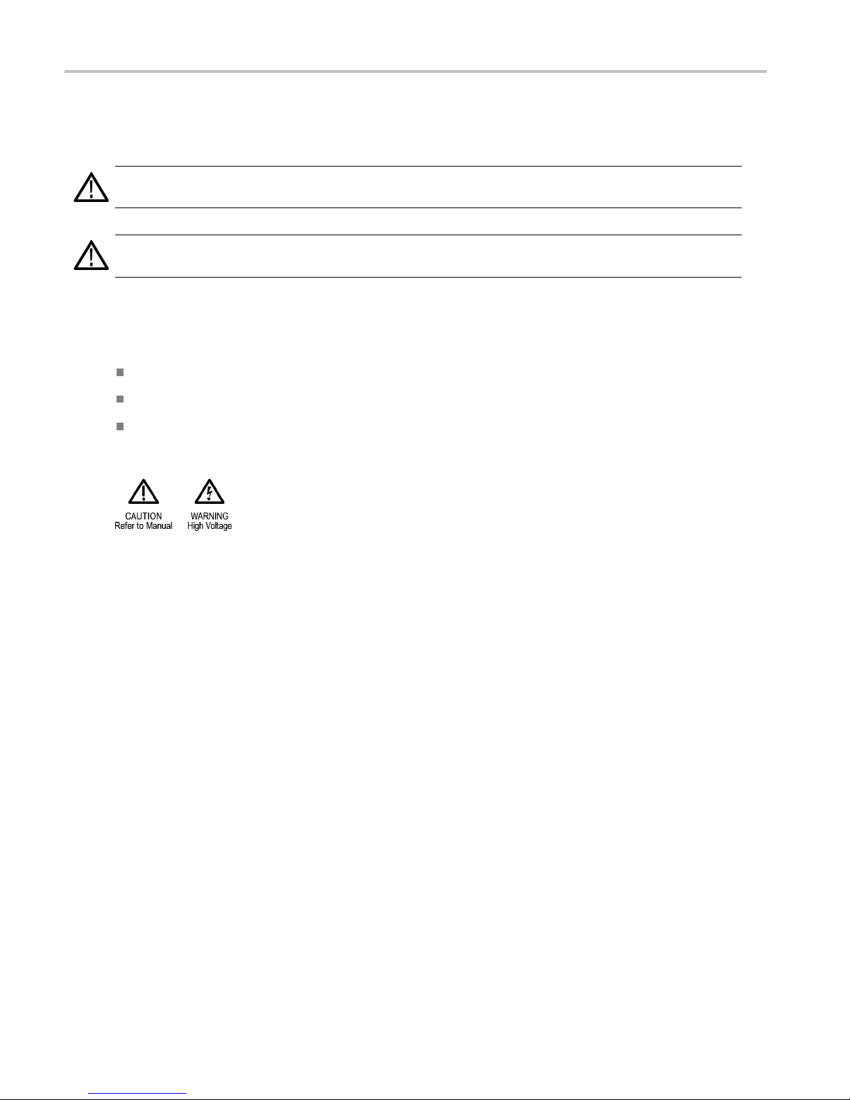
Figure i: P5200A High Voltage Differential Probe with accessories
Table i: P5200A, P5202A & P5205A probe standard accessories derating table
Combined probe and accessory common-mode voltage
put vo ltage-to-earth ratings
and in
ssory
Acce
Extender leads
Hook clips (AC280-FL) 450 V CAT I
Pincer clips (AC283-FL) 450 V CAT I
lligator clips (AC285-FL)
A
1
The P5200A, P5202A & P5205A standard accessories can also be used with the P5210A probe, but only at the reduced voltage levels listed here.
2A
P520
VCATI
450
300 V CAT II
300 V CAT II
0VCATII
30
50VCATI
4
300 V CAT II
0A & P5205A
P520
0VCATII
100
600 V CAT III
1000 V CAT II
600 V CAT III
1000 V CAT II
0 V CAT III
60
000VCATII
1
600 V CAT III
P521
230
1000 V C AT III
1000 V CAT I
1000 V C AT III
1000 V CAT I
10
1
1000 V C AT III
1
0A
0VCATI
00 V CAT III
000VCATI
x P5200A Series High Voltage Differential Probes Instruction Manual
Page 17
Preface
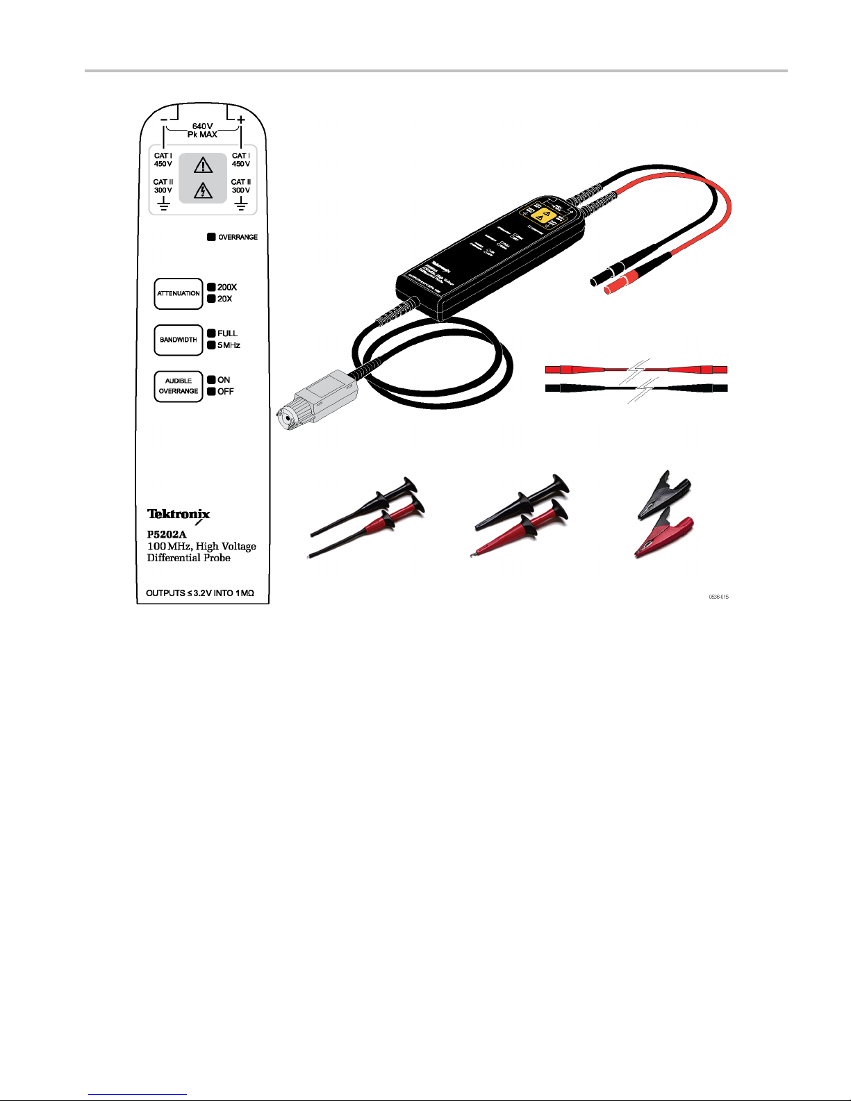
Figure ii: P5202A High Voltage Differential Probe with accessories
P5200A Series High Voltage Differential Probes Instruction Manual xi
Page 18
Preface
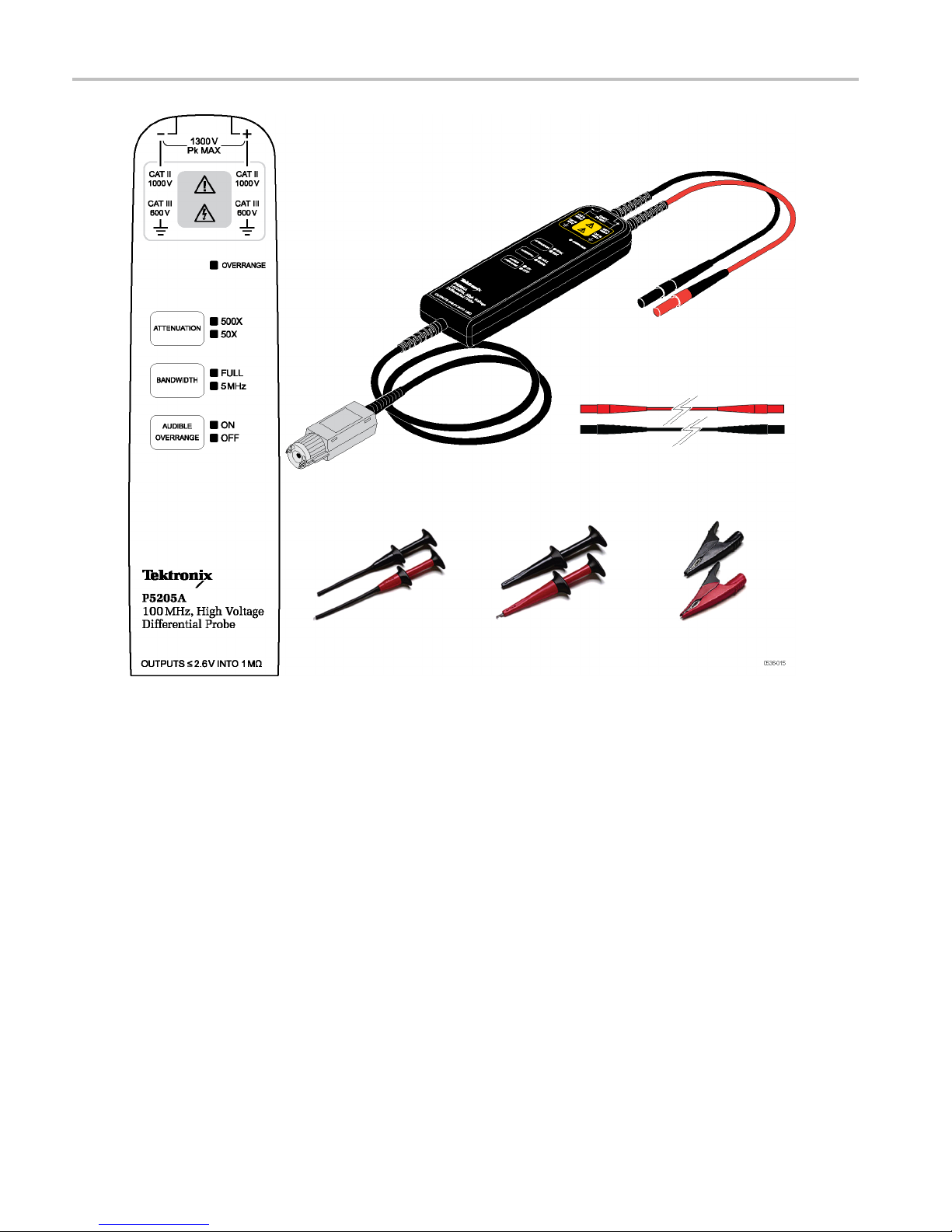
Figure iii: P5205A High Voltage Differential Probe with accessories
xii P5200A Series High Voltage Differential Probes Instruction Manual
Page 19
Preface
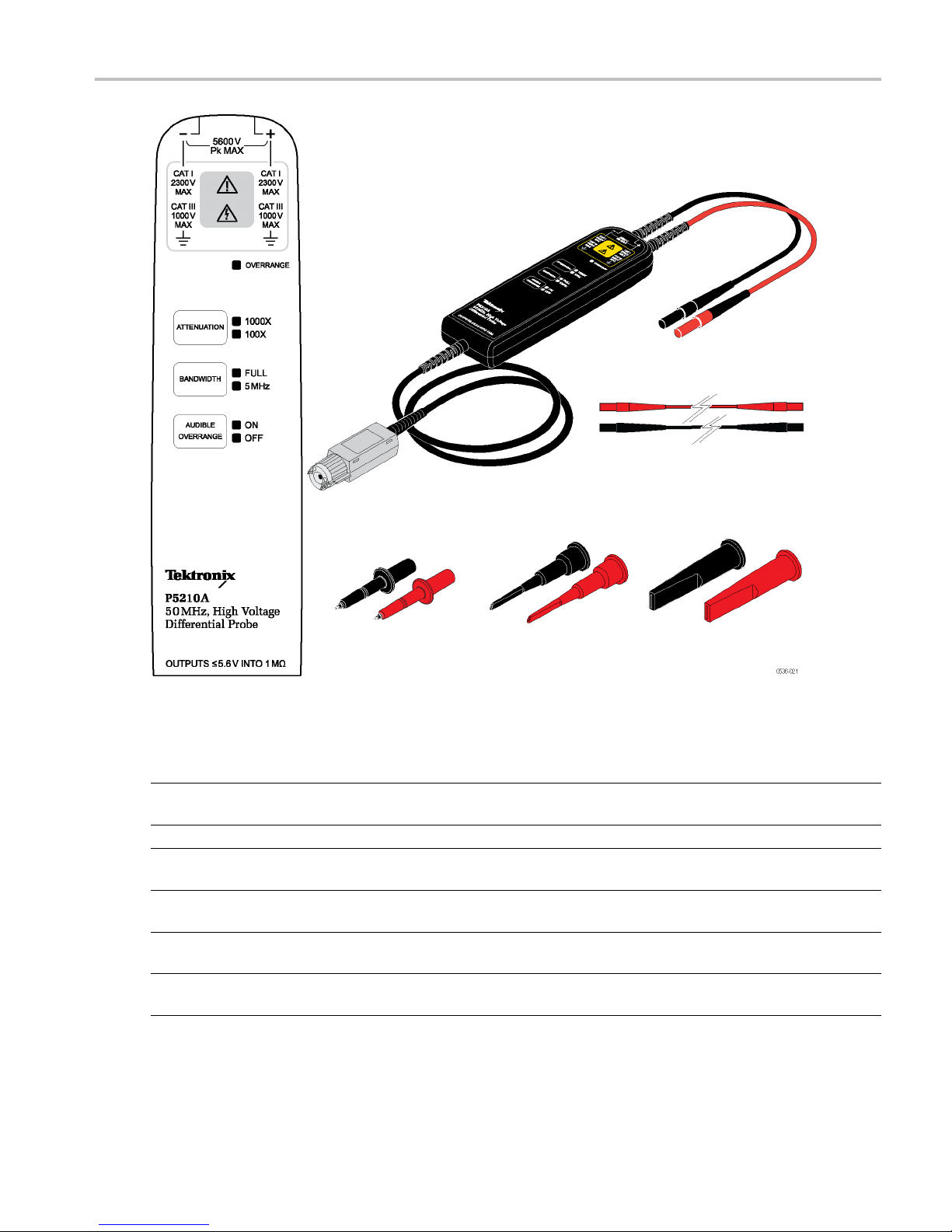
Figure iv: P5210A High Voltage Differential Probe with accessories
Table ii: P5210A probe standard accessories derating table
Combined probe and accessory common-mode voltage
put voltage-to-earth ratings
and in
ssory
Acce
Extender leads
P520
450
300 V CAT II
Test probe (TATP) 450 V CAT I
300 V CAT II
Small hook tip (TASH) 450 V CAT I
30
arge hook tip (TALH)
L
4
300 V CAT II
1
The P5210A standard accessories can be used with these probes at the reduced voltage levels listed in this table.
1
2A
VCATI
0VCATII
50VCATI
0A & P5205A
P520
0VCATII
100
600 V CAT II
1000 V CAT II
600 V CAT II
1000 V CAT II
0VCATII
60
000VCATII
1
600 V CAT II
1
P521
0VCATI
230
0A
1000 V CAT III
1000 V CAT I
1000 V CAT II
2300 V CAT I
00 V CAT II
10
300 V CAT I
2
1000 V CAT II
P5200A Series High Voltage Differential Probes Instruction Manual xiii
Page 20
Probe Operating
Information
Probe Operati
The P5200A Series probes share many common features, including connections to the circuit, compensation box buttons,
and operating basics. The probes connect to the host oscilloscope through one of two probe-to-oscilloscope interfaces:
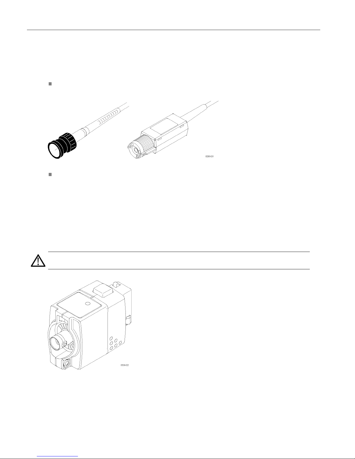
BNC – this connection is a shielded 50 Ω coaxial cable with an outer ground connection and center signal pin. The BNC
interface is used on the P5200A probe, which allows you to connect directly to most ground-referenced oscilloscopes.
TekP r o be
the probe tip. This interface is used on the P5202A, P5205A, and P5210A probes, and many Tektronix oscilloscopes.
These probes can also be used with Tektronix oscilloscopes that use the TekVPI-interface, by connecting through an
optional
TPA-BNC Adapter
Level 2 – this interface adds probe communications with the oscilloscope to accomplish calibrated offset at
TPA-BNC Adapter.
ng Information
The TPA-BNC Adapter is an optional accessory that enables you to use existing TekProbe-interface probes with oscilloscopes
that feature the TekVPI probe interface. The adapter recognizes TekProbe-interface probes and supplies the necessary
power, serial communication, and offset control as used by the connected TekProbe product accessory.
WARNING. To reduce risk of shock or fire, do not exceed the ratings of the TPA-BNC adapter; it is not intended to be
connected to voltages above 30 VAC, 42 Vpk, or 60 VDC. F or BNC probes, connect the probe directly to the oscilloscope.
1 P5200A Series High Voltage Differential Probes Instruction Manual
Page 21

Connecting to the Instrument
P5200A Probe
The P 5200A probe requires an external AC adapter to power the internal circuitry. Install the P5200A probe as follows:
1. Connect the output of the probe to the BNC input of the oscilloscope or other measurement instrument. The
measurement instrument input must be ground-referenced (not floating).
Probe Operating
Information
2. Connect the power cord to the AC adapter.
3. Connect the output of the AC adapter to the DC input jack located on the output lead of the probe. All of the LEDs on the
probe briefly light to confirm power-on, and then indicate the settings from the previous session.
4. A d just the vertical offset (or position) of the measurement instrument input.
5. S elect the proper range setting. For example, when using the P5200A probe, to achieve higher resolution and less noise
when measuring signals below 130 V
, switch the attenuation to 50X. If the overrange indicator lights or flashes, the
pk
output signal may not be accurate. Use the 500X setting instead.
If you want the oscilloscope to display the actual probe voltage instead of a scaled value, you must match the attenuation
setting of the oscilloscope to the probe attenuation setting. Use the on-screen Probe Setup menu on the oscilloscope;
the access method varies depending on oscilloscope model.
For example, on DPO/MSO4000 series oscilloscopes, press the front-panel channel number button and then press the
More button on the lower bezel until Probe Setup is highlighted. The oscilloscope attenuation setting displays in the
Probe Setup menu. Change the attenuatio n by turning the multipurpose knob.
WARNING. To avoid electrical shock, observe proper safety precautions when working with voltages above 60 VDC or
30 VAC
. T hese voltage levels pose a shock hazard. Use only the accessories specified for the probe that you a re using.
RMS
Make sure that the accessories are fully mated before connecting or disconnecting.
To avoid electrical shock or fire, make sure the test leads are in good condition. The input leads and extender leads have a
jacket wear indicator which becomes visible if the wire jacket becomes excessively worn. If the wear indicator is visible, do
not use the probe. Contact Tektronix Service for repair or replacement.
To avoid electrical shock or fire, keep the prob
e body and output cable of the probe away from the circuits being measured.
The probe body and output cable are not intended to be in contact with the circuits being measured.
6. Using the appropriate probe accessories, connect the inputs of the probe to the circuit points to be measured.
P5200A Series High Voltage Differential Probes Instruction Manual 2
Page 22

Probe Operating
Connecting P5202A, P5205A, & P5210A Probes to Oscilloscopes that feature the VPI Interface
1. Connect the TPA-BNC adapter to the oscilloscope.
Information
2. Connect the probe to the input of the adapter.
3. Turn the probe connector clockwise to secure it. All of the LEDs on the probe briefly light to confirm power-on, and then
indicate the settings from the previous session.
4. Adjust the vertical offset (or position) of the oscilloscope input.
NOTE. Do not attempt to adjust the offset adjustment in the probe compensation box; it is factory-preset to optimize the
range of the electronic adjustment. To make the offset adjustment, refer to the procedures. (See page 45, Offset Zero.)
5. Select the proper range setting. For example, when using the P5202A probe, to achieve higher resolution and less
noise when measuring signals below 64 V
, switch the attenuation to 20X. If the overrange indicator lights or flashes,
pk
the output signal may not be accurate. Use the 200X range setting instead.
WARNING. To avoid electrical shock, observe proper safety precautions when working with voltages above 60 VDC or
30 VAC
. These voltage levels pose a shock hazard. Use only the accessories specified with the probe that you are using.
RMS
Make sure that the accessories are fully m ated before connecting or disconnecting.
WARNING. To avoid electrical shock or fire, make sure the test leads are in good condition. The input leads and extender
leads have a jacket wear indicator which becomes visible if the wire jacket becomes excessively worn. If the wear indicator is
visible, do not use the probe. Contact Tektronix Service for repair or replacement.
6. Using the appropriate probe accessories, connect the inputs of the probe to the circuit points to be measured.
WARNING. To avoid electrical shock or fire, keep the probe body and output cable of the probe away from the circuits being
measured. The probe body and output cable are not intended to be in contact with the circuits being measured.
3 P5200A Series High Voltage Differential Probes Instruction Manual
Page 23

Disconnecting from the Instrument
Probe Operating
Information
WARNING. To a v
the instrument.
oid electrical shock, disconnect the probe inputs from the circuit before disconnecting the probe from
P5200A
1.Turn the probe connector counterclockwise.
2. Pull straight out.
P5202A, P5205A, P5210A
1. Turn the probe co
counterclockwise.
2. Pull straight out.
3. Press the latch
4. Pull straight out.
nnector
button on the adapter.
P5200A Series High Voltage Differential Probes Instruction Manual 4
Page 24

Probe Operating
Information
Probe Controls
The P5200A Series probes have s everal features that make probing and measurement a simpler task. F am iliarize yourself
with the controls shown on the following pages. The attenuation ranges differ between probe models.
Overrange Indicator
The overrange indicator lights red if the
voltage of the input signal exceeds the
linear range of the range setting. When this
happens, the signal on the probe output
does not accurately represent the signal on
the probe input.
WARNING. The Overrange indicator
does not detect overrange condition of
common-mode voltages or voltage-to-earth
potential at the probe inputs. The Overrange
indicator only detects differentially between
the + and – inputs (not relative to ground).
Do not exceed the common-mode voltage
or input voltage-to-earth ratings of the probe
when taking measurements. (See page 27,
Overrange Detection.)
If you are not sure, make a single-ended
measurement of each point you are intending
to measure differentially first. Make a
single-ended measurement by tying one
input lead to ground (the "–" input) and then
connecting the other lead (the “+" input) to
the points of interest, one at a time.
Attenuation Button and Indicators
Press the button to select between the
voltage range (attenuation) settings of the
probe. The range is indicated by two LEDs
on the probe and may be displayed on
the oscilloscope screen, depending on the
oscilloscope model.
P5200A models only: To display the actual
probe voltage instead of a scaled value, you
must match the attenuation setting of the
oscilloscope to the probe attenuation setting.
Use the on-screen Probe Setup menu on the
oscilloscope to change the setting.
The Overrange LED lights if the applied
voltage exceeds the selected range. To
extinguish the LED, select a higher range.
If a higher range is not available, do not
attempt to take the measurement.
5 P5200A Series High Voltage Differential Probes Instruction Manual
Page 25

Bandwidth Limit Button and
Indicators
Press the button to limit the probe bandwidth
to 5 MHz. 5 MHz is close to the switching
frequency of most switching transistors
(FETs) in switch mode power supplies
(SMPS).
The5MHzfilter assists in the characterization
and testing of power supplies in switch mode
by removing all high frequency content, noise
and harmonics from the measurement.
Press the button again to return to the Full
position, which selects the full specified
bandwidth of the probe.
Audible Overrange On/Off Button
and Indicators
Probe Operating
Information
Press the
enable an audible alarm that indicates when
the measured signal exceeds the selected
range. P
OFF LED and disable the audible feature.
button to light the ON LED and
ress the button again to light the
P5200A Series High Voltage Differential Probes Instruction Manual 6
Page 26

Probe Operating
Information
Functional Check
Using accessories that are shipped with your P5200A S eries probe and a source that supplies AC line voltage, perform the
following procedure.
WARNING. To reduce risk of shock or fire, ensure that the accessories are fully mated before you connect to voltage
sources above 42 Vpk.
1. Connect the output of the probe to the oscilloscope input channel.
2. Connect the probe inputs to the AC voltage source.
3. Set the probe attenuation range to the highest setting and perform the check as each row of the following table indicates.
Figure 1: Funct
Input 1
(+ or –)
Hot
ional check setup
Input 2
Mode Range setting
(– or +)
Ground or Neutral Differential High (1000X,
500X, or 200X)
Hot
Ground or Neutral Differential Low (100X,
50X, or 20X)
Hot
1
If a DC offset voltage is present, zero th e DC offset. (See page 45, Offset Zero.)
Hot (same
connection)
Common
Mode
High or low No signal
Check
Measurement instrument displays or indicates
the line voltage
Measurement instrument displays or indicates
the line voltage. Overrange indicator lights if
the input is ~20% over
1
7 P5200A Series High Voltage Differential Probes Instruction Manual
Page 27

Accessories
The P5200A Series probes include standard accessories that make connecting to your circuit an easier task. Other
accessories are available and are described in the Optional Accessories section. (See page 15, P5200A Series Probes
Optional Accessories.)
Connecting to the Circuit
Make the connections to your circuit using the integral input leads or the accessories that best fit your application.
WARNING. To reduce risk of shock or fire, do not exceed either the voltage rating or category ratings of the probe or the
probe acces
sory, whichever is the lesser of the two. Use only the accessories provided with the probe.
Accessories
To avoid el
away from the shaded area shown in the accessory illustrations below.
To avoid electrical shock or fire, make sure the test leads are in good condition. The input leads and extender leads have a
jacket wear indicator which becomes visible if the wire jacket becomes excessively worn. If the wear indicator is visible, do
not use th
To avoid e
The probe body and output cable are not intended to be in contact with the circuits being measured.
Integra
The integral input leads extend ~9 in (0.23 m)
from the probe body and have shrouded
male ban
directly to your circuit, or use the extender
leads and the other accessories shown on
the fol
ectric shock when using the probe or accessories, keep your fingers behind the finger guard of the probe body and
e probe. Contact Tektronix Service for repair or replacement.
lectrical s hock or fire, keep the probe body and output cable of the probe away from the circuits being measured.
l Input Leads
ana plugs. Connect the leads
lowing pages.
P5200A Series High Voltage Differential Probes Instruction Manual 8
Page 28

Accessories
P5200A, P5202A, & P5205A Probe Standard Accessories
Extender Leads
These cables e
by ~67 in (1.5 m). The banana ends connect
to all of the clip accessories that are included
with the probe
One pair of extender leads are included with
the probes.
Maximum rati
2300 V CAT I *
1000 V CAT III
* See Specifi
Transient (OVT) rating for the probe that you
are using.
Reorder Te
196-3523-xx (one pair)
Hook Clips (AC280-FL)
Plug the probe test leads into the banana
plug conn
expose the hook clip and then clasp it around
the circuit test point.
Maximum
1000 V CAT III
600 V CAT IV
One pai
probes.
Reorder Tektronix part number:
AC280-
xtend the reach of the probes
s.
ngs:
cations for the Over-Voltage
ktronix part number:
ectors. Squeeze the grips to
ratings:
r of hook clips is included with the
FL (one pair)
9 P5200A Series High Voltage Differential Probes Instruction Manual
Page 29

Pincer Clips (AC283-FL)
The plunger probes have long probe sleeves
with retracti
ng hooks. These probes safely
connect to recessed test points that are
otherwise difficult to reach.
Maximum rati
ngs:
1000 V CAT III
600 V CAT IV
One pair of p
incer clips is included with the
probes.
Reorder Tektronix part number:
AC283-FL (o
ne pair)
Accessories
Alligator
Clips (AC285-FL)
These large insulated alligator clips c onnect
to many circuit components.
Maximum r
atings:
1000 V CAT III
600 V CAT IV
One pair
of clips is included with the probes.
Reorder Tektronix part number:
AC285-FL (one pair)
P5200A Series High Voltage Differential Probes Instruction Manual 10
Page 30

Accessories
P5210A Probe Standard Accessories
WARNING. To av
CAT IV circuits. Refer to the ratings tables in the beginning of the manual. (See Table i on page x.) (See Table ii on page xiii.)
To avoid risk of electric shock or fire, when using the P5210A test probe or hook tip accessories with the P5200A, P5202A
and P5205A probes, do not use on circuits above 1000 V.
Use only accessories that are rated for the application. Substitution of other accessories may create a shock or burn hazard.
Keep the prob
Extender Leads
These leads
by ~67 in (1.5 m), which allow you to reach
connections as far as 3 m apart. Be sure to
use both ex
leads are the same length.
However, with longer lead length, differential
noise ind
Also, because of the added inductance of the
leads, v oltage measurements at frequencies
above app
as precise. For best performance, use the
20 MHz or lower-bandwidth filter on your
oscillo
The male banana-plug ends connect to the
test probes that are included with the probes.
Maximum
1000 V CAT III
600 V CAT IV
Reorde
(one pair)
uced into the input leads is greater.
scope.
r Tektronix part number: 196-3523-xx
oidriskofelectricshockorfire, do not use the P5210A test probe or hook tip accessories on CAT III or
e body and accessories clean to reduce the risk of shock due to surface conduction.
extend the reach of the probes
tension leads so that the input
roximately 10 MHz may not be
ratings:
A Accessory Kit
P5210
Kit includes one pair of each of the
accessories shown on the following pages:
Test Probes (TATP)
Small Hook Tips (TASH)
Large Hook Tips (TALH)
Reorder Tektronix part number: 020-3070-xx
11 P5200A Series High Voltage Differential Probes Instruction Manual
Page 31

Test Probes (TATP)
Use the test probes to browse multiple test
points or to co
nnect the test leads to the
hook tips.
1. The test probe tip is a 6-32 threaded post
that accepts the large and small hook
tips provide
d with the probe.
Accessories
2. The finger gua
rd provides protection
when the hook tips are not being used.
Keep your fingers behind the finger
guard whene
ver possible to reduce the
risk of a shock from the circuit under test.
3. Connect the back end of the test probe
to the input test leads of the probe.
Maximum ra
tings:
2300 V CAT I*
1000 V CAT II
*SeeSpec
ifications for the Over-Voltage
Transient (OVT) rating for the probe that you
are using.
WARNING
. To prevent arc flash, use
caution when probing circuits with raised
components. Avoid getting the metal shell
n components of different potentials.
betwee
Use TASH for probing in hard to reach areas.
WARNING. To prevent arc flash, do not use
st probe or hook tips on CAT III circuits.
the te
To probe CAT III circuits, use the AC280-FL,
AC283-FL, or AC285-FL.
P5200A Series High Voltage Differential Probes Instruction Manual 12
Page 32

Accessories
Small Hook Tip (TASH)
Use the small hook tip for making
connections t
component leads.
Screw the small hook tip onto the TATP test
probe. To use
body and pull the tip shield back. Hook the
tip onto the circuit and release the shield.
o small conductors such as
the hook tip, hold the probe
WARNING. To
reduce the risk of shock
when measuring voltages above 1000 V,
always keep your fingers behind the tactile
indicator.
Maximum ratings:
2300 V CAT I
*
1000 V CAT II
* See Specifications for the Over-Voltage
Transien
t (O VT) rating for the probe that you
are using.
LargeHookTip(TALH)
Use the large hook tip when working with
omponents such as bolt terminals
larger c
and bus bars typically found in power
distribution equipment.
he large hook tip onto the TATP test
Screw t
probe and then clamp the hook tip onto the
circuit.
NG. To reduce the risk of shock
WARNI
when measuring voltages above 1000 V,
always keep your fingers behind the tactile
ator.
indic
Maximum ratings:
VCATI*
2300
1000 V CAT II
* See Specifications for the Over-Voltage
nsient (OVT) rating for the probe that you
Tra
are using.
13 P5200A Series High Voltage Differential Probes Instruction Manual
Page 33

Accessories
P5200A Probe Power S upply and Power Cord Options
The P5200A Probe requires an external DC power supply, which is included with the probe. Power cord options are available
for international locations and are listed in the table below.
Table 1: P5
Item Descript
1
2
200A power supply and power cord options
POWER SUP
IN;9 VDC 2 A, CABLE WITH BARREL CONNECTOR OUT;SAFETY CONTROLLED
OPTION A0: CABLE ASSY PWR; 3,18 AWG, 250V/10A, 98.0 L, STR, IEC320,
RCPT X NEMA 5-15P, US, SAFETY CONTROLLED,
OPTION A1: CABLE ASSY, PWR; 3,0.75MM SQ, 250V/10A, 99.0 L, STR IEC320,
RCPT, E
OPTION
IEC320, RCPT X 13A, FUSED UK PLUG (13A FUSE), UNITED KINGDOM, SAFETY
CONTROLLED
OPTION A3: CABLE ASSY, PWR; 3,1.0 MM SQ, 250V/10A, 2.5 METER, STR,
20, RCP T, AUSTRALIA, SAFETY CONTROLLED, INSULATED PINS
IEC3
ON A5: CABLE ASSY, PWR; 3,1.0MM SQ,250V/10A, 2.5 METER, STR,
OPTI
IEC320, RCPT, SWISS, SAFETY CONTROLLED
OPTION A6: CABLE ASSY, PWR; 3,125V/7A, JAPAN, 98 LONG, STR, NEMA 5-15P
PLUG X IEC320/C-13 RECEPTACLE, SAFETY CONTROLLED
OPTION A10: CABLE ASSY, PWR; 3,1.0MM SQ, 250V/10A, 2.5 METER, STR,
C320, 3C CERTIFICATION, RCPT, CHINA, SAFETY CONTROLLED
IE
TION A11: CABLE ASSY,PWR; 3,1.0MM SQ,250V/6A,2.5 M ETER, S TR,
OP
IEC320/C13, RCPT,PLUG, INDIA
OPTION A12: CABLE ASSY, PWR; 3,1.00MM SQ, 250V/10A , 2.5 METER, STR,
IEC320/C13 CERTIFICATION, RCPT, BRAZIL, SAFETY CONTROLLED
ion
PLY: AC-DC, 18W, DESKTOP;90-264 VAC, 47-63 HZ, IEC320-C14
UROPEAN, SAFETY CONTROLLED
A2: CABLE ASSY, PWR; 3,1.0 MM SQ, 250V/10A, 2.5 METER, STR,
Tektroni
119-7758-xx
161-006
161-0066-09
161-0066-10
161-0066-13
161-0154-00
161
161-0304-00
161-0400-00
1
x part number
6-00
-0298-00
61-0357-00
P5200A Series High Voltage Differential Probes Instruction Manual 14
Page 34

Accessories
P5200A Series Probes Optional Ac cessories
WARNING. To re
probe accessory, whichever is the lesser of the two. Use only the accessories provided with the probe or the optional
accessories shown below.
To avoid electric shock when using the probe or accessories, keep your fingers behind the finger guard of the probe body and
away from the
To avoid elec
jacket wear indicator which becomes visible if the wire jacket becomes excessively worn. If the wear indicator is visible, do
not use the probe. Contact Tektronix Service for repair or replacement.
To avoid electrical shock or fire, keep the probe body and output cable of the probe away from the circuits being measured.
The probe bo
TPA-BNC Ad
This optional accessory enables you to use
the P5202A, P5205A, and P5210A probes
with osci
probe interface.
The TPA-BNC Adapter allows the
oscillos
power and communication to these
TekProbe-interface probes.
NOTE. Th
directly to the BNC connector on the TekVPI
interface, so they do not require this adapter.
lloscopes that feature the TekVPI
cope to recognize and provide
duce risk of shock or fire, do not exceed either the voltage rating or category ratings of the probe or the
shaded area shown in the accessory illustrations below.
trical shock or fire, make sure the test leads are in good condition. The input leads and extender leads have a
dy and output cable are not intended to be in contact with the circuits being measured.
apter
e P5200A probes connect
WARNIN
do not exceed the ratings of the TPA-BNC
adapter. Do not connect the adapter to
volta
G. To reduce risk of shock or fire,
ges above 30 VAC, 42 Vpk, or 60 VDC.
15 P5200A Series High Voltage Differential Probes Instruction Manual
Page 35

Handheld Probes (TP175-FL)
These probes plug onto the banana input
leads and exte
nder leads. The tips are
threaded to accept tip accessories that are
included with the probe.
The insulator
sheath at the probe tip extends
and retracts into CAT III and CAT IV-rated
spacings. Twist the probe body past the
detent at eac
h end of the twist to lock the
probe into the CAT setting.
WARNING. Always verify that the p robe
body is lock
ed into position before taking
measurements. Do not use in the unlocked
neutral position.
Ratings:
1000 V CAT I
I
1000 V CAT III
10 A
Order Tek
tronix part number:
TP175-FL (one pair)
Accessories
P5200A Series High Voltage Differential Probes Instruction Manual 16
Page 36

Accessories
Pogo Pin Tip Adapters & Tips
These insulated adapters hold pogo pins and
screw on to the
handheld probes.
WARNING. To prevent electrical shock,
tighten the p
the TP175-FL probe.
Two pairs of pogo pin types are included
with the adapters; one pair have sharp, cone
points and t
for embedding in soft conductors.
WARNING. The pogo pins have very s harp
points. To
carefully when you install and remove them.
WARNING. To prevent risk of arc flash,
ensure th
inserted into the adapter. Verify that the
exposed metal portion of the tip is 19 mm
(0.75 in
threaded tips of the TP175-FL
ogo pin tip adapter completely to
he other pair have serrated edges
prevent injury, handle the pins
at the pogo pin is completely
)orless.
WARNING. The probe input rating is derated
to 150 V CAT II, 0.1 A, when used with the
THDP an
d TMDP series probes. Do not use
this pogo pin adapter to measure v oltages
that exceed this rating.
um ratings:
Maxim
150 V CAT II
0.1 A
der Tektronix part number:
Reor
020-3107-xx (includes 2 Tip Adapters,
2 Cone-Tip Pogo Pins, &
rated-Tip P ogo Pins)
2 Ser
17 P5200A Series High Voltage Differential Probes Instruction Manual
Page 37

Accessories
Extended Test P
robe Adapters
These adapters screw on to the threaded tips
of the handheld probes.
Use these adap
ters to reach into dense
circuitry. The sharp tips can contact small
component leads and circuit board features.
WARNING. The
probe input rating is derated
to 300 V CAT II, 1 mA, when used with the
THDP and TMDP series probes. Do not
use this ext
ended probe adapter to measure
voltages that exceed this rating.
WARNING. The tip on this adapter is very
sharp. To p
revent injury, do not touch the tip.
Maximum ratings:
300 V CAT II
3A
Order Tektronix part number:
012-1724-xx (one pair)
Crocodile Clips
The crocodile cl
ips connect easily to large
bolts or bus bars. The connectors are double
insulated for safety. The clips screw on to the
threaded tips o
f the handheld probes.
Maximum ratings:
1000 V CAT III
10 A
One pair of clips is included with the probes.
Order Tektronix part number:
344-0670-xx
(one pair)
P5200A Series High Voltage Differential Probes Instruction Manual 18
Page 38

Accessories
Table 2 : Voltage derating for P5200A Series probes optional accessories
Combined probe
and input voltage-to-earth ratings
and accessory common-mode voltage
1,2
Accessory P5202A P5200A & P5205A P5210A
3
Handheld pro
(TP175-FL)
Pogo pin tip adapters w ith either style tips
bes
450VCATI
300 V CAT II
1000 V CAT II
600 V CAT III
1000 V CAT I
1000 V CAT III
150 V CAT II 150 V C AT II 150 V C AT II
(020-3107-xx)
Extended test probe adapters
(012-1724-xx)
Crocodile
clips
(344-0670-xx)
1
The operating altitude of the probe is derated to 2000 m (6560 ft) when used with these accessories.
2
3
ge rating and CAT rating are derated to the voltage in this table when used with these accessories.
The volta
When using the TP175-FL test probes in CAT III circuits, the tip must be in the retracted position to prevent risk of arc fl ash. The exposed metal tip
is about 3.7 mm (0.15 in) in the retracted position.
300VCATI
300 V CAT II
450VCATI
300 V CAT II
300 V C AT II 300 V CAT I
300 V C AT II
1000 V CAT I
600 V CAT III
I
1000 V CAT I
1000 V CAT III
19 P5200A Series High Voltage Differential Probes Instruction Manual
Page 39

Accessories
TPH1000 Probe H
older
The TPH1000 probe holder allows you to
make a hands-free connection when using
the optional h
andheld probes (TP175-FL).
The probe holder can also be used with
many other Tektronix probes.
You have two op
tions for taking hands-free
differential measurements:
You can use the handheld probes with
two TPH1000 probe holders (required if
the test poin
For test poi
ts are >1 inch apart).
nts <1 inch apart, use the
handheld probes with the optional
THV-Browser (shown on the following
page).
To use the probe holder, do the following:
1. Insert the probe into one of the holder
openings
so that the Tektronix logo faces
the circuit under test.
2. Slide the probe forward to secure it.
CAUTION. To avoid personal injury, always
nd remove the probe by gripping the
insert a
handheld section of the probe.
3. Position the base of the probe holder on
your circuit where it can maintain stability
ontacting the test point.
while c
The weight of the probe holder keeps the
probeinplace.
NG. Do not use the probe holder
WARNI
without the rubber feet; internal metal would
be exposed which presents a shock hazard.
ION. If you are probing circuitry
CAUT
with dense contacts such as IC pins,
Tektronix recommends that you use insulated
be tip accessories designed to prevent
pro
short-circuiting adjacent IC pins or circuitry.
Order Tektronix part number:
H1000
TP
P5200A Series High Voltage Differential Probes Instruction Manual 20
Page 40

Accessories
THV-Browser
The THV-Browser allows you to
set and lock the spacing between
two handheld p
browse your circuit with one hand.
Handheld Browsing.
1. P lace each TP175-FL
2. Loosen the thumb screw and
3. Tighten the thumb screw.
You can now browse your circuit.
robe tips, and then
handheld probe into the
cavity and then slide the probe
forward to lock it into place.
adjust the spacing between
the probe tips. Graticules
near the thumb screw indicate
the spacing. The maximum
spacing is ~1 in (2.54 mm).
WARNING. To avoid injury or
short circuits, do not drop the
THV-Browser on high voltage
circuitry. The browser contains
metal components.
Hands-free Probing.
If you want a stationary, hands-free
connection, attach the browser to
the TPH1000 probe holder:
4. Aligntheslotsonthetopofthe
probe holder with the pins on
the bottom of the browser.
5. Rotate the browser 90° and
making sure that the Tektronix
logo on the probe holder faces
the circuit under test.
6. P osition the probe tips on your
test points so that you can set
the holder on a stable surface.
Order Tektronix part number:
THV-Browser
21 P5200A Series High Voltage Differential Probes Instruction Manual
Page 41

Accessories
Tektronix 1103
Supply.
for performing service procedures on the
P5202A, P5205A
The 1103 power supply provides power to
the probe and routes the probe output signal
through a BNC c
of the supply.
Order Tektronix part number:
1103
Probe Power
Use the 1103 power supply
, and P5210A probes.
onnector on the front panel
Replacement Label (Safety Item;
Service Only).
the openings to the service-only adjustments
on the back of the probe. To maintain
the safety of the probe, the label must be
replaced after service adjustments are made
to the probe.
If the original label becomes damaged or
lost, order a replacement label.
NOTE. This label is only replaceable on
units with serial numbers C020000 and
above
This reusable label covers
Order Tektronix part number:
335-2913-xx
P5200A Series High Voltage Differential Probes Instruction Manual 22
Page 42

Options
Options
Service O ption s
Option C3. Calibration Service 3 years
Option C5. Calibration Service 5 years
Option D1. Calibration Data Report
Option D3. Calibration Data Report, 3 years (with Option C3)
Option D5. Calibration Data Report, 5 years (with Option C5)
Option R3. Repair Service 3 years
Option R5. Repair Service 5 years
23 P5200A Series High Voltage Differential Probes Instruction Manual
Page 43

Operating Basic
s
Operating Bas
To help you use the P5200A Series High Voltage Differential Probes safely and effectively, this section provides important
information about safety limits, operating characteristics, and probing techniques.
ics
Operating Characteristics and Probing Techniques
This section explains the operating characteristics of the P5200A Series High Voltage Differential Probes and includes
techniques
Operating Limits
The probes have two operating ranges that you select with the ATTEN button. These ranges set the maximum differential
voltage that can be measured. The ranges and voltage lim its differ between probe models. (See Table 3.)
Table 3: Differential voltage limits (Peak)
Probe model Voltage limit Overload trip level Voltage limit Overload trip level
P5200A (50X/500X)
P5202A (20X/200X)
P5205A (50X/500X)
P5210A(100X/1000X)
that you can use to maximize the performance of the probe.
Low attenuation range
(20X/50X/100X)
130 V >140 V 1300 V >1400 V
64 V >70 V 640 V >700 V
130 V >140 V 1300 V >1400 V
560 V >600 V 5600 V >6000 V
High attenuation range
(200X/500X/1000X)
The input signals that you attempt to m easure must be considered both for the differential potential between each other
and for the amplitude on each input with respect to ground (the common mode voltage specification). The maximum
common mode voltage limits vary between probes, from 450 V for the P5202A, to 2300 V for the P5210A probe. You
should consider both specifications when choosing a probe for your measurement task. Some examples that illustrate this
are shown on the following pages.
P5200A Series High Voltage Differential Probes Instruction Manual 24
Page 44

Operating Basic
Measurement Ex ample s
Example 1. Consider a case where you need to measure two sinusoidal waveforms that are 180° out of phase with each
other, each with an amplitude of 1000 V
s
with no DC offset (centered at 0 V). (See Figure 2.)
pk
Figure 2: Measuring two equal-amplitude waveforms that are 180 degrees out of phase
If both waveforms are at the same voltage potential, then the differential measurement would be 2 times the individual signal
inputs (in this example, 2000 V
probes, the P 5210A probe is capable of measuring this signal. (See Table 6 on page 29.) For reference, the rms
Series
). Looking at the maximum measurable differential voltage specifications for the P5200A
pk
values of the Common-Mode Voltage and Voltage-to-Earth ratings and Maximum Input Signals for each probe model are
showninthefi gure above.
25 P5200A Series High Voltage Differential Probes Instruction Manual
Page 45

Operating Basic
Example 2. Next, assume that the same waveforms from the previous example are 120° out of phase with each other.
(See Figure 3.)
Although this is a lower potential between the inputs than in example 1, it still exceeds the differential rating (1300 V
P5200A and P5205A probes, so you must use the P5210A.
This phase relationship yields a maximum differential of 1.732 times the individual signal inputs, or 1732 V
)ofthe
pk
s
.
pk
Figure 3: Measuring two equal-amplitude waveforms that are 120 degrees out of phase
e examples with equal-amplitude signals on the inputs, the P5200A and P5205A probes can measure up to 1300 V/2
In thes
= 650 V
(460 V
pk
) on each input when the signals are 180° apart, and 1300 V/1.732 = 750 Vpk(530 V
rms
) when 120° apart.
rms
When you are taking these types of measurements, to prevent exceeding the maximum differential input voltage for the
fic probe model that you are using, refer to the respective figures for the maximum input signal voltages (V
speci
rms
).
Example 3. Your task is to measure two AC waveforms of the same phase, each with an amplitude of 300 V. However, one
waveform is centered on ground (– input), and the other is centered on an offset of 400 VDC (+ input). The common mode
voltage is the 300 V
taken into account for both inputs. The voltage-to-earth is 300 V
is 700 V
(the 300 VAC
rms
of the P5202A probe, so it cannot be used for taking this measurement. In this case, you must use another probe; the
next closest being either the P5200A or P5205A probe.
, but the maximum voltage-to-earth (the common mode voltage plus the signal waveform) must also be
rms
on the (– input), but on the (+ input), the voltage-to-earth
rms
plus the 400 VDC
rms
). Thus the (+ input) exceeds the maximum input voltage-to-earth rating
rms
P5200A Series High Voltage Differential Probes Instruction Manual 26
Page 46

Operating Basic
Overrange Detection
Differential voltage outside the operating range will overdrive the c ircuitry of the probe and distort the output signal. When
this differential overrange occurs, the probe detects the condition and lights the overrange indicator. With the Audible
Overrange ON, the probe will also emit an audible alarm.
WARNING. The Overrange indicator does not detect an overrange condition of common-mode voltages or voltage-to-earth
potential at the probe inputs. The Overrange indicator only detects differentially between the + and – inputs (not relative to
ground). Do not exceed the Common-Mode Voltage or Input Voltage-to-Earth ratings of the probe when taking measurements.
If you are not sure, first take a single-ended measurement of each point that you are intending to measure differentially.
Take a single-ended measurement by tying one input lead to ground (the – input) and then connecting the other lead (the +
input) to the points of interest, one at a time.
Common-Mode Rejection
The common-mode rejection ratio (CMRR) is the specified ability of a probe to reject signals that are common to both inputs.
More precisely, CMRR is the ratio of the differential gain to the common-mode gain. The higher the ratio, the greater the
ability o
s
f probe to reject common-mode signals.
Common mo
500 V
50 mV
Twistin
de rejection decreases as the input frequency increases. For example, if you apply a 60 Hz line voltage of
to both input leads of the probe, the probe rejects the signal by 80 dB (typical) and the signal appears as only a
p-p
signal on the oscilloscope screen.
p-p
g the Input Leads
Twisting the input leads helps to cancel noise from high-EMI environments that is induced into the input leads.
Probe Loading
When you touch your probe tip to a circuit element, you are introducing a new resistance, capacitance, and inductance into
e circuit. Frequency and impedance of the source determine how much the probe loads the circuit you are measuring. As
th
the frequency of the source starts to increase beyond 1 kHz, the input impedance of the probe begins to decrease.
The lower the impedance of the probe relative to that of the source, the more the probe loads the circuit under test. For a
graph of frequency versus input impedance, refer to the Specifications section. As the graph shows, the probes have virtually
loading effect on sources with relatively low impedance and low frequency.
no
27 P5200A Series High Voltage Differential Probes Instruction Manual
Page 47

Specifications
Specification
The specifications shown apply to the P5200A Series probes installed on Tektronix MSO/DSO4000 oscilloscopes. When a
probe is used with another oscilloscope, the oscilloscope must have an input impedance of 1 MΩ and a bandwidth equal
to or greater than the probe. The probe must have a warm-up period of at least 20 minutes and be in an environment
that does not exceed the limits described. (See Table 5.) The probe calibration should be run on the host instrument
before verifying the warranted probe specifications. Specifications for the P5200A Series probes fall into three categories:
warranted, typical, and nominal characteristics.
s
Warranted Specifications
Warranted c
(See Table 4.)
Table 4: Wa
Specification P5200A P5202A P5205A P5210A
Rise time
(small signal, 10–90%,
+20 °C to +30 °C)
Gain accuracy ±2%
1
haracteristics describe guaranteed performance within tolerance limits or certain type-tested requirements.
rranted electrical specifications
≤7.0 ns
Output may be slew rate limited for large amplitude signals.
1
≤3.5 ns
≥240 V/ns (200X))
(slew rate
≤3.5 ns1(slew rate
≥590 V/ns (500X))
≤7.0 ns
Table 5: Warranted environmental specifications
Specification
Temperature
Operating 0 °C to 40 °C (32 °F to +104 °F)
Nonoperating
Humidity
Operating 5 to 85% RH (Relative Humidity) 0 °C to +40 °C (32 °F to + 104 °F)
Nonoperating
Altitude
Operating 3,000 m (10,000 ft)
Nonoperating
P5200A P5202A P5205A P5210A
–30° C to +70° C ( –22 °F to +158 °F)
5% to 85% RH at up to +40° C (+104 °F)
5% to 45% RH above +40° C up to +70° C (+104 to +158 °F)
up to 15,240 m (50,000 ft)
P5200A Series High Voltage Differential Probes Instruction Manual 28
Page 48

Specifications
Typical Specifications
Typical specifications describe typical but not guaranteed performance.
Table 6: Typical electrical specifications
Specification
Maximum measurable
differential voltage
rms
1
)
(DC + Peak AC)
(V
Maximum c ommon mode
voltage (DC + Peak AC)
Maximum input
voltage-to-earth (V
rms
3
)
CAT I Maximum Rated
P5200A P5202A P5205A P5210A
50X: ±130 V
500X: ±1300 V
50X: 92 V
500X: 920 V
50X: ±130 V
3
500X: ±1300 V
1000 V CAT II
600 V CAT III
rms
rms
20X: ±64 V
200X: ±640 V
20X: 45 V
rms
200X: 450 V
20X: ±64 V
200X: ±640 V
300 V C AT II
450 V CAT I
rms
50X: ±130 V
500X: ±1300 V
50X: 92 V
500X: 920 V
rms
rms
50X: ±130 V
500X: ±1300 V
1000 V CAT II
600 V C AT III
NA 1760 V NA 2250 V
100X: ±560 V
1000X: ±5600 V
100X: 396 V
rms
1000X: 2650 V
100X: ±320 V
1000X: ±3200 V
1000 V CAT III
2300 V CAT I
Overvoltage Transient
(OVT) (V
1
2
3
4
4
)
Pk
This is the maximum measurable range between the (+) and (-) inputs of the probe. Beyond these limits, the output could be clipped. (See Figure 4.)
This rating assumes that the common mode voltage and input voltage-to-earth ratings are not exceeded.
The maximum common-mode and input voltage-to-earth ratings are the maximum amount that each input lead (+/-) can be from ground.
Applies to CAT I ratings only. The OVT peak is typically measured on top of the Peak Working Voltage.
rms
2
Figure 4: Specification table footnotes referring to the probe input limits shown on each probe label
29 P5200A Series High Voltage Differential Probes Instruction Manual
Page 49

Table 7: Typical electrical specifications
Specifications
Specification
Bandwidth (-3
dB)
Offset zero
(+20 °C to +30 °C)
P5200A P5202A P5205A P5210A
DC to 50 MHz DC to 100 MHz DC to 100 MHz DC to 50 MHz
±10 mV
(50X & 500X)
output referred
±200 mV (20X)
±2 V (200X)
input referred
±500 mV (50X)
±5 V (500X)
input referred
±1 V (100X)
±10 V (1000X)
input referred
Input resistance
Between inp
Between ea
uts
ch input
10 MΩ ±2% 5 MΩ ±2% 10 MΩ ±2% 40 MΩ ±2%
5MΩ ±2% 2.5 MΩ ±2% 5 MΩ ±2% 20 MΩ ±2%
and ground
Input capa
citance
Between inputs <2.0 pF <2.0 pF <2.0 pF <2.5 pF
Between each input
<4.0 pF per side <4.0 pF per side <4.0 pF per side <5.0 pF per side
and ground
Common Mode
on Ratio
Rejecti
(20–30°C)
DC: >80 dB
100 kHz:
>60 dB
3.2 MHz: >30 dB
50 MHz: >26 dB
DC: >80 dB
100 kHz:
>60 dB
3.2 MHz: >30 dB
100 MHz: >26 dB
DC: >80 dB
100 kHz:
>60 dB
3.2 MHz: >30 dB
100 MHz: >26 dB
DC: >80 dB
100 kHz:
3.2 MHz: >30 dB
50 MHz: >26 dB
Propagation delay 21 ns 18 ns 18 ns 18 ns
DC offset drift (output
50 μV/ °C
referred)
Bandwidth limit filters 5 MHz filter 5 MHz filter 5 MHz filter 5 MHz filter
Input overdrive recovery
<20 ns to 10% of
value after
final
5X overdrive ( 1/50
gain)
<20 ns to 10% of
value after
final
5X overdrive (1/20
gain)
<20 ns to 10% of
value after
final
5X overdrive (1/50
gain)
<30nsto10%of
value after 5X
final
overdrive (1/100
gain)
Rated power input
(P5200A only)
Voltage
Current
9VDC
750 mA Max
AC adapter
P5200A only)
(
Input voltage
00 - 240 VAC
1
Frequency 50 - 60 Hz
Output voltage and
9VDC/2A
———
———
———
current
>60 dB
P5200A Series High Voltage Differential Probes Instruction Manual 30
Page 50

Specifications
Table 8: Typical mechanical specifications
Specification
Probe body dimensions
Input cable length
Output cable
Weight (pro
length
be only)
Nominal Specifications
Nominal specifications describe guaranteed traits, but the traits do not have tolerance limits.
Table 9: Nominal electrical specifications
Specification
Number of inputs Differential (two inputs, + and – )
Input coupling
Output coupling DC coupling
Output termination Terminate into 1 MΩ
Attenuation
Differential overvoltage
detection level
Input referred noise (V
1
The O
common mode voltage or input voltage-to-earth ratings of the probe are not exceeded, the test points can be measured relative to ground by probing
each separately with the + input lead while the – input lead is grounded (by taking a single-ended measurement).
1
)
rms
verrange/overvoltage indicator does not detect common mode voltage or voltage-to-earth potential at the probe inputs. To ensure that the
P5200A P5202A P5205A P5210A
185 mm x 56 mm x 2
5mm(7.3inx2.2inx1.0in)
22.9 cm (9 in)
1.5 m (59 in) 1.5 m (59 in) 1.5 m (59 in) 1.5 m (60 in)
295 gm (9.4 o
z)
323 gm (11.4
oz)
323 gm (11.4
oz)
340 gm (12.0
P5200A P5202A P5205A P5210A
DC only
50X/500X 20X/200X 50X/500X 100X/1000X
50X: >140 V
500X: >1400 V
50X: <40 mV
500X: <120 mV
20X: >70 V
200X: >700 V
20X: <25 mV
200X: <60 mV
50X: >140 V
500X: >1400 V
50X: <45 m V
500X: <130 mV
100X: >600 V
1000X: >6000 V
100X: <150 mV
1000X: <350 mV
oz)
31 P5200A Series High Voltage Differential Probes Instruction Manual
Page 51

Performance Graphs
Figure 5: P5200A Series impedance plots
Specifications
Figure 6: P5200A and P5205A voltage derating curves
P5200A Series High Voltage Differential Probes Instruction Manual 32
Page 52

Specifications
Figure 7: P
5202A voltage derating curve
Figure 8: P5210A voltage derating curve
33 P5200A Series High Voltage Differential Probes Instruction Manual
Page 53

Figure 9: P5200A rise time (typical)
Specifications
Figure 10: P5202A rise time (typical)
P5200A Series High Voltage Differential Probes Instruction Manual 34
Page 54

Specifications
Figure 11: P5205A rise time (typical)
Figure 12: P5210A rise time (typical)
35 P5200A Series High Voltage Differential Probes Instruction Manual
Page 55

Performance Ver
ification
Performance V
Use the following procedures to verify the warranted specifications of the P5200A Series probes. Before beginning these
procedures, photocopy the test record and use it to record the performance test results. (See Table 13 on page 40.) The
recommended calibration interval is one year.
These procedures test the following specifications:
Gain accuracy
Rise time
erification
Required Equipment
The equipm
quantities of connectors may vary depending on the specific equipment you use.
Table 10: E
Descript
Oscillos
Generat
Pulse generator ≥50 V, 200 ns pulse width, ≤500 ps rise time, 1 kHz Avtech AVR-E2-B-W-P
TekProbe power supply
Digital Multimeter (DMM) 100 mV and 1 V true RMS AC ranges, <±0.3 %
Cable Coax, BNC, 50Ω,36in
Adapter
Adapter
Adapter
Adapter
Termin a t i o n
Attenuator
Probe hook tips (2)
Adapter
1
ent required to perform the performance v eri fi cation procedures are shown in the table below. The types and
quipment required
ion
cope
or
1
Not required for P5200A probe.
Minimum r
500 MHz
±100V variable amplitude, 100 Hz square wave,
calibra
1
TekProbe inputs Tektronix 1103
accuracy
BNC female-to-dual banana female
BNC female-to-SMA male
BNC female-to-female
BNC male-to-dual banana male
BNC feedthrough, 50Ω
BNC, 50Ω,2X
Included with probe accessory kit
TekVPI-to-BNC Tektronix TPA-BNC
equirements
ted
Example p
Tektroni
Fluke 9100
Tektronix DMM4040/4050
Tektronix part number 012-0482-xx
Tektronix part number 103-0090-xx
Tektronix part number 015-1018-xx
Tektronix part number 103-0028-xx
Fluke PM9081
Tektronix part number 011-0049-xx
Tektronix part number 011-0069-xx
Tektronix part number AC280–FL
roduct
x MSO/DSO4000
P5200A Series High Voltage Differential Probes Instruction Manual 36
Page 56

Performance Ver
ification
Test Procedures
WARNING. These procedures require the application of high voltage to the inputs of the probes. Only qualified personnel
should perfor
voltage measurements should be followed and adhered to.
Test Setup
1. Turn on the oscilloscope.
2. Connect the probe to any channel of the oscilloscope (for warm-up). Use the TPA-BNC Adapter if necessary.
3. If you are testing a P5200A probe, connect the 9 VDC output plug of the AC adapter to the DC input jack of the probe,
and then connect the AC adapter to the correct line voltage.
m any testing with voltage levels exceeding 30 V
. All pertinent safety rules and guidelines for elevated
rms
4. Verify
5. Turn o
6. Make a
that the LEDs light on the probe.
n the remaining test equipment and let the probe and equipment warm up for 20 minutes.
copy of the test record to tabulate the test results. (See Table 13 on page 40.)
37 P5200A Series High Voltage Differential Probes Instruction Manual
Page 57

Gain A ccuracy
Performance Ver
ification
WARNING. Dang
verify that the generator is in the standby mode before you make any connections to the generator.
The equipment and equipment settings for this test differ between probes. Refer to the table for specific settings for the
probe that you are tes
1. Verify that the generator output is off.
2. If you are testing a P5200A probe, connect the probe output directly to the DMM through a BNC-to-male banana jack
adapter. Otherwise, connect the probe to the DMM through the Tektronix 1103 power supply.
3. Connect the probe inputs to the front outputs of the generator. Set the D MM to AC volts.
erous voltages will be present on the calibration generator output terminals and connection cables. Always
ting.
4. S et the probe attenuation to the lower range for the probe that you are testing. (See Table 11.)
5. S et the generator square wave output frequency and RMS voltage (on the main display) to the values shown in the table
for the probe that you are testing.
6. E nable the generator output and record the probe output (as displayed on the DMM) in the test record.
7. Disable the generator output.
8. S et the probe attenuatio
n to the next range and then repeat steps 5 through 7.
Table 11: Gain accuracy equipment settings
Probe Generator output Probe output
Model Range Voltage (rms) Frequency Expected (rms) Measured (rms)
50X 25 V 100 Hz 500 mV ±10 mVP5200A
500X 75 V 100 Hz 150 mV ±3 mV
20X 20 V 100 Hz 1.0 V ±20 mVP5202A
200X 60 V 100 Hz 300 mV ±6 mV
50X 25 V 100 Hz 500 mV ±10 mVP5205A
500X 75 V 100 Hz 150 mV ±3 mV
100X 75 V 100 Hz 750 mV ±15 mVP5210A
1000X 75 V 100 Hz 75 mV ±1.5 mV
P5200A Series High Voltage Differential Probes Instruction Manual 38
Page 58

Performance Ver
Rise Time
1. Verify that the pulse generator output is off and then connect the probe to the oscilloscope.
2. Connect the probe inputs, through the adapters shown below, to the pulse generator output. Set the probe input leads
straight and parallel for best signal response.
ification
3. Set the output of the pulse generator to 50 V, 1 kHz, and a 200 ns pulse output. (The probe input voltage will be
25 V due to the 2X attenuator in the circuit.)
4. Set the oscilloscope to 5 V/div, 10 ns/div, B W = full, average = 16.
5. Set the probe bandwidth to full and the attenuation to the first range listed in the table.
Table 12: Rise time test equipment settings
Probe Generator output Measurement
Model Range Voltage Frequency Target rise time Measured
P5200A
P5210A
6. Enable the generator output and check that the rise time does not exceed the target rise time value listed in the table.
Use the auto-measure feature of the oscilloscope to determine the rise time.
7. Recordtherisetimeinthetestrecord.
50X 50 V 1 kHz
500X 50 V 1 kHz
20X 50 V 1 kHz ≤3.5 nsP5202A
200X 50 V 1 kHz ≤3.5 ns
50X 50 V 1 kHz ≤3.5 nsP5205A
500X 50 V 1 kHz ≤3.5 ns
100X 50 V 1 kHz
1000X 50 V 1 kHz
≤7ns
≤7ns
≤7ns
≤7ns
8. Set the probe attenuation to the next range and adjust the vertical volts/div to display the signal.
9. Record the rise time in the test record and disable the generator output.
39 P5200A Series High Voltage Differential Probes Instruction Manual
Page 59

Test Record
Photocopy this test record for recording the results of the performance verification procedures.
Table 13: P5200A Series probes test record
Performance Ver
ification
Probe Model:
Probe Serial Number:
Temperature:
Probe test Attenuation Minimum Incoming Outgoing Maximum
Gain accuracy
P5200A 50X 490 mV 510 mV
500X 147 mV 153 mV
P5202A 20X 980 mV 1.020 V
200X 294 mV 306 mV
P5205A 50X 490 mV 510 mV
500X 147 mV 153 mV
P5210A 100X 735 mV 765 mV
1000X 73.5 mV 76.5 mV
Rise time
P5200A 50X
500X
P5202A 20X
200X
P5205A 50X
500X
P5210A 100X
1000X
—
—
—
—
—
—
—
—
Certificate Number:
RH%:
Technician:
Date of Calibration:
7ns
7ns
3.5 ns
3.5 ns
3.5 ns
3.5 ns
7ns
7ns
P5200A Series High Voltage Differential Probes Instruction Manual 40
Page 60

Adjustments
Adjustments
Use the following procedures to make adjustments to the P5200A Series probes. (For probes with serial numbers C019999
and below, see note and table that follow.) These procedures describe how to make adjustments to the specifications
listed below.
NOTE. Only probes with serial numbers C020000 and above have internal adjustments. (See Table 14.) Probes with serial
numbers C019999 and below, that require adjustments (other than offset zero), must be returned to Tektronix for service.
Table 14: P5200A Series probe adjustments
Specification Adjustment method used Probe serial number
Offset zero
Gain accuracy Internal; adjustments on PCB Serial numbers C020000 and above
DC CMRR Internal; adjustments on PCB Serial numbers C020000 and above
LF compensation
AC CMRR Internal; adjustments on PCB Serial numbers C020000 and above
External; user probe controls and comp
box adjustment
Internal; adjustments on PCB Serial numbers C020000 and above
1
All serial numbers
1
P5200A probe does not require comp box adjustment
NOTE. T
procedures to check the probe characteristics and optimize them if necessary.
he adjustments in the probes are preset at the factory for best overall performance. However, you may follow these
41 P5200A Series High Voltage Differential Probes Instruction Manual
Page 61

Adjustments
Figure 13: P5200A Series p robe serial number and adjustment locations
P5200A Series High Voltage Differential Probes Instruction Manual 42
Page 62

Adjustments
Equipment Required
The equipment required to perform the adjustment procedures are shown in the table below. T he types and quantities of
connectors may vary depending on the specific equipment you use.
Table 15: Equipment required for adjustments
Description Minimum requirements Example product
Oscilloscope
Generator
TekProbe power supply
Digital Multimeter (DMM) 100 mV and 1 V true RMS AC ranges, <±0.3 %
Cable Coax, BNC, 50 Ω,36in
Adapter
Adapter
Adapter
Probe hook tips (2)
Adapter
Adjustment tool
Adjustment tool
Replacement rear-panel
label
1
2
3
4
1
2
34
Not required for P5200A probe
Required for the CMRR adjustment
original label is backed with a reusable adhesive. If the label does not sufficiently adhere to the probe, order a replacement.
The
Label removal is not required to access offset zero adjustments
500 MHz
Tektronix MSO/DSO4000
±100 V variable, 100 Hz square wave, calibrated Fluke 9100
1
TekProbe inputs Tektronix 1103
Tektronix DMM4040/4050
accuracy
Tektronix part number 012-0482-xx
BNC male-to-dual binding post
BNC female-to-SMA male
BNC male-to-dual banana male
Included with probe accessory kit
Tektronix part number 103-0035-xx
Tektronix part number 015-1018-xx
Fluke PM9081
Tektronix part number AC280–FL
TekVPI-to-BNC Tektronix TPA-BNC
Insulated, slotted (straight) head
Insulated, narrow-slotted (straight) head
Reusable, adhesive-backed label that covers
Tektronix part number 003-1433-xx
Tektronix part number 003-1928-xx
Tektronix part number 335-2913-xx
adjustment access openings
WARNING. These procedures require you to remove a reusable label from the back of the probe. You must replace
the label after you complete the probe adjustments. Failure to do so may subject the user to high voltages present in
the probe during measurements.
43 P5200A Series High Voltage Differential Probes Instruction Manual
Page 63

Adjustment Procedures
WARNING. These procedures require the application of hig h voltage to the inputs of the probes. Only qualified personnel
should perfor
voltage measurements should be followed and adhered to.
WARNING. These procedures require you to remove a reusable label from the back of the probe. You must replace the
label after y
probe during measurements. If you need a replacement label, refer to the Equipment Required table for the Tektronix part
number. (See Table 15 on page 43.)
m any testing with voltage levels exceeding 30 V
ou complete the probe adjustments. Failure to do so may subject the user to high voltages present in the
. All pertinent safety rules and guidelines for elevated
rms
Adjustments
WARNING. T
adjustments described in the procedures. Failure to do so presents a potential shock hazard.
hese procedures require the application of high voltages to the probes. Use only an insulated tool to make the
Test Setup
1. Turn on the oscilloscope.
2. Connect the output of the probe to channel 1 of the oscilloscope.
3. If you are testing a P5200A probe, connect the 9 VDC output plug of the AC adapter to the DC input jack of the probe,
and then connect the AC adapter to the correct line voltage.
4. Turn on the g
P5200A Series High Voltage Differential Probes Instruction Manual 44
enerators and let the probe and test equipment warm up for 20 minutes.
Page 64

Adjustments
Offset Zero
1. Set the oscilloscope offset to 0 volts.
2. Connect the probe inputs together with the hook tips.
This procedure is identical for three of the probes. The fourth probe (P5200A) only uses a digital control for offset, so
there is no hardware adjustment.
For probes with serial numbers C199999 and below, Offset Zero is the only adjustment that can be done to the probe.
For probes with serial numbers C020000 and above, Offset Zero is the only adjustment that can be done without
removing the back label.
The adjustment for each range is independent and does not interact between the ranges.
3. This st
4. Press and hold the probe BANDWIDTH and ATTENUATION buttons until the OVERRANGE LED on the probe flashes.
5. Release the buttons. The OVERRANGE LED continues to flash, indicating that the digitally-controlled offset zero
6. Use the probe BANDWIDTH and ATTENUATION buttons to set the probe offset voltage as close to 0 V as possible,
NOTE. To display the actual P5200A probe voltage instead of a scaled value on the oscilloscope, you must match the
atte
oscilloscope; the access method depends on the oscilloscope model.
For example, on DPO /MSO4000 series oscilloscopes, press the front-panel channel number button and then press the
More button on the lower bezel until Probe Setup is highlighted. The oscilloscope attenuation setting is displayed in the
Pro
7. Press the AUDIBLE OVERRANGE button on the probe to store the adjusted offset value. The OVERRANG E LED stops
8. Select the remaining attenuation range and repeat steps 4 through 7.
ep only applies to P5202A, P5205A, and P5210A probes. Using an insulated adjustment tool, center the OFFSET
ADJUST pot in the probe comp box.
adjustment is enabled.
played on the oscilloscope. The BANDWIDTH button decreases the offset voltage and the ATTENUATION
as dis
button increases it.
nuation setting of the oscilloscope to the probe attenuation setting. Use the on-screen Probe Setup menu on the
be Setup menu. Change the attenuation by turning the multipurpose knob.
flashing to indicate that the offset value is stored and that the adjustment is disabled.
45 P5200A Series High Voltage Differential Probes Instruction Manual
Page 65

Accessing the In terna l Adjustments
Adjustments
NOTE. Only pro
numbers C019999 and below that require adjustments (other than offset zero) must be returned to Tektronix for service.
1. Remove the reusable back-panel label shown below to gain access to the adjustments. Store the label in a safe place to
preserve the
bes with serial numbers C020000 and above have internal adjustments. (See Figure 14.) Probes with serial
adhesive backing for reuse.
Figure 14: Internal adjustment locations (S/N C020000 and above only)
CAUTION. You must replace the reusable label after you complete the adjustment procedures. Failure to do so may subject
the user to high voltages present in the probe during measurem ents. If you need a replacement label, refer to the Equipment
ired table for the Tektronix replacement part number. (See Table 15 on page 43.)
Requ
P5200A Series High Voltage Differential Probes Instruction Manual 46
Page 66

Adjustments
Gain A ccurac y
The equipment and equipment settings for this test differ between probes. Refer to the table for specific settings for the
probe that you are testing. (See Table 16 on page 48.)
WARNING. Dangerous voltages will be present on the calibration generator output terminals and connection cables. Always
verify that the generator is in the standby mode before you make any connections to the generator.
1. Verify that the generator output is off.
2. If you are adjusting a P5200A probe, connect the probe output directly to the DMM through a BNC-to-male banana jack
adapter. Otherwise, connect the probe to the DMM through the Tektronix 1103 power supply. Set the DMM to AC volts.
3. Connect the probe inputs to the front outputs of the generator, u sing adapters if necessary.
4. Set the probe attenuation to the lower (most sensitive) range for the probe that you are adjusting.
5. Set the generator square wave output frequency and voltage to the values shown in the table for the probe that you
are adjusting. (See Table 16 on page 48.)
6. Enable the generator output.
7. Adjust the low-range DC gain pot in the probe to ≤2% of the expected output.
WARNING. Use only an insulated tool to make the adjustment. Failure to do so presents a potential shock hazard.
8. Disable the generator output.
47 P5200A Series High Voltage Differential Probes Instruction Manual
Page 67

Adjustments
9. S et the probe attenuation to the next range and set the generator output voltage to the value shown in the table.
10. Enable the generator output and adjust the high-range DC gain pot in the probe to ≤2% of the expected output.
11. Disable the generator output.
Table 16: Adjust gain accuracy equipment settings
Probe Generator square wave output Probe output voltage
Model Range Voltage (rms) Frequency Expected (rms) Measured (rms)
50X 25 V 100 Hz 500 mV ±10 mVP5200A
500X 75 V 100 Hz 150 mV ±3 mV
20X 20 V 100 Hz 1.0 V ±20 mVP5202A
200X 60 V 100 Hz 300 mV ±6 mV
P5205A
50X 25 V 100 Hz 500 mV ±10 m
500X 75 V 100 Hz 150 mV ±3 mV
100X 75 V 100 Hz 750 mV ±15 mVP5210A
1000X 75 V 100 Hz 75 mV ±1.5
V
mV
P5200A Series High Voltage Differential Probes Instruction Manual 48
Page 68

Adjustments
DC CMRR
WARNING. Dang
verify that the generator is in the standby mode before you make any connections to the generator.
1. Verify that the generator output is off.
2. Connect both of the probe inputs to the red (+) banana connector on the front output terminals of the generator. Use a
BNC-banana adapter if necessary.
3. Set the sine wave output of the generator to the voltage and frequency listed in the table. (See Table 17 on page 50.)
erous voltages will be present on the calibration generator output terminals and connection cables. Always
4. Set the oscilloscope horizontal to 10 ms/div.
5. Set the probe attenuation to the lower (most sensitive) range of the probe.
6. Enable the generator output. Set the oscilloscope vertical to display the signal. For a stable display, connect the
generator Sense output to another channel and trigger off of that channel.
7. Using the narrow-bladed tool, adjust the DC CMRR pot in the probe to minimize the amplitude of the waveform displayed
on the oscilloscope. Use averaging or
WARNING. Use only an insulated tool to make the adjustment. Failure to do so presents a potential shock hazard.
8. Disable the generator output.
hi-res filters to make viewing the 40 Hz signal easier.
49 P5200A Series High Voltage Differential Probes Instruction Manual
Page 69

Table 17: DC CMRR test equipment settings
Adjustments
Probe Generator sine
wave output
Model Range Voltage (rms) Voltage (p-p) Frequency
P5200A 50X 353.53 V 1000 V 40 Hz
P5202A 20X 200 V 566 V 40 Hz
P5205A 50X 353.53 V 1000 V 40 Hz
P5210A 100X 353.53 V 1000 V 40 Hz
P5200A Series High Voltage Differential Probes Instruction Manual 50
Page 70

Adjustments
LF Co mpensation
NOTE. The P520
probe models have two long-term +LF adjustments and two long-term –LF adjustments each.
1. Verify that the generator output is off.
2. Connect the probe inputs to the signal output connector on the back of the generator, using adapters if necessary.
Connect the red probe lead to the signal, and the black lead to ground.
2A probe only has one long-term +LF adjustment and one long-term –LF adjustment. The other three
3. Set the probe attenuation to the lower range for the probe that you are adjusting.
4. Set the oscilloscope horizontal to 4 μs/div, Acq mode = Average 16.
5. Set the generator fast-rise output (rise time waveform) frequency to 10 kHz.
6. Set the generator fast-rise output voltage to 50 Vp-p.
7. Enable the generator output. Set the oscilloscope vertical to display the signal.
8. Make the adjustments in the following order: long-term +LF, long-term +LF*, short-term +LF. (The long-term +LF*
adjustment is not used in the P5202A probe.) Repeat this sequence as necessary to optimize the square-wave response.
WARNING. Use only an insulated tool to make the adjustment. Failure to do so presents a potential shock hazard.
51 P5200A Series High Voltage Differential Probes Instruction Manual
Page 71

Adjustments
9. Disable the generator output.
10. Reverse the probe input leads to the generator.
11. Invert the signal and trigger slope on the oscilloscope to display the rising edge of the s ignal.
12. Enable the generator output and make the adjustments in the following order: long-term –LF, long-term –LF*, short-term
–LF. (The long
the square-wave response.
13. Disable the generator output.
-term –LF* adjustment is not used in the P5202A probe.) Repeat this sequence as necessary to optimize
Table 18: LF
Model Range Voltage (p-p) Freq uen cy
P5200A 50X 50 V 10 kHz
P5202A 20X 50 V 10 kHz
P5205A 50X 50 V 10 kHz
P5210A 100X 50 V 10 kHz
compensation test equipment settings
Probe Generator fast-rise output
P5200A Series High Voltage Differential Probes Instruction Manual 52
Page 72

Adjustments
AC CMRR
WARNING. Dang
verify that the generator is in the standby mode before you make any connections to the generator.
1. Verify that the generator output is off.
2. Connect both of the probe inputs to the red (+) banana connector on the front output of the generator. U se a
BNC-banana adapter if necessary.
3. Set the sine wave output of the generator to 297 Vp-p (105 Vrms) @100 kHz.
erous voltages will be present on the calibration generator output terminals and connection cables. Always
4. Set the oscilloscope horizontal to 10 μs/div.
5. Set the probe bandwidth to full and the attenuation to the lower range of the probe.
6. Enable the generator output. Adjust the oscilloscope vertical to display the signal.
7. Make only slight
the following order: short-term +LF, long-term +LF, long-term +LF*. (The long-term +LF* adjustment is not used in
the P5202A probe.)
WARNING. Use only an insulated tool to make the adjustment. Failure to do so presents a potential shock hazard.
8. Disable the generator output.
adjustments to only the +LF pots to optimize the CMRR (minimize the signal). Adjust the pots in
53 P5200A Series High Voltage Differential Probes Instruction Manual
Page 73

Table 19: AC CMRR test equipment settings
Adjustments
Probe Generator sine
wave output
Model Range Voltage (p-p) Frequency
P5200A 50X 297 V 100 kHz
P5202A 20X 297 V 100 kHz
P5205A 50X 297 V 100 kHz
P5210A 100X 297 V 100 kHz
This comple
tes the adjustment procedures.
P5200A Series High Voltage Differential Probes Instruction Manual 54
Page 74

Troubleshootin
g
Troubleshooting
Host Instrument Firmware
Some instruments may require a firmware upgrade to support full functionality of the latest probes that are offered by
Tektronix. Instruments with lower versions of firmware may not display all probe controls and indicators on screen, and in
some cases may require you to power-cycle the instrument to restore normal instrument operation. If you are having problems
with your probe and suspect that you need to upgrade your instrument firmware, go to www.tektronix.com/probe-support
to download the latest firmware.
To check the firmware version on Windows-based instruments, from the menu bar, click Help/About TekScope. On
Linux-based instruments, press the Utilities button on the front panel.
Error Conditions
LEDs Do Not Remain Lit
If none of the LEDs remain lit after you connect the probe, a probe/oscilloscope interface fault may exist. Perform the
following steps until you clear the fault or isolate the problem:
If you are using a P5200A probe, check that the DC adapter is plugged in and functional.
Disconnect and reconnect the probe to restart the power-on diagnostic sequence.
Connect the probe to a different channel on the oscilloscope.
Disconnect the probe from the oscilloscope, power-cycle the oscilloscope, and then reconnect the probe.
Connect the probe to a different oscilloscope.
If the symptoms remain (they follow the probe), then the probe is defective and must be returned to Tektronix for repair.
Signal Display
probe is connected to an active signal source and you do not see the signal displayed on the oscilloscope:
If the
k that the probe accessories that you are using are fully mated.
Chec
k the probe connection on your circuit.
Chec
orm a functional check on the probe.
Perf
55 P5200A Series High Voltage Differential Probes Instruction Manual
Page 75

Cleaning
Protect the probe from adverse weather conditions. The probe is not waterproof.
CAUTION. To prevent damage to the probe, do not expose it to sprays, liquids, or solvents. Avoid getting moisture inside
the probe when cleaning the exterior.
Clean the exterior surfaces of the probe with a dry, lint-free cloth or a soft-bristle brush. If dirt remains, use a soft cloth or
swab dampened with a 75% isopropyl alcohol solution. Use only enough solution to dampen the cloth or swab. Do not use
abrasive compounds on any part of the probe.
Service
There are no user-serviceable parts in the P5200A Series probes. If your probe requires service, contact your Tektronix
service representative or repair center for instructions on returning your probe for repair.
Troubleshootin
g
P5200A Series High Voltage Differential Probes Instruction Manual 56
Page 76

Troubleshootin
g
57 P5200A Series High Voltage Differential Probes Instruction Manual
Page 77

Index
Index
A
Accessories
P5200A Series optional, 15
P5200A standard, 9
P5202A stand
P5205A standard, 9
P5210A standard, 11
Adjustment
ard, 9
s (service-only), 41
B
Bandwidth limit, 6
C
Common-mode rejection, 27
Connecti
ng
P5200A, 2
P5202A, 3
P5205A,
P5210A, 3
3
D
Disconnecting from the
ment, 4
instru
E
Error conditi
ons
LEDs, 55
signal display, 55
F
Firmware, 5
Functional check, 7
5
H
Host instrument firmware, 55
L
Loading,
27
M
Measurement examples, 25
O
Operating basics, 24
ing limits, 24
Operat
Options
P5200A Probe power supply &
,14
cords
Oscilloscope interface, 1
Overrange, 5, 6
Overrange detection, 27
P
Performanc
Performance verification, 36
Probe contr
Probing techniques, 24
e graphs, 32
test record, 40
ols
attenuation, 5
audible overrange, 6
bandwidth
limit, 6
S
Safety Summary, iii
Specifica
tions, 28
mechanical, 31
nominal, 31
,29
typical
warranted, 28
T
Test record, 40
owser, 21
THV-Br
TPA-BNC adapter, 1
TPH1000 probe holder, 20
leshooting, 55
Troub
P5200A Series High Voltage Differential Probes Instruction Manual 58
 Loading...