

Page 1

ZZZ
xx
P5200
High Voltage Differential Probe
Instruction Manual
*P070901806*
070-9018-06
Page 2

Page 3

xx
ZZZ
P5200
High Voltage Different
Instruction Manual
ial Probe
www.tektronix.com
070-9018-06
Page 4

Copyright © Tektronix. All rights re
owned by Tektronix or its subsidiaries or suppliers, and are protected by national
copyright laws and international treaty provisions.
Tektronix products are covered by U.S. and foreign patents, issued and pendin g.
Information in this publication supersedes that in all previously published
material. Specifications and p
TEKTRONIX and TEK are registered trademarks of Tektronix, Inc.
served. Licensed software products are
rice change privileges reserved.
Contacting Tektronix
Tektronix, Inc.
14200 SW Karl Brau n Drive
P.O. Box 500
Beaverton, OR 97077
USA
For product information, sales, service, and technical support:
In North America, call 1-800-833-9200.
Worldwide, visit www.tektronix.com to find contacts in your area.
Page 5

Warranty
Tektronix warrants that this produ
workmanship for a period of one (1) year from the date of shipment. If any such product
proves defective during this w
the defective product without charge for parts and labor, or will provide a replacement
in exchange for the defective
Tektronix for warranty work may be new or reconditioned to like new performance. All
replaced parts, modules and
In order to obtain service under this warranty, Customer must notify Tektronix of t he
defect before the expiration of the warranty period and make suitable arrangements for the
performance of service. Customer shall be responsible for packaging and shipping the
defective product to the service center designated by Tektronix, with shipping charges
prepaid. Tektronix shall pay for the return of the product to Customer if the shipment is to
a location within the country in which the Tektronix service center is located. Customer
shall be responsible for paying all shipping charges, duties, taxes, and any other charges
for products returned to any other locations.
This warranty shall not apply to any defect, failure or damage caused by improper use or
improper or inadequate maintenance and care. Tektronix shall not be obligated to furnish
service under this warranty a) to repair damage resulting from attempts by personnel other
than Tektronix representatives to install, repair or service the product; b) to repair damage
resulting from improper use or connection to incompatible equipment; c) to repair any
damage or malfunction caused by the use of non-Tektronix supplies; or d) to service a
product that has been modified or integrated w ith other products when the effect of such
modification or integration increases the time or difficulty of servicing the product.
THIS WARRANTY IS GIVEN BY TEKTRONIX WITH RESPECT TO THE
PRODUCT I
TEKTRONIX AND ITS VENDORS DISCLAIM ANY IMPLIED WARRANTIES OF
MERCHAN
RESPONSIBILITY TO REPAIR OR REPLACE DEFECTIVE PRODUCTS IS THE
SOLE AN
BREACH OF THIS WARRANTY. TEK TRONIX AND ITS VENDORS WILL NOT BE
LIABL
DAMAGES IRRESPECTIVE OF WHETHER TEKTRONIX OR THE VENDOR HAS
ADV
[W2 – 15AUG04]
N LIEU OF ANY OTHER WARRANTIES, EXPRESS OR IMPLIED.
TABILITY OR FITNESS FOR A PARTICULAR PURPOSE. TEKTRONIX’
D EXCLUSIVE REMEDY PROVIDED TO THE CUSTOMER FOR
E FOR ANY INDIRECT, SPECIAL, INCIDENTAL, OR CONSEQUENTIAL
ANCE NOTICE OF THE POSSIBILITY OF SUCH DAMAGES.
ct will be free from defects in materials and
arranty period, Tektronix, at its option, either will repair
product. Parts, modules and replacement products used by
products become the property of Tektronix.
Page 6

Page 7

Table of Contents
General Safety Summary ............ ................................... ii
Service Safety Summary................................................ iv
Compliance Information .......... ....................................... v
EMC Compliance ..................... .............................. v
Safety Compliance ............................................... . vii
Environmental Considerations .... ................................ ix
Features and Accessories ... ............................................. 1
Getting Started ................................................ ............ 5
Installation .............. ............................................. 5
Functional Check.... ................................................ 6
Operating Basics....................................................... ... 7
Operating the Probe Safely .............. ........................... 7
Operating Characteristics and Probing Techniques............. 10
Specifications ................ ........................................... 15
Warranted Characteristics .................. ...................... 15
Typical Characteristics................ ............................ 16
Nominal Characteristics ........ .................................. 17
User Service ................. ........................................... 19
Cleaning............................................................ 19
Packaging for Shipment .................... ...................... 19
Performance Verification............................................... 21
Construction of Modified BNC Adapter ........... ............. 22
Setup................................. ............................... 23
Amplitude Accuracy ............ .................................. 24
Rise Time ...... ................................................... . 26
DC CMRR ........... .............................................. 27
Replaceable Parts . .. . . . . .. . . . ... . . . .. . . . .. . . . .. . . . ... . . . .. . . . . .. . . . .. . . . 29
Parts Ordering Information ....................................... 29
Using the Replaceable Parts List . . .. . . . .. . . . . .. . . . .. . . . ... . . . .. . . 30
P5200 Instruction Manual i
Page 8

General Safety Summary
General Safety Summary
Review the following safety precautions to avoid injury and prevent
damage to this product or any products connected to it.
To avoid potential hazards, use this product only as specified.
Only qualified personnel should perform service procedures.
To Avoid Fire or Personal Injury
Connect and Disconnect Properly. Connect the probe output to the
measurement instrum ent before connectin g the probe to the circuit
under test. Connect th
before connecting the probe input. Disconn ect the probe input and the
probe reference lead from the circuit under test before disconnecting
the probe from the me
Ground the Product. This product is indirectly grounded through the
grounding conduc
shock, the grounding conductor must be connected to earth ground.
Before making connections to the input or output terminals of the
product, ensur
e that the pro duct is properly g rou nded.
e probe reference lead to the cir cui t under test
asurement instrument.
tor of the mainframe power cord. To avoid electric
Observe All Terminal Ratings. To avoid fire or shock hazard, observe all
ratings and ma
further ratings information before making connections to the product.
Do Not Operat
or panels removed.
Do Not Oper
damage to this product, have it inspected by qualified service personnel.
Avoid Exp
components when power is present.
ii P5200 Instruction M an ual
rkings on the product. Consult the product manual for
e Without Covers.
ate With Suspected Failures.
osed Circuitry.
Do not operate this product with covers
If you suspect that there is
Do not touch exposed connections and
Page 9
Do Not Operate in Wet/Damp Conditions.
Do Not Operate in an Explosive Atmosphere.
Keep Product Surfaces Clean and Dry.
General S afety Sum m ary
Provide Proper Ventilation.
Refer to the manual’s installation instructions
for details on installing the product so it has proper ventilation.
Terms in this Manual
These terms may appear in this manual:
WARNING. Warning statements identify conditions or practices that could
result in injury or loss of life.
CAUTION. Caution statements identify co nditions or prac tices that could
result in damage to this product or other property.
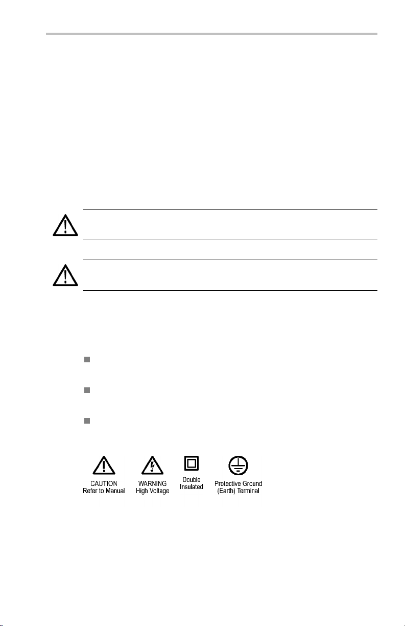
Symbols and Terms on the Product
These terms may appear on the product:
DANGER indicates an injury hazard immediately accessible as you
read the marking.
WARNING indicates an injury hazard not immediately accessible
as you read the marking.
CAUTION indicates a hazard to property including the product.
The following symbol(s) may appear on the product:
P5200 Instruction Manual iii
Page 10

Service S afety Sum mary
Service Safety Summary
Only qualified personnel should p erform service procedures. Read
this Service Safety Summary and the General Safety Summary before
performing any service procedures.
Do Not Service Alone. Do not p
of this product unless another person capable of rendering first aid and
resuscitation is present.
Disconnect Power. To avoid electric shock, switch off the instrument
power, then disconnect the power cord from the mains power.
Use Care W hen S ervici
may exist in this product. Disconnect power, remove battery (if
applicable), and disconnect test leads b efore removing p rotective panels,
soldering, or rep
To avoid electric shock , do not touch exposed co nnection s.
ng With Power On.
lacing components.
erform internal service or adjustments
Dangerous voltages or currents
iv P5200 Instruction Manual
Page 11

Compliance Information
This sectio n lists the EMC (ele
environmental standards with which the instrument complies.
EMC Compliance
EC Declaration of Conformity – EMC
Meets intent of Directive 2004/108/EC for Electromagnetic
Compatibility. Compliance was demon strated to the following
specifications as listed in the Official Journal of the European
Communities:
EN 61326-1:2006, EN 61326-2 -1:20 06. EMC requirements for electrical
equipment for measurement, control, and laboratory use.
CISPR 11:2003. Radiated and conducted emissions, Group 1,
Class A
IEC 61000-4-2:2001. Electrostatic discharge immunity
IEC 61000-4-3:2002. RF electromagnetic field immunity
IEC 61000-4-4:2004. Electrical fast transient / burst immunity
IEC 61000-4-5:2001. Pow er line surge immunity
IEC 61000-4-6:2003 . Conducted RF immunity
IEC 61000-4-11:2004. Voltage dips and interruptions immunity
ctromagnetic compliance), safety, and
123
4
EN 61000-3-2:2006. AC power line harmonic emissions
EN 61000-3-3:1995. Voltage changes, fluctuations, and flicker
European Contact.
Tektronix UK, Ltd.
Western Peninsula
West e rn Road
Bracknell, RG12 1RF
United Kingdom
P5200 Instruction Manual v
Page 12

Compliance Information
1
This product is intended for use in nonresidential areas only. Use in residential areas
may cause electromagnetic interference.
2
Emissions which exceed the levels required by this standard may occur when this
equipment is connected to a test o
3
To ensure compliance with the EMC standards listed here, high quality shielded interface
cables should be used.
4
Performance Criterion C applied at the 70%/25 cycle Voltage-Dip and the 0%/250 cycle
Voltage-Interruption test levels (IEC 61000-4-11).
Australia / New Zealand D eclaration of Conformity – EMC
Complies with the EMC provision of the Radiocommunications Act per
the following standard, in accordance with A CMA:
CISPR 11:2003. Radiated and Conducted Emissions, Group
1, Class A, in accordance with EN 61326-1:2006 and
EN 61326-2-1:2006.
bject.
vi P5200 Instruction Manual
Page 13

Safety Compliance
EC Declaration of Conformity – Low Voltage
Compliance was demonstrated to the following specification as listed in
the Official Journal of the European Communities:
Low Voltage Directive 73/23/EEC, as amended by 93/68/EEC:
EN 61010-1/A2:1995 – Safety requirements for electrical
equipment for measurement, control, and laboratory use
EN 6 101 0-2 -0 31:199 4 – Particular requirements for hand-held
probe assemblies for electrical measurement and test equipment.
U.S. Nationally Recognized Testing Laboratory Listing
UL3111-1 – Standard for electrical measuring and test equipment.
IEC 10106-2-031 – Particular requirements for hand-held probe
assemblies for electrical
Canadian Certification
CAN/CSA-C22.2 No. 1010.1-92 and CAN / CSA-C22.2 No.
1010.2.031-94 – Safety requirements for electrical equipment for
measurement, control, and laboratory use
Compliance Information
measurement and test
Installation (Overvoltage) Category Descriptions
Terminals on this product may have different installation (overvoltage)
category designations. The installation categories are:
CAT III Distribu tio n-level ma
Equipment at this level is typically in a fixed industrial location.
CAT II Local-level mains (wall sockets). Equipment at this
level in cludes appliances, portable too ls, and similar prod ucts.
Equipment is usually cord-connected.
CAT I Secondary (signal level) or battery-oper ated circuits of
electronic equipment.
ins (usually perm anently connected).
Pollution Degree
Pollution Degree 2. Do not operate in environments where conductive
pollutants may be present.
P5200 Instruction Manual vii
Page 14

Compliance Information
Radiated and Conducted Emissions
FCC Code 47 CFR. Part 15, Subpart B, Class A
VFG 0243 Enclosure: EN 5502 Class B limits for radiated emissions
AC Mains: EN 55022 Class B limits for conducted emissions and EN
60555-2 AC power harmonic emissions
To ensure compliance with the above requirements, only high quality
shielded inter face cables should be attached to this instrument. High
quality cables have a reliable, continuous outer shield (braid and foil)
that has low im pedan c e connections to sh ield ed connector housings at
both ends. The following cables m eet this criteria:
GPIB: Tektronix part num bers 012-0991-00, -01, -02 , -03
RS-232: Tektronix part number 012-1380-00
Printer: Tektronix part number 012-1250-00
Immunity, Enclosure, Radio Frequency Electromagnetic Field
IEC 801–3 Tested with TDS460 set to 50 mV/D iv vertically and
500 μs/ Div horizontally
Immunity, Enclosure, Electrostatic Discharge (ESD)
8 kV, IEC 801–2
Immunity, Fast Transients, Common Mode
IEC 801–4
Immunity, AC Power Line Transients
IEC 801–5
viii P5200 Instruction M an ual
Page 15

Environmental Considerations
This section provides information abou t the environmental impact of
the product.
Product End-of-Life Handling
Observe the following guidelines when recycling an instrument or
component:
Equipment Recycling. Production of this equipment required the
extraction and use of natural resources. The equipment may contain
substances that could b
if improperly handled at the product’s end of life. In order to avoid
release of such substances into the environment and to reduce the use
of natural resources
appropriate system that will ensure that most of the materials are reused
or recycled appropriately.
e harmful to the environment or human health
, w e encourage you to recycle this produ ct in an
Compliance Information
This symbol indica
applicable Europ
Directives 2002
electronic equi
about recyclin
the Tektronix
tes that this product complies with the
ean Union requirements according to
/96/EC and 2006/66/EC on waste electrical and
pment (WEEE) and batteries. For information
g options, check the Support/Service section of
Web site (www.tektronix.com).
Restriction of Hazardous Substances
This product has been classified as Monitoring and Control equipment,
and is outside the scope of the 2002/95/EC RoHS Directive.
P5200 Instruction Manual ix
Page 16

Compliance Information
x P5200 Instruction Manual
Page 17

Features and Accessories
The P5200 High Voltage Differential Probe provides a safe means of
measuring circuits with floating potentials up to 1,000 V
earth ground and up to 1,300 V (DC + peak AC) differential. This probe
must be connected to an oscilloscope or other measurement instrument
in which t he input BN C connector is at ground potential. The probe is a
safe alternative to the extremely dangerous practice of disconnecting
the oscilloscope ground to achieve a floating measurement.
The P5200 probe allows clear and accurate m easurements of high-speed
transitions and pro vid e s excellent common-mode rejection of noisy
signals. Both inputs have high impedance and low capacitance. Because
of these features, the probe can safely measure the fast voltage transients
in switching power devices such as IGBTs, power MOSFETs, thyristors,
GTOs, and bipolar transistors with out damaging these devices.
Other ap plications for the P5200 probe include testing hig h-voltage
motor control circuits and line connected circuits in switch-mode power
supplies.
WARNING. To avoid an electric shock, do not use the P5200 High
Voltage Differential Probe with oscilloscopes that have floating inputs
(isolated inputs), su ch as the Tektronix TPS2000 series oscilloscopes and
THS700 series oscillosco pes. The P5200 High Voltage Differential Probe
requires an oscilloscope or other measurement instrument with a grounded
input.
CAT II from
RMS
WARNING. To avoid RF burns, d o not handle the probe while the input
leads are connected to circuits above the voltage and frequency limits
specified. (See page 9, Safety limits.) Use on ly probe accessories that are
rated for the application.
CAUTION. Do not use the P5200 H igh Voltage Differential Probe above
1,000 V
AC) between the leads.
CAT I I from ground on either input or ± 1,300 V (DC + peak
RMS
P5200 Instruction Manual 1
Page 18
Features and Accessories
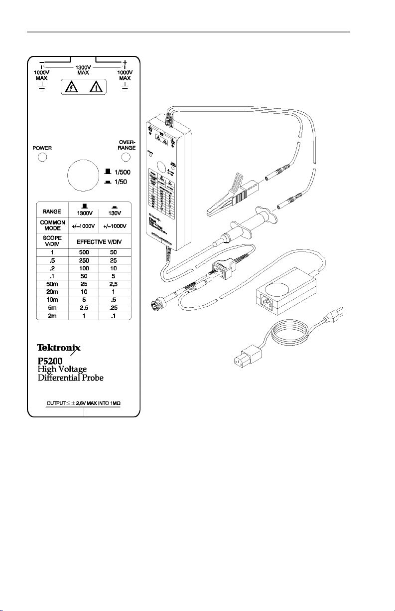
Figure 1: P5200 High Voltage Differential Probe
2 P5200 Instruction Manual
Page 19

Features and A ccessories
The P5200 has several features and accessories that make probing and
measurement a simpler task. Take a moment to familiarize yourself
with these items and their uses.
Power Indicator. The power indicator lights green
to show that power from the AC adapter is present.
Overrange Indicator. The overrange indicator
lights red if the voltage of the input signal exceeds
the linear range of the range setting. When this
happens, the signal on the probe output does not
accurately re present the signal on the probe input.
Range Button. In the raised position the
range button s ets the attenu ation to 1/500. In
the lowered position the range button sets the
attenuation to 1/50.
Use the 1/ 500 position for connections above
130 V up to a maximum of 1,300 V differential.
Use the 1/50 position for better signal resolution
on connections below 130 V (DC + peak AC).
Both range settings are rated for a maximum of
1,000 V
CAT II common mode.
RMS
Scale Conversion Chart. The chart lists the
effective volts per division for the 1/500 and 1/50
range settings a nd scale factors of 2 mV to 1 V on
the measurement instrument.
The effective volts per division is the a ttenua tion
factor of 500 or 50 multiplied by the scale factor
of the measurement instrument. For example,
with the range set to 1/500 and the measurement
instrument sensitivity set to 0.5 volts/division, the
effective volts per division equals 500× 0.5 or
250 V.
Differential Inputs. The inputs accept a maximum
of 1,000 V
CAT II between either input and
RMS
ground and a maximum difference of 1,300 V
(DC + peak AC) between the inputs. T hese input
ratings are valid for both range settings.
P5200 Instruction Manual 3
Page 20

Features and Accessories
Input Leads. The input leads of the differential
probe connect to the crocodile clips and plunger
probes that come with the probe. The connectors
are double insulated for safety.
NOTE. Use only the accessories provided with
the P5200 probe.
Plunger Probes. The plunger probes have long
probe sleeves with retracting hooks. These
probes connect safely to recessed test points that
are otherwise difficult to reac h. The connectors
are double insulated for safety.
Crocodile Clips. The large insulated clips
connect easily to large bolts or bus bars. The
connectors are double insulated for safety.
Output Lead. The BNC output connection to
the oscilloscope is calibrated to drive a high
impedance (1 MΩ) load.
Adapter Jack. The power supply jack on the
probe output connects to the 9 VDC p lug of the
AC adapter.
AC Adapter. The adapter converts AC line
voltage to 9 VDC for the probe power supply.
NOTE. The AC adapter that accompa nies the
P5200 probe is the only adapter specified for this
probe. Using any other adapter voids the product
warranty and may also produce electroma gnetic
interference. Adapters for the line voltages of
other countries are also available. Refer to the
Replaceable Parts section. (See page 29 .)
4 P5200 Instruction Manual
Page 21

Getting Started
To safely install and function
Differential Probe, follow the procedures in this section.
Installation
Install the P5200 probe as follows:
1. Connect the output of the
2. Connect the AC adapter to the jack located on the output lead of
3. Connect the AC adapter to the proper line voltage. The green power
4. Adjust the vertical offset (or position) of the measurement
5. Select the proper range setting. For higher resolution and less noise
6. Set the volts
ally check the P5200 High Voltage
probe to the BNC input of the oscilloscope
or other measurement instrument. The measurement instrument
input must have a ground reference.
the probe.
LED o n the probe should light.
instrument input.
when m easuri ng signals below 130 V, swit ch the attenuation to
1/50. If the ov
may not be accurate. Use the 1/500 setting instead.
the range indicated in the table on the front panel of the probe.
errange indicator lights or flashes, the output signal
per division setting on the measurement instrument to
WARNING. To avo id electrical shock, observe proper safety precautions
when working with voltages above 60 VDC or 30 VAC
levels pose a shock hazard. Make sure that the test leads are in good
condition. Use only the accessories supplied with the P5200 probe.
7. Using the appropriate probe accessories, connect the inputs of the
probe to the voltage source.
P5200 Instruction Manual 5
. These voltage
RMS
Page 22

Getting Started
CAUTION. To avoid damaging the input circuitry of the P5200 probe, do
not apply a voltage that is in excess of 1,000 V
input and ground or more than 1,300 V (DC + peak AC) between the two
inputs. This voltage rating applies to both 1/50 and 1/500 s ettings.
Functional Check
To make a sim ple functional check of the P5200 probe, select a source
that supplies AC line voltage and use the following procedure. This
procedure verifies a majority of the circuitry within the probe. For a
complete p erf or man ce verification, refer to Performance Verification
section. (See page 21.)
1. Use the installation procedure to connect the output of the P5200
probe to a measurement instrument. (See page 5, Installati on.)
2. Connect the inputs, set the range, and perform the check as each
line of the following table indicates.
Table 1: Functional check
CAT II between either
RMS
Input 1
(+ or –)
Hot
Hot
Hot
Input 2
(– or +)
Ground or
Neutral
Ground or
Neutral
Hot (same
connection)
Mode Range
Setting
Differential 1/500 (out)
Differential 1/50 (in) Overrange
Common
Mode
1/50 or 1/500
This completes the functional check procedure.
Check
Measurement
instrument
displays or
indicates the
line voltage
indicator
lights if the
input is
>130 Vp
No signal
6 P5200 Instruction Manual
Page 23

Operating Basics
To help you us e the P5200 Hig h Vo
effectively, this section provides important information about safety
limits, operating characteristics, and probing techniques.
WARNING. Due to the inherent hazards associated with taking high-voltage
measurements, the product is intende d for use by qualified personnel who
have had the training to make these types of measurements. Read and
follow the precautions specified in this manual.
Before you make any oscilloscope measurement, observe all safety
precautions described in the user and service manuals for the equipment
you are working on. Some general rules about using and servicing
electrical equipment are worth repeating here.
Observe the safety in stru ctio n symbols for t he equipment you are
working on.
Consult the instruction or service manuals for the equipment you
are working on.
Do not operate or service an electrical device in an explosive
atmosphere.
Avoid personal injury by never touching exposed connections or
components in the circuit-under-test when the power is on.
ltage Differential Probe safely and
Operating the Probe Safely
Before connecting the inputs of the probe to a circu it, read the safety
information in this section and attach the appropriate accessories to
the input connectors of the probe.
P5200 Instruction Manual 7
Page 24
Operating Basics
Minimizing Risk of RF Burn (probe leads)
WARNING. To avoid personal injury, do not handle the probe leads when
the leads are connected to a source that is above the voltage and frequency
limits. (See page 9, Safety limits.) The area above these limits poses a
risk of radio frequency (RF) burns.
If you need to use the p ro be within the risk area for RF burn, power off
the source before connec
Maximum Input Limits
CAUTION. To avoid damaging the input circuitry of the P5200 probe, do
not apply a voltage that is more than 1,000 V
input and ground or more than 1,300 V (DC + peak AC) between the two
inputs. Above 3 MHz, the voltage limit decreases as frequency increases.
(See page 9, Safety limits.) The input limit applies to both the 50X and
500X setting s.
ting or disconnecting the probe leads.
CAT II between either
RMS
8 P5200 Instruction Manual
Page 25

Operating Basics
Safety limits. This graph shows the voltage between either input a n d
earth ground.
1. Category II maximum voltage limit
2. RF burn risk a
rea (shaded)
3. Voltage derating with frequency
P5200 Instruction Manual 9
Page 26

Operating Basics
Operating Characteristics and Probing Techniques
This section explains the operating characteristics of the P5200 probe
along with techniques you can use to maximize t he performance of
the probe.
Operating L imits
The P5200 probe has two operating ranges that you select with the
ATTENUATION button on the front panel:
Select the 50X range for inputs o f 0 V to 130 V (DC + peak AC).
Select the 500X range fo r inputs of 130 V to 1300 V
(DC + peak AC).
Both ranges are rated for the maximum input limits, but you can obtain a
useful measurement only if the voltage you apply is within the specified
limits of the operating range.
Overrange Detection
Differential voltage outside the operating ran ge will overdrive the
circuitry of the probe and distort the output signal. When this
differential overrange occurs, the probe detects the condition and lights
the overrange indicator. With the Audible Overrange ON, the probe
will also emit an audible alarm.
Common-mode voltage greater than 1,000 V
can distort the output
RMS
signal, but the probe will not indicate an overrange condition.
Common-Mode Rejection
The comm on-mode rejection ratio (CMRR) is the specified ability of
P5200 High Voltage Differential Probe to reject signals th at are common
to both inputs. More precisely, C MRR is t he ratio of the differential gain
to the common-mode gain. The higher the ratio, the greater the ability
of probe to reject common-mode signals. For exact specifications, see
the Specifications section. (See Table 3 on page 16.)
Common mode rejection decreases as the input frequency increases.
The following Figure is a plot of typical CMRR of the probe versus
input frequency. For example, if you apply a 60 Hz line voltage of
500 V
80 dB (typical) and the signal appears as only a 50 mV
oscilloscope screen.
10 P5200 Instruction Manual
to both i npu t leads of the probe, the probe rejects the signal by
P-P
signal on the
P-P
Page 27

Operating Basics
Figure 2: Input impedance vs. frequency
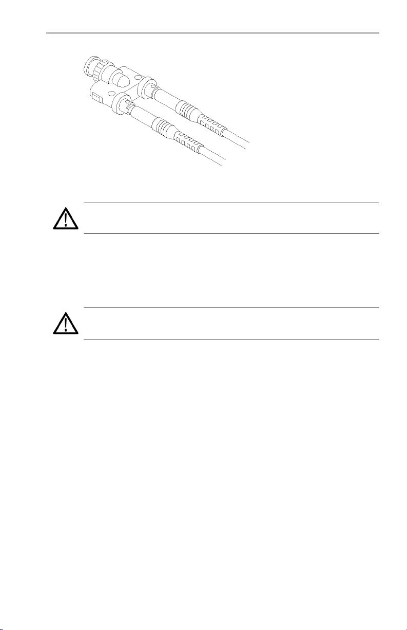
To ma xim ize the rejection of common-mode signals, twist the input
leads together and do not use the extension leads. (See Figure 3.)
Twisting the Input Leads
Twisting the input leads helps to cancel noise that is induced into the
input leads, and t o improve the high frequency response o f the inputs.
For the best response possible, do not use the exten sion leads.
P5200 Instruction Manual 11
Page 28

Operating Basics
Figure 3: Twisting the inp ut leads
Extension Leads
The extension leads allow you to reach widely spaced connection
points. Connect the extension leads to the input leads using the adapters
provided. Be sure to use both extension leads so that the input leads
are the same length.
The extension leads, however, do affect the high-frequency performance
of the probe. With longer lead length, differential noise induced into
the input leads is greater. Also, because of the added inductance of
the leads, voltage measurements at frequencies above approximately
10 MHz may not be as precise. The following figure shows the effect
on HF transient response with (left waveform) and withou t (righ t
waveform). ( See Figure 4 on page 13.)
The extension leads do not affect the performance of the probe when
bandwidth is set to 5 MHz.
12 P5200 Instruction Manual
Page 29

Operating Basics
Figure 4: HF transient response with (left) and without (right) extension leads
Probe Loading
When you touch your probe tip to a circuit element, you are introducing
a new resistance, ca
Frequency and impedance of the source determine how much the probe
loads the circuit t
starts to increase beyond 1 kHz, the input impedance of the probe begins
to decrease. The lower the impedance of the probe relative to that of the
source, the more
pacitance, and inductance into the circuit.
hat you are measuring. As the frequency of the source
the probe loads the circuit under test.
The probe has virtually no loading effect on sources with relatively
low impedance
P5200 Instruction Manual 13
and low frequency.
Page 30

Operating Basics
14 P5200 Instruction Manual
Page 31
Specifications
The specifications in the follo
wing tables apply to a P5200 High Voltage
Differential Probe installed on a Tektronix TDS460A oscilloscope.
When the probe is used with another oscilloscope, the oscilloscope must
have an input impedance 1 M Ω an
15 and 20 pF, and a bandwidth not less than 100 MHz.
The probe must have a warm-u
p period of at least 20 minutes and be in
an environment that does not exceed the limits. (See Table 2.)
Specifications for the P
5200 probe fall into three categories: warranty,
typical, and nominal characteristics.
WARNING. Special fixtures are required to examine specifications at the
maximum frequency and voltage levels and should be conducted only by
qualified Service Personnel. See the Service section for more details.
Warranted Characteristics
The warranted characteristics describe guaranteed performance within
tolerance limits or certain type-tested requirements. Warranted
characteristics that have check procedures in the Performance
Ver i ficatio n section are marked with the
Table 2: Warranted Electrical Characteristics
input capacitance range of between
symbol.
Characteristics
Rise Time
DC Common Mode
Rejection Ratio
(20-30°C, <70% RH)
Bandwidth
Maximum Operating Input
Voltage
Description
<14 ns in
>3000:1 at 500 VDC
DC to 25 MHz (-3dB) in 1/50 range setting
1/500 differential: ±1.3 kV (DC + peak AC)
1/500 common mode: ±1 kV
1/50 differential: ±130 V (DC + peak AC)
1/50 common mode: ±1 kV
1/50 range setting
RMS
RMS
CAT II
CAT II
P5200 Instruction Manual 15
Page 32

Specifications
Table 2: Warranted Electrical Characteristics (cont.)
Characteristics
Maximum Nondestructive
Input Voltage
Range Accuracy
Temperature
Humidity
Description
1/500 and 1/50 differential: ±1.3 kV (DC + peak AC)
1/500 and 1/50 common mode: ±1 kV
±3% at 20-30 °C, <70% RH after 20 minute warm up
Operating: 0 to 40 °C
Nonoperating: –30 to +70 °C
Operating: 25 to 85% RH, +25 to +35 ° C
Nonoperating: 25 to 85% RH, +25 to +60 °C
Typical Characteristics
The typical characteristics in the following tables describe ty pical , but
not guaranteed, performance.
Table 3: Typical Electrical Characteristics
Characteristics
Rise Time
Bandwidth
AC Common-Mode Rejection
Ratio(20-30°C,<70%RH)
Noise (m easured tangentially)
Input Impedance and
Capacitance
DC Output Drift ±0.5 mV/°C
Propagation Delay
Description
<14nsin1/500rangesetting
DC to 25 MHz (–3dB) in 1/500 range setting
60 Hz: >10,000:1, –80 dB
100 kHz: >300:1, –50 dB
1 MHz: >300:1, –50 dB
<4 mV
RMS
8MΩ, 3.5 pF between inputs
4MΩ, 7 pF between each input and groun d
20 nS
RMS
CAT II
Table 4: Typical Mechanical Characteristics
Characteristics
Dimensions, Case
Dimensions, Input Leads
Description
185 mm × 66 mm × 32 mm
(7.2 in × 2.6 in × 1.3 in)
46 cm (18 in)
16 P5200 Instruction Manual
Page 33

Table 4: Typical Mechanical Characteristics (cont.)
Specifications
Characteristics
Dimensions, Output Cable 1.8 m (6 ft)
Unit Weight (probe only) 315 g (11 oz)
Shipping Weight (with
accessories)
Description
1.42 kg (3 lb, 2 oz)
Nominal Characteristics
The Nominal characteristics shown in the following table describe
guaranteed traits, but the traits do not have tolerance limits.
Table 5: Nominal Electrical Characteristics
Characteristics
Input Type
Output Type Single-ended, load impedance must be greater than
Range Settings Switchable: 1/50 and 1/500
Description
Balanced
50 kΩ for stated accuracy
differential
P5200 Instruction Manual 17
Page 34

Specifications
18 P5200 Instruction Manual
Page 35

User Service
The P5200 High Voltage Differe
components or adjustments. The accessories are replaceable. (See
page 29, Replaceable Parts.)
For terms of the product warranty, refer to the front o f this manual.
Should the probe require replacement under terms of the warranty,
return the probe to a Tektro
information: name of pu rchaser, return address, n ame and ph one
number of a p erson that Tektronix may contact, date of purchase, and
a description of the def
of the manual.
Cleaning
To prevent dam age to probe ma terials, avoid using chemicals that
contain benzine, benzene, toluene, xylene, acetone, or similar solvents.
Do not immerse the probe or use abrasive cleaners.
Dirt may be remov
of detergent and water, or isopropy l alcohol.
ed with a s o ft cloth dampened with a mild solution
Packaging for Shipment
ntial Probe contains no user serviceable
nix service center. Include the following
ect. See Contacting Tektronix at the beginning
If the original packaging is unfit for use or not available, use the
following p ackaging guidelines:
1. Select a sturdy shipping carton that has in side dimensions at least
one inch greater than the probe dimensions.
2. Put the probe into a plastic bag or wrap to p rotect it from dampness.
3. Place th
material. Seal the carton with shipping tape.
P5200 Instruction Manual 19
e pro be into the box and stabilize it with light packing
Page 36

User Service
20 P5200 Instruction Manual
Page 37

Performance Verification
The following procedure verifi
of the P5200 High Voltage Differential Probe. The following table
itemizes the equipment required, provides an example or part number of
the equipment, and explains t
Table 6: List of equipm e nt required
Description Minimum
requirements
Test oscilloscope Bandwidth:
≥100 MHz Vertical
Accuracy: ≤1.5%
Standard
amplitude
generator
Leveled sine wave
generator
DC voltage source
Plunger probe
(2 required)
Modified BNC
adapter
BNC adapter BNC-female-to-dual
Amplitude
accuracy:
≤0.75%
Rise time
(standard
amplitude): ≤3ns
Use probes
Included in
accessory kit
BNC-male-to-dual
binding post
banana
es the warranted electrical characteristics
he purpose of the equipment.
Example or part
number
TDS460A or
TDS784A
Fluke/Wavetek
9100 with
oscilloscope
option 250
Accessory kit
020-2106-00
103-0035-00 Interconnection
103-0090-00 Interconnection
Purpose
Display probe
output
Check probe
attenuation,
bandwidth,
common-mode
rejection ratio
Connection to
binding post
between probe
and generator.
(See Figure 5 on
page 22.)
between probe
and generator
P5200 Instruction Manual 21
Page 38

Performance Verification
Table 6: List of equipment required (cont.)
Description Minimum
requirements
Coaxial cables
(2 required)
Termination
36 in (0.9144 m),
precision 50 Ω
50 Ω precision
feed through
Example or part
number
012-0482-00 Interconnection
011-0049-01 Int erconne ction
Construction of Modified BNC Adapter
Construct the modified BNC Adapter from a BNC-male-to-dual binding
post adapter, Tektronix part number 103-0035-00. (See Figure 5.)
Purpose
between
oscilloscope and
generator
between probe
and generator
during rise time
measurements
Figure 5: BNC-male-to-dual binding post adapter
To expose the posts that you will connect the P5200 High-Voltage
Differential probe leads to, remove the black and red plastic post covers
of the BNC-male-to-dual adapter. Use a pair of pliers and a vise to
remove the plastic covers. ( See Figure 6.)
22 P5200 Instruction Manual
Page 39

Setup
Performance Verification
Figure 6: Removing plastic covers from binding posts
WARNING. These procedures require the application of high voltage to
the inputs of the P5200 probe. Because this adapter has exposed metal
surfaces, only qualified personnel should perform any testing with voltage
levels exceeding 30 V rms. All pertinent safety rules and guidelines for
elevated voltage measurements should be followed and adhered to.
1. Connect the output of the probe to the Channel 3 of the test
oscillos
2. Connect the 9 VDC o utp ut plug of the AC adapter to the input jack
of the pr
voltage. The green power LED o n the probe should light.
3. Make a
Table 7 on page 28.)
P5200 Instruction Manual 23
cope. Let the probe warm up for 20 minutes.
obe, and then connect the AC adapter to the correct line
copy of the test record to tabulate the test results. (See
Page 40

Performance Verification
Amplitude Accuracy
1. Set the volts/division on channel 2 of the oscilloscope to 2 V.
Trigger on channel 2.
Select 1 MΩ impedance (if option exists on oscilloscope).
Connect coaxial cable between TRIG OUT of the generator
(rear of Wavetek 9100) and channel 2 of the oscilloscope.
2. Set the volts/divisio n on channel 1 of the oscilloscope to 20 mV.
3. Set the seconds/div t o 200 µs an d the acquisition mode to
average 32.
4. Connect the coaxial cable from SIG OUT of the generator (rear of
Wavetek 9100) to channel 1 of the oscilloscope.
5. Set the generator to 0.1 V and 1 kHz (AUX, square w ave, 1 MΩ
load). Enable the output.
6. Select the amplitude m easurem ent on the oscilloscope and record
the DC amplitude (~100 mV) of square wave. This measurement
is the just oscilloscope.
7. Disable the generator output. Disconnect the coaxial cable from
channel 1 of the oscilloscope and SIG OUT of the generator.
8. Connect the output of the probe to channel 1 of the oscilloscope.
9. Attach the Modified BNC adapter to the SIG OUT o f the generator.
10. Attach the differential probe input leads (without attachment
accessories) by sliding the banana plug of the leads onto the binding
posts of the Modifi ed BNC adapter. (See Figure 7.)
24 P5200 Instruction Manual
Page 41
Performance Verification
Figure 7: Slide probe leads onto the binding posts
WARNING. To reduce the risk of shock, ensure the generator output is
disabled before setting the volage above 30Vrµs.
11. Set the probe range button on the probe to1/
(out). Set the
500
generator for a 50 V and 1 kHz standard amplitude (AU X , Square
wave, 1 M Ω load ) output.
WARNING. Generator produces hazardous voltage. To avoid risk of shock,
do not touch exposed metal parts after the generator output is enabled.
12. Enable the output of the generator.
13. Record the DC amplitude of the square wave. Divide into the
amplitude of just the oscilloscope (refer to step 6) .
Verify that only
the probe gain accuracy is ±3%.
14. Set t he calibration generator for 5 V standard amp
wave) output. Set the probe range button on the probe to
15. Record the DC amplitude of the square wave. Divid
litude (squ are
1
/50(in).
e into the
amplitude of the oscilloscope (refer to step 6). Verify that only
the probe gain accuracy is ±3%.
16. Reduce the amplitude on the generator to minimum, then disable
the generator output and disconnect the setup.
P5200 Instruction Manual 25
Page 42

Performance Verification
Rise Time
1. Configure the fast rise output of the generator for a 50 Ω load
(AUX, rise, 50 Ω load, rising edge).
WARNING. Generator produces hazardous voltage. To avoid risk of shock,
do not touch exposed metal parts after the generator output is enabled.
2. Attach a 50 Ω terminator to the generator fast-rise output and attach
the modified BNC adapter to the terminator.
3. Set the generator for fast rise (<3 ns), 100 kHz, 1 V.
4. Set the oscilloscope vertical to 5 mV/div and the horizontal to
20 ns/div or 25 µs/div, depending on the slope).
5. Set the probe range to
6. Attach the differential pro b e input leads (without attachment
accessories) by sliding the banana plug of the leads onto the binding
posts metal sleeves on the modified B N C adapter. (See Figure 7 on
page 25.) Enable the output of the generator.
1
/50(push in ).
7. C heck that the rise time is <14 ns between the 10% and 90% points
of the displayed pulse.
8. Reduce the amplitude on the generator to minimum , then disable
the generator output and disconnect the setup.
26 P5200 Instruction Manual
Page 43

DC CMRR
1. Set the range of the probe to1/50.
2. Set the osci llo scope in put coup ling to DC, the vertical to 50 mV/div,
3. Attach the BNC-female-to-dual-banana adapter to the DC output of
4. Attach the plunger clamps on the differential probe input leads.
5. Twist the input leads together and connect both probe inputs to
WARNING. Generator produces hazardous voltage. To avoid risk of shock,
do not touch exposed metal parts after the generator output is enabled.
6. Set the output of the calibrator to 500 V, and enable the output.
Performance Verification
and the seconds/div to 200 µs. Center the trace on the display. Set
the acquisition mode to average 32.
the generator (front of Wavetek 9100). Attach the modifi ed BNC
adapter to the BNC-female-to-dual-banana adapter.
the positive terminal o f the modified BNC adapter. (See Figure 3
on page 12.)
7. Check that the trace on the oscilloscope shifts less than
3.33 divisions (167 mV) from center.
WARNING. To reduce risk of electrical shock , ensure the gen erator is
disabled before modifying/disconnecting test setup or connections since the
exposed metal may be at a hazardous potential. it is recommended that the
generator output amplitude be reduced to a minimum prior to disabling the
output.
8. Disable the calibrator output, and disconnect all test equipment.
This completes the performance verification procedure.
P5200 Instruction Manual 27
Page 44

Performance Verification
Table 7: P5200 test record
Probe Serial Number: ___________Certificate Number: __________
Temperature: ___________RH % : _ _________
Date of Calibration: _____________Technician: _____________
Performance test Minimum Results Maximum
Amplitude accuracy
Rise time
DC CMRR
–3% +3%
—
–167 mV +167 mV
<14 ns
28 P5200 Instruction Manual
Page 45

Replaceable Parts
This section contains a list of the replaceable modul es for the P5200
High Voltage Differential Probe. Use this list to identify and order
replacement parts.
Parts Ordering Information
Replacement parts are available through your local Tektronix field
office or representative.
Changes to Tektronix instruments are sometimes made to accommodate
improved components as they become available and to give you the
benefitofthelatestcircuitimprovements. Therefore, when ordering
parts, it is important to include the following inform ation in your order:
Part number
Instrument type or model number
Instrument serial number
Instrument modification number, if applicable
If you order a part that has been replaced with a different or improved
part, your local Tektronix field office or representative will contact you
concerning any change in part number.
Module Exchange
You may exchange your module for a remanufactured module. These
modules cost significantly less than n ew modules and meet the same
factory specifications. For more information about the module exchange
program, refer to Contacting Tektronix at the beginning of the manual.
P5200 Instruction Manual 29
Page 46

Replaceable Parts
Using the Replaceable Parts List
This section contains a list of the mechanical and/or electrical
components that are replaceable for the P5200 probe. Use this list to
identify and order replacement parts. The following table describes
each colum n in the parts list.
Table 8: Parts List Column Descriptions
Column Column Name
1
2 Tektronix Part Numbe
3
4
Figure & Index Number Items in this section are referenced by
Qty This indicates the quantity of parts used.
Name & Description An item name is separated from the
Abbreviations
Abbreviations conform to American National Standard ANSI
Y1.1-1972.
Description
figure and index numbers to the exploded
view illustrations that follow.
r
Use this part number w
replacement parts fr
description by a colon (:). Because of
space limitations, an item name may
sometimes appea r as incomplete. Use the
U.S. Federal Catalog handbook H6-1 for
further item name identification.
om Tektronix.
hen ordering
30 P5200 Instruction Manual
Page 47
Replaceable Parts
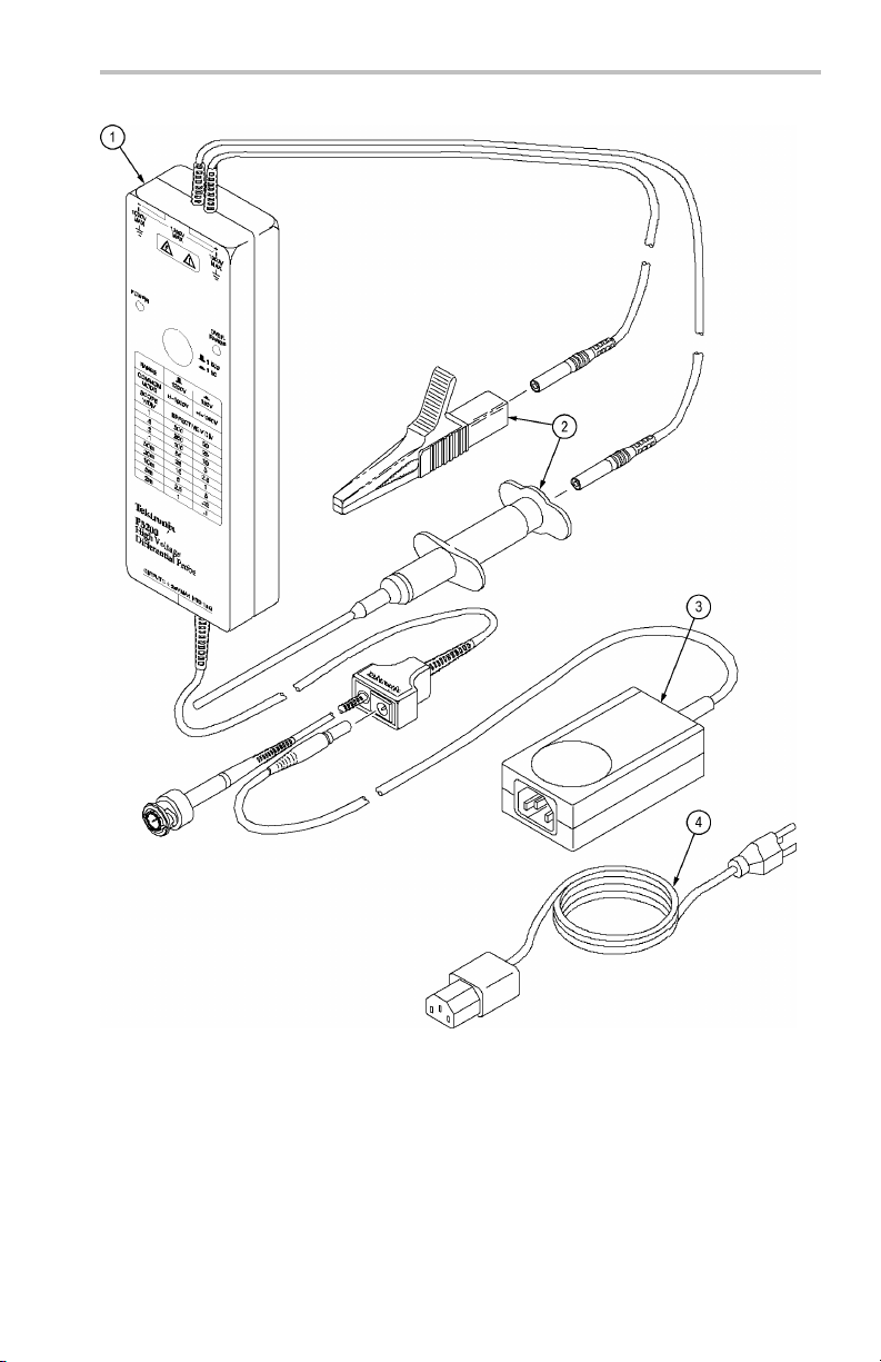
Figure 8: P5200 High Voltage Differential Probe and replaceable accessories
P5200 Instruction Manual 31
Page 48

Replaceable Parts
Fig.
&
Index
No.
8-1 119-4784-00 1
-2 020-2106-00 1
-3 119-7538-00 1
-4
—
Tek tronix
Part No. Qty 12345 Name & Description
161-0066-00 1
161-0066-09 1
161-0066-10 1
161-0154-00 1
161-0298-00 1
161-0304-00 1
070-9018-XX 1
PROBE,DIF ACT:POWER,1KV,25 MHZ
STANDARD ACCESSORIES
ACCESS PKG:(1) RED,(1) BLACK CROCODILE
CLIP& (1) RED, (1) BLACK INSULATED
PLUNGER CLAMP CLIP,COMPONENT KIT
POWER SUPPLY; 11.7W, EXTERNAL,
DESK-TOP; 9VDC, 1.3A OUT; 100-240 VAC
IN, 47-63 HZ, 2.1 MM BARREL CONNECTOR,
ENERGY STAR COM PLI ANT, SAFETY
CONTROLLED
CABLE ASSY PWR; 3,18 AWG, 250V/10A, 98.0
L, STR, IEC320, RCPT X NEMA 5-15P, US,
SAFETY CONTROLLED, (OPTION A0)
CABLE ASSY, PWR; 3,0.75MM SQ, 250V/10A,
99.0 L, STR IEC320, RCPT, EUROPEAN,
SAFETY CONTROLLED, (OPTION A1)
CABLE ASSY, PWR; 3,1.0 MM SQ, 250V/10A, 2.5
METER, STR, IEC320, RCPT X 13A, FUSED UK
PLUG (13A F U SE), UNITED KINGDOM, SAFETY
CONTROLLED, (OPTION A2)
CA ASSY, PWR; 3,1.0MM SQ,250V/10A, 2.5
METER, STR, IEC320, RCPT, SWISS, SAFETY
CONTROLLED, (OPTION A5)
CABLE ASS Y, PWR; 3,125V/7A, JAPAN, 98
LONG, STR, NEMA 5-15P PLUG X IEC320/C-13
RECEPTACLE, SAFETY CONTROLLED,
(OPTION A6)
CABLE ASSY, PWR; 3,1.0MM SQ, 250V/10A,2.5
METER, STR, IEC320, 3C CERTIFICATION,
RCPT, CHINA, SAFETY CONTROLLED,
(OPTION A10)
MANUAL, TECH:INSTRUCTIONS, P5200, ENG,
(OPTION L0)
32 P5200 Instruction Manual
 Loading...