

Tektronix P5100 User manual

Instructions
P5100
2500 V 250 MHz Oscilloscope Probe
070-8151-04
Warning
The servicing instructions are for use by qualified
personnel only. To avoid personal injury, do not
perform any servicing unless you are qualified to
do so. Refer to all safety summaries prior to
performing service.
www.tektronix.com

Copyright © Tektronix, Inc. All rights reserved.
Tektronix products are covered by U.S. and foreign patents, issued and
pending. Information in this publication supercedes that in all previously
published material. Specifications and price change privileges reserved.
Tektronix, Inc., 14200 SW Karl Braun Drive, Beaverton, OR 97077
TEKTRONIX and TEK are registered trademarks of Tektronix, Inc.

WARRANTY
Tektronix warrants that the products that it manufactures and sells will be free from defects
in materials and workmanship for a period of one (1) year from the date of shipment. If a
product proves defective during this warranty period, Tektronix, at its option, either will
repair the defective product without charge for parts and labor, or will provide a
replacement in exchange for the defective product.
In order to obtain service under this warranty, Customer must notify Tektronix of the
defect before the expiration of the warranty period and make suitable arrangements for the
performance of service. Customer shall be responsible for packaging and shipping the
defective product to the service center designated by T ektronix, with shipping charges
prepaid. Tektronix shall pay for the return of the product to Customer if the shipment is to
a location within the country in which the Tektronix service center is located. Customer
shall be responsible for paying all shipping charges, duties, taxes, and any other charges for
products returned to any other locations.
This warranty shall not apply to any defect, failure or damage caused by improper use or
improper or inadequate maintenance and care. Tektronix shall not be obligated to furnish
service under this warranty a) to repair damage resulting from attempts by personnel other
than Tektronix representatives to install, repair or service the product; b) to repair damage
resulting from improper use or connection to incompatible equipment; c) to repair any
damage or malfunction caused by the use of non-Tektronix supplies; or d) to service a
product that has been modified or integrated with other products when the effect of such
modification or integration increases the time or difficulty of servicing the product.
THIS WARRANTY IS GIVEN BY TEKTRONIX IN LIEU OF ANY OTHER
WARRANTIES, EXPRESS OR IMPLIED. TEKTRONIX AND ITS VENDORS
DISCLAIM ANY IMPLIED WARRANTIES OF MERCHANTABILITY OR
FITNESS FOR A PARTICULAR PURPOSE. TEKTRONIX’ RESPONSIBILITY
TO REPAIR OR REPLACE DEFECTIVE PRODUCTS IS THE SOLE AND
EXCLUSIVE REMEDY PROVIDED TO THE CUSTOMER FOR BREACH OF
THIS WARRANTY. TEKTRONIX AND ITS VENDORS WILL NOT BE LIABLE
FOR ANY INDIRECT, SPECIAL, INCIDENTAL, OR CONSEQUENTIAL
DAMAGES IRRESPECTIVE OF WHETHER TEKTRONIX OR THE VENDOR
HAS ADVANCE NOTICE OF THE POSSIBILITY OF SUCH DAMAGES.


Table of Contents
Contacting Tektronix ii................................
General Safety Summary iii............................
Features and Accessories 1.............................
Operating Basics 5...................................
Maximum Non-destructive Input Voltage 5.................
Grounding the Probe 5.................................
Ground Lead Length 5.................................
Adjustment Procedures 9..............................
Low Frequency (LF) Probe Compensation 9................
DC Gain and High Frequency (HF) Compensation 10.........
Gain Adjustment (DC Accuracy) 11....................
High-Frequency (HF) Adjustment 12....................
Performance Verification 15............................
DC Accuracy Check 16.................................
Bandwidth Check 17....................................
Maintenance 19.......................................
Cleaning 19...........................................
Preparation for Shipment 19..............................
Replacing Probe Parts 20................................
Specifications 23......................................
Replaceable Parts 29...................................
P5100 Instructions
i

Contacting Tektronix
Phone 1-800-833-9200*
Address Tektronix, Inc.
Department or name (if known)
14200 SW Karl Braun Drive
P.O. Box 500
Beaverton, OR 97077
USA
Web site www.tektronix.com
Sales
support
Service support
Technical
support
* This phone number i s toll free in North America. After office
hours, please leave a voice mail message.
Outside North America, contact a Tektronix sales office or
distributor; see the Tektronix web site for a list of offices.
1-800-833-9200, select option 1*
1-800-833-9200, select option 2*
Email: techsupport@tektronix.com
1-800-833-9200, select option 3*
1-503-627-2400
6:00 a.m. -- 5:00 p.m. Pacific time
ii
P5100 Instructions

General Safety Summary
Review the following safety precautions to avoid injury and prevent
damage to this product or any products connected to it. To avoid
potential hazards, use this product only as specified.
Only qualified personnel should perform service procedures.
To Avoid Fire or Personal Injury
Connect and Disconnect Properly. Connect the probe output to the
measurement instrument before connecting the probe to the circuit
under test. Disconnect the probe input and the probe ground from the
circuit under test before disconnecting the probe from the
measurement instrument.
Observe All Terminal Ratings. To avoid fire or shock hazard, observe all
ratings and markings on the product. Consult the product manual for
further ratings information before making connections to the product.
Do not apply a potential to any terminal that exceeds the maximum
rating of that terminal.
Connect the ground lead of the probe to earth ground only.
Avoid Exposed Circuitry. Do not touch exposed connections and
components when power is present.
Do Not Operate With Suspected Failures. If you suspect there is damage
to this product, have it inspected by qualified service personnel.
Do Not Operate in Wet/Damp Conditions.
Do Not Operate in an Explosive Atmosphere.
Keep Product Surfaces Clean and Dry.
P5100 Instructions
iii

General Safety Summary
Safety Terms and Symbols
Terms in This Manual. These terms may appear in this manual:
WARNING. Warning statements identify conditions or practices that
could result in injury or loss of life.
CAUTION. Caution statements identify conditions or practices that
could result in damage to this product or other property.
Terms on the Product. These terms may appear on the product:
DANGER indicates an injury hazard immediately accessible as you
read the marking.
WARNING indicates an injury hazard not immediately accessible as
you read the marking.
CAUTION indicates a hazard to property including the product.
Symbols on the Product. These symbols may appear on the product:
WARNING
Risk of Electric
Shock
Protective Ground
(Earth) Terminal
CAUTION
Refer to Manual
Double
Insulated
iv
P5100 Instructions
Features and Accessories
The P5100 is a 100X, 2500 V (DC + peak AC), 1000 V CAT III
oscilloscope probe that provides 250 MHz performance and is
certified to international safety standards. The P5100 probe is
compatible with all general purpose oscilloscopes and with Tektronix
oscilloscopes that automatically detect 100X probe attenuation and
display the correct scale readout. The P5100 probe is designed for
ground-referenced measurements only.
WARNING. Do not substitute accessories from other products for
those provided with the P5100. The accessories for the P5100 have
been safety tested, and the use of non-tested accessories may cause
injury or death.
To reduce risk of electric shock, keep your fingers behind the finger
guard on the probe body. Place your fingers in front of the finger
guard only when retracting the hook-tip accessory.
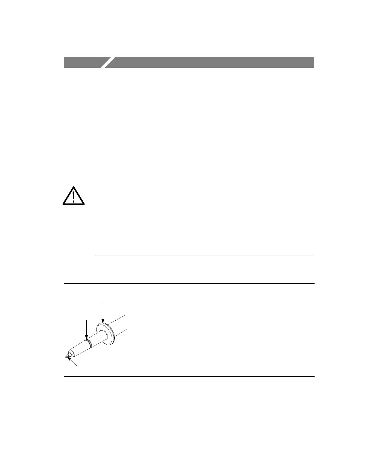
P5100 Features and Standard Accessories
Finger
Guard
Ground
Ring
6-32 Probe Tip
Probe Body -- The P5100 probe body is designed for personal
safety, ergonomic comfort, and signal fidelity.
The probe body ground ring connection allows a short ground
connection for optimal signal fidelity.
The probe tip is a 6--32 threaded post that accepts both standard and
optional accessories.
Keep the probe body and accessories clean and dry to reduce the risk
of shock due to surface conduction. Refer to page 19 for cleaning
instructions.
P5100 Instructions
1
Features and Accessories
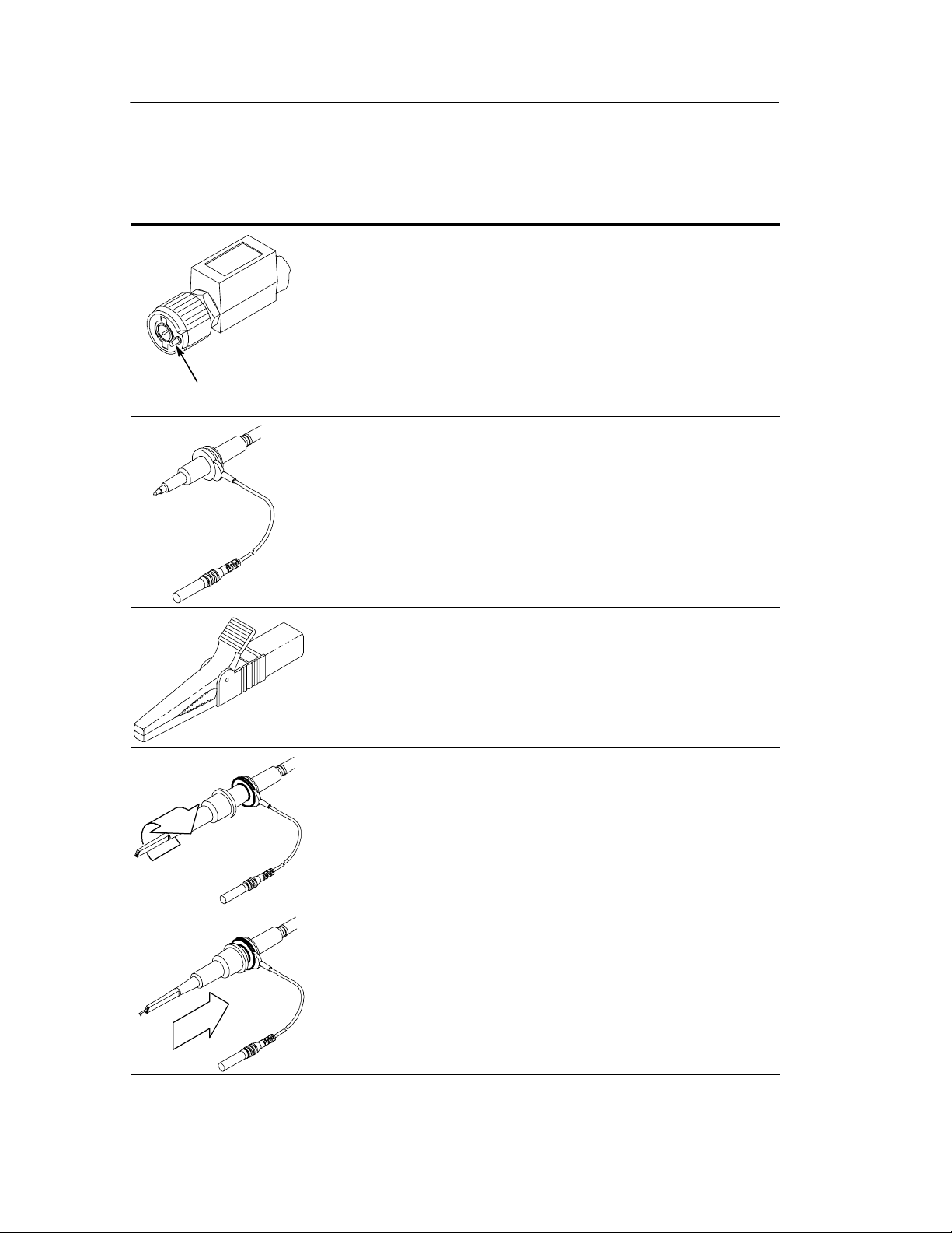
P5100 Features and Standard Accessories (Cont.)
Compensation Box -- The P5100 compensation box contains low-
and high-frequency compensation adjustments as well as a
gain adjustment.
The P5100 is compatible with Tektronix oscilloscopes that automatically detect and display the 100X attenuation factor of the probe.
(If you have an older instrument with a lit vernier indicator, the 10X
position will light. Multiply the reading by a factor of 10 to get the true
Readout Pin
value.)
Ground Leads -- The P5100 probe comes with a long and a short
ground lead. Both ground leads connect to a removable crocodile clip.
Attach the ground lead to the probe body by inserting the probe head
into the ground lead as shown.
The length of the ground lead directly impacts the fidelity of high-frequency signals. The longer the ground lead, the more the signal will
be distorted. For more information about the ground lead and signal
quality, go to page 5.
Crocodile Clip -- The large crocodile clip attaches to the insulated
banana connector on the long ground lead.
Small Hook Tip -- Use the small hook tip for making connections to
small conductors such as component leads.
Install the small hook tip by sliding it over the body of the probe and
screwing it onto the threaded probe tip.
To use the tip, hold the probe body and pull the tip shield back. Hook
the tip onto the circuit and release the shield. The hook tip will firmly
hold the conductor under test.
2
P5100 Instructions
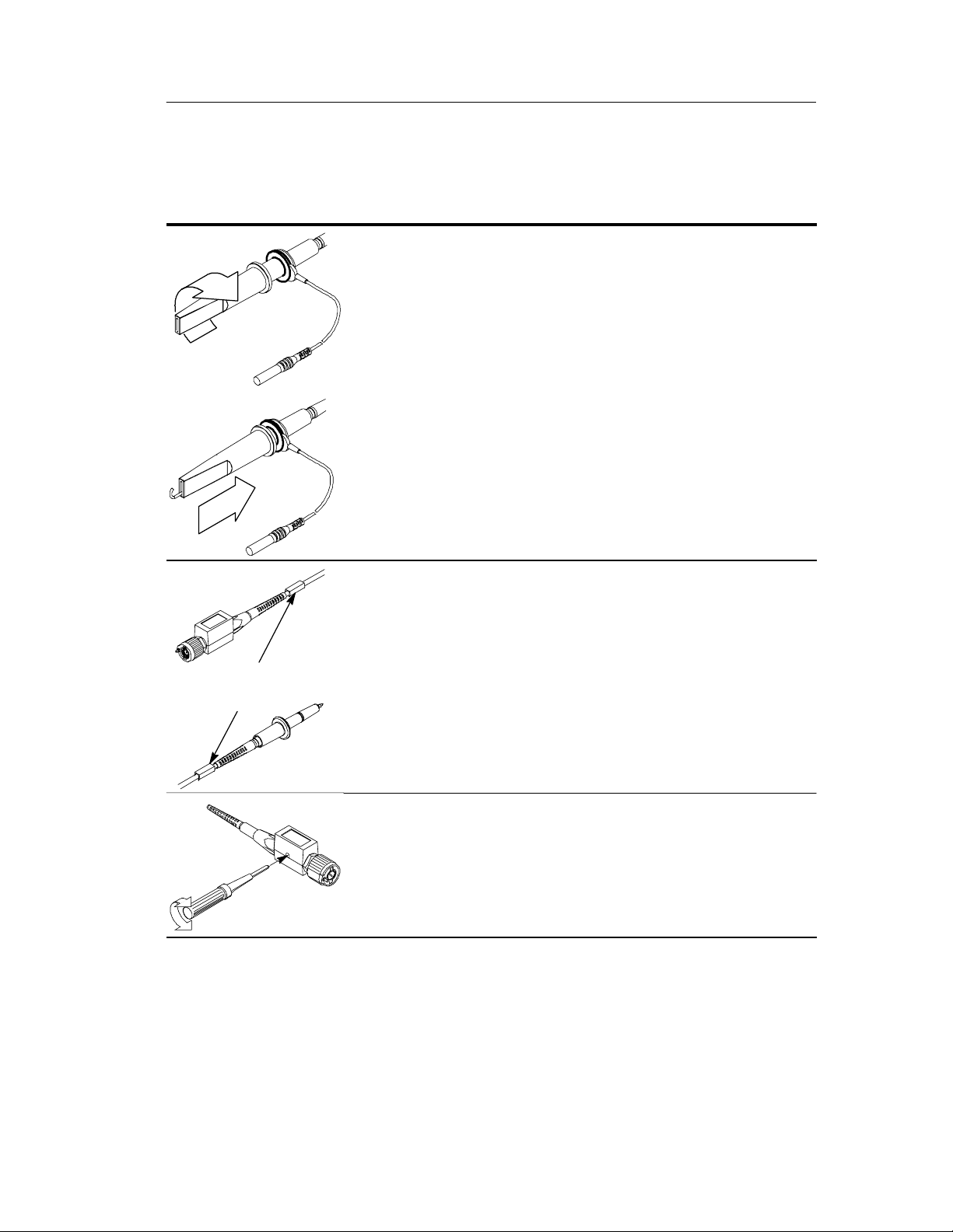
P5100 Features and Standard Accessories (Cont.)
Large Hook Tip -- Use the large hook tip when working with larger
components such as bolt terminals and buss bars typically found in
power distribution equipment.
Install the large hook tip by sliding it over the body of the probe and
screwing it onto the threaded probe tip.
To use the tip, hold the probe body and pull the tip shield back. Hook the
tip ontothe circuit and releasethe shield. The hooktip will firmly hold the
conductor under test.
Features and Accessories
Color Marker
Bands
Color Marker Bands -- The color marker bands help you identify
multiple probes in the circuit under test.
Clip the matching bands onto the cable at the probe head and compensation box to help identify probe channels at a glance.
Adjustment Tool -- Use the adjustment tool for probe compensation
adjustments. Do not use metallic or conductive tools while making
adjustments.
P5100 Instructions
3
Features and Accessories
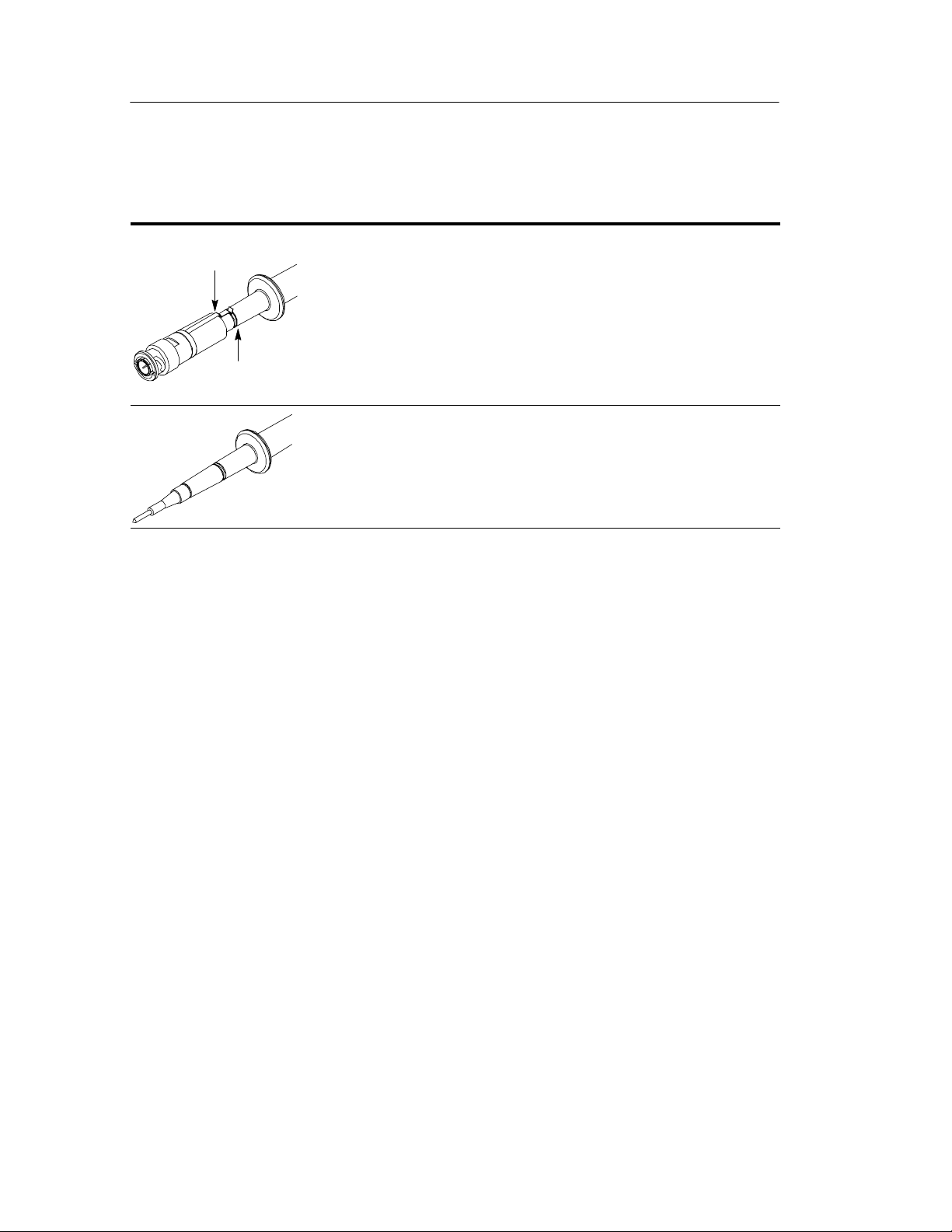
P5100 Optional Accessories
Ground
Clip
Ground
Ring
Probe Tip to BNC Adapter -- Use the probe tip to BNC adapter to
connect the probe directly to BNC connectors. The adapter is
recommended for use when verifying or adjusting the probe.
WARNING. The BNC adapter is rated to 500 V (DC + peak AC). Do
not attempt to use the adapter for high voltage testing.
Attach the adapter by pressing it onto the 6-32 probe tip and making
sure that the ground clip makes contact with the ground ring.
Rubber Spring Tip -- Use the rubber spring tip to connect the P5100
to larger test sockets located in equipment or on printed circuit boards.
Connect the rubber spring tip by screwing it onto the threaded
probe tip.
4
P5100 Instructions
 Loading...