

Page 1

Instructions
P3010
100 MHz 10X Passive Probe
With Readout
071-0466-00
Page 2

Copyright © Tektronix, Inc. All rights reserved.
Tektronix products are covered by U.S. and foreign patents, issued and
pending. Information in this publication supercedes that in all previously
published material. Specifications and price change privileges reserved.
Printed in the U.S.A.
Tektronix, Inc., P.O. Box 1000, Wilsonville, OR 97070–1000
TEKTRONIX and TEK are registered trademarks of Tektronix, Inc.
Page 3

General Safety Summary
Review the following safety precautions to avoid injury and prevent
damage to this product or any products connected to it. To avoid
potential hazards, use this product only as specified.
To Avoid Fire or Personal Injury
Observe Maximum Working Voltage. Do not use the P3010 probe above
300 V
Connect and Disconnect Properly. Connect the probe output to the
measurement instrument before connecting the probe to the circuit
under test. Disconnect the probe input and the probe ground from the
circuit under test before disconnecting the probe from the measurement instrument.
Do Not Elevate the Common Terminal. The common terminal is at
ground potential. Do not connect the common terminal to elevated
voltages.
, CAT II. Refer to the derating chart, Figure 2, on page 12.
RMS
Do Not Operate With Suspected Failures. If you suspect there is damage
to this product, have it inspected by qualified service personnel.
Do Not Operate in Wet/Damp Conditions.
Do Not Operate in an Explosive Atmosphere.
Keep Product Surfaces Clean and Dry.
Safety Terms and Symbols
Terms in This Manual. These terms may appear in this manual:
WARNING. Warning statements identify conditions or practices that
could result in injury or loss of life.
CAUTION. Caution statements identify conditions or practices that
could result in damage to this product or other property.
P3010 Passive Probe Instructions
1
Page 4
Features and Accessories
The P3010 probe is compatible with TDS3000 series 100 MHz
oscilloscopes. The probe is also compatible with Tektronix
oscilloscopes that automatically detect probe attenuation and adjust
the scale readout accordingly.
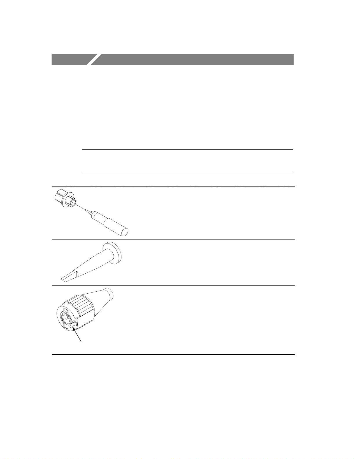
NOTE. Remove and discard the protective cover on the tip of the
probe before attempting to connect a probe tip accessory.
BNC-to-probe tip adapter. T o install the adapter,
push the wide end firmly into a BNC connector .
Then insert the probe tip firmly into the adapter.
Retractable hook tip. Use the retractable hook tip to
make hands-free measurements.
Readout Pin
NOTE.
twist the hook tip onto the probe tip before using.
Readout pin. The P3010 is compatible with Tektronix oscilloscopes that automatically detect and
display the attenuation factor of the probe.
For a solid connection, firmly push and
2
P3010 Passive Probe Instructions
Page 5
Features and Accessories
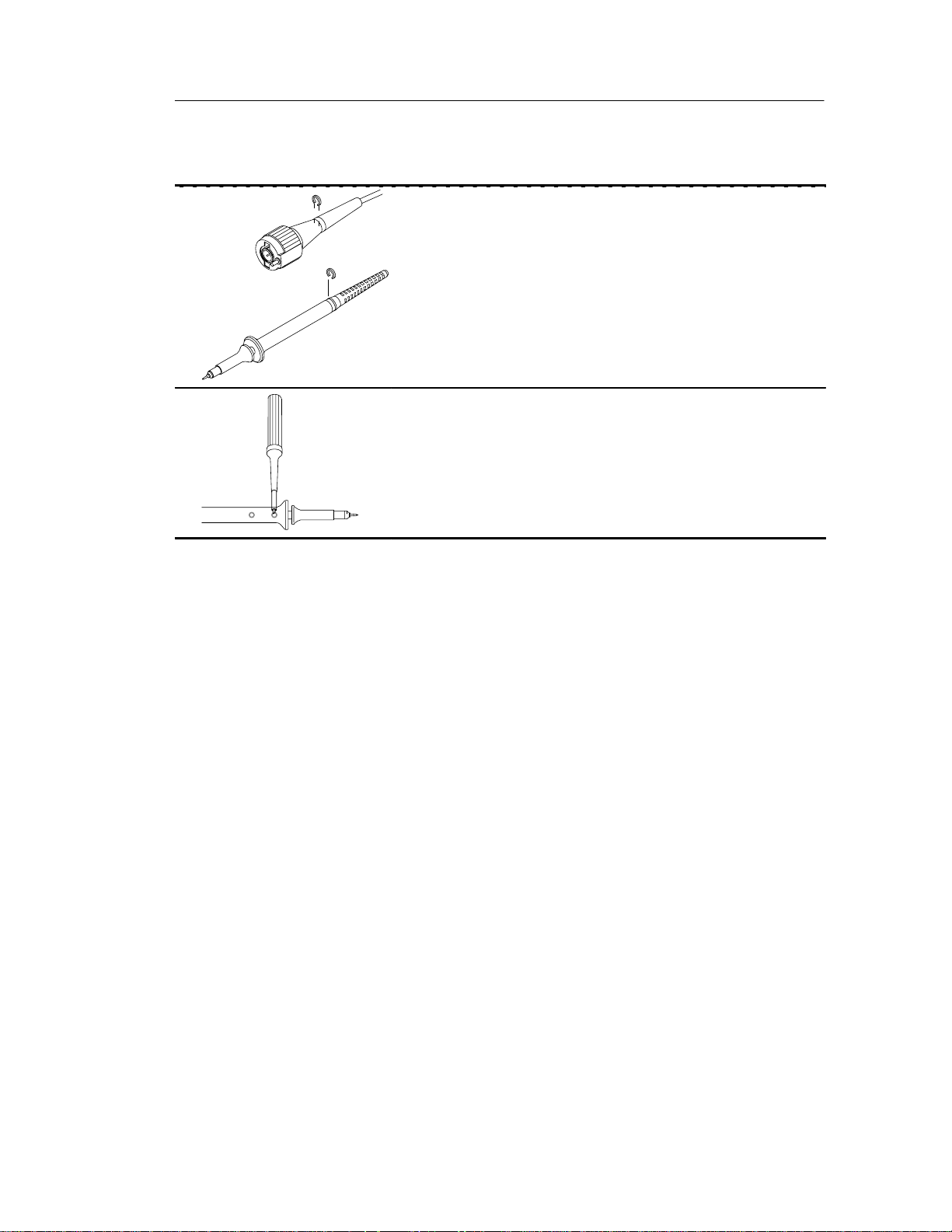
Marker rings. Attach the matching colored rings
onto the probe cable and tip as shown.
Adjustment tool. Use the adjustment tool for probe
compensation adjustments.
P3010 Passive Probe Instructions
3
Page 6
Features and Accessories
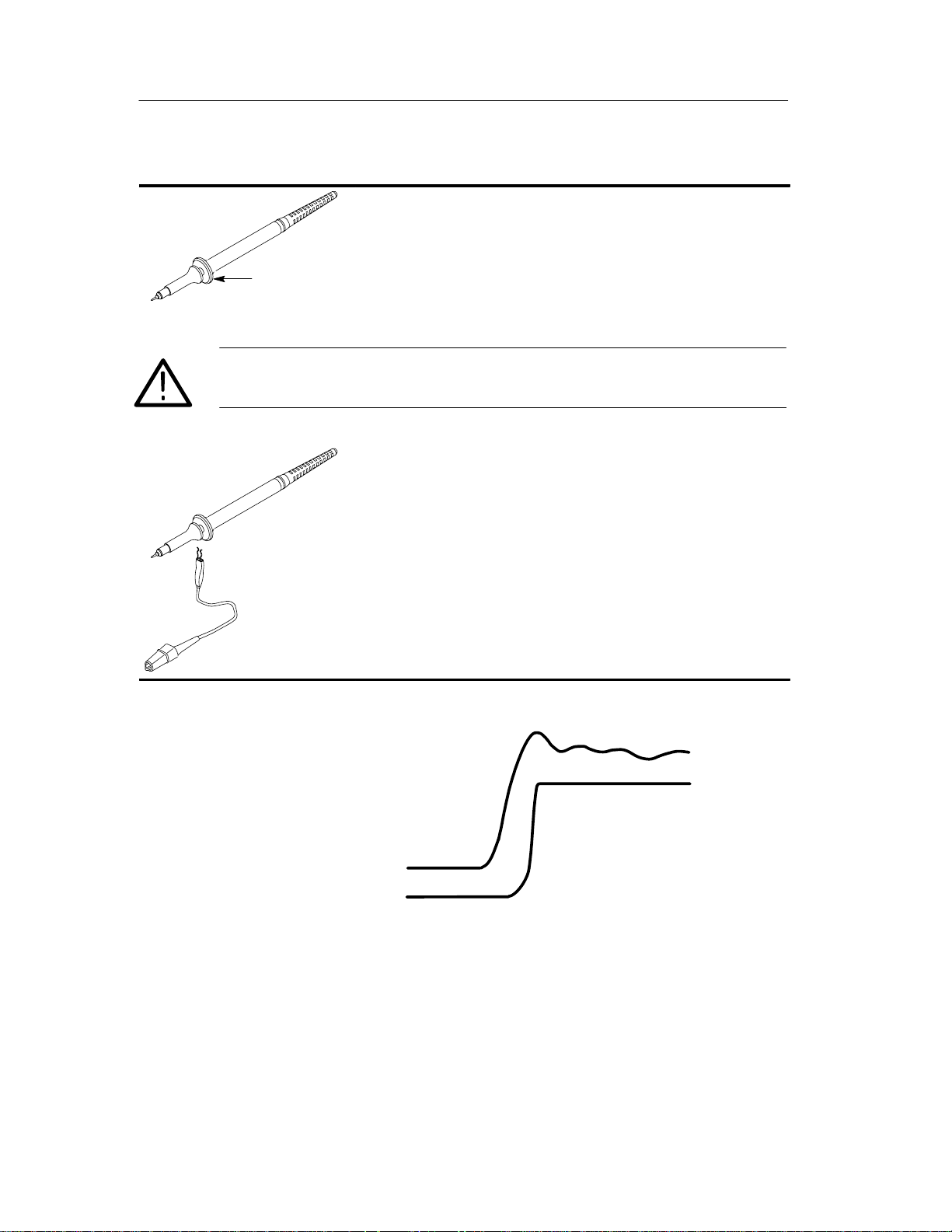
Guard
WARNING. To avoid electric shock when using the probe, keep
fingers behind the guard on the probe body.
Guard. The guard provides a finger barrier for
protection from electric shock.
Ground Lead. Use the alligator clip to attach the
probe to a ground reference.
Long Ground Lead
Short Ground Lead
To see the best signal, use the shortest possible ground lead and
signal path.
4
P3010 Passive Probe Instructions
Page 7

Maintenance
This section describes how to maintain the probe.
Low-Frequency Probe Compensation
Before taking any measurements using a probe, first check the
compensation of the probe and adjust it to match the channel inputs.
Most oscilloscopes have a square wave reference signal available at
a terminal on the front panel used to compensate the probe.
1. Connect the probe to the signal source to display a 1 kHz test
signal on your oscilloscope.
2. Adjust the LF trimmer on the probe so that the corners of the
square wave are square and the top is flat.
LF trimmer
1 kHz
P3010 Passive Probe Instructions
5
Page 8

Maintenance
High-Frequency Probe Compensation
The probe high-frequency compensation should seldom require
adjustment; however , your probe may require high-frequency
adjustment if any of the following are true:
H the probe has high-frequency aberrations
H the probe does not perform at the rated bandwidth
H you have installed the probe on an oscilloscope having an input
capacitance near the limits of the probe compensation range (See
Table 1.)
To perform the high-frequency compensation adjustment you will
need a signal source that has all of the following characteristics:
1 MHz
>1 V
p-p
H square-wave output at 1 MHz
H fast rise output with rise time less than 1 ns
H output properly terminated
tr<1 ns
90%
10%
6
P3010 Passive Probe Instructions
Page 9

Maintenance
1. Connect the probe to the signal source to display a 1 MHz test
signal on your oscilloscope. The display should be similar to that
shown in Figure 1(a).
2. Adjust the HF trimmer until the waveform is flat on top and has a
square leading edge.
10 ns
(a) Area Of Waveform Affected By
HF Adjustment
Figure 1: HF Compensation
Cleaning
To prevent damage to probe materials, avoid using chemicals that
contain benzine, benzene, toluene, xylene, acetone, or similar
solvents.
Do not immerse the probe or use abrasive cleaners.
Dirt may be removed with a soft cloth dampened with a mild
detergent and water solution, or isopropyl alcohol.
HF trimmer
(b) Location of HF Adjustment
P3010 Passive Probe Instructions
7
Page 10

Maintenance
Replacing Probe Parts
Other than accessories, only the probe tip is replaceable.
Replacement probe tips are available as optional accessories. Refer
to the replaceable parts list at the end of this manual for more
information.
To remove a tip assembly, firmly grasp the pointed tip with pliers
and withdraw the assembly from the barrel.
No tools are required to install a replacement tip. Insert a new probe
tip into the probe barrel as far as possible using finger pressure. If
necessary, seat the plastic portion of the tip against the probe barrel
by pressing the tip gently but firmly against a hard surface, such as a
wood block or table top.
8
P3010 Passive Probe Instructions
Page 11

Specifications
Table 1
lectrical Character
These characteristics apply to a P3010 probe installed on a
Tektronix TDS3000 series 100 MHz oscilloscope.
The instrument must have a warm-up period of at least 20 minutes
and be in an environment that does not exceed the limits described in
Table 2.
: E
Attenuation (system) 10X"2.5% at DC
Input Resistance (system), typical
Input Capacitance, typical 13.3 pF
Compensation Range, typical 10 pF to 15 pF
System Bandwidth (–3 dB) DC to 100 MHz
Maximum Working
Input Voltage
Rise time (system), typical 3.5 ns
Input impedance and phase, typical See Figure 3 on page 13
istics
10 MW
300 V
35%, pulse width < 100 msec)
150 V
pulse width < 100 msec)
See derating information in Figure 2 on page 12
, CAT I & II (500 V peak, duty factor <
RMS
, CAT III (250 V peak, duty factor < 35%,
RMS
P3010 Passive Probe Instructions
9
Page 12

Specifications
Table 2
cal an
ronmental Character
: Physi
Net Weight
(including accessories)
Cable Length 2 meters
Temperature Range
Operating
Nonoperating
Humidity
Altitude
1
T ektronix Standard 062-2847-00, class 3. Refer to MIL-T-28800E for class 3
1
Operating
Nonoperating
d Envi
1
istics
t320 g
–15° C to +55°C
–62° C to +85° C
95% to 97% Relative Humidity
(30°C to 55°C)
< 3000 meters
< 15240 meters
equipment.
10
P3010 Passive Probe Instructions
Page 13

T able 3: Certifications and compliances
Specifications
EC Declaration of
Conformity – Low
Voltage
Approvals UL3111-1 – Standard for electrical measuring and test equipment
Installation Category
Descriptions
Compliance was demonstrated to the following specification as
listed in the Official Journal of the European Communities:
Low Voltage Directive 73/23/EEC, as amended by 93/68/EEC:
EN 61010-1/A2:1995
Safety requirements for electrical equipment for
measurement, control, and laboratory use
EN 61010-2-031:1994
Particular requirements for hand-held probe assemblies for
electrical measurement and test equipment
IEC 61010-2-031 – Particular requirements for hand-held probe
assemblies for electrical measurement and test
CAN/CSA-C22.2 No. 1010.1-92 and CAN/CSA-C22.2 No.
1010.2.031-94 – Safety requirements for electrical equipment for
measurement, control, and laboratory use
Terminals on this product may have different installation category
designations. The installation categories are:
CAT III Distribution-level mains (usually permanently
connected). Equipment at this level is typically
in a fixed industrial location
CAT II Local-level mains (wall sockets). Equipment at
this level includes appliances, portable tools,
and similar products. Equipment is usually
cord-connected
CAT I Secondary (signal level) or battery operated
circuits of electronic equipment
Pollution Degree 2 Do not operate in environments where conductive pollutants may
be present.
P3010 Passive Probe Instructions
11
Page 14

Specifications
400V
300V
200V
Category I & II
Category III
10V
0
Frequency (Hz)
Voltage
(V
RMS
100V
)
Figure 2: Maximum Working Voltage Derating Curve (V
5M 50M
10M 100M1M
)
RMS
200M
12
P3010 Passive Probe Instructions
Page 15

Specifications
10 MW
1 MW
100 kW
10 kW
1 kW
+50°
+25°
0°
–25°
–50°
100 W
10 W
1 W
100 Hz
1 kHz 10 kHz 100 kHz 1 MHz
Impedance (W)
Phase (°)
Figure 3: Typical input impedance and phase
10 MHz
–75°
–100°
–125°
100 MHz
P3010 Passive Probe Instructions
13
Page 16

Replaceable Parts
2
1
5
3
7
4
Standard Accessories
8
6
9
Figure 4: P3010 replaceable parts
14
Optional Accessories
P3010 Passive Probe Instructions
Page 17

P3010 Passive Probe Instructions 15
Replaceable Parts List
Fig. &
index
number
4– ––––––––––– 1 PROBE,PASSIVE:P3010
Tektronix
part number
Serial no.
effective
Serial no.
discont’d
Qty Name & description Mfr. code Mfr. part number
STANDARD ACCESSORIES
020–2134–01 1 ACCESSORY KIT:MINIATURE SIZE
(Includes items 1, 3, 4, 5, & 6)
–1 013–0107–08 1 TIP,PROBE:MINIATURE/COMPACT SIZE TK2565 013–0107–08
–2 See Opt. Acc 1 CONTACT,ELEC:PROBE TIP W/INSULATOR ASSY
–3 196–3120–01 1 LEAD,ELECTRICAL:PROBE GND,6.0 L 80009 196–3120–01
–4 016–0633–00 1 MARKER SET,CA:2 EA VARIOUS COLORS 80009 016–0633–00
–5 See Opt. Acc. 1 SCREWDRIVER:ADJUSTMENT TOOL
–6 013–0277–00 1 ADAPTER,CONN:BNC TO MINIATURE PROBE TIP 24931 33A129–1
071–0466–00 1 MANUAL,TECH:INSTR, P3010, DP 80009 071–0466–00
OPTIONAL ACCESSORIES
–2 131–4997–01 1 CONTACT,ELEC:2 TIP–INSULATOR W/INFO CARD 80009 131–4997–01
–5 003–1433–01 1 SCREWDRIVER:ADJUSTMENT TOOL,PKG OF 5 80009 003–1433–01
–7 196–3120–21 1 LEAD,ELECTRICAL:PROBE GND,28.0 L 80009 196–3120–21
–8 196–3121–01 1 LEAD,ELECTRICAL:PROBE GND,12.0 L 80009 196–3121–01
–9 015–0201–07 1 TIP,PROBE:IC TEST,PKG OF 10 80009 015–0201–07
80009 020–2134–01
Replaceable Parts
Page 18

Manufacturers Cross Index
Mfr.
code
Manufacturer Address City, state, zip code
Replaceable Parts
P3010 Passive Probe Instructions16
24931 BERG ELECTRONICS INC BERG ELECTRONICS RF/COAXIAL DIV
2100 EARLYWOOD DR
PO BOX 547
80009 TEKTRONIX INC 14150 SW KARL BRAUN DR
PO BOX 500
TK2565 VISION PLASTICS INC 26000 SW PARKW AY CENTER DRIVE WILSONVILLE, OR 97070
FRANKLIN, IN 46131
BEAVER T ON, OR 97077–0001
Page 19

WARRANTY
T ektronix warrants that the products that it manufactures and sells will be free from defects
in materials and workmanship for a period of one (1) year from the date of shipment. If a
product proves defective during this warranty period, Tektronix, at its option, either will
repair the defective product without charge for parts and labor, or will provide a
replacement in exchange for the defective product.
In order to obtain service under this warranty, Customer must notify Tektronix of the
defect before the expiration of the warranty period and make suitable arrangements for the
performance of service. Customer shall be responsible for packaging and shipping the
defective product to the service center designated by Tektronix, with shipping charges
prepaid. T ektronix shall pay for the return of the product to Customer if the shipment is to
a location within the country in which the Tektronix service center is located. Customer
shall be responsible for paying all shipping charges, duties, taxes, and any other charges for
products returned to any other locations.
This warranty shall not apply to any defect, failure or damage caused by improper use or
improper or inadequate maintenance and care. Tektronix shall not be obligated to furnish
service under this warranty a) to repair damage resulting from attempts by personnel other
than Tektronix representatives to install, repair or service the product; b) to repair damage
resulting from improper use or connection to incompatible equipment; c) to repair any
damage or malfunction caused by the use of non-Tektronix supplies; or d) to service a
product that has been modified or integrated with other products when the effect of such
modification or integration increases the time or difficulty of servicing the product.
THIS WARRANTY IS GIVEN BY TEKTRONIX IN LIEU OF ANY OTHER
WARRANTIES, EXPRESS OR IMPLIED. TEKTRONIX AND ITS VENDORS
DISCLAIM ANY IMPLIED WARRANTIES OF MERCHANTABILITY OR
FITNESS FOR A PARTICULAR PURPOSE. TEKTRONIX’ RESPONSIBILITY
TO REPAIR OR REPLACE DEFECTIVE PRODUCTS IS THE SOLE AND
EXCLUSIVE REMEDY PROVIDED TO THE CUSTOMER FOR BREACH OF
THIS WARRANTY. TEKTRONIX AND ITS VENDORS WILL NOT BE LIABLE
FOR ANY INDIRECT, SPECIAL, INCIDENTAL, OR CONSEQUENTIAL
DAMAGES IRRESPECTIVE OF WHETHER TEKTRONIX OR THE VENDOR
HAS ADVANCE NOTICE OF THE POSSIBILITY OF SUCH DAMAGES.
 Loading...