

Tektronix Option SST Online Help

Online Help
Option SST Serial ATA and Serial Attached SCSI
Analysis Module
077-0020-01
Adapted from Opt. SST Online Help
www.tektronix.com

Copyright © Tektronix. All rights reserved. Licensed software products are owned by Tektronix or its
suppliers and are protected by United States copyright laws and international treaty provisions.
Tektronix products are covered by U.S. and foreign patents, issued and pending. Information in this
publication supercedes that in all previously published material. Specifications and price change
privileges reserved.
TEKTRONIX and TEK are registered trademarks of Tektronix, Inc.
Option SST Serial ATA and Serial Attached SCSI Analysis Module Online Help.
Contacting Tektronix
Tektronix, Inc.
14200 SW Karl Braun Drive or P.O. Box 500
Beaverton, OR 97077 USA
For product information, sales, service, and technical support:
In North America, call 1-800-833-9200.
Worldwide, visit www.tektronix.com to find contacts in your area.

Warranty 9(b)
Tektronix warrants that the media on which this software product is furnished and the encoding of the programs
on the media will be free from defects in materials and workmanship for a period of three (3) months from the
date of shipment. If any such medium or encoding proves defective during the warranty period, Tektronix will
provide a replacement in exchange for the defective medium. Except as to the media on which this software
product is furnished, this software product is provided “as is” without warranty of any kind, either express or
implied. Tektronix does not warrant that the functions contained in this software product will meet Customer’s
requirements or that the operation of the programs will be uninterrupted or error-free.
In order to obtain service under this warranty, Customer must notify Tektronix of the defect before the expiration
of the warranty period. If Tektronix is unable to provide a replacement that is free from defects in materials and
workmanship within a reasonable time thereafter, Customer may terminate the license for this software product
and return this software product and any associated materials for credit or refund.
THIS WARRANTY IS GIVEN BY TEKTRONIX IN LIEU OF ANY OTHER WARRANTIES, EXPRESS
OR IMPLIED. TEKTRONIX AND ITS VENDORS DISCLAIM ANY IMPLIED WAR RANTIES OF
MERCHANTABILITY OR FITNESS FOR A PARTICULAR PURPOSE. TEKTRONIX’
RESPONSIBILITY TO REPLACE DEFECTIVE MEDIA OR REFUND CUSTOMER’S PAYMENT IS
THE SOLE AND EXCLUSIVE REMEDY PROVIDED TO THE CUSTOMER FOR BREACH OF THIS
WARRANTY. TEKTRONIX AND ITS VENDORS WILL NOT BE LIABLE FOR ANY INDIRECT,
SPECIAL, INCIDENTAL, OR CONSEQUENTIAL DAMAGES IRRESPECTIVE OF WHETHER
TEKTRONIX OR THE VENDOR HAS ADVANCE NOTICE OF THE POSSIBILITY OF SUCH
DAMAGES.


Table of Contents
Introduction .............................................................................................1
Using Online Help..........................................................................................1
Related Documentation.................................................................................2
Conventions....................................................................................................3
Updates through the Web Site......................................................................5
Feedback.........................................................................................................5
Getting Started.........................................................................................8
About the Option SST Analysis Modules ....................................................8
Compatibility..................................................................................................8
Recommended Accessories............................................................................9
Recommended Accessories............................................................................9
Requirements and Restrictions..................................................................... 9
Starting the Application..............................................................................10
Maximizing and Minimizing the Application............................................10
Returning to the Application......................................................................10
Exiting the Application................................................................................ 10
Application Directories and Usage.............................................................11
File Name Extensions...................................................................................12
Operating Basics...................................................................................14
Opt. SST Application View.........................................................................14
Application User Interface Items ...............................................................15
Serial ATA and SAS Measurements..........................................................16
Menus............................................................................................................17
Menus.....................................................................................................17
File Menu ...............................................................................................18
Measurements Menu.............................................................................19
Results Menu .........................................................................................20
Utilities Menu.........................................................................................20
Help Menu..............................................................................................20
Saving and Recalling Files....................................................................21
Option SST Serial ATA and Serial Attached SCSI Analysis Module
i

Table of Contents
Taking Measurements ................................................................................ 22
Setting Preferences............................................................................... 22
Using a Limit File ................................................................................. 25
Control Panel........................................................................................ 26
Sequence Mode ..................................................................................... 26
Acquiring Data...................................................................................... 27
Editing a Serial ATA Mask File.......................................................... 27
How To... ..........................................................................................32
Set up the DUT............................................................................................ 32
Methods to Test a DUT........................................................................ 32
Test the Transmitter Host DUT using AWG Method....................... 33
Test the Transmitter Drive DUT using AWG Method ..................... 35
Test the Transmitter Host DUT using BIST FIS/User Method ....... 37
Test the Transmitter Drive DUT using BIST FIS/User Method...... 39
Test the Receiver Host DUT using AWG Method............................. 41
Test the Receiver Drive DUT using AWG Method ........................... 43
Test the Receiver Host DUT using BIST FIS/User Method ............. 45
Test the Receiver Drive DUT using BIST FIS/User Method............ 47
Select and Configure SATA Measurements............................................. 49
Select SATA Measurements ................................................................ 49
Configure SATA Measurements......................................................... 50
Enter Device Details............................................................................. 54
Virtual Keyboard.................................................................................. 54
Virtual Keyboard - Text ...................................................................... 55
Set up the AWG .......................................................................................... 56
Perform SATA Tests for Transmitter....................................................... 57
Transmitter Measurements................................................................. 57
Perform Transmitter Eye, Unit Interval, and Bit Rate Tests ................. 58
Perform Transmitter Differential Skew Test ........................................... 61
Perform Transmitter Rise and Fall Time Test......................................... 63
Perform Transmitter Differential Voltage Test ....................................... 66
Perform Transmitter AC CM Voltage Test.............................................. 71
ii
Option SST Serial ATA and Serial Attached SCSI Analysis Module

Table of Contents
Perform Transmitter COMINIT, COMWAKE, and COMRESET Tests73
Perform SATA Tests for Receiver..............................................................75
Receiver Measurements........................................................................75
Perform Receiver Eye, Unit Interval, and Bit Rate Tests........................75
Perform Receiver Differential Skew Test..................................................78
Perform Receiver Rise Time and Fall Time Test......................................80
Perform Receiver Differential Voltage Test..............................................82
Perform Receiver AC CM Voltage Test ....................................................87
View SATA Test Results .............................................................................89
Summary Results...................................................................................89
Detailed Results.....................................................................................90
Eye Results.............................................................................................92
Results Plot.............................................................................................96
Bit Rate Results for a SATA Device ....................................................98
Differential Skew Results for a SATA Device.....................................99
Rise and Fall Time Results for a SATA Device..................................99
Unit Interval Results for a SATA Device..........................................100
Differential Voltage Results for a SATA Device...............................101
AC CM Voltage Results for a SATA Device.....................................103
COMINIT Results for a SATA Device..............................................104
COMWAKE Results for a SATA Device..........................................105
COMRESET Results for a SATA Device..........................................106
Select and Configure SAS Measurements ...............................................107
Select SAS Measurements...................................................................107
Configure SAS Measurements...........................................................108
Perform SAS Tests for Transmitter......................................................... 112
Transmitter Measurements................................................................112
Perform Transmitter Rise Time and Fall Time Test..............................112
Perform Transmitter Differential Skew Test..........................................114
Perform Transmitter COMINIT, COMWAKE, and COMRESET Tests116
Perform SAS Tests for Receiver...............................................................118
Receiver Measurements......................................................................118
Perform Receiver Eye and Bit Rate Tests ...............................................118
Option SST Serial ATA and Serial Attached SCSI Analysis Module
iii

Table of Contents
Perform Receiver Differential Skew Test ............................................... 121
Perform Receiver Rise Time and Fall Time Test................................... 123
View SAS Tests Results ............................................................................ 125
Summary Results................................................................................ 125
Detailed Results .................................................................................. 126
Eye Results.......................................................................................... 127
Results Plot.......................................................................................... 129
Bit Rate Results for a SAS Device..................................................... 131
Rise and Fall Time Results for a SAS Device................................... 132
Differential Skew Results for a SAS Device..................................... 133
COMINIT for a SAS Device.............................................................. 134
COMWAKE Results for a SAS Device............................................. 135
COMRESET Results for a SAS Device............................................ 136
Generating a Report............................................................................ 138
About Generating a Report...................................................................... 138
Report Generator File Directories........................................................... 138
Starting the Report Generator and Accessing the Online Help............ 138
Setting Up a Test Template and Layout for a Report ........................... 139
Generating and Printing a Report........................................................... 139
Creating a PDF File of the Compliance Report ..................................... 140
Test Template Menu................................................................................. 141
Report Layout Menu ................................................................................ 142
Report Generator Menu Options ............................................................ 143
Report Generate Menu............................................................................. 143
Report Generator Fields........................................................................... 143
Application Fields General Information List......................................... 144
Application Fields Configuration List and an Example........................ 145
Application Fields Results List and Specific Measurements Example. 146
Oscilloscope Fields and Native Fields Lists ............................................ 147
Reference ........................................................................................ 148
Shortcut Keys............................................................................................ 148
Error Messages.......................................................................................... 149
iv
Option SST Serial ATA and Serial Attached SCSI Analysis Module

Table of Contents
Default Settings..........................................................................................150
Default Settings for SATA Measurements (Part 1)..........................150
Default Settings for SATA Measurements (Part 2)..........................151
Default Settings for SATA Measurements (Part 3)..........................153
Default Settings for SATA Measurements (Part 4)..........................154
Default Settings for SAS Measurements (Part 1).............................155
Default Settings for SAS Measurements (Part 2).............................156
GPIB Commands.......................................................................................158
GPIB Information...............................................................................158
Remote GPIB Support........................................................................158
Introduction to GPIB Command Syntax ..........................................158
GPIB Reference Materials..................................................................159
Starting and Setting Up the Application Using GPIB......................159
Variable:Value RT-Eye Command ...................................................160
Variable:Value Command Arguments and Queries (Part 1)..........161
Variable:Value Command Arguments and Queries (Part 2)..........162
Measurements Results Queries..........................................................163
Worst Case Eye Measurement Names for the resultForWorstEye
Variable................................................................................................
SATA Measurement Names for the resultFor Variable..................164
SAS Measurement Names for the resultFor Variable .....................165
Measurement Algorithms..........................................................................165
Eye Diagram for Serial ATA.............................................................. 165
Eye Diagram for SAS..........................................................................167
Rise Time.............................................................................................. 169
Fall Time ..............................................................................................170
Bit Rate.................................................................................................171
Unit Interval.........................................................................................172
164
Differential Skew.................................................................................172
Differential Voltage.............................................................................172
AC Common Mode Voltage ...............................................................175
Jitter Measurements using TDSJIT3 v2..................................................176
Serial ATA Transmitter Jitter Measurements using TDSJIT3 v2 .176
Option SST Serial ATA and Serial Attached SCSI Analysis Module
v

Table of Contents
Serial ATA SSC time domain profile extraction using TDSJIT3 v2177
TDSJIT3 v2 Setup to measure Tj/Dj, 5 UI for a Gen1i device....... 179
TDSJIT3 v2 Setup to measure Tj/Dj, 250 UI for a Gen1i device... 180
TDSJIT3 v2 Setup to measure Tj/Dj for a Gen1x device................ 182
TDSJIT3 v2 Setup to measure Tj/Dj, Clk-Data, fBaud/500 for a
Gen2i device........................................................................................
TDSJIT3 v2 Setup to measure Tj/Dj for a Gen2x device................ 183
TDSJIT3 v2 Setup to measure Tj/Dj, Clk-Data for a Gen2i device183
SAS Receiver Jitter Measurements using TDSJIT3 v2................... 184
TDSJIT3 v2 Setup for a SAS 1.5 Gbps device................................. 184
TDSJIT3 v2 Setup for a SAS 3.0 Gbps device................................. 185
182
vi
Option SST Serial ATA and Serial Attached SCSI Analysis Module
General Safety Summary
Review the following safety precautions to avoid injury and prevent damage to
this product or any products connected to it. To avoid potential hazards, use this
product only as specified.
Only qualified personnel should perform service procedures.
While using this product, you may need to access other parts of the system. Read
the General Safety Summary in other system manuals for warnings and cautions
related to operating the system.
To Avoid Fire or Personal Injury:
Connect and Disconnect Properly: Do not connect or disconnect probes or test
leads while they are connected to a voltage source.
Observe All Terminal Ratings: To avoid fire or shock hazard, observe all
ratings and markings on the product. Consult the product manual for further
ratings information before making connections to the product.
Do Not Operate With Suspected Failures: If you suspect there is damage to
this product, have it inspected by qualified service personnel.
Symbols and Terms: The following terms and symbols may appear in the online
help.
WARNING. Warning statements identify conditions or practices that could
result injury or loss of life.
CAUTION. Caution statements identify conditions or practices that could
result in damage to this product or other property.
Terms on the Product: The following terms may appear on the product:
DANGER indicates an injury hazard immediately accessible as you read the
marking.
WARNING indicates an injury hazard not immediately accessible as you
read the marking.
CAUTION indicates a hazard to property including the product.
Option SST Serial ATA and Serial Attached SCSI Analysis Module
vii

General Safety Summary
Symbols on the Product: The following symbol(s) may appear in the product:
CAUTION
Refer to Help
viii
Option SST Serial ATA and Serial Attached SCSI Analysis Module

Introduction
Using Online Help
Online help has many advantages over a printed manual because of advanced
search capabilities. You can select Help> Topics on the right side of the
application menu bar to display the Help file.
The main (opening) Help screen shows three tabs across the top, each of which
offers a unique mode of assistance:
Contents (TOC) tab - organizes the help into book-like sections. Select a
book icon to open a section; select any of the topics listed under the book.
Index tab - enables you to scroll a list of alphabetical keywords. Select the
topic of interest to display the corresponding help page.
Find tab - allows a text-based search. Follow these steps:
1. Type the word or phrase you want to find in the search box.
2. If the word or phrase is not found, try the Index tab.
3. Select some matching words in the next box to narrow your search.
4. Choose a topic in the lower box, and then select the Display button.
Note: The Find tab function does not include words found in graphics
To print a topic, select the Print button from the help topics menu bar.
Select the Back button to return to the previous help window. Sometimes you can
jump from one topic to another through a hyperlink. If the Back button is grayed
out, or a jump is not available, choose the Help Topics button to return to the
originating help folder.
Option SST Serial ATA and Serial Attached SCSI Analysis Module
1

Introduction
Browse buttons (Next >> and << Previous) allow you to move forward and
backward through topics in the order of the Table of Contents (TOC).
A Note: in the topic text indicates important information.
Note: Green-underlined text indicates a jump (hyperlink) to another topic. Select
the green text to jump to the related topic. For example, select the green text to
jump to the topic on Feedback to contact Tektronix.
You can tell when the cursor is over an active hyperlink (button, jump, or
popup), because the arrow cursor changes to a small pointing hand cursor.
The light bulb icon and word Tip in the graphic above indicates additional
information to help you operate the application more efficiently.
Related Documentation
In addition to the online help, the Serial ATA and SAS test modules, Optional
Applications Software on a Windows-Based Oscilloscope CD-ROM includes a
Quick Reference guide in PDF format. Refer to the Option SST Serial ATA and
Serial Attached SCSI Test Module Application Reference for the following
information:
A short tutorial to help you quickly take measurements
An overall menu map of the entire application
In addition to the online help for the SATA and SAS test modules, you can refer
to the RT-Eye Serial Data Compliance and Analysis Application online help for
information about how to use the RT-Eye application.
Refer to the Optional Applications Software on Windows-Based Oscilloscope
Installation Manual for the following information:
Software warranty
List of all available applications, compatible oscilloscopes, and relevant
software and firmware version numbers
2
Option SST Serial ATA and Serial Attached SCSI Analysis Module

Introduction
Applying a new label
Installing an application
Enabling an application
Downloading updates from the Tektronix Web site
Note: You can view PDF file of the installation manual from the CD Installation
Browser and from the Documents directory on the Optional Applications
Software on a Windows-Based Oscilloscope CD-ROM.
For complete information on Tektronix Methods of Implementation (MOI) for
SATA Interoperability tests, refer to the document titled Serial ATA
Interoperability Program - Tektronix MOI for Device PHY, TSG and OOB
Tests located at
http://www.tek.com/Measurement/applications/serial_data/sata.html
Conventions
Reference to Standards
Serial ATA-II specifications PHYii Spec Rev 1_0 052604.pdf.
SAS specifications ANSI INCITS 376-2003 dated 30th October 2003
Online help topics use the following conventions:
The term "module", "SATA or SAS test module" or "application" refers to
the Serial ATA or SAS plug-in software modules.
The term "RT-Eye application" refers to the Tektronix RT-Eye Serial Data
Compliance and Analysis Application with which the Serial ATA and SAS
modules can be run.
The term "oscilloscope" refers to any product on which this application runs.
The term "select" is a generic term that applies to the two mechanical
methods of choosing an option: with a mouse or with the touch screen.
The term "channel" is context dependent. It can refer to the transmit channel
of the device under test or to an oscilloscope channel.
The term "DUT" is an abbreviation for Device Under Test.
Option SST Serial ATA and Serial Attached SCSI Analysis Module
3

Introduction
When steps require a sequence of selections using the application interface,
the ">" delimiter marks each transition between a menu and an option. For
example, one of the steps to recall a setup file would appear as File> Recall.
4
Option SST Serial ATA and Serial Attached SCSI Analysis Module

Updates through the Web Site
You can find information about this and other applications at the Tektronix Inc.
Web site, www.tektronix.com
information about our application.
Feedback
Tektronix values your feedback on our products. To help us serve you better,
please send us your suggestions, ideas, or comments on the application.
Direct your feedback via email to techsupport@tektronix.com or sata2feedback@tek.com or FAX at (503) 627-5695 and include the following
information. Please be as specific as possible.
General information:
Introduction
. Check this site for firmware updates and other
Instrument model number and hardware options if any, with serial number
Probes used
Your name, company, mailing address, phone number, FAX number, email
address
Please indicate if you would like to be contacted by Tektronix about your
suggestion or comments
Application specific information:
Software version number
Description of the problem such that technical support can duplicate the
problem
The setup file of the oscilloscope and the application is also required to
identify the problem
If possible, save the waveform on which you are performing the
measurement as a .wfm file
Note: To find the Software version number, click Help> About in the application.
Option SST Serial ATA and Serial Attached SCSI Analysis Module
5

Introduction
Once you have gathered this information, you can contact technical support by
fax or through email. If using email, be sure to enter "Option SST Software
Problem" in the subject line, and attach the .wfm files.
You can then attach the file to your email (depending on the capabilities of your
email editor).
6
Option SST Serial ATA and Serial Attached SCSI Analysis Module

Introduction
7
Option SST Serial ATA and Serial Attached SCSI Analysis Module Online Help

Getting Started
Getting Started
About the Option SST Analysis Modules
The Option SST Analysis Modules consist of two modules−Serial ATA and
SAS− that are plug-in software modules to the Tektronix RT-EYE Serial
Compliance and Analysis application that runs on some Tektronix Windowsbased oscilloscopes.
You can use these modules to test storage devices as per the Serial Advanced
Technology Attachment or SATA (Gen I and Gen II) and Serial Attached SCSI
(SAS) standards. After the measurements are taken, the results are displayed to
show whether the device has passed or failed the test.
Compatibility
Other features include:
Performs Eye, Timing, and Amplitude measurements, and OOB tests
according to industry standard methods
Selects and configures multiple measurements using differential or single-
ended probe inputs for receiver and transmitter devices
Creates, formats, and generates reports
The measurements that are available in the Serial ATA module are: Eye, Bit
Rate, Differential Skew, Rise and Fall Time, Unit Interval, Differential Voltage,
AC CM Voltage, COMINIT, COMWAKE, and COMRESET.
The measurements that are available in the SAS module are: Eye, Bit Rate, Rise
and Fall Time, Differential Skew, COMINIT, COMWAKE, and COMRESET.
For information on oscilloscope compatibility, refer to the Optional Applications
Software on Windows-Based Oscilloscopes Installation Manual, Tektronix part
number 071-1888-XX. The manual is available as a PDF file.
8
Option SST Serial ATA and Serial Attached SCSI Analysis Module

Getting Started
Recommended Accessories
The Option SST Test Modules support the following probes:
P7380SMA
P7380
SMA Cables
14dB Attenuator: Tektronix 5X Attenuator (SMA male-to-female) - (Order
015-1002-01.)
Test fixtures: Crescent Heart Software (www.c-h-s.com)
Requirements and Restrictions
The RT-EYE Serial Compliance and Analysis application must be installed
for the Option SST Test Modules to run.
The Sun Java Run-Time Environment (JRE) V1.4.0 and The Mathworks
MATLAB Run-Time Server are components of the Option SST test
modules. When you install the application, the InstallShield Wizard
automatically installs the proper software components.
MATLAB Server. The MATLAB server is dedicated to the RT-Eye application
and cannot be used for other purposes. Do not close the MATLAB Server icon in
the oscilloscope task bar because this will disrupt the operation of the Option
SST Test Modules. The application will close the MATLAB sever when you exit
the application.
Option SST Serial ATA and Serial Attached SCSI Analysis Module
9

Starting the Application
Getting Started
For supported non-B series oscilloscopes, on the oscilloscope menu bar, select
File> Run Application> RT-Eye Serial Compliance and Analysis. For supported
B-series oscilloscopes, on the oscilloscope menu bar, click App> RT-Eye Serial
Compliance and Analysis. For DPO oscilloscopes, select Analyze> RT-Eye
Serial Compliance and Analysis.
To start the Serial ATA module, from the RT-EYE Serial Compliance and
Analysis application, select Module> Serial ATA.
To start the SAS module, from the RT-EYE Serial Compliance and Analysis
application, select Module> SAS.
The application starts and displays the Measurements Select menu.
You can move between modules by selecting the module name from the Modules
menu in the application menu bar.
Maximizing and Minimizing the Application
To minimize the application and selected module, select File> Minimize in the
application menu bar.
To maximize the application and selected module, select
task bar.
To hide the application and the selected module, select the
Returning to the Application
For supported non-B series oscilloscopes, to return to the application, click the
APP button on the top right of the oscilloscope display. For supported B-series
oscilloscopes, click App> Restore Application from the menu bar.
Exiting the Application
To exit the RT-Eye application and the selected module, select File> Exit or the
(Exit) command button in the application menu bar. When you exit the
in the
Hide button.
Option SST Serial ATA and Serial Attached SCSI Analysis Module
10

application, you can elect to keep the oscilloscope setup currently in use with the
application or to restore the oscilloscope setup that was present before you started
the application.
Application Directories and Usage
The modules use directories to save and recall setup files and use file name
extensions to identify the file type.
The following table lists the default directory names:
Table 1: Default directory names and their use
Default dir e c t or y na m e s * Directory use
C:\Program
Files\TekApplications\tdsrteye\modules\SATA
\modules\SATA\AWGFiles AWG files used by Serial ATA
\modules\SATA\limits Limit f iles for Pass or Fail compliance tests for Serial
\modules\SATA\setup Setup files for Serial ATA
C:\Program
Files\TekApplications\tdsrteye\modules\SAS
\modules\SAS\AWGFiles AWG files used by SAS
\modules\SAS\limits Limit f iles for Pass or Fail compliance tests for SAS
\modules\SAS\setup Setup files for SAS
\Examples\Masks Mask files for serial data standards
\Examples\RemoteCtrl Sample remote control program
\Examples\WFMS Waveforms for learning
\temp Temporary files
\images Plot files
\ReportGenerator\modules\SATA
\Reports
\ReportGenerator\modules\SAS\
Reports
* All subdirect ories are located in the c:\T ekApplications\td srt - eye di rectory, except
the home location of th e Op tion SST test modules.
Serial ATA application home location
ATA
SAS application home location
Files creat ed for the Serial ATA module by the Repor t
Generator util ity
Files creat ed for the SAS module by the Report
Generator util ity
Getting Started
Option SST Serial ATA and Serial Attached SCSI Analysis Module
11

Getting Started
File Name Extensions
The following table lists the file name extensions and their descriptions:
Table 2: File name extensions and their descriptions
Extension Description
.bmp File that uses a "bitmap" format
.csv File that uses a "comm a separated variabl e" f ormat
.dat File with binar y f ormat
.fig Plot file with binary data
.gif File that uses a "graphic interchange format"
.ini Application setu p file
.jpg File that uses the a "j oint phot o gr aphic experts group"
format; al so known as JPEG
.lim Limits file used with Pass/Fail compliance
.mat MAT LA B waveform vector header sav ed to the hard disk
.msk Waveform mask file used with plots
.pdf File that uses a "portable dat a format"
.png File that uses a "port able network graphic s" f o rmat
.rgt F ile that defines the report template
.rpl File that defi nes t he r epor t layout
.rpt F ile created by the Report Generator utility
.rtf File that uses a "rich text format"
.set Oscilloscope setup f ile saved that is recall ed wi th an
application .ini file; both fil es will have the same name
.wfm Waveform file; can be recalled into Refer enc e memor y
12
Option SST Serial ATA and Serial Attached SCSI Analysis Module

Getting Started
Option SST Serial ATA and Serial Attached SCSI Analysis Module
13
Operating Basics
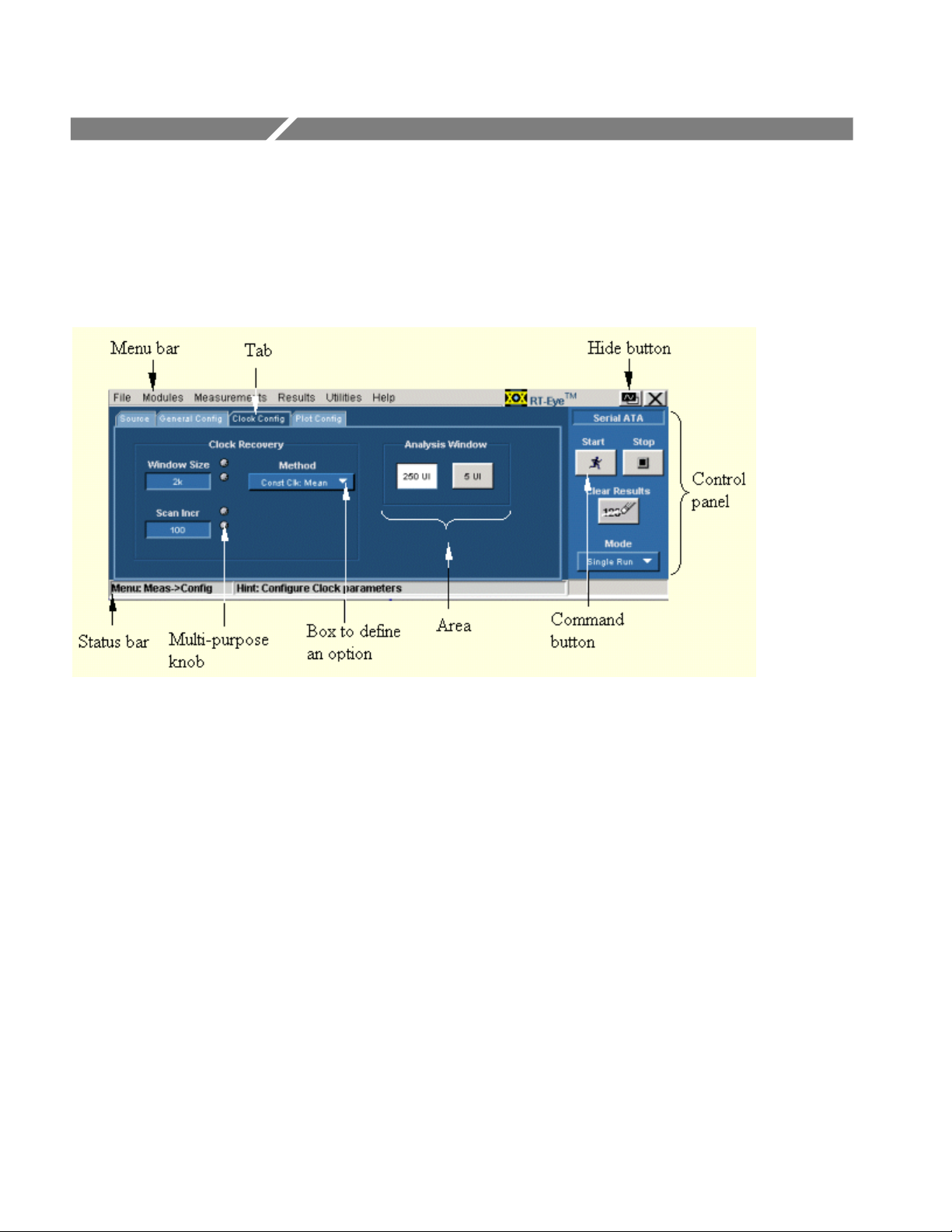
Opt. SST Application View
Figure 1: Application view
Option SST Serial ATA and Serial Attached SCSI Analysis Module
14

Application User Interface Items
Table 3: Application user interface and their description
Item Description
Area Visual frame that encloses a set of related options
Box Use to define an option; enter a value with the keypad or
multipurpose knob
Browse Displays a window where you can look through a list of dir ectori es
and files
Button Use to define an options; not a command button
Check box Use to select or clear an option
Command button Initiates an immediate action, such as the Star t command button in
the Control panel
Control panel Locat ed to the right of the applic ation; contains command butt ons t hat
you use often
List box Use to define from a list
Menu All options in the application window (except the Control panel) that
display when you select a menu bar item
Menu bar Located at the top of the application display and c ontains the
application menus
Option Any named button (other than the command button) or any named
box that defines a contr ol or task
Status bar Line located at the bottom of the application displ ay that shows the
name of the current menu (location) and the next step that y ou mi ght
take (action)
Scroll bar Vertical or horizontal bar at the side or bottom of a display area that
you use to move around in that area
Tab Short cut to a menu in the menu bar or a category of menu options;
most tabs are short cuts
Virtual keyboard On-screen keyboard t hat you can use to enter values (numeri c
keyboard) or al phanumer ic strings (text) for descriptions and fil e
names
Operating Basics
Option SST Serial ATA and Serial Attached SCSI Analysis Module
15

Operating Basics
Serial ATA and SAS Measurements
The following tables list the Serial ATA and SAS measurements that the modules
support.
Table 4: Default directory names and their use
Measurement Description
Eye Measures, analyzes, and c har ac terizes the differ ential
output voltage, jitter, rise and fall time for transition and
non-transition bits
Bit Rate Measures the inverse of the average bit time for the
clock recovery window
Differential Skew Measures the time difference between the single-ended
mid-point of the TX+/ RX+ si gnal ri si ng/falling edge and
the single-ended mid-point of the TX−/RX− signal
falling/rising edge
Rise and Fall Time Measure s the rise and fall times of the waveform. The
rise and fall times are defined over a 20%-80% output
level change from the High and Low reference levels
Unit Interval Measures the tim e requi red to transmit one bit
Differential Voltage Measures the minimum and maximum differential
voltage amplitude for a given data pattern
AC Common Mode Voltage Measures the maxim um sinusoi dal amplitude
16
Option SST Serial ATA and Serial Attached SCSI Analysis Module

Out Of Band Tests
Table 5: Default directory names and their use
Out of Band Tests Description
COMINIT Is used by the device t o request a reset from the host in
accordance with a par ticular sequence of bur sts
COMRESET Is indicated by transmitting bursts of data separated by
an idle bus condit ion. The OOB COMRESET signal
consists of no less than six data bursts with i nter- burst
temporal spaci ng
COM WAKE The OOB COMWAKE signaling consists of no less than
six data bursts inc luding inter-burst spacing
Menus
Operating Basics
Menus
The Option SST application consists of two software plug-in modules that run on
the RT-Eye Serial Data Compliance and Analysis application − Serial ATA
(SATA) and SAS. Each module has a menu that allows you to save and recall
files, select measurements and configure them, view results, and generate reports.
Option SST Serial ATA and Serial Attached SCSI Analysis Module
17

Operating Basics
Figure 2: Default directory names and their use
File Menu
You can use the File menus to save and recall different application setups and
recently accessed files.
Note: The File> Save function saves application settings in an .ini file and the
settings of the oscilloscope application in a .set file with a matching name.
If an oscilloscope .set file with a matching name is found when you recall an
application setup file, then the oscilloscope settings are also recalled. If the .set
file is missing or cannot be opened by the oscilloscope, then the application
recalls the application settings and displays a message that the Recall of the .set
file failed.
Do not edit a setup file or recall a file not generated by the application.
Click File from the application menu bar.
18
Option SST Serial ATA and Serial Attached SCSI Analysis Module
 Loading...