

Page 1

Instructions
Option FHD
Front Hard Drive
071-1223-00
Warning
The servicing instructions are for use by qualified
personnel only. To avoid personal injury, do not
perform any servicing unless you are qualified to
do so. Refer to all safety summaries prior to
performing service.
www.tektronix.com
*P071122300*
071122300
Page 2

Copyright © Tektronix, Inc. All rights reserved.
Tektronix products are covered by U.S. and foreign patents, issued and pending. Information in this publication supercedes
that in all previously published material. Specifications and price change privileges reserved.
Tektronix, Inc., P.O. Box 500, Beaverton, OR 97077
TEKTRONIX and TEK are registered tradem arks of Tektronix, Inc.
Page 3

General Safety Summary
Review the following safety precautions to avoid injury and prevent damage to
this product or any products connected to it. To avoid potential hazards, use this
product only as specified.
Only qualified personnel should perform service procedures.
ToAvoidFireor
Personal Injury
Use Proper Power Cord. Use only the power cord specified for this product and
certified for the country of use.
Connect and Disconnect Properly. Do not connect or disconnect probes or test
leads while they are connected to a voltage source.
Ground the Product. This product is grounded through the grounding conductor
of the power cord. To avoid electric shock, the grounding conductor must be
connected to earth ground. Before making connections to the input or output
terminals of the product, ensure that the product is properly grounded.
Observe All Terminal Ratings. To avoid fire or shock hazard, observe all ratings
and markings on the product. Consult the product manual for further ratings
information before making connections to the product.
Do Not Operate Without Covers. Do not operate this product with covers or panels
removed.
Use Proper Fuse. Use only the fuse type and rating specified for this product.
Avoid Exposed Circuitry. Do not touch exposed connections and components
when power is present.
Wear Eye Protection. Wear eye protection if exposure to high-intensity rays or
laser radiation exists.
Option FHD
Do Not Operate With Suspected Failures. If you suspect there is damage to this
product, have it inspected by qualified service personnel.
Do Not Operate in Wet/Damp Conditions.
Do Not Operate in an Explosive Atmosphere.
Keep Product Surfaces Clean and Dry.
Provide Proper Ventilation. Refer to the instrument’s installation instructions for
details on installing the product so it has proper ventilation.
i
Page 4
General Safety Summary
Symbols and Terms
Terms in this Manual. These terms may appear in this manual:
WARNING. Warning statements identify conditions or practices that could result
in injury or loss of life.
CAUTION. Caution statements identify conditions or practices that could result in
damage to this product or other property.
Terms on the Product. These terms may appear on the product:
DANGER indicates an injury hazard immediately accessible as you read the
marking.
WARNING indicates an injury hazard not immediately accessible as you read the
marking.
CAUTION indicates a hazard to property including the product.
Symbols on the Product. The following symbols may appear on the product:
CAUTION
Refer to Manual
Mains Disconnected
OFF (Power)
WARNING
High Voltage
Mains Connected
ON (Power)
Protective Ground
(Earth) Terminal
Standby
ii
Option FHD
Page 5

Service Safety Summary
Only qualified personnel should perform service procedures. Read this Service
Safety Summary and the General Safety Summary before performing any service
procedures.
Do Not Service Alone. Do not perform internal service or adjustments of this
product unless another person capable of rendering first aid and resuscitation is
present.
Disconnect Power. To avoid electric shock, switch off the instrument power, then
disconnect the power cord from the mains power.
Use Care When Servicing With Power On. Dangerous voltages or currents may
exist in this product. Disconnect power, remove battery (if applicable), and
disconnect test leads before removing protective panels, soldering, or replacing
components.
To avoid electric shock, do not touch exposed connections.
Option FHD
iii
Page 6

Service Safety Summary
iv
Option FHD
Page 7
Description and Operation
Option FHD is a removable hard-disk drive at the front of the instrument. With
this option the hard drive at the rear of the instrument and the floppy drive at the
front of the instrument are not available.
All instrument functions that require the floppy drive are unavailable. All
instrument functions that require a hard disk use the removable hard drive
located in the front panel. All other instrument functions remain the same as the
standard instrument.
CAUTION. Do not lift or support the instrument by the hard-drive handle.
Moving the Disk
If you move the hard disk to another instrument, you must perform a signal path
compensation.
1. To compensate the signal path, select Utilities and then Instrument Calibra-
tion.
Disk Removal
2. Read the Calibration Instructions.
3. Press the Calibrate button.
4. After the calibration successfully completes, the Status is Pass.
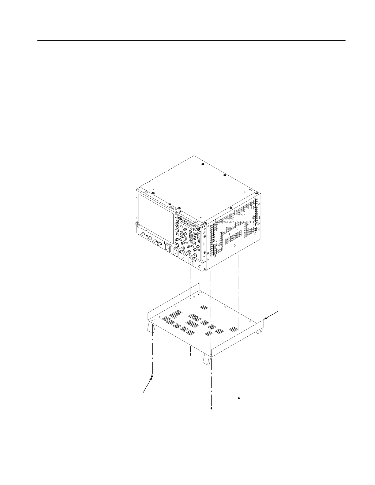
To remove the disk drive from the instrument, do the following procedure:
1. Set the oscilloscope so that its bottom is down on the work surface and its
front panel is facing you. See Figure 1--1 on page 1--2.
CAUTION. Do not remove the replaceable hard disk drive when the instrument is
powered on. The replaceable hard disk drive may be permanently damaged if it
is removed while the instrument is powered on.
a. Verify that the oscilloscope is powered off.
Option FHD
1- 1
Page 8

Description and Operation
b. To unlock the hard drive assembly, rotate both thumb screws counter-
clockwise.
c. Grasp the hard disk drive assembly by its handle, and pull the assembly
out of the instrument.
2. Reinstallation: Do in reverse step 1 to reinstall the hard disk drive assembly.
Handle
Thumb
screw (2)
1- 2
Figure 1- 1: Hard disk drive removal
Option FHD
Page 9

WARNING
The following servicing instructions are for use only by qualified personnel. To
avoid injury, do not perform any servicing other than that stated in the operating
instructions unless you are qualified to do so. Refer to all safety summaries before
performing any service.
Page 10

Page 11

Removal and Installation Procedures
This subsection contains procedures for removal and installation of all mechanical and electrical modules.
WARNING. Before doing this or any other procedure in this manual, read the
Safety Summaries found at the beginning of this manual.
This subsection contains the following items:
H List of tools required to remove and disassemble all modules.
H Procedures for removal and reinstallation of the electrical and mechanical
modules.
WARNING. Before doing any procedure in this subsection, disconnect the power
cord from the line voltage source. Failure to do so could cause serious injury or
death.
Equipment Required. Most modules can be removed with a screwdriver handle
mounted with a size T-15, Torx screwdriver tip. Use this tool whenever a
procedure step instructs you to remove or install a screw unless a different size
screwdriver is specified in that step.
Table 2- 1: Tools required for module rem oval
Item
no.
1 Screwdriver handle Accepts Torx-driver bits 620-440
2 T-10 Torx tip Used for removing the electrical or
3 T-15 Torx tip Used for removing most instrument
4
5 #0 Phillips screwdriver Screwdriver for removing small
6 MA-800G Soldering Aid Used to remove the front-panel trim Standard tool
Name Description
optical module chassis. Torx-driver
bit for T-10 size screw heads
screws. Torx-driver bit for T-15 size
screw heads
1
/8inch flat-bladed screw-
driver
Screwdriver for unlocking cable
connectors
Phillips screws
General tool
number
640-235
640-247
Standard tool
Standard tool
Option FHD
2- 1
Page 12

Removal and Installation Procedures
Procedures for External Modules
The following procedures are found here and are listed in order presented.
H Hard disk drive
H Trim (all)
H Bottom cover
H Left and Right covers
H Line Fuse and Line Cord
Disk Drive
To remove the hard disk drive from the cartridge, do the following procedure:
1. Remove the hard disk from the instrument. See Disk Removal on page 1--1.
2. Remove the hard disk drive from the cartridge: SeeFigure2--1on
page 2--2.
a. Remove the four #0 Phillips screws that fasten the hard disk drive to the
cartridge.
b. Carefully remove the hard disk drive from the cartridge, and remove the
cable assembly from the connector on the hard disk drive.
Remove 4 screws
Trim and Carrying Handle
2- 2
Figure 2- 1: Removing the hard disk drive from the cartridge
1. Locate module to be removed: Locate the Trim in the locator diagram. See
Figure 2--2 on page 2--4.
2. Remove the front-panel trim: Use Figure 2--2 on page 2--4 as a guide.
a. To prevent the power button from falling out of the front-panel trim,
place a piece of tape over the button.
Option FHD
Page 13

Removal and Installation Procedures
b. Grasp the trim ring by its top edge and pull toward you to detach the
three plastic snaps. (Alternatively, you can use a flat-bladed screwdriver
or other small prying tool to help you detach the snaps.)
c. Swing the bottom of the ring upward and off the front panel.
3. Remove the acquisition trim: Use Figure 2--2 on page 2--4 as a guide.
a. Remove the three T-15 Torx screws that secure the acquisition trim to
the instrument.
b. Remove the acquisition trim from the instrument.
4. Remove the top cover trim: Use Figure 2--2 on page 2--4 as a guide.
a. Remove the accessory pouch; it snaps off.
b. Remove the four T-15 Torx screws that secure the top cover trim to the
instrument. The T-15 Torx screws also secure the snap studs to the top
cover.
c. Remove the top cover trim from the instrument.
5. Remove the carrying handle and the right/left side trim panels: Use
Figure 2--2 on page 2--4 as a guide.
a. Remove the T-15 Torx screws that secure the handle to the instrument.
Remove the handle from the instrument.
b. Slide the side trim panels towards the rear of the instrument allowing the
tabs to clear the cover openings, and then pull out to remove the panels
from the instrument.
6. Reinstallation: Do in reverse steps 2 through 5 to reinstall the appropriate
trim.
Option FHD
2- 3
Page 14

Removal and Installation Procedures
Front-panel trim
Left side trim
T-15 Torx screw
(4)
Snap stud (4)
Top cover trim
Right side trim
Front-panel cover
Figure 2- 2: Trim removal
Acquisition trim
Carrying handle
T-15 Torx
screw (3)
Soldering aid
To remove the trim ring, slide the flat
end of a soldering aid into the side
slot on the trim ring. Press in, lift up
to hook it underneath, and then pry
up.
T-15 Torx screw
(2)
2- 4
Option FHD
Page 15
Removal and Installation Procedures
Bottom Cover
1. Remove the bottom cover: SeeFigure2--3onpage2--5.
2. Orient the instrument: Set the instrument so that its top is down on the work
surface and its bottom is facing you.
a. Remove the four T-15 Torx screws that secure the bottom cover to the
instrument.
b. Remove the bottom cover from the instrument.
3. Reinstallation: Do in reverse steps a and b to reinstall the bottom cover.
Option FHD
Bottom cover
T-15 Torx
screw (4)
Figure 2- 3: Bottom cover removal
2- 5
Page 16
Removal and Installation Procedures
Covers
1. Remove the left and right covers: See Figures 2--4 and 2--5 on pages 2--7
and 2--8.
H Trim (all)
H Bottom cover
2. Orient the instrument: Set the instrument so that its rear is on the work
surface and the front of the instrument is facing you.
NOTE. All mounting screw holes are indicated by a star etched around the
mounting hole.
a. Remove the eleven T-15 Torx screws that secure the covers to the top
and both sides of the chassis.
b. Remove the seven T-15 Torx screws that secure the covers to the bottom
of the chassis.
c. Pull the bottom-right cover down, and slide to the right to remove from
the instrument. Pull the top-left cover upward and slide to the left to
remove from the instrument.
CAUTION. Take care not to bind or snag the covers on the internal cabling of the
instrument as you remove or install.
3. Reinstallation: Do in reverse steps a through c to reinstall the cabinet covers.
2- 6
Option FHD
Page 17
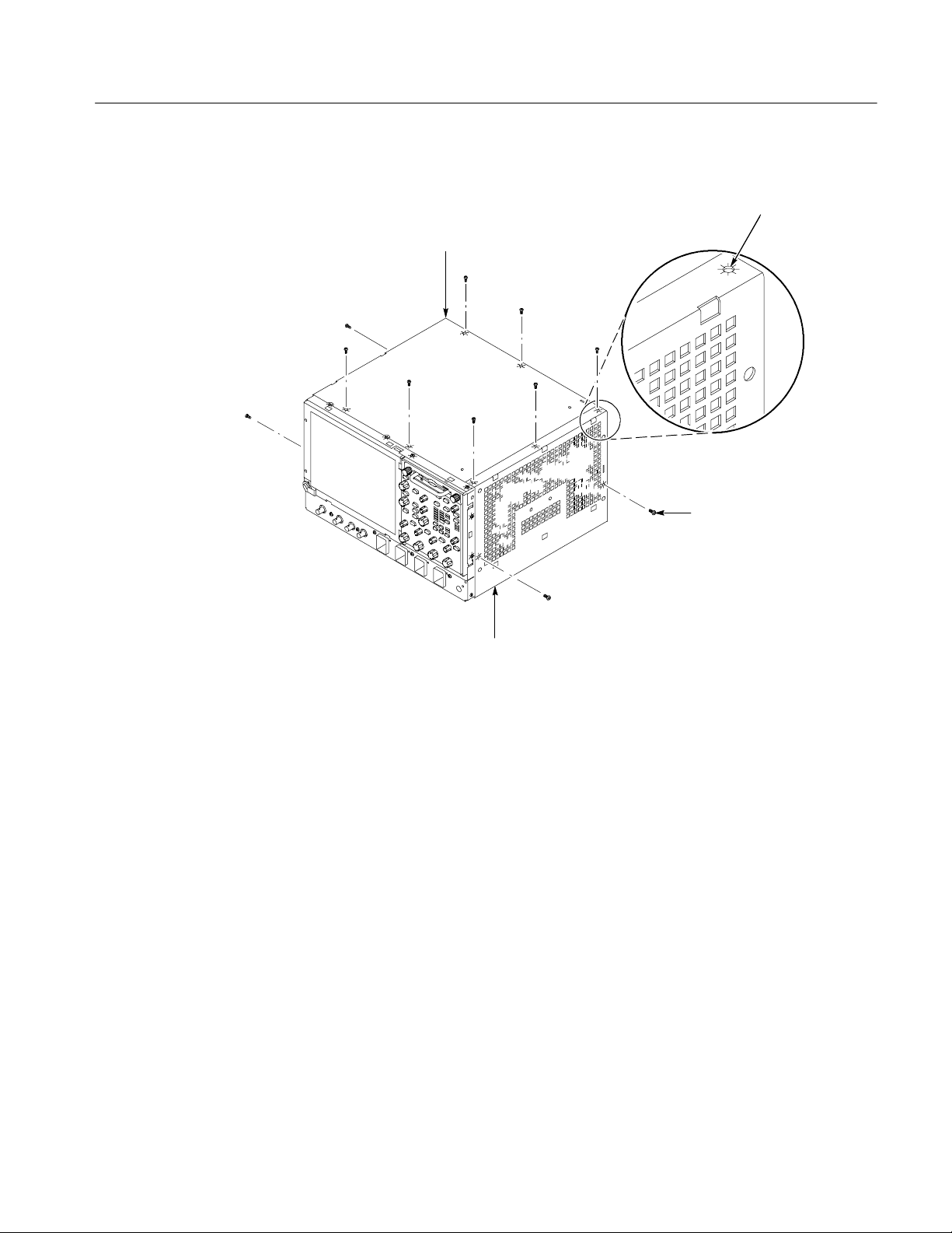
Left side cover
Removal and Installation Procedures
All left and right cover
mounting holes are
indicated as shown.
T-15 Torx
screw (11)
Right side cover
Figure 2- 4: Cover removal
Option FHD
2- 7
Page 18
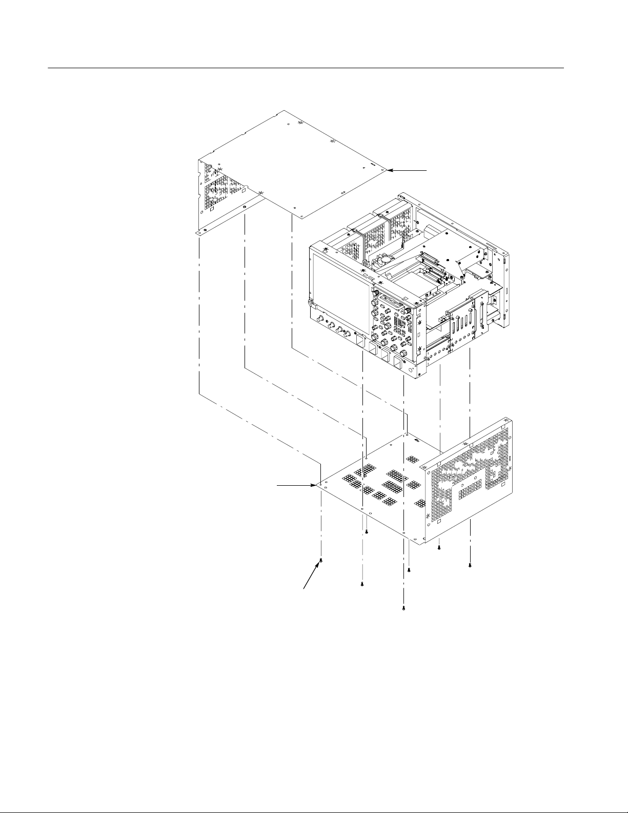
Removal and Installation Procedures
Left side cover
2- 8
Right side cover
T-15 Torx screw (7)
Figure 2- 5: Cover removal
Option FHD
Page 19

Procedures for Modules
Removal and Installation Procedures
You should have completed the Procedures for External Modules before doing
many of the procedures in this collection. The procedures found here are listed in
disassembly order:
H Front Panel assembly
H Hard Disk Drive
H NLX Board
H Acquisition Board
Front Panel Assembly
1. Locate module to be removed: Locate the Front-Panel assembly in
Figure 2--6 on page 2--10. Additional modules to be Removed:
H Trim (Front panel)
2. Remove the Front-Panel assembly: SeeFigure2--6onpage2--10.
3. Orient the instrument: Set the instrument so that its bottom is down on the
work surface and its front panel is facing you.
a. Remove the six T-15 Torxdrive screws that secure the front-panel
assembly to the front chassis.
b. Grasp the top of front-panel assembly and pull forward to allow access
to the ribbon-cable connector on the front-panel board.
1
c. Use the
connector lock up to disconnect the J1 flex cable from the display
module assembly. See Figure 2--7 on page 2--11. Note the connector
pin 1 index mark and the black stripe on the cable for later reassembly.
d. Pull the Front-Panel assembly forward and remove from the instrument.
4. Reinstallation: Do in reverse steps a through d to reinstall the front-panel
assembly.
@8inch flat-bladed screwdriver to carefully lift the J1 cable
Option FHD
2- 9
Page 20
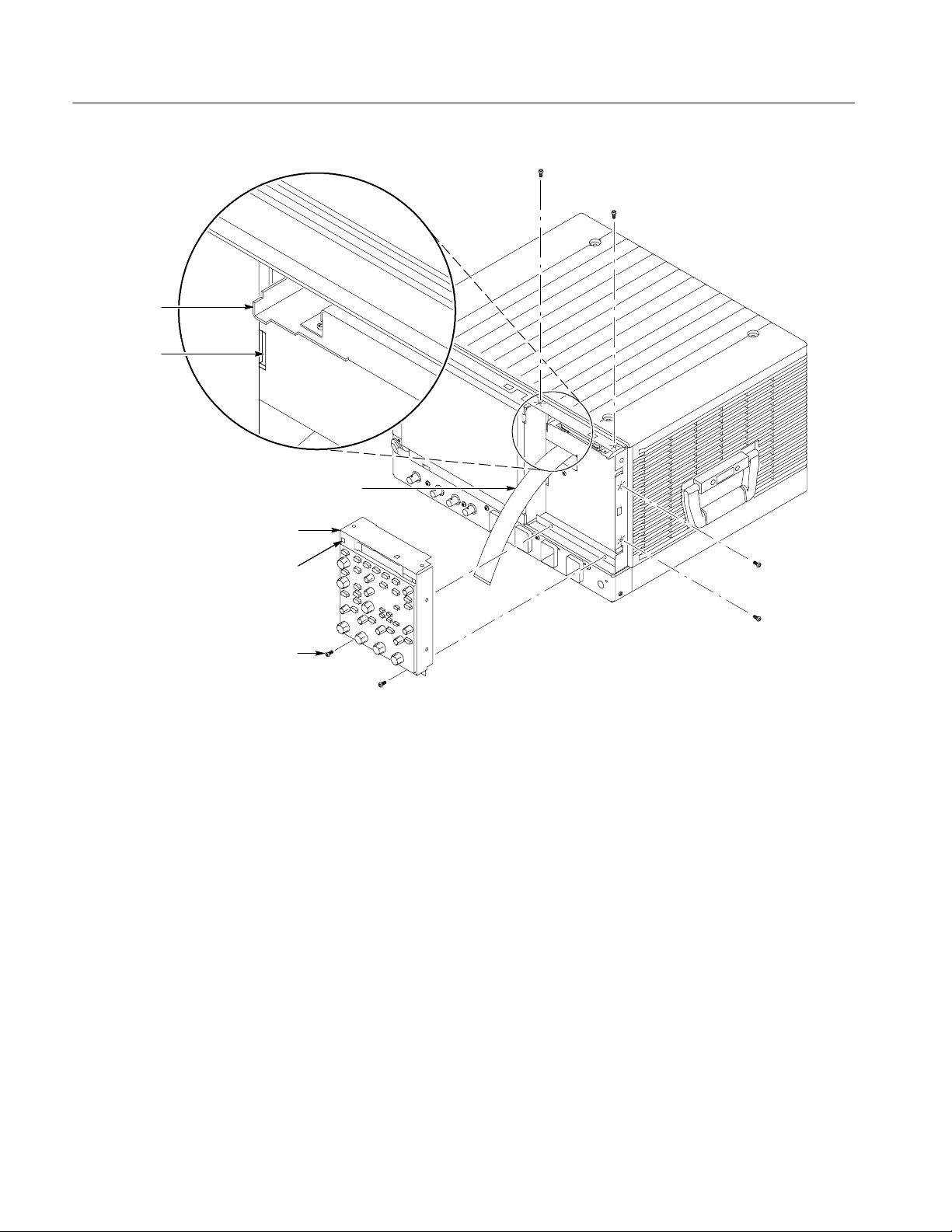
Removal and Installation Procedures
Hard disk
support tab (2)
Chassis
slot (2)
J1 ribbon cable
Front-panel
assembly
Front-panel square
opening (2)
T--15 Torxdrive
screw (6)
Figure 2- 6: Front-panel assembly removal
2- 10
Option FHD
Page 21
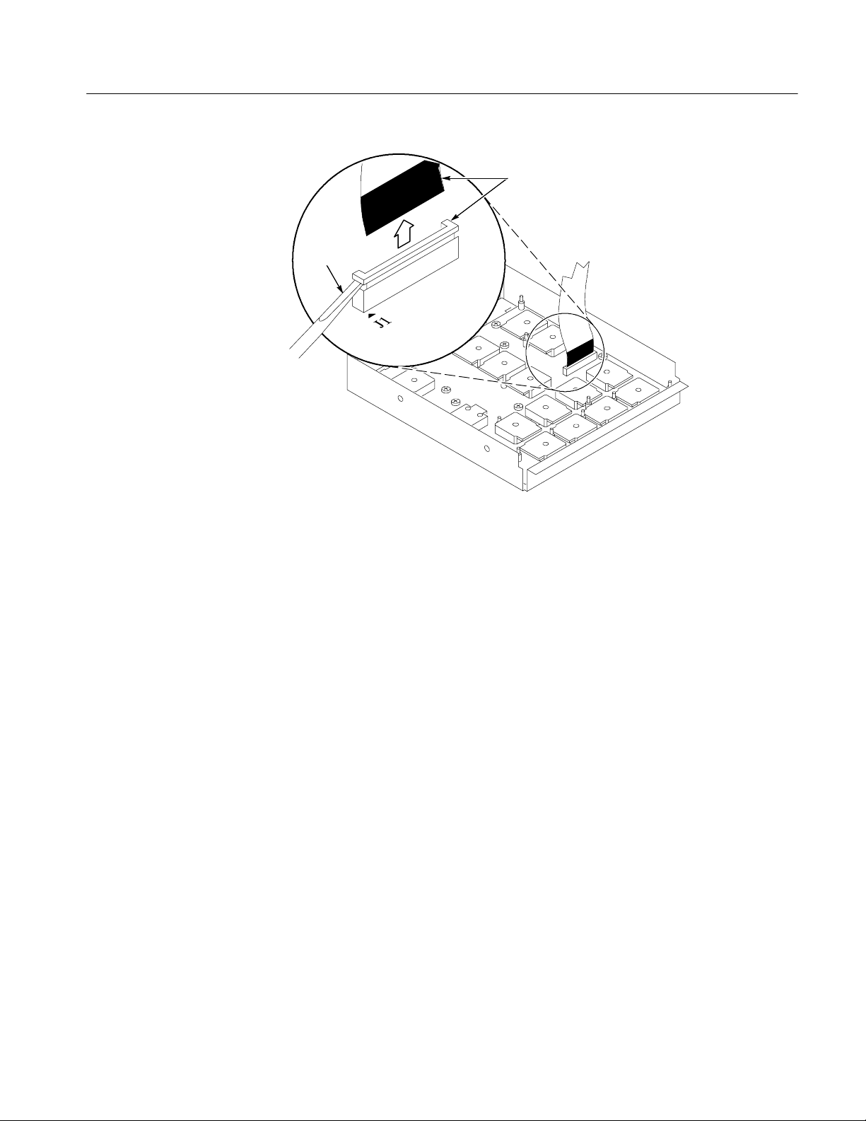
Screwdriver
Removal and Installation Procedures
Black stripe
toward connector
Figure 2- 7: J1 flex cable connector removal
Option FHD
2- 11
Page 22

Removal and Installation Procedures
Hard Disk Drive Bracket
1. Locate modules to be removed: Locate the Hard Disk Drive in the locator
diagram Internal Modules, Figure 2--8 on page 2--13. Additional modules to
be Removed:
H Trim (front panel and top)
H Front Panel assembly
2. Remove the Hard disk drive assembly: Use Figure 2--9 on page 2--15 as a
guide.
3. Orient the instrument: Set the instrument so that its bottom is down on the
work surface and its front panel is facing you.
a. Remove the two T-15 Torx screws that secure the Hard disk drive
assembly to the bracket.
b. Remove the T-15 Torx screw that secures the hard disk drive assembly to
the CD drive bracket.
c. Slide the hard drive assembly out toward the front of the instrument far
enough to allow you to disconnect the ribbon cable connector.
d. Remove the hard drive bracket from the instrument.
4. Reinstallation: Do in reverse steps a through c to reinstall the hard disk drive
assembly.
2- 12
Option FHD
Page 23

Fan assembly
Display adapter board
Hard drive
Removal and Installation Procedures
CD drive
CD drive Interface
board
Microprocessor,
fan and heat sink
NLX board
Riser board
THan
Power PC (PPC)
board
Low-voltage power
supply assembly
Power flex circuit
Display module assembly
Figure 2- 8: Internal modules
Front panel
assembly
Front panel
board
Front panel
keypad
Front
distribution
board
Acquisition board
PA bus
board
Rear
distribution
board
Option FHD
2- 13
Page 24

Removal and Installation Procedures
NLX Board
1. Locate module to be removed: Locate the NLX Board in the locator diagram
Internal Modules, Figure 2--8, on page 2--13. Additional modules to be
removed:
H Trim (all)
H Bottom cover
H Left and Right covers
H Front Panel
H Hard Drive assembly
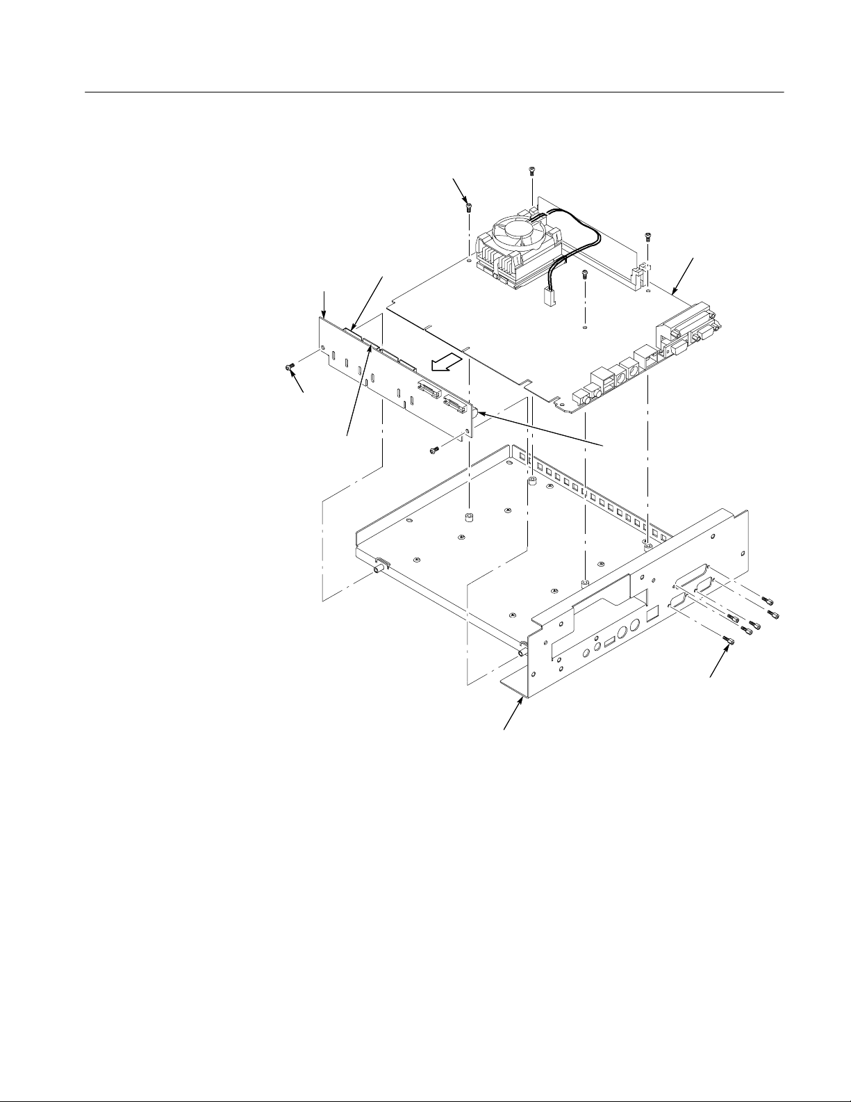
2. Remove the NLX Board assembly: See Figure 2--9 on page 2--15.
3. Orient the instrument: Set the instrument so that its bottom is down on the
work surface and its top is facing you.
a. Remove the five T-15 Torxdrive screws that secure NLX board assembly
to the chassis.
b. Remove the five T-15 Torxdrive screws that secure NLX board assembly
and the rear cover plate to the rear chassis. Remove the cover plate from
the instrument.
c. Grasp the front edge of the NLX board assembly and pull up on the
assembly to disconnect the Riser Adapter from the Processor board edge
connector.
d. Remove the NLX board assembly from the instrument.
2- 14
Option FHD
Page 25

T--15 Torx
NLX board
assembly
Riser adapter
board
T--15 Torx
screw (1)
T--15 Torx
screw (2)
Removal and Installation Procedures
Hard/CD drive
bracket
screw (5)
Option FHD
Remove hard
drive bracket
from front
chassis
Processor board
edge connector
Remove hard drive cable
T--15 Torx
screw (3)
T--15 Torx
screw( 2)
Figure 2- 9: NLX assembly and hard disk drive removal
4. Remove the Riser Adapter and NLX Boards: See Figure 2--10 on page 2--17.
a. Remove the two T-15 Torxdrive screws that secure Riser Adapter board
to the NLX support bracket.
b. Disconnect the ribbon cable connectors from the hard drive and CD
drive.
2- 15
Page 26

Removal and Installation Procedures
5. Reinstallation: Do in reverse steps 3 and 4 to reinstall the NLX board.
c. Grasp the Riser board and pull it straight out to disconnect J510 edge
card connector from the NLX board. Remove the Riser Adapter board
from the NLX board assembly.
d. Remove the four T-15 Torxdrive screws that secure NLX board to the
NLX support bracket.
e. Remove the six 3/16 nut posts that secure the three connectors to the rear
of the support bracket. Then remove the NLX board from the support
bracket.
f. Remove the NLX board from the support bracket.
2- 16
Option FHD
Page 27
T--15 Torx
screw (4)
Removal and Installation Procedures
Riser
adapter
board
T--15 Torx
screw (2)
CD drive cable
connector
Hard drive
cable
connector
NLX board
J510
Option FHD
Nut post (6)
NLX support
bracket
Figure 2- 10: Riser adapter and NLX board removal
2- 17
Page 28

Removal and Installation Procedures
2- 18
Option FHD
Page 29

Mechanical Parts List
This section contains a list of the replaceable modules for Option FHD. Use this
list to identify and order replacement parts. See your instrument service manual
for all other replacement parts
Mfr. Code to Manufacturer
Cross Index
The following table cross indexes codes, names, and addresses of manufacturers
or vendors of components listed in the parts list.
Manufacturers cross index
Mfr.
code
060D9 TENSOLITE COMPANY PRECISION HARNESS AND ASSEMBLY
0KB01 STAUFFER SUPPLY CO 810 SE SHERMAN PORTLAND, OR 97214--4657
22670 GM NAMEPLATE INCORPORATED 2040 15TH AVE WEST SEATTLE, WA 98119--2783
57924 BOURNS INC INTEGRATED TECHNOLOGY DIV.
7X318 KASO PLASTICS INC 5720--C NE 121ST AVE, STE 110 VANCOUVER, WA 98682
80009 TEKTRONIX INC 14150 SW KARL BRAUN DR
9F560 IBM CORPORATION 420 E SOUTH TEMPLE ST SALT LAKE CITY, UT 84145
TK1943 NEILSEN MANUFACTURING INC 3501 PORTLAND RD NE SALEM, OR 97303
Manufacturer Address City, state, zip code
VANCOUVER, WA 98661
3000 COLUMBIA HOUSE BLVD
#120
LOGAN, UT 84321
1400 NORTH 1000 WEST
BEAVERTON, OR 97077--0001
PO BOX 500
Replaceable Parts List
Fig. &
index
number
1--1 200--4794--00 1 COVER,FRONT:PROTECTIVE,FR110,TEK
--2 101--0161--01 1 TRIM,FRONT:PCABS,17.200W X 8.450H,SILVER GRAY 7X318 2TEK1648
Tektronix part
number
Serial no.
effective
Serial no.
discont’d
Qty Name & description
BLUE,TDS7404,TDS7154
Mfr.
code
7X318 200--4794--00
Mfr. part number
Option FHD
3- 1
Page 30

Mechanical Parts List
1
Figure 3- 1: External parts
2
3- 2
Option FHD
Page 31

Replaceable Parts List
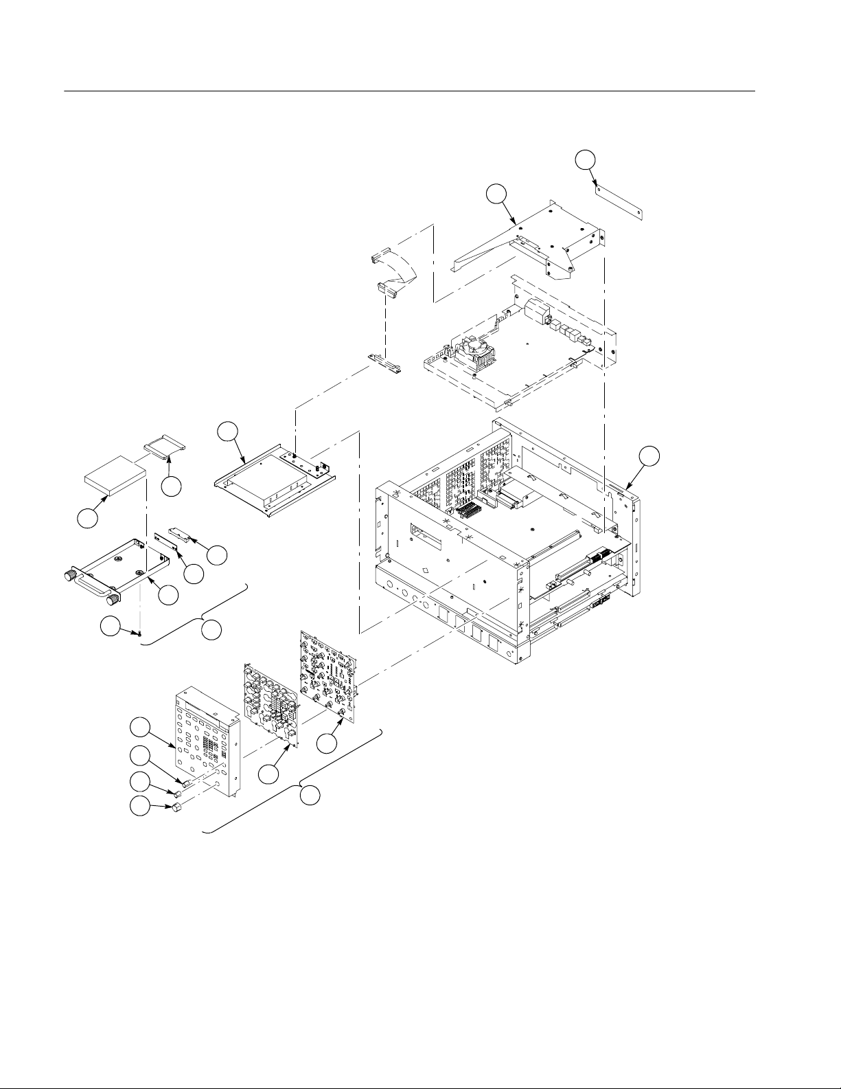
Mechanical Parts List
Fig. &
index
number
2--1 441--2183--02 1 CHASSIS ASSY:REAR DRIVE BAY,HD & CD,0.050 AL TK1943 441-- 2183-- 02
--2 200--4782--00 1 COVER, REAR HD PLATE 7X318 200--4782--00
--3 441--2302--00 1 CHASSIS ASSY:SHEET METAL,TDS7404, TDS7154 TK1943 441-- 2302-- 00
--4 614--2762--00 1 PANEL ASSEMBLY:FRONT (ITEMS 5 THROUGH 10) 80009 614--2762--00
--5 679--5366--00 1 CKT BD SUBASSY:FRONT PANEL 57924 3777S--TEK--030
--6 260--2762--00 1 SWI TCH,KEYPAD:ELASTOMERIC,FRONT PANEL 22670 260--2762--00
--7 366--0821--00 7 KNOB,CAP:0.650 D,PC/ABS,SILVER GRAY 22670 366--0821--00
--8 366--0820--00 7 KNOB,CAP:0.425 DIA,PC/ABS,SILVER GRAY 22670 366--0820--00
--9 366--0819--00 1 KNOB,EPS:PUSH BUTTON,PC/ABS,SILVER GRAY 22670 366--0819--00
--10 333--4439--00
--11 650--4498--00 1 RHDD ASSEMBLY:W/O SW (ITEMS 12 THROUGH 17) 80009 650--4498--00
--12 674--4378--00 1 CKT BD SUBASSY:HARD DISK DRIVE INTERFACE 80009 679--4378--00
--13 679--4378--00 1 CKT BD SUBASSY:HARD DISK DRIVE INTERFACE 80009 679--4378--00
--14 437--0506--00 1 CABINET ASSY:REMOVEABLE HARD DISK DRIVE HOLDER 7X318 437-- 0506-- 00
--15 211--1081--00 4 SCREW,MACHINE:M3 X 0.5 X 3.5MM,FLAT WAFER
--16 119--6733--00 1 DISK DRIVE:WINCHESTER,2.5 IN,20GB,SINGLE PLATTER 9F560 07N8325
--17 174--4747--00 1 CA ASSY,SP:RIBBON,44,28 AWG,1MM,1.0 L,2 X 22 060D9 174--4747--00
--18 407--4917--00 1 BRACKET:FLOPPY DRIVE,6.064 X 5.075,AL TK1943 407-- 4917-- 00
Tektronix part
number
333--4444--00
Serial no.
effective
Serial no.
discont’d
Qty Name & description
11SUBPANEL ASSY:OFF SET,W/BEZEL,TDS7404
SUBPANEL ASSY:OFF SET,W/BEZEL, TDS7154
HD,PHL,0.0002 STL ZI PL
Mfr.
code
7X318
7X318
0KB01 211--1081--00
Mfr. part number
333--4439--00
333--4444--00
Option FHD
3- 3
Page 32
Mechanical Parts List
2
1
18
3
17
16
12
13
14
15
10
9
8
7
11
Figure 3- 2: Front panel and drives
5
6
4
3- 4
Option FHD
 Loading...