


xx
Optical Signal
ZZZ
Plug-in Application
Printable Help Document
*P077124900*
077-1249-00


Optical Signal
Plug-in Application
ZZZ
Printable Help Document
w.tek.com
ww
077-1249-00

Copyright © Tektronix. All rights reserved. Licensed software products are owned by Tektronix or its
subsidiaries or suppliers, and are protected by national copyright laws and international treaty provisions.
Tektronix products are covered by U.S. and foreign patents, issued and pending. Information in this
publication supersedes that in all previously published material. Specifications and price change privileges
reserved.
TEKTRONIX and TEK are registered trademarks o f Tektronix, Inc.
®
SourceXpress
is a registered trademark of Tektronix, Inc.
Microsoft, Windows, Windows XP Professional, and Windows 7 are registered trademarks of Microsoft
Corporation.
Supports High Speed Serial Plug-in application Version 1.0 and above.
Help part number: 076–0397–00
PDF of Help system part number: 077–1249–00
Contacting Tektronix
Tektronix, Inc.
14150 SW Karl Braun Drive
ox 500
P. O . B
Beaverton, OR 97077
USA
For product information, sales , service, and technical support:
In North America, call 1-800-833-9200.
ldwide, v isit www.tek.com
Wor
to find contacts in your area.

Table of Contents
Introduction
Welcome............................................................................................................. 1
Key features ......................................................................................................... 2
Documentation......................................... ................................ ............................. 2
Support information....... .................................. ................................ ....................... 3
Orientation
Elements of the display ............................................................................................ 5
Plug-in selection ......................................... .................................. ......................... 5
Compile button..................... ................................ ................................ ................. 6
Compile settings .................................................................................................... 7
Reset Plug-in button......... ................................ .................................. .................... 10
Help button ................. ................................ ................................ ........................ 10
Table of Contents
Setup tab
Setup tab .............................. ................................ ................................ .............. 11
Basic Setup parameters ........................................................................................... 11
Modulation parameters............................................................................................ 12
Filter parameters .. . . . . . . . . . . . . . . . . . . . . . . . . . . . . . . . . . . . . . . . . . . . . . . . . . . . . . . . . . . . . . . . . . . . . . . . . . . . . . . . . . . . .............. 17
X Data Source parameters ........................................................................................ 18
Y Data Source parameters ........................................................................................ 18
PRBS Editor........................................................................................................ 19
IQ Impairments
IQ Impairments .................................................................................................... 21
S-Parameter
S-Parameter license ............................................................................................... 23
S-Parameter ........................................................................................................ 23
S-Parameter file descriptions .......................... ................................ ...................... 26
Aggressor signals ............................................................................................. 28
Symbol mapping
Symbol mapping......................................... .................................. ........................ 29
Licensing
Licensing ..... ................................ ................................ .................................. .... 31
Optical Signal Printable Help Document i

Table of Contents
Index
ii Optical Signal Printable Help Document

Introduction Welcom e
Welcome
The Optical Signal plug-in is a waveform creation application that is used to create various kinds of
waveforms and modulation schemes to test the communication paths between optical components.
The Optical Signals are typically output via an AWG connected to an optical module, converting the
electrical signal to an optical signal. The optical signal is then transmitted to a Devise Under Test (DUT).
The Optical Signal plug-in is designed to integrate and operate seamlessly as an enhancement to the
SourceXpress waveform creation software application or to an AWG70000A series arbitrary waveform
generator
Once installed, the plug-in becomes available as another waveform plug-in application.
This illustration shows the Optical Signal plug-in v iewed from the SourceXpress application. The plug-in
is identical whether it is used from SourceXpress or from an AWG70000A series instrument.
.
Optical Signal Printable Help Document 1

Introduction Key features
Key features
Allows users to create waveforms for either single or dual polarization.
Along with commonly used modulations like QAM and PAM, users can also define their own
modulation scheme.
Users have the option to use a single data source for the carrier or use multiple data sources.
Documentation
In addition to this application Help system, the following documentation is available for the software.
All documentation is available on the Tektronix Web site (www.tek.com/manual/downloads
To read about Use these documents
Optical plug-in operation and user interface help Access the plug-in application help from the plug-in Help menu for
information on all controls and elements on screen.
The Optical plug-in help system is also available in PDF format located in
the program’s installation folder and also available on the Tektronix web
site.
Optical plug-in programmer commands Access the plug-in programmer manual for the syntax of remote commands
specific to the plug-in.
This is available on the Tektronix web site.
SourceXpress operation and user interface help Access the SourceXpress application help from the Help menu for
information on all controls and elements on screen.
The SourceXpress help system is also available in PDF format, available
on the Tektronix web site.
SourceXpress programmer commands Access the SourceXpress programmer manual for the syntax of remote
commands.
This document is available in PDF format located in the program’s
installation folder and also available on the Tektronix web site.
Connected instrument operation and user
interface help (such as an AWG70002A)
For operation and interface help of a connected instrument, refer to the
instrument’s documentation.
This is available with the instrument or on the Tektronix web site.
).
Connected instrument programmer commands
(such as an AWG70002A)
xxx
For programming information of a connected instrument, refer to the
instrument’s documentation. This is available with the instrument or on
the Tektronix web site.
2 Optical Signal Printable Help Document

Introduction Support information
Support information
Tektronix offers the following services in support of their products:
Technical Support. For application-related questions about a Tektronix product, contact us by
telephone or email ).
Service Support. For service-related questions about a Tektronix product, contact us by telephone
or email ).
Tektronix also offers extended warranty and calibration programs as options on many products. Contact
your local Tektronix distributor or sales office.
Optical Signal Printable Help Document 3

Introduction Support information
4 Optical Signal Printable Help Document

Orientation Elements of the display
Elements of the display
The main areas of the application window are shown in the following figure.
Plug-in selection
Use the Plug-in pull-down menu to select the Optical Signal plug-in application. The plug-in pull-down
menu varies depending the installed applications.
. Optical Signal plug-in requires a license to create waveforms.
NOTE
Refer to Licensing
(see page 31).
Optical Signal Printable Help Document 5

Orientation Compile button
Compile button
Use the Compile button to create the waveforms and place the waveforms into the Waveforms list of the
host application.
Use the Compile settings
(see page 7) button to edit the compilation settings.
6 Optical Signal Printable Help Document
Orientation Compile settings
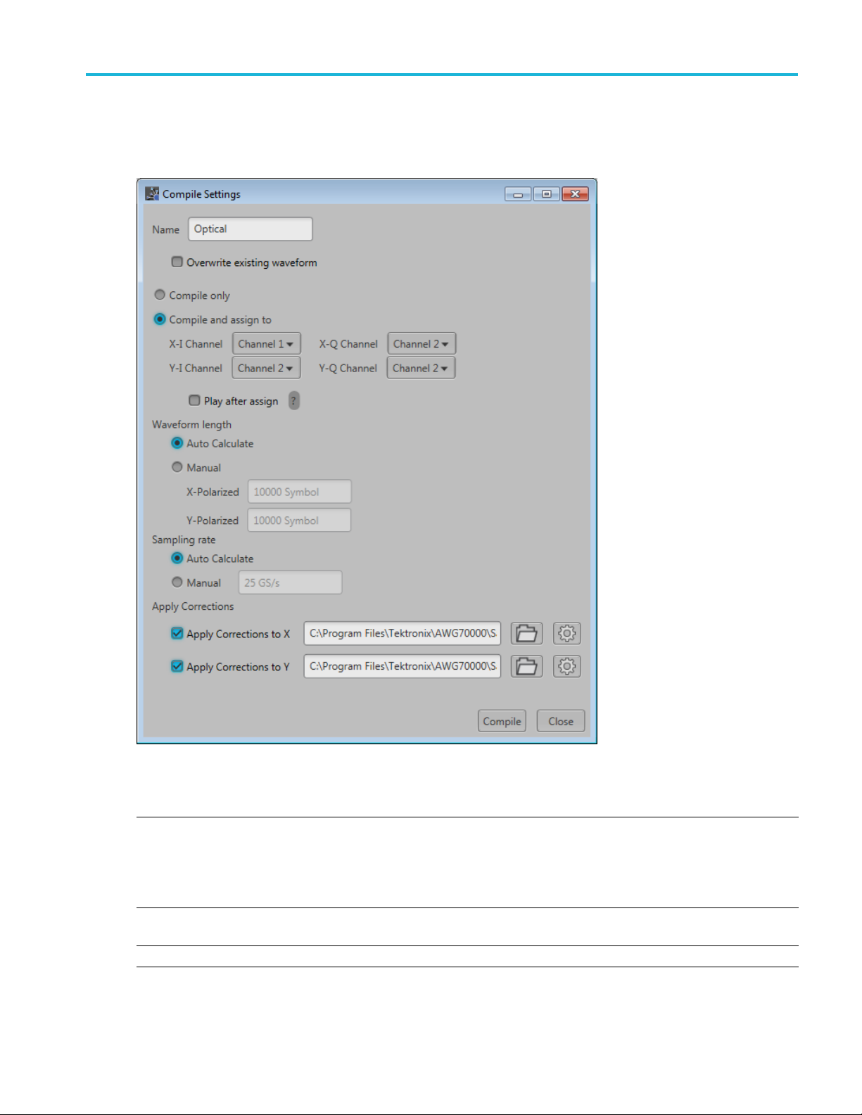
Compile settings
Item Description
Name
Overwrite e xisting
waveform
Compile only The compiled waveforms are simply entered into the Waveforms list.
The application provides a base name for compiled waveforms. You can edit the field
with a name of your choice. The waveform is added to the Waveforms list. If the name
already exists, the name is incremented with a numerical value (unless the overwrite
option is selected).
The Reset Plug-in button resets the Name field to the default name.
If checked, a waveform with the same name (in the waveforms list) is overwritten with no
warnings.
Optical Signal Printable Help Document 7

Orientation Compile settings
Item Description
Compile and assign The compiled waveforms are entered into the Waveforms list and automatically assigned
to a selected c
Play after ass
ign
If checked, th
The instrument’s sample rate and amplitude will change based on the compiled waveform’s
properties.
Waveform length
Auto Calculate This is the default method to set the waveform length. The application creates a waveform
length base
Manual
Select to d
Directly enter the waveform length of the compiled waveform. The length is defined as
number of Symbols.
Sampling Rate
Auto Calculate This is the default method to set the sampling rate. The application creates a sampling
rate bas
Manual
Apply C
orrections
Select t
You can
You can apply corrections to either the X or Y polarizations or both.
Correction file Path: When applying a correction file, navigate to the location of the file.
hannel.
e waveform starts to play out immediately after compiling.
d on the settings chosen for the waveform.
efine a specific waveform l ength.
ed on the settings chosen for the waveform.
o enter a specific sampling rate.
apply a correction file directly to the waveform when compiling.
Use the browse folder icon
avalidfile path is entered, the Correction Settings icon
Once
to navigate to a saved correction file.
is enabled. Select to
display the Frequency Response screen.
Compile Compiles the w avefor m.
xxx
Correction file frequency response
applying an RF correction file, the Frequency Response screen shows plot information and provides
If
Advanced options to apply a Gaussian filter and remove Sin(x)/x distortions.
8 Optical Signal Printable Help Document

Orientation Compile settings
If applying an I/Q correction file (to a pair of I and Q waveforms), the Frequency Response screen shows
plot information and provides Advanced options to apply a skew.
Optical Signal Printable Help Document 9

Orientation Reset Plug-in button
Reset Plug-in button
Returns all plug-in settings to their default values.
Help button
Help button: Provides links where you can obtain additional product help and documentation.
Item Description
User manual
About ...
xxx
Opens the plug-in help system.
Provides you with information about your plug-in application. This information is
helpful when contacting Tektronix about your application.
10 Optical Signal Printable Help Document

Setup tab Setup tab
Setup tab
The setup tab provides all the basic parameters to generate the waveform.
Refer to the following sections about the waveform setup.
Basic Setup parameters (see page 11)
Modulation parameters (see page 12)
Filter parameters (see page 17)
X Data Source parameters (see page 18)
Y Data Source parameters (see page 18)
Basic Setup parameters
The following settings in the Setup tab define the b asic waveform parameters.
Optical Signal Printable Help Document 11

Setup tab Modulation parameters
Item Description
Mode Use the Mode se
Polarization is the direction in which the signal oscillates as it propagates through space
In the case of Optical signals, it oscillates in two distinct directions, the horizontal axis 'X' is
X-Polarizat
Single
Polarization (X)
Dual Polarization
(X&Y)
Baud Rate
X Baseband Offset The baseband offset can be used to provide a frequency offset from 0 (or baseband) for the X
Y Baseba
xxx
nd Offset
Select to cre
Depending on the Modulation selection, selecting Single Polarization generates either one or
two X-Polarized waveforms.
Select to create both X-Polarized signals. and Y-Polarized signals.
Depending
X-Polarized waveforms and one or two Y-Polarized waveforms
Set the baud rate of the compiled waveforms.
The range is dependent on the selected instrument minimum and maximum sampling rate.
d signal.
polarize
The base
polarized signal.
Enabled when Mode is set to Dual Polarization.
lection to set the polarization.
ion and the orthogonal vertical axis 'Y' is the Y-Polarization.
ate single X-Polarized signals.
on the Modulation selection, selecting Dual Polarization generates either one or two
band offset can be used to provide a frequency offset from 0 (or baseband) for the Y
Modul
ation parameters
The Mo
provides a pull-down list to select from the available modulation types. Custom Modulation provides the
ability to create specific modulation parameters.
dulation section provides two methods of defining the digital modulation. Predefined Modulation
12 Optical Signal Printable Help Document
Setup tab Modulation parameters
Predefined Modulation
Item Description
Predefined
Modulation
Digital modu
types
lation
Select a modulation type from the pull-down list. Some modulation types have additional
parameters that are displayed upon selection. B elow are descriptions of the various additional
parameters.
See Symbol Mapping
(see page 29) for values of the modulations.
PSK
BPSK, QPSK, OQPSK
QAM
8 QAM, 16 QAM, 32 QAM, 64 QAM, 128 QAM, 256 QAM, 512 QAM, 1024 QAM
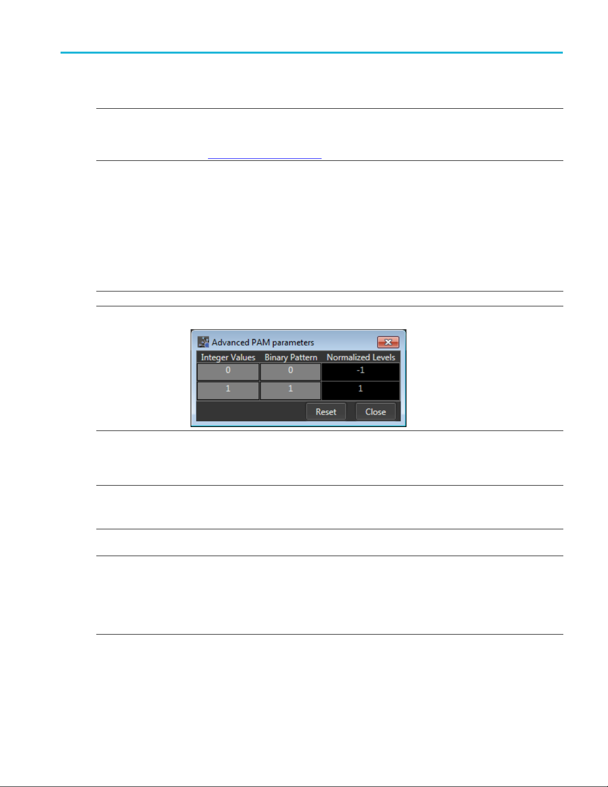
PAM
2PAM,4PAM
,8PAM
PAM selection displays A dvanced... button to set advanced PAM parameters. See below.
OOK
NRZ
Advanced PAM param eters
The Advanced PAM parameters dialog screen allo ws you to further set the Normalized values
for each
PAM level.
xxx
Custom Modulation
Item Desc
Modulation mode
Offset modulation Indicates whether to apply offset modulation or not: Yes, No. Selecting Yes applies offset
dpredefined
Ad
symbols
ription
ct the modulation mode:
Sele
Normal
Differential
ulation.
mod
ovides a dropdown list of modulation types to pre-populate the symbol table. There are three
Pr
choices: BPSK, QPSK, and Circle/Rectangle.
When selecting BPSK or QPSK, a set of default values are placed in the symbol table. Each
bsequent selection (of either) adds and additional set of values.
su
When selecting Circle/Rectangle... , the Add Circle/Rectangle constellation dialog box is displayed
to create a unique symbol map.
Optical Signal Printable Help Document 13

Setup tab Modulation parameters
Item Description
Use the Add Circle/Rectangle constellation dialog box to create a symbol map.
circular or rectangular constellation (or a combination).
Advanced...
You can create
Circle
Select Circle to define a constellation window that allows you to create equally spaced symbols in
acircleofaspecified radius. You can define an offset angle to rotate the constellation.
Symbol Count: Enter number of symbols (2 to 512) to create the constellation.
Radius: Enter the radius (–5 to 5) of the circle.
Phase Offset: Enter a phase offset (–180° to +180°) to rotate the constellation.
Rectangle
Select Rectangular to define constellation points which ar e distributed in a rectangular shape,
akin to QAM modulations.
Symbol Count: Enter number of symbols (4 to 512, in powers of 2) to create the constellation.
Select Advanced... to display the Modify Map dialog screen.
Adjust Offset, Scale, and Phase for I and Q.
odifications are applied to all Bit Values currently in the Symbol table.
The m
14 Optical Signal Printable Help Document

Setup tab Modulation parameters
Item Description
Symbol table editing Use the Symbol table to edit the values in a c ell. Double-click a cell to enter the edit mode for
the cell.
I component: Specify the I component of the modulation. Range: –141.421 to 141.421.
Q component : Specify the Q component of the modulation. Range: –141.421 to 141.421.
Magnitude: S
Phase: Specify the phase of the modulation. Range: –180° to +180°
The Magnitude and Phase parameters depend on the value of the I and Q components. If you
change the va
and updated. Similarly, if you change the M agnitude and Phase values, the values of the I and
Q components are recalculated and updated.
pecify the magnitude of the modulation. Range: 0 to 141.421.
lue of the I and Q components, the M agnitude and Phase v alues are recalculated
Optical Signal Printable Help Document 15

Setup tab Modulation parameters
Item Description
To manage entire rows within the Symbol table, right-click on a row to display the editor m enu.
(Select multi
Add: Adds a single empty row to the end of the table.
Insert: Inserts a single empty row above the currently selected row.
Remove: R emoves the selected rows. (The row must be selected from the Bit Value column.)
Remove All: Deletes then entire contents of the table.
Copy and Paste in the Symbol table
You can copy and paste entire rows within the Symbol table using Ctrl-c (copy) and Ctrl-v (paste)
keys.
• Highlight the rows (or contiguous rows) you wish to copy and press Ctrl-c.
• Highlight the row where you want paste the row or rows and press Ctrl-v.
Copy and Paste Using Excel
You can also copy and paste data from the Symbol table an Excel spreadsheet.
You can also copy data from an Excel spreadsheet into the Symbol table. Ensure that the data in
the Excel spreadsheet is formatted properly to match the Symbol table columns.
xxx
ple rows by holding down the mouse key and sliding to select contiguous rows.)
16 Optical Signal Printable Help Document

Setup tab Filter parameters
Filter parameters
Item Description
Filter
Alpha/B*T Enabled for Raised Cosine and Root Raised Cosine filters.
ution Length
Convol
xxx
Select the filter Type from the following options: Raised Cosine, Root Raised Cosine, Rectangular,
and User Defined.
User Defined
Selecting User Defined provides a filename dialog box to enter a path to a user defined filter file (or
use the folder icon to browse to a filter file).
A filter file a
containing Samples to be considered per symbol followed by filter coefficients.
For example:
Alpha de
Enter the convolution length.
Convol
llows users to provide the filter coefficients. The file should have header information
SamplesPer
ution length defi nes the number of symbols to consider for creating filter taps.
Symbol = 50
-0.000007
-0.000014
-0.000021
-0.000028
-0.000034
-0.00004
-0.000048
....
1
fines the rolls of the filters to smooth the data.
Optical Signal Printable Help Document 17

Setup tab X Data Source parameters
X Data Source parameters
Item Description
Single data source Select a data source to be used for all X Data bits.
Pattern
All One Sends a sequence of binary 1 symbols.
All Zero
File
PRBS Select the PRBS type from the following: 7, 9, 15, 16, 20, 21, 23, 29, 31, and User Defined.
Select the data source:
Sends a sequence of binary 0 symbols.
Select the base data file to be used by entering the path or browsing to the file. The supported
formats are .txt.
Pattern
Data source for
each bit
Define Data
..
bits.
xxx
To edit th
display the PRBS Editor
Enter a pattern of 0s and 1s up to a maximum of 256 digits in the text field that appears.
Select a data pattern that is unique to each bit.
Displays the dialog screen to select the data sources for each bit.
The
The selections available for each bit are the same available as described for the Single data
source selection.
e bit sequence, select User Defined. This displays the PRBS Editor icon
(see page 19) dialog screen.
selected modulation type determines the number of bits presented in the dialog screen.
. Select to
Data Source parameters
Y
Data Source is only available when the polarization mode is set to Dual Polarization (X & Y).
Y
The Y Data Source has identical parameter selections as the X Data Source. Refer to the X Data Source
parameters for descriptions.
18 Optical Signal Printable Help Document
Setup tab PRBS Editor
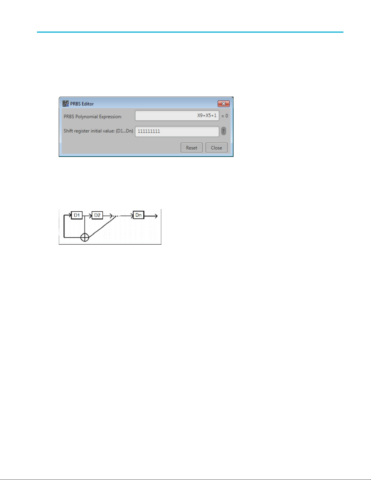
PRBS Editor
This dialog box is displayed when clicking PRBS Editor icon when PRBS is set to User DefinedintheX
or Y Data field(Setuptab).
PRBS sequ
length of the generating shift register. For instance, a shift register with 16 memory cells is required to
generate a PRBS 16 sequence. The pseudo-random sequence of a PRBS generator is determined by the
number of registers and the feedback.
ences are generated by a feedback shift register. The number (#) following PRBS indicates the
Optical Signal Printable Help Document 19

Setup tab PRBS Editor
20 Optical Signal Printable Help Document

IQ Impairments IQ Impairments
IQ Impairments
Item Description
Swap I & Q Select to interchange I and Q signal outputs.
Carrier Leakage
Turn on
IQ Offset Adds equal offset to I and Q signals based on the dB value provided.
IOffset
QOffset
Nonlinear Distortions
n
Turn o
AM/AM k2: Enter the 2nd order coefficient for the magnitude (dB).
PM
AM/
Quadrature Error
non
Tur
I/Q Error Enter the phase angle between the I and Q signals. Range: –30° to +30°.
IQ Imbalance
rn on
Tu
mbalance
I
xxx
Select to add carrier leakage (I and Q) impairments to the carrier.
Adjust the percentage of offset for I and Q based on the IQ Offset dB value.
Select to add nonlinear distortions to the carrier.
k3: Enter the third order coefficient for the magnitude (dB).
ge: –3 dB to +3 dB.
Ran
Enter the 2nd order coefficient for the phase (degrees).
k2:
k3: Enter the third order coefficient for the phase (degrees).
Select to add quadrature error to the carrier.
Select to add IQ imbalance to the carrier.
Enter the imbalance between the I and Q signals. Range: –30% to 30% (–2.28 dB to 3.1 dB).
Optical Signal Printable Help Document 21

IQ Impairments IQ Impairments
22 Optical Signal Printable Help Document
S-Parameter S-Parameter license
S-Parameter license
A license is required to use the S-Parameter feature.
S-Parameters is available when a license is detected by the application. With the license installed on the
host PC where SourceXpress is installed, S-Parameters is available regardless of connecting to a virtual
generator or a real instrument.
Refer to Licensing
S-Parameter
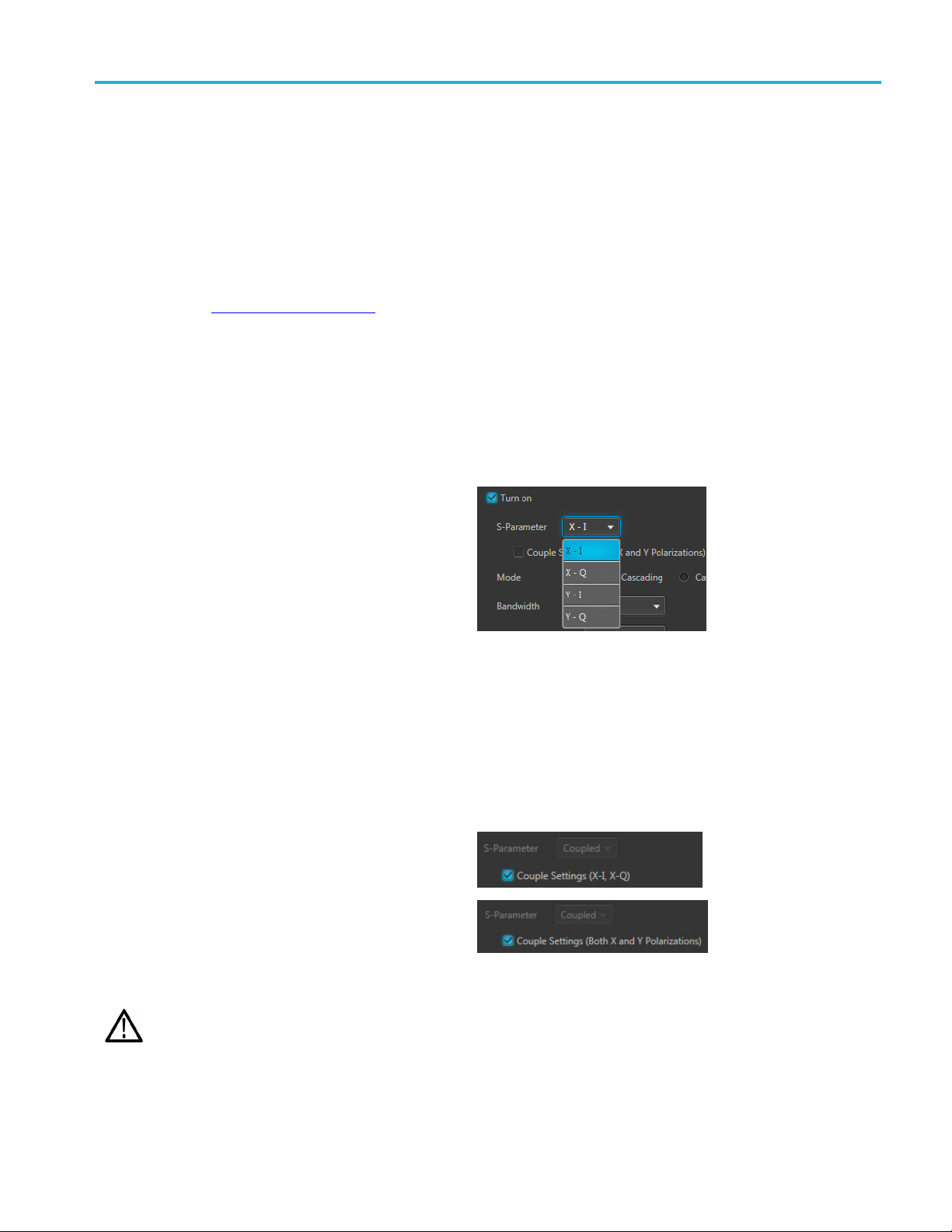
Select Turn on to enable adding S-Parameters to the compiled waveforms.
Select the waveform(s) to apply S-Parameters
S-Parameters a re applied to each compiled
waveform. The available w aveforms depends on the
Mode and the Modulation selections.
When the Mode is set to Single Polarization, you can
apply S-Parameters to the X plane.
When the Mode is set to Dual Polarization, you can
apply S-Parameters to both the X and Y planes.
The Modulation setting determines I and Q choices.
■ Single polarization mode:
Modulation set to PAM or NRZ: S-Parameter choice is X. (Couple S-Parameters is disabled.)
Modulation set to QAM or PSK: S-Parameter choices are X-I and X-Q.
■ Dual polarization mode:
Modulation set to PAM or N RZ: S-Parameter choices are X and Y.
Modulation is set to QAM or PSK: S-Parameter choices are X-I, X-Q, Y-I, and Y-Q.
Couple Settings
You can apply S-Parameters to the each available
waveform or apply the same S-Parameters all
waveforms. The couple settings action changes
depending on the Mode and Modulation settings.
In the cases where only one waveform is generated,
the Couple Settings selection is not available.
(see page 31) for information about obtaining a license file.
NOTE. This is a sample of the S-Parameter pull-down menu.
In the case where I and Q waveforms are generated, the I (or X-I) waveform S-Parameters are applied to all waveforms. In
the case where X and Y waveforms are generated, the X waveform S-Parameters are applied to the Y waveform.
CAUTION. When initially selecting Couple Settings, parameters are instantly replaced.
xxx
Optical Signal Printable Help Document 23
S-Parameter S-Parameter
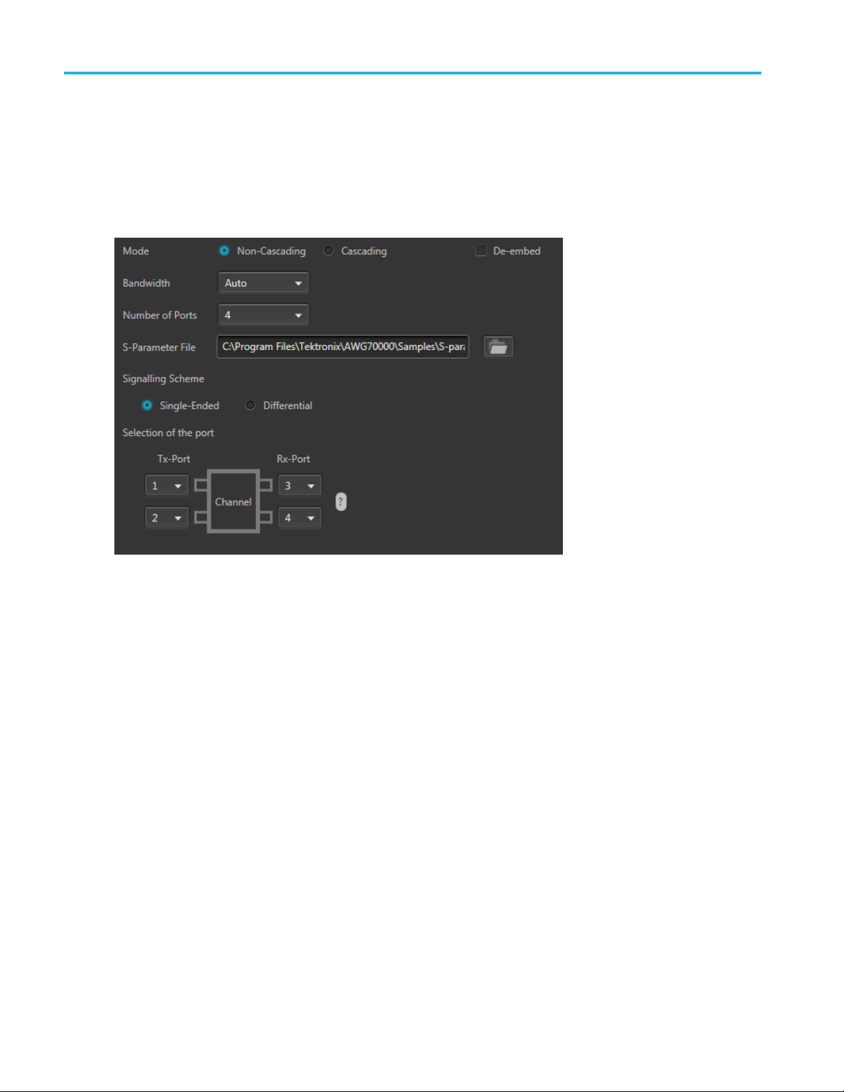
S-Parameter parameters
Below is a sample S-Parameter dialog screen with the Number of Ports set to 4. The dialog screen changes
to accommodate the Number of Ports selected.
The available S-Parameter settings are identical regardless of the selected waveform.
The information p rovided for S-Parameters applies to both the Non-Cascading and Cascading modes.
24 Optical Signal Printable Help Document
S-Parameter S-Parameter
Item Description
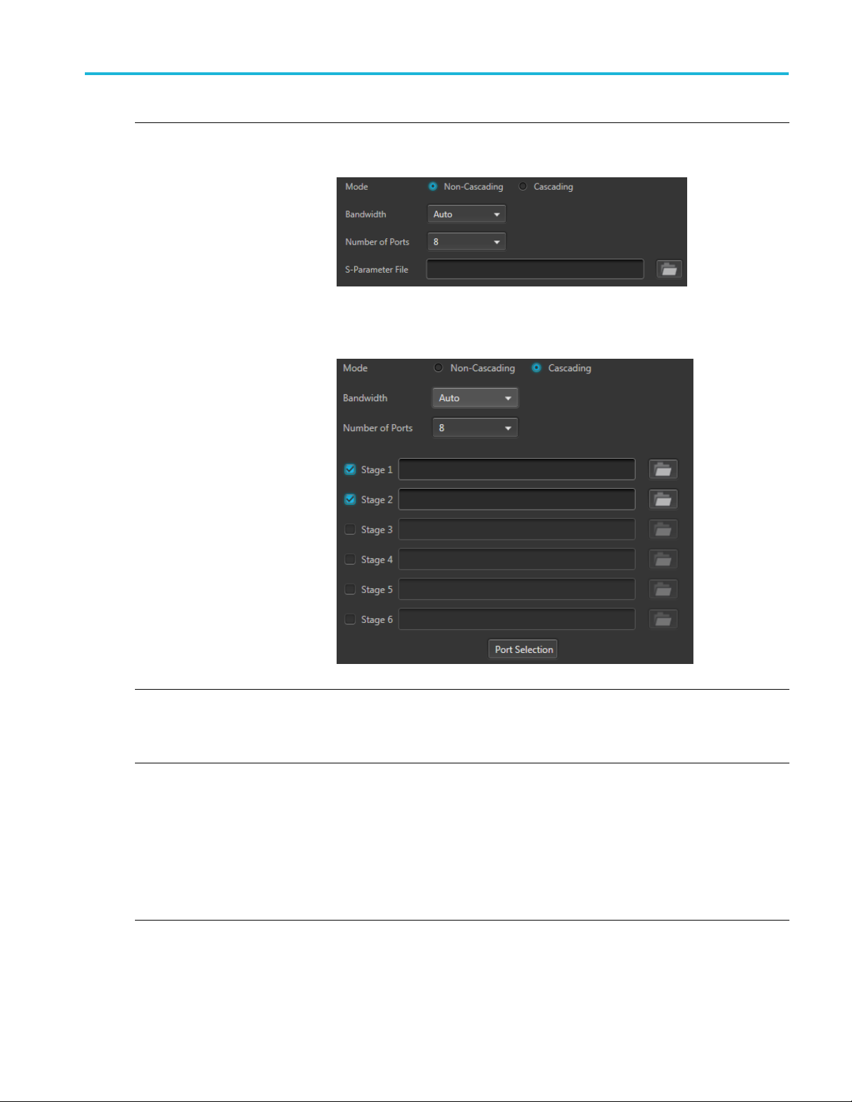
Mode
Select Non-Cascading or Cascading S-parameter mode.
In the Non-Cas
from only one S -parameter file.
In the Cascading mode, you can cascade up to six S-parameter files in Stages and
apply the characteristics on the signal. You can select the files to apply by turning on
or turning off the corresponding Stages shown in the display. All the selected fi les
should be of the same type. The settings depend on the selected type of file.
cading mode, you apply S-parameter characteristics on the signal
The files supported are s1p, s2p, s4p, s6p, s8p, and s12p.
De-embed
(Non-Cascading mode)
Cascading De-embed
(Cascading mode)
Bandwidth
Check the box to invert the S-Parameters from the signal. This removes the effects
of the component (for which the S-Parameters w ere created) from the signal path.
Auto – The bandwidth is defined at the point where the signal rolls off to -60 dB. If
this results in a bandwidth greater than the instrument supports, the bandwidth is set
to ½ of the waveform’s sample rate (i.e. Nyquist Frequency).
Full Bandwidth – The bandwidth is set to ½ of the waveform’s sample rate (i.e.
Nyquist Frequency).
Manual – The bandwidth can set by the user from 1 Hz to ½ of the maximum sample
rate of the instrument. If the set Bandwidth is greater than the Nyquist (Sample rate
of the waveform/2), then the software limits the bandwidth to ½ of the waveform’s
sample rate. A warning message is provided.
Optical Signal Printable Help Document 25

S-Parameter S-Parameter
Item Description
Number of Ports Choose the number of ports. The port matrixes supported are 1, 2, 4, 6, 8, and 12.
The number of p
• The type of S-P arameter file to apply
• The Signaling Scheme choice
• The port mat
S-Parameter
Signaling
(Only for 4, 8, and 12 ports)
Selection of the port
(No port s
environments)
Victim
Aggress
(Only for 8 and 12 ports)
Port Selection The Port Selection button is available only when in Cascading mode. Press the
File
Scheme
election for 1 Port
or and Both
Navigate to t
that you are able to open is dependent on the number of ports selected. For instance,
only .s4p files can be opened if the Number of Ports is set to 4.
The files sup
Single-En
the file to physical locations in your link.
Differential: If the data is differential, you m ust select the data layout in the file.
Use the diagrams to map the ports for the transmitter ports (Tx-Port) and the receiver
ports (Rx
When choosing the number of Ports, you are presented with an active diagram of
the ports. The diagram presented reflects the Number of Ports selected and the
ng Scheme (if appropriate for the ports selected).
Signali
The default setting with no cross-talk effects.
Victim:
Aggressor: Select this to activate aggressor signal parameters, adding the effect
of cross-talk.
Port Selection button to display an active dialog screen to map the ports for the
itter ports (Tx-Port) and the receiver ports (Rx-Port) for each stage.
transm
orts selected determines:
rixes available
he Touchstone file to apply to the signal. The type of Touchstone files
ported are s1p, s2p, s4p, s6p, s8p, and s12p.
ded: If the data is single-ended, you must map the port numbers as used in
-Port).
xxx
S-Parameter file descriptions
1-port
Files with one port of data contain only one S-parameter file (s1p) so they do not require any further input.
26 Optical Signal Printable Help Document

S-Parameter S-Parameter
2-port
Files with data for two ports contain four S-parameters as a 2x2 matrix. These are Touchstone 2-port files
p). A dialog box is created to define the 2-port mapping.
(s2
4-Port
Files with data for four ports contain 16 S-parameters as a 4x4 matrix. These are Touchstone 4-port files
(s4p). They may contain single-ended or differential data. A dialog box is created to define the 4-port
mapping for either single-ended or differential data.
If the data is single-ended, you must map the port numbers as used in the file to physical locations in
your link.
You can select the port for both transmitter and receiver from the drop-down list. Each drop-down list
has ports from 1 to 2.
If the data is differential, you must select the data layout in the file.
6-port
Files with data for six ports contain 36 S-parameters as a 6x6 matrix. These are Touchstone 6-port files
(s6p). A dialog box is created to define the 6-port mapping.
8-Port
Files with data for eight ports contain 64 S-parameters as an 8x8 matrix. These are Touchstone 8-port files
(s8p). They may contain single-ended or differential data. A dialog box is created to define the 8-port
mapping for either single-ended or differential data.
If the data is single-ended, you must map the port numbers as used in the file to physical locations in
your link.
You can select the port for both transmitter and receiver from the drop-down list. Each drop-down list
has ports from 1 to 4.
If the data is differential, you must select the data layout in the file.
12-Port
Files with data for 12 ports contain 144 S-parameters as an 12x12 matrix. These are Touchstone 12-port
files (s12p). They may contain single-ended or differential data. A dialog box is created to define the
12-port mapping for either single-ended or differential data.
If the data is single-ended, you must map the port numbers as used in the file to physical locations in
your link.
You can select the port for both transmitter and receiver from the drop-down list. Each drop-down list
has ports from 1 to 6.
If the data is differential, you must select the data layout in the file.
Optical Signal Printable Help Document 27

S-Parameter S-Parameter
Aggressor signals
8 and 12 port S-parameters allows you to activate aggressor signal parameters and to add the effect of
cross-talk. 12 port S-parameters allows 2 Aggressor signal parameters.
AggressorscanbeaddedineitherNon-Cascading Mode or Cascading Mode.
The Aggresso
Item Description
Signal Choose the type of aggressor signal with the dropdown list:
Data Rate
Aggressor Amplitude Enter the signal amplitude.
Crosstalk Type Choose the type of crosstalk of the aggressor signal.
xxx
r signal parameters include:
•Clock: Ind
• PBRS: Also choose the number of bits
• File: Indicates that the aggressor signal is another pattern file. Navigate to
the Patter
• Same as victim: The signal flow of the aggressor is same as the victim.
Specify the data rate (in bps) of the signal.
This is not available when the Aggressor signal is set to be the same as the victim.
This is not available when the Aggressor signal is set to be the same as the victim.
• Near-
• Far-End Crosstalk
• Both
icates that the aggressor signal is a clock pattern.
n file
End Crosstalk
28 Optical Signal Printable Help Document

Symbol mapping Symbol mapping
Symbol mapping
The RF Generic Signal plug-in supports many Digital modulation types. Diagrams are available for many
of the more common types to illustrate the Bit mapping of the symbols.
Many of these mapping diagrams are too complex to show within this help system, or from a printed
document. Because of this, the symbol maps are only available by downloading the PDF version of this
help system
The symbol maps are in the form of an Excel spreadsheet that is attac hed to the PDF file.
from the Tektronix web site.
All documentation is available on the Tektronix Web site (www.tek.com/manual/downloads
for the RF Generic Signal User documentation.
). Search
Optical Signal Printable Help Document 29

Symbol mapping Symbol mapping
30 Optical Signal Printable Help Document

Licensing Licensing
Licensing
A license is required for this plug-in to become operational. The plug-in must be licensed for use w ith the
host application from where you want to use the plug-in.
For example, to use the plug-in from SourceXpress, SourceXpress must have a license. To use the plug-in
from an instrument, the instrument must have a license.
Refer to the application help (for either SourceXpress or the AWG70000A series instruments) for complete
information about obtaining and installing license files.
Optical Signal Printable Help Document 31

Licensing Licensing
32 Optical Signal Printable Help Document

Index
Index
A
Aggressor, 28
Apply correc
tions file, 8
C
Carrier leakage, 21
Compile, 6
Compile settings, 7
Correction fi le, 8
frequency response, 8
Couple Se
ttings, 23
D
Digital Modulation setup, 12
Display elements, 5
Documentation, 2
Connected instrument, 2
Optical plug-in, 2
eXpress, 2
Sourc
E
Elements of the display, 5
H
Help menu, 10
I
IQ imbalance, 21
IQ Impairments, 21
carrier leakage, 21
Q imbalance , 21
I
nonlinear distortions, 21
quadrature error, 21
K
Key features, 2
L
Licensing, 31
M
Modulati
on
symbol mapping, 29
N
Nonlinear distortions, 21
O
Optical signal plug-in
description, 1
P
Plug-in selection, 5
S Editor, 19
PRB
Q
Quadrature error, 21
R
Reset Plug-in, 10
S
S-Parameter
file types, 26
S-Parameter license, 23
S-Parameters, 23
Aggressor, 26
Cascading
Couple Settings, 23
De-embed, 25
Differential, 26
Non-Cascading, 25
Number of Ports, 26
Selecti
Signaling Scheme, 26
Single-Ended, 26
Victim, 26
Service s upport, 3
Setup, 11
ort information, 3
Supp
Symbol mapping, 29
,25
on of the port, 26
T
Technical support, 3
X
X Data source parameters, 18
Y
Y Data source parameters, 18
Optical Signal Printable Help Document 33
 Loading...