


OM5110
xx
ZZZ
46 GBaud Multi-Format Optical Transmitter
User Manual
*P071320300*
071-3203-00


xx
OM5110
ZZZ
46 GBaud Multi-Format Optical Transmitter
User Manual
www.tektronix.com
071-3203-00

Copyright © Tektronix. All rights reserved. Licensed software products are owned by Tektronix or its subsidiaries
or suppliers, and are protected by national copyright laws and international treaty provisions.
Tektronix products are covered by U.S. and foreign patents, issued and pending. Information in this publication
supersedes that in all previously published material. Specifications and price change privileges rese rved.
TEKTRONIX and TEK are registered trademarks of Tektronix, Inc.
MATLAB is a registered trademark of The MathWorks, Inc.
LabVIEW is a trademark of National Instruments, Inc.
Intel and Pentium are registered trademarks of the Intel Corporation.
Other prod
uct and company names listed are trademarks and trade names of their respective companies.
Contacting Tektronix
Tektronix, Inc.
14150 SW
P.O . B o x 5 00
Beaverton, OR 97077
USA
For product information, sales, service, and technical support:
In Nor
Worl d wide, vis it www.tektronix.com to find contacts in your area.
Karl Braun Drive
th America, call 1-800-833-9200.

Warranty
Tektronix warrants that this product will be free from defects in materials and workmanship for a period of one (1)
year from the date of shipment. If any such product proves defective during this warranty period, Tektronix, at its
option, either will repair the defective product without charge for parts and labor, or will provide a replacement
in exchange for the defective product. Parts , modules and replacement products used by Tektronix for warranty
work may be n
the property of Tektronix.
ew or reconditioned to like new performance. All replaced parts, modules and products become
In order to o
the warranty period and make suitable arrangements for the performance of service. Customer shall be responsible
for packaging and shipping the defective product to the service center designated by Tektronix, with shipping
charges prepaid. Tektronix shall pay for the return of the product to Customer if the shipment is to a location within
the country in which the Tektronix service center is located. Customer shall be responsible for paying all shipping
charges, duties, taxes, and any other charges for products returned to any other locations.
This warranty shall not apply to any defect, failure or damage caused by improper use or improper or inadequate
maintenance and care. Tektronix shall not be obligated to furnish service under this warranty a) to repair damage
result
b) to repair damage resulting from improper use or connection to incompatible equipment; c) to repair any damage
or malfunction caused by the use of non-Tektronix supplies; or d) to service a product that has been modified or
integrated with other products when the effect of such modification or integration increases the time or difficulty
of servicing the product.
THIS WARRANTY IS GIVEN BY TEKTRONIX WITH RESPECT TO THE PRODUCT IN LIEU OF ANY
OTHER WARRANTIES, EXPRESS OR IMPLIED. TEKTRONIX AND ITS VENDORS DISCLAIM ANY
IMPLIED WARRANTIES OF MERCHANTABILITY OR FITNESS FOR A PARTICULAR PURPOSE.
TRONIX' RESPONSIBILITY TO REPAIR OR REPLACE DEFECTIVE PRODUCTS IS THE SOLE
TEK
AND EXCLUSIVE REMEDY PROVIDED TO THE CUSTOMER FOR BREACH OF THIS WARRANTY.
TEKTRONIX AND ITS VENDORS WILL NOT BE LIABLE FOR ANY INDIRECT, SPECIAL, INCIDENTAL,
OR CONSEQUENTIAL DAMAGES IRRESPECTIVE OF WHETHER TEKTRONIX OR THE VENDOR HAS
ADVANCE NOTICE OF THE POSSIBILITY OF SUCH DAMAGES.
[W2 – 15AUG04]
btain service under this warranty, Customer must notify Tektronix of the defect before the expiration of
ing from attempts by personnel other than Tektronix representatives to install, repair or service the product;


Table of Contents
Important safety information ........... .................................. ................................ ........ iv
General safety summary ..................................................................................... iv
Service safety summary.................. .................................. ................................ .. vi
Terms in this manual ....................... ................................ ................................. vii
Symbols and terms on the product ......................................................................... vii
Compliance information ........................................................................................... x
EMC compliance ....... .................................. ................................ ..................... x
Safety compliance ............................................................................................ xi
Environmental considerations.............................................................................. xiii
Preface .............................................................................................................. xv
Supported products ........................................................................................... xv
About this manual ............................................................................................ xv
Getting started.. ... . .. . ... ... . .. . ... ... ... . ... ... ... . ... ... ... . ... ... ... . ... ... ... . . .. . ... ... ... . ... ... ... . ... ... ... . 1
Product description ....... ................................ ................................ ..................... 1
Accessories ..................................................................................................... 2
Options.......................................................................................................... 2
First product inspection ....................................................................................... 3
Environmental operating requirements............................... ................................ ....... 4
Power requirements..................... .................................. ................................ ..... 4
PC requirements .................... ................................ .................................. ......... 5
Software installation........................................................................................... 6
Set the instrument IP address................................................................................. 8
Operating basics ................. .................................. ................................ ................ 13
OM5110 controls and connectors ........................................................................... 13
Connect the power cable ..................... ................................ ................................ 14
Power on the instrument ..................................................................................... 15
Theory of operation........................................... .................................. .............. 15
Equipment setup ........ ................................ ................................ ...................... 17
Software overview............................................................................................ 18
Appendix A: The automated test equipment (ATE) interface .............................. .................. 25
The LRCP ATE interface .................. .................................. ................................ 25
ATE functionality in MATLAB .. ... . ... ... . ... ... . ... ... . .. . ... ... . ... ... . ... ... . ... ... .. .. . ... ... . ... ... . . 37
Appendix B: Cleaning and maintenance.......... ................................ .............................. 39
Cleaning ....................................................................................................... 39
Maintenance................. ................................ ................................ .................. 39
Index
OM5110 User Manual i

Table of Contents
List of Figure
Figure 1: IP address setup (LRCP) ............................................................................... 8
Figure 2: OM
Figure 3: OM5110 rear panel .................................................................................... 14
Figure 4: OM5110 block diagram ............................................................................... 16
Figure 5: OM5110 connection diagram......................................................................... 17
Figure 6: OM5110 controls (LRCP)....................................... ................................ ...... 18
5110 front panel ....... ................................ ................................ ............ 13
s
ii OM5110 User Manual

List of Tables
Table 1: Standard and optional accessories...................................................................... 2
Table 2: OM5
Table 3: OM5110 environmental requirements .............. .................................. ................. 4
Table 4: AC line power requirements ............................................................................ 4
Table 5: Software install: controller d evice (PC or oscilloscope). . .. . ... ... . ... ... . ... ... . ... ... . . .. . ... ... . . 7
Table 6: OM5110 Laser controls (LRCP) ...................................................................... 20
Table 7: OM5110 Modulator controls (Auto-Set mode) (LRCP) ............................................ 21
Table 8: O
Table 9: OM5110 Driver Amp controls (LRCP)......................... ................................ ...... 24
110 options.......................................................................................... 2
M5110 Modulator controls (manual mode) (LRCP) .... ................................ .......... 22
Table of Contents
OM5110 User Manual iii

Important safety information
Important saf
ety information
This manual c
for safe operation and to keep the product in a safe condition.
To safely perform service on this product, additional information is provided at
the end of this section. (See page vi, Servicesafetysummary.)
General safety summary
Use the product only as specified. Review the following safety precautions to
avoid injury and prevent damage to this product or any products connected to it.
Carefully read all instructions. Retain these instructions for future reference.
Comply with local and national safety codes.
For correct and safe operation of the product, it is essential that you follow
generally accepted safety procedures in addition to the safety precautions specified
in this manual.
The product is designed to be used by trained personnel only.
Only qualified personnel who are aware of the hazards involved should remove
the cover for repair, maintenance, or adjustment.
ontains information and warnings that must be followed by the user
To avoid fire or personal
injury
Before use, always check the product with a known source to be sure it is
operating correctly.
This product is not intended for detection of hazardous voltages.
Use personal protective equipment to prevent shock and arc blast injury where
hazardous live conductors are exposed.
When incorporating this equipment into a system, the safety of that system is the
responsibility of the assembler of the system.
Use proper power cord. Use only the power cord specified for this product and
certified for the country of use.
Do not use the provided power cord for other products.
Ground the product. This product is grounded through the grounding conductor
of the power cord. To avoid electric shock, the grounding conductor must be
connected to earth ground. Before making connections to the input or output
terminals of the product, make sure that the product is properly
Do not disable the power cord grounding connection.
Power disconnect. The power cord disconnects the product from the power
source. See instructions for the location. Do not position the equipment so that it
grounded.
iv OM5110 User Manual

Important safety information
is difficult to d
all times to allow for quick disconnection if needed.
Observe all terminal ratings. To av o i d fire or shock hazard, observe all ratings
and markings on the product. Consult the product manual for further ratings
information before making connections to the product.
Do not apply a potential to any terminal, including the common terminal, that
exceeds the maximum rating of that terminal.
Do not float the common terminal above the rated voltage for that terminal.
The measuring terminals on this product are not rated for connection to mains or
Category II, III, or IV circuits.
Do not operate without covers. Do not o perate this product with covers or panels
removed, or with the case open. Hazardous voltage exposure is possible.
Avoid exposed circuitry. Do not touch exposed connections and components
when power is present.
Do not operate with suspected failures. If you suspect tha
product, have it inspected by qualified service personnel.
Disable the product if it is damaged. Do not use the product if it is damaged
or operates incorrectly. If in doubt about safety of the product, turn it off and
disconnect the power cord. Clearly mark the product to prevent its further
operation.
isconnect the power cord; it must remain accessible to the user at
t there is damage to this
Examine the exterior of the product before you use it. Look for cracks or missing
pieces.
Use only specified replacement parts.
Replace batteries properly. Replace batteries only with the specified type and
rating.
Use proper fuse. Use only the fuse type and rating specified for this product.
Wear eye protection. Wear eye protection if exposure to high-intensity rays or
laser radiation exists.
Do not operate in wet/damp conditions. Be aware that condensation may occur if
a unit is moved from a cold to a warm e nvironment.
Do not operate in an explosive atmosphere.
Keep product surfaces clean and dry. Remove the input signals before you clean
the product.
Provide proper ventilation. Refer to the installation instructions in the manual for
details on installing the product so it has proper ventilation.
OM5110 User Manual v

Important safety information
Servi
ce safety summary
Slots and openi
otherwise obstructed. Do not push objects into any of the openings.
Provide a safe working environment. Always place the product in a location
convenient for v iewing the display and indicators.
Avoid improper or prolonged use of keyboards, pointers, and button pads.
Improper or prolonged keyboard or pointer use may result in serious injury.
Be sure your work area meets applicable ergonomic standards. Consult with an
ergonomics professional to avoid stress injuries.
Use care when lifting and carrying the product.
Warning- Use correct controls and procedure. Use of controls, adjustments, or
procedu
radiation exposure.
Do not directly view laser output. Under no circumstances should you use any
optical instruments to view the laser output directly.
res other than those listed in this document may result in hazardous
ngs are provided for ventilation and should never be covered or
The Service safety summary section contains additional information required to
safely perform service on the product. Only qualified personnel should perform
ice procedures. Read this Service safety summary and the G eneral safety
serv
summary before performing any service procedures.
To avoid electric shock. Do not touch exposed connections.
Do not service alone. Do not perform internal service or adjustments of this
oduct unless another person capable of rendering first aid and resuscitation is
pr
present.
Disconnect power. To avoid electric shock, switch off the product power and
disconnect the power cord from the mains power before removing any covers or
panels, or opening the case for servicing.
Use care when servicing with power on. Dangerous voltages or currents may exist
in this product. Disconnect power, remove battery (if applicable), and disconnect
test leads before removing protective panels, soldering, or replacing components.
Verify safety after repair. Always recheck ground continuity and mains dielectric
strength after performing a repair.
vi OM5110 User Manual
Terms in this manual
These terms may appear in this manual:
WAR N ING. Warning statements identify conditions or practices that could result
in injury or loss of life.
CAUTION. Caution statements identify conditions or practices that could result in
damage to this product or other property.
Symbols and terms on the product
Important safety information
These ter
The following symbol(s) may appear on the product:
ms may appear on the product:
DANGER indicates an injury hazard immediately accessible as you read
the mark
WARNING indicates an injury hazard not immediately accessible as you
read th
CAUTION indicates a hazard to property including the product.
ing.
emarking.
When this symbol is marked on the product, be sure to consult the manual
to find out the nature of the potential hazards and any actions which have to
be taken to avoid them. (This symbol may also be used to refer the user to
ratings in the manual.)
OM5110 User Manual vii

Important safety information
Front panel lab
els
Item Description
1
Indicates the location of laser apertures
2
viii OM5110 User Manual

Important safety information
Rear panel labe
ls
Item Description
1 Instrument model and serial number label
2
3
Fuse safety information
COMPLIES WITH 21CFR1040.10 EXCEPT
FOR DEVIATIONS PURSUANT TO LASER
NOTICE NO. 50, DATED JUNE 24, 2007
OM5110 User Manual ix

Compliance information
Compliance in
EMC compliance
EC Declaration of
Conformity – EMC
formation
This section
environmental standards with which the instrument complies.
Meets intent of Directive 2004/108/EC for Electromagnetic Compatibility.
Compliance was demonstrated to the following specifications as listed in the
Official Journal of the European Communities:
EN 61326-1 2006. EMC requirements for electrical equipment for measurement,
control
CISPR 11:2003. Radiated and conducted emissions, Group 1, Class A
IEC 61000-4-2:2001. Electrostatic discharge immunity
IEC 61000-4-3:2002. RF electromagnetic field immunity
IEC 61000-4-4:2004. Electrical fast transient / burst immunity
IEC 61000-4-5:2001. Power line surge immunity
lists the EMC (electromagnetic compliance), safety, and
, and laboratory use.
123
1000-4-6:2003. Conducted RF immunity
IEC 6
IEC 61000-4-11:2004. Voltage dips and interruptions immunity
EN 61000-3-2:2006. AC power line harmonic emissions
EN 61000-3-3:1995. Voltage changes, fluctuations, and flicker
European contact.
ektronix UK, Ltd.
T
Western Peninsula
Western Road
Bracknell, RG12 1RF
United Kingdom
1
This product is intended for use in nonresidential areas only. Use in residential areas may cause electromagnetic
interference.
2
Emissions which exceed the levels required by this standard may occur when this equipment is connected to a
test object.
3
For compliance with the EMC standards listed here, high quality shielded interface cables should be used.
x OM5110 User Manual

Compliance information
Australia / New Zealand
Declaration of
Conformity – EMC
Safety complianc
EU declaration of
conformity – low voltage
Complies with t
following standard, in accordance with ACMA:
CISPR 11:2003. Radiated and Conducted Emissions, Group 1, Class A, in
accordance with EN 61326-1:2006.
Australia / New Zealand contact.
Baker & McKenzie
Level 27, AMP Centre
50 Bridge Street
Sydney NSW 2000, Australia
he EMC provision of the R adiocommunications Act per the
e
This section lists the safety standards with which the product complies and other
safety compliance information.
Compliance was demonstrated to the following specification as listed in the
Official Journal of the European Union:
Low Voltage Directive 2006/95/EC.
EN 61010-1. Safety Requirements for Electrical Equipment for Measurement,
Control, and Laboratory Use – Part 1: General Requirements.
U.S. nationally recognized
testing laboratory listing
Canadian certification
Additional compliances
Equipment type
EN 60825-1. Safety of Laser Products - Part 1: Equipment classification
and requirements.
UL 61010-1. Safety Requirements for Electrical Equipment for Measurement,
Control, and Laboratory Use – Part 1: General Requirements.
CAN/CSA-C22.2 No. 61010-1. Safety Requirements for Electrical
Equipment for Measurement, Control, and Laboratory Use – Part 1: General
Requirements.
IEC 61010-1. Safety Requirements for Electrical Equipment for
Measurement, Control, and Laboratory Use – Part 1: General Requirements.
IEC 60825-1. Safety of Laser Products - Part 1: Equipment classification
and requirements.
This laser product complies with 21CFR1040.10 except for deviations
pursuant to Laser Notice No. 50, dated June 24, 2007.
Test and measuring equipment.
OM5110 User Manual xi

Compliance information
Safety class
Pollution degree
descriptions
Class 1 – ground
A measure of the contaminants that could occur in the environment around
and within a product. Typically the internal environment inside a product is
considered to be the same as the external. Products should be used only in the
environment for which they are rated.
Pollution degree 1. No pollution or only dry, nonconductive pollution occurs.
Products in this category are generally encapsulated, hermetically sealed, or
located in clean rooms.
Pollution degree 2. Normally only dry, nonconductive pol
Occasionally a temporary conductivity that is caused by condensation must
be expected. This location is a typical office/home environment. Temporary
condensation occurs only when the product is out of service.
Pollution degree 3. Conductive pollution, or dry, nonconductive pollution
that becomes conductive due to condensation. These are sheltered locations
where neither temperature nor humidity is controlled. The area is protected
from direct sunshine, rain, or direct wind.
Pollution degree 4. Pollution that generates persistent conductivity through
conductive dust, rain, o r snow. Typical outdoor locations.
ed product.
lution occurs.
Pollution degree rating
IP rating
Measurement and
overvoltage category
descriptions
Mains overvoltage
category rating
Pollution degree 2 (as defined in IEC 61010-1). Rated for indoor, dry location
use only.
IP20 (as defined in IEC 60529).
Measurement terminals on this product may be rated for measuring mains voltages
from one or more of the following categories (see specific ratings marked on
the product and in the manual).
Category II. Circuits directly connected to the building wiring at utilization
points (socket outlets and similar points).
Category III. In the building wiring and distribution system.
Category IV. At the source of the electrical supply to the building.
NOTE. Only mains power supply circuits have an overvoltage category rating.
Only measurement circuits have a measurement category rating. Other circuits
within the product do not have either rating.
Overvoltage category II (as defined in IEC 61010-1).
xii OM5110 User Manual

Environmental considerations
This section provides information about the environmental impact of the product.
Compliance information
Product end-of-life
handling
Restriction of hazardous
tances
subs
Observe the f
Equipment recycling. Production of this equipment required the extraction and
use of natural resources. The equipment may contain substances that could be
harmful to the environment or human health if improperly handled at the product’s
end of life. To avoid release of such substances into the environment and to
reduce the
an appropriate system that will ensure that most of the materials are reused or
recycled appropriately.
Perchlorate materials. This product contains one or more type CR lithium
batteries. According to the state of California, CR lithium batteries are
ified as perchlorate materials and require special handling. See
class
www.dtsc.ca.gov/hazardouswaste/perchlorate for additional information.
This product is classified as an industrial monitoring and control instrument,
s not required to comply with the substance restrictions of the recast RoHS
and i
Directive 2011/65/EU until July 22, 2017.
ollowing guidelines when recycling an instrument or component:
use of natural resources, we encourage you to recycle this product in
This symbol indicates that this product complies with the applicable European
Union re
on waste electrical and electronic equipment (WEEE) and batteries. For
information about recycling options, check the Support/Service section of the
Tekt r on
quirements according to Directives 2002/96/EC and 2006/66/EC
ixWebsite(www.tektronix.com).
OM5110 User Manual xiii

Compliance information
xiv OM5110 User Manual

Preface
Preface
Supported products
About this manual
This manual d
Multi-Format Optical Transmitter.
The information in this manual applies to the following Tektronix product:
OM5110 46 G
This manu
Getting started shows you how to install and configure the OM5110 instrument.
Operating basics provides an overview of the front- and rear-panel controls
and connections, and basic operations.
Reference provides further information about specific instrument or software
operation.
escribes how to install and operate the OM5110 46 GBaud
Baud Multi-Format Optical Transmitter
al contains the following sections:
OM5110 User Manual xv

Preface
xvi OM5110 User Manual

Getting started
This section contains the following informationtogetyoustartedusingthe
instrument:
Product description
List of instrument accessories and options
Firstproductinspection
Operating requirements (environmental, power)
Product description
Key features
Software
The OM51
multi-format transmitter that can generate single and dual-polarization optical
signals with BPSK, QPSK, QAM, or arbitrary modulation up to 46 GBaud.
A remote interlock for the laser, located on the rear of the unit, allows for remote
locking of laser output.
Use the OM5110 instrument with a Tektronix OM4000 series Coherent Optical
Signal Analyzer, Tektronix real-time and equivalent-time oscilloscopes, and
coherent signal generators such as Tektronix AWG70001 or PPG3204 instruments,
for a complete, end-to-end coherent optical testing solution.
Baud rate up to 34 GBaud for arbitrary signals in small signal regime < 0.5 V
Baud rate up to 46 GBaud for NRZ bipolar signaling such as BPSK and
QPSK with input amplitude of 1 V
Up
16-QAM modulation; support for other popular modulation formats
, network, and hardware setup
10 46 GBaud Multi-Format Optical Transmitter is a dual-polarization
pp
to four driven electrical inputs to provide 1- and 2-pol BPSK, QPSK, and
pp
ssisted modulation setup using application note and AWG input files
A
Internal C- or L-band laser (option at time of order)
Optical bias is manually or automatically controlled through UI
Amplifier electrical bias is manually or automatically controlled through UI
UI has automatic test interface (ATE)
OM5110 User Manual 1

Getting started
Accessories
The following table lists the standard and optional accessories provided with
the OM5110 instrument.
Table 1: Standard and optional accessories
Tektronix
part
Accessory Std. Opt.
OM5110 46 GBaud Mult-Format Optical Transmitter
OM5110 46 GBaud Mult-Format Optical Transmitter U ser
Manual (this manual)
Software USB flashdrive
Ethernet cable, 7 ft.
RF Cable, 2.92 mm, 9 in. (4 cables)
Shorting cap for BNC interlock connector
Power cord
(See page 3, International power cord options.)
Reply card
Cleaning swab
China RoHS sheet
Patch Cord, Fiber, APC/APC, 8 in.
●
●
●
●
●
●
●
●
●
●
●
number
Varies by
option
071-3203-
650-5730-xx
174-6230-xx
174-6227-xx
131-8925-xx
Varies by
option
Not
orderable
Not
orderable
Not
orderable
174-6231-xx
xx
Options
e the following table to select options to order with the OM5110. See the
Us
46 GBaud Mult-Format Optical Transmitter OM5110 Datasheet (Tektronix
part number 54W-29475-X) for a complete listing of options and recommended
configurations.
Table 2: OM5110 options
odel
M
OM5110
2 OM5110 User Manual
ption
O
C One C-band laser
L
NL No laser
escription
D
One L-band laser

Getting started
International power cord
options
First product inspection
All of the avail
mechanism except as otherwise noted.
Opt. A0 – North
Opt. A1 – Universal EURO power
Opt. A2 – United Kingdom power
Opt. A3 – Australia power
Opt. A4 – North America power (240 V)
Opt. A5 – Switzerland power
Opt. A6 – J
Opt. A10 – China power
Opt. A11 – India power (no locking cable)
Opt. A12 – Brazil power (no locking cable)
Do the following when you receive your instrument:
able power cord options in the following list include a lock
America power (standard)
apan power
1. Inspect the shipping carton for external damage, whic h may indicate damage
to the instrument.
2. Remove the OM5110 instrument from the shipping carton and check that
the instrument was not damaged in transit. The instrument is thoroughly
inspected for mechanical defects before shipment. The exterior should not
have any scratches or impact marks.
TE. Save the shipping carton and packaging materials for instrument
NO
repackaging in case shipment becomes nece ssary.
erify that the shipping carton contains the basic instrument, the standard
3.V
accessories and any optional accessories that you ordered. (See Table 1.)
OM5110 User Manual 3

Getting started
Contact your lo
cal Tektronix Field Office or representative if there is a problem
with your instrument or if your shipment is incomplete.
Environmental operating requirements
Check that the location of your installation has the proper operating environment.
(See Table 3.)
CAUTION. Damage to the instrument can occur if this instrument is powered on at
temperatures outside the specified ambient temperature range.
Table 3: OM5110 environmental requirements
Parameter Description
Temperature
Relative
Humidity
Altitude
Operating +10 °C to +35 °C
Nonoperating
Operating 10% to 85% RH (Relative Humidity)
Nonoperating
Operating To 3,000 m (9,840 feet)
Nonoperating
–20 °C to +60 °C
10% to 85% RH to +35°C
Upper limit derates to 45% RH at +60°C
Maximum operating temperature decreases 1 °C each
300 m above 1.5 km.
To 12,000 m (39,360 feet)
ower requirements
P
There is a fan on the back left side of the box with an air intake under the left
front. A 2 inch (51 mm) clearance must be maintained on the left side of the
trument, and a 0.5 inch (13 mm) clearance must be maintained on the bottom
ins
of the instrument, for forced air flow. The mainframe should never be operated on
a bench with the feet removed, nor have any object placed nearby where it may be
drawn against the air vents. Also, provide enough rear clearance (approximately
2 inches/51 mm) so that connected cables are not damaged by sharp bends.
Table 4: AC line power requirements
Parameter Description
Line voltage range
Line frequency 50/60 Hz
100–240 V
, ±10%
AC
4 OM5110 User Manual

Getting started
Table 4: AC line power requirements (cont.)
Parameter Description
Maximum current 0.7 A
Fuse rating T3.15A, 250 V
WAR N ING. To reduce the risk of fire and shock, verify that the AC supply voltage
fluctuations do not exceed ±10% of the operating voltage range.
To avoid the possibility of electrical shock, do not connect your OM5110 to a
power source if there are any signs of damage to the instrument enclosure.
WAR N ING. Always connect the unit directly to a grounded power outlet.
Operating the OM instrument without connection to a grounded power source
could re
sult in serious electrical shock.
CAUTION. Protective features of the OM5110 instrument may be impaired if the
unit is used in a manner not specified by Tektronix.
PC requirements
The equipment and DUT used with the OM5110 determine the controller PC
irements.
requ
If you are using the OM5110 as a stand-alone instrument, the LRCP software
d with the OM5110 requires Windows 7 or Windows XP (32-bit or 64-bit)
use
operating systems with NET 4.0.
e following are the requirements to use the OM5110 with the Tektronix
Th
OM4000 series Optical Modulation Analyzers and the OM2210 Coherent
Receiver Calibration Source:
Item Description
Operating
ystem
s
Processor
RAM
Hard Drive
Space
U.S.A. Microsoft Windows 7 (32- or 64-bit)
U.S.A. Microsoft Windows XP (32- or 64-bit) Service Pack 3 (.NET 4.0
required)
Intel i7, i5 or equivalent; min clock speed 2 GHz
Minimum: Intel Pentium 4 or equivalent
Minimum: 4 GB
64-bit r eleases benefit from as much memory as is available
Minimum: 20 GB
>300 GB recommended for large data sets
OM5110 User Manual 5

Getting started
Item Description
Video Card
nVidia dedicated graphics board with 512+ MB minimum graphics memory
Software installation
NOTE. The colo
application on an oscilloscope or PC that does not use a n nVidia graphics
card
Networking
Display
Other
Hardware
MATLAB
Software
(for use with
OM4000 OU
software only)
Adobe Rea
Instal
der
l the program listed in the following table. The program is on the
Gigabit Ethernet (1 Gb/s) or Fast Ethernet (100 Mb/s)
20” minimum flat screen recommended for displaying multiple graph types
when using w
2 USB 2.0 por
DVD optical drive
For Windows 7 (64-bit): MATLAB version 2011b (64-bit)
For Windows XP (32-bit): MATLAB version 2009a (32-bit), .NET version 4
or later.
I
See the OM4006D and OM4106D User Manual for more information
Adobe reader required for viewing PDF format files (release notes,
installation instructions, user manuals).
r grade display is not available when running the
ith the OM4000 series software
ts
OM5110 software USB flashdrive.
NOTE. Read the installation notes or instructions that are in each application
installation folder before installing each item of software. Only install the software
that is appropriate for your OM instrument, PC, and oscilloscope configuration.
NOTE. If you are going to use the OM5110 as part of a test/calibration
system including OM4000 and OM2210/2012 instruments and measurement
oscilloscopes, do not install the software listed in the following table. Instead, use
e software installation instructions that are in the “OM4006D and OM4106D
th
Coherent Lightwave Signal Analyzer User Manual.” Those instructions include
loading the LRCP software.
6 OM5110 User Manual

Getting started
Install softwa
re on
the controller (PC or
oscilloscope)
Table 5: Soft
Item Description Path (from root directory of USB drive)
1
LRCP
AWG file
library
1
The OM5110 requires LRCP version 2.0 or greater.
ware install: controller device (PC o r oscilloscope)
Laser Receiver Control Panel.
Detects OM instruments on a
network, co
hardware settings.
Files to us
AWG70001A and AWG70002A
Arbitrary Waveform G enerators for
generatin
optical modulation signals. These
files are precompensated to work with
atypical
combination.
See the file OM5110 app note.pdf in
the AWG F
on using the AWG library files with
the OM5110.
ntrols laser and other
e with Tektronix
g standard and custom
AWG70001A and OM5110
iles folder for information
OM5110\Setup Tektronix LRCP_2.0.0.6105.exe
OM5110\AWG Files
OM5110 User Manual 7
Getting started
Set the instru
ment IP address
Use the Laser Receiver Control Panel (LRCP) application to verify and/or set
the IP address of OM instruments (OM5110, OM4106D, OM4006D, OM2210,
OM2012) if re
set to the same network subnet (DHCP-enabled networks do this automatically)
to communicate with each other using the LRCP and OM4000 or OM5110 User
Interface software.
quired for your network test setup. All OM instruments must be
Set IP address for
DHCP-enabled network
Figure 1: IP address setup (LRCP)
Before using LRCP, you must make sure that IP addresses of the OM series
instruments are set correctly to communicate with LRCP on your network. The
following sections describe how to set the OM instrument IP addresses for use
on DHCP and non-DHCP networks.
The OM instruments are set with automatic IP assignment (DHCP) enabled by
default. Therefore you do not need to specifically set the instrument IP address, as
the DHCP server automatically assigns an IP address during instrument power-on
when the rear-panel power switch is turned on.
The following procedure describes how to use LRCP software to verify
connectivity of an OM instrument to a DHCP-enabled network.
Prerequisite: OM instrument, and the controller PC (with LRCP installed), both
connected to the same DHCP-enabled network.
1. Connect the OM instrument to the DHCP-enabled network.
2. Power on the OM instrument with the rear power switch (set to 1). The
instrument queries the DHCP server to obtain an IP address. Wait until the
8 OM5110 User Manual

Getting started
front panel Ena
the front panel Enable/Standby button to enable the network connection
(button light turns On).
3. On a PC connected to the same network as the OM instrument, start the
LRCP program.
4. Enter password 1234 when requested.
5. When runnin
Configuration/Device Setup link on the application screen to open the
Device Setup window. Otherwise click the LRCP button and then the Device
Setup button (upper left of application window).
6. In the Device Setup dialog box, click the Auto Configure button. LRCP
searches the network and lists any OM instruments that it detects. If no devices
are detected, work with your IT resource to resolve the connection problem.
7. (optional) Use the Friendly Name fi eld to create a custom label for each
instrument. There is no limit to the size of the name you enter.
8. Click OK to close the configurationdialogboxandreturntotheLRCPmain
window. The main LRCP window displays a tab for each instrument detected.
Click a tab to display the laser controls for that instrument. Refer to the LRCP
docum
entation for help on using the software.
ble/Standby button light turns off indicating it is ready. Push
gLRCPforthefirst time after installation, click the
Set IP address for a
non-DHCP network
To connect the OM series instrument to a non-DCHP network, you must reset the
default IP address and related settings on the OM instrument to match those of
r non-DHCP network. All devices on this network (OM instruments, PCs
you
and other remotely accessed instruments such as oscilloscopes) need the same
subnet values (first three number groups of the IP address) to communicate, and
a unique instrument identifier (the fourth number group of the IP address) to
identify each instrument.
Work with your network a dministrator to obtain a unique IP address for each
device. Your network administrator may need the MAC addresses of the
computer, oscilloscope, and OM instrument. The MAC address is located on the
OM instrument rear panel label.
NOTE. Make sure to record the IP addresses used for each OM instrument, or
attach a label with the new IP address to the instrument.
OM5110 User Manual 9

Getting started
If you are setti
instruments, Tektronix recommends using the OM instrument default IP subnet
address of 172.17.200.XXX, where XXX is any number between 0 and 255. Use
the operating systems of the oscilloscope and computer to set their IP addresses.
NOTE. If you need to change the default IP address of more than one OM
instrument, you must connect each instrument separately to change the IP address.
There are two ways to change the IP address of an OM instrument:
Use LRCP on a PC connected to a DHCP-enabled network (easiest)
Use LRCP on a PC set to the same IP address subnet as the OM instrument to
change the OM instrument IP address
Use DHCP network to change instrument IP address. To use a DHCP network to
change the IP address of an OM series instrument:
1. Do steps 1 through 6 of the Set network access (DHCP network) procedure.
2. Enter (overwrite) the new IP address for your OM instrument in the
corresponding "IP Address" field.
3. Click the corresponding Set IP button.
ng up a new isolated network just for controlling OM and associated
4. A warning dialog box appears indicating that the IP address will be changed
and that you must record the new IP address. Losing the IP address will
require connecting the instrument to a DHCP router.
5. Click Ye s to set the IP
6. Exit the LRCP program.
7. Power off the OM instrument and connect it to the non-DHCP network.
8. Run LRCP and use the Auto Config button in the Device Setup dialog box to
verify that the instrument is listed with the new IP address.
Use direct PC connection to change instrument IP address. To use a direct PC
connection to change the default IP address of an OM series instrument, you
need to:
Install LRCP on the PC
UsetheWindowsNetworktoolstosettheIPaddressofthePCtomatchthat
of the current subnet setting of the OM series instrument whose IP address
youneedtochange
Connect the OM instrument directly to the PC, or through a hub or switch
(not over a network)
Use LRCP to change the OM instrument IP address
address.
10 OM5110 User Manual

Getting started
Do the followin
of an OM series instrument:
NOTE. The following instructions are for Windows 7.
NOTE. If you need to change the default IP address of more than one OM
instrument using this procedure, you must connect each instrument separately to
change the IP address.
1. On the PC with LRCP installed, click Start > Control Panel.
2. Open the Network and Sharing Center link.
3. Click the Manage Network Connections link to list connections for your PC
4. Right-click the Local Area Connection entry for the Ethernet connection and
select Properties to open the Properties d ialog box.
5. Select Internet Protocol Version 4 and click Properties.
6. Enter a new IP address for your PC, using the same first three numbers as
used by the OM instrument. For example, 172.17.200.200. This sets your
PC to the same subnet (first three number groups) as the default IP address
setting for the OM series instruments.
g steps to use a direct PC connection to change the IP address
7. Click OK to set the new IP address.
8. Click OK to exit the Local Area Connection dialog box.
9. Exit the Control Panel window.
10. Connect the OM instrument to the PC.
11. Power on the OM instrument with the rear power switch (set to 1). Wait until
front panel Enable/Standby button light turns off.
12. Push the Enable/Standby button again to enable the network connection
(button light turns On).
13. On the PC, start the LRCP program.
14. Enter password 1234 when requested.
15. Select LRCP > Device Setup from the menu to open the Device Setup
window.
16. Click the Auto Con fi gure button. LRCP lists the OM-series instrument
connected to the PC. If LRCP does not list the connected instrument, verify
that you entered a correct IP address into the PC and your Ethernet cable is
good. If the IP a ddress was entered correctly, you may need to connect the
OM instrument to a DHCP network to determine if the IP address you used to
set the computer was correct.
OM5110 User Manual 11

Getting started
17. (optional) Use
instrument. There is no limit to the size of the name you enter. Friendly Names
are retained and are associated with the MAC address of each instrument.
18. Enter (overwrite) the new IP address for your OM instrument in the
corresponding "IP Address" field. For example, 172.17.200.040
19. Click the Set IP button.
20. A warning di
and that you must record the new IP address.
NOTE. If you change the instrument to an IP address that is different than the
Subnet of the PC, and click Set IP, the instrument is no longer detectable or
viewable to that PC and LRCP. You must connect the instrument to a DHCP
router to reset the value.
21. Click Ye s to set the IP address.
22. Edit th
support).
23. Click
e Gateway and Net Mask (obtain this information from your network
OK.
the Friendly Name field to create a custom label for each
alog box appears indicating that the IP address will be changed
24. Exit the LRCP program.
25. Disconnect the network cable from between the PC and the OM instrument.
26. Connect the OM instrument to the target network switch/router.
27. Run the LRCP software on the PC connected to the same network as the
OM instrument.
28. Click Device Setup. Click Auto Config and verify that the instrument is
detected and listed on the display.
12 OM5110 User Manual

Operating basics
OM5110 contro
Figure 2: OM5110 front panel
ls and connectors
Front panel
1. Enable/Standby switch (hold for 10 seconds to reset instrument)
2. Laser output (PM FC/APC)
3. Optical Input (PM FC/APC input to the optical modulator)
4. X, Y I/Q inputs (2.92 mm RF connectors) to connect the signal generator
5. Modulated signal output (SMF FC/APC)
OM5110 User Manual 13

Operating basics
Rear panel
Figure 3: OM5110 rear panel
1. BNC connector for optional laser remote interlock to enable laser emission
2. Primary (AC) power switch
3. Fuse holder
4. Power c
5. 10/100/1000 Ethernet port
Connect the power cable
NOTE. Make sure that the Primary power stitch on the rear panel is set to Off
(O) before attaching the power cord.
Connect the power cord to the instrument first, and then connect the power c ord to
the AC power source.
NOTE. Install or position the OM5110 instrument to provide fast access to the
rear-panel Primary power switch.
able connector
14 OM5110 User Manual

Power on the instrument
1. Toggle the Primary power switch on the rear panel from Off to On. and
2. Push the front-panel Enable/Standby button.
Operating basics
Theory of operation
3. After poweri
is working. If the fan is not working, Power off the instrument (Push the
Enable/Standby button on front panel, then switch the rear panel Primary
power switch to Off). Power on the instrument again. If the fan still does not
work, repeat the power off sequence, disconnect the AC power cord, and
contact your local Tektronix Field Office or representative for help.
The OM5110 contains a dual-polarization IQ optical modulator capable of
produci
34 Gbaud for small-signal modulation. The optical modulator translates the
RF input signals to the frequency of the Optical Input using dual nested
Mach-Zehnder modulators to provide RF IQ modulation on two orthogonal
polarizations at the Optical Output.
The linear two-stage amplifiers increase the RF input signals by 20 dB
before going to the modulator. The amplifier gain reduces the input-referred
Vpi voltages of the modulators to approximately 350 mV. Full-amplitude
bina
700 mVpp but no more than 1 Vpp is required for complete saturation.
ng optical modulation a t up to 46 Gbaud for binary modulation and
ry-phase-shift-keyed modulation (BPSK) is achieved with signals greater than
ng on, make sure that the fan on the left side of the instrument
OM5110 User Manual 15

Operating basics
Figure 4: OM5110 block diagram
For 2-polarization IQ modulation, 4 RF input signals are required. If the OM5110
d for other modulation types, only the necessary number of inputs need
is use
be connected, for example, a single RF data signal is required for 1-pol BPSK.
The LRCP software is used to configure the optical modulator bias controller
for the modulation type. The optical bias controller makes sure that each of the
data modulators and IQ-phase control modulators are biased at the proper points
for IQ modulation. Each IQ RF-input pair should have minimum correlation to
ain the best result with automatic optical bias control. For example, putting
obt
exactly the same signal on I and Q will not necessarily result in the expected IQ
modulation unless manual optical bias control is used.
There are two primary modes of operation for the OM5110: large-signal and
small-signal. Large-signal modulation occurs from around 500 mVpp to where
the amplifier is completely saturated at 1 Vpp. In this range both the amplifier and
modulator have a nonlinear characteristic that provide higher quality modulation
for binary signals. As the amplifier becomes saturated, use the LRCP software
to adjust the amplitude and duty-cycle distortion (crossing-point) provided by
the amplifier’s second stage of gain. Factory settings provide 2Vpi modulation
amplitude and 50% crossing point, but you can adjust these to accommodate
different signal sources.
16 OM5110 User Manual

Operating basics
Equipme
nt setup
The small signa
used to create QAM signals. The amplifier remains linear up to 500 mVpp so
the amplitude and duty cycle adjustments will have little effect. In this case,
you adjust the first amplifier gain stage to equalize the small signal gains of
the different channels. The factory settings typically provide 2% amplitude
matching between input channels. Use this mode of operation to convey baseband
multi-leve
The OM5110 is ideally suited for use with the AWG70001A and RFxpress
applicati
the response of the AWG and the OM5110 to provide the desired modulated
optical waveform. See the ApplicationNoteprovidedwiththeOM5110AWG
file library for further information on using the OM5110 with the AWG70001A
and RFxpress.
See the following figure for how to connect the OM5110 instrument.
on software for creating arbitrary signals that are precompensated for
l mode of operation is most often used for multi-level inputs
l IQ signals such as 16-QAM to optical frequencies.
Figure 5: OM5110 connection diagram
OM5110 User Manual 17

Operating basics
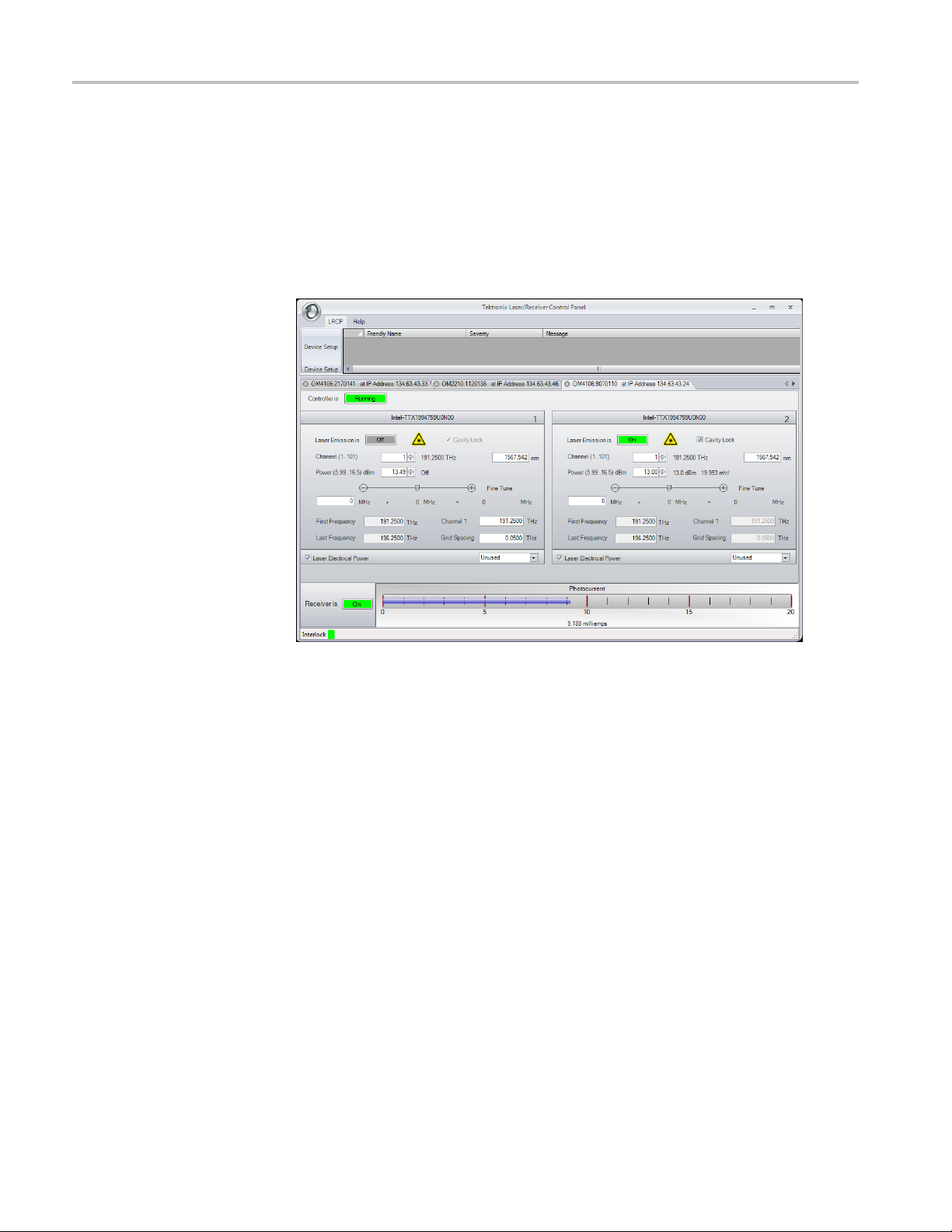
Software over
view
The OM5110 is controlled by the LRCP software. The LRCP automates
locating and configuring all OM devices on the network. It also provides a
Windows Comm
local or remote process to operate the connected devices for ATE (automated
test equipment) applications. The LRCP program can control any number of
OM-series devices including the OM4000 and OM2000 series and the OM5110.
Each device that the LRCP controls is assigned a tab that is labeled with the
device name and IP address. Clicking on the tab brings the control pane for that
device to the front. The contents of the control pane depend on that tabs device.
The following figure shows the pane for the OM5110.
unication Foundation (WCF) service interface to allow another
Figure 6: OM5110 controls (LRCP)
Device setup and auto
configure
18 OM5110 User Manual
Click the LRCP and D evice Setup button to open the Device Setup dialog
box. Use this dialog box on first setup of the controllers and any time network
configuration changes and devices are moved to a new IP address. Click the Auto
Configure button to have LRCP search for and list detected OM devices. Make
sure to exit the form by clicking the OK button to save changes.
An important setting on the Device Setup screen is the Friendly Name. The
Friendly Name field is a way to attach custom labels for each device, to help you
identify the type and/or location of the controllers. Friendly Names are retained in
the LRCP and are tied to the corresponding MAC Address.

Operating basics
Connecting to your OM
instruments
Use the Set IP bu
necessary in a network environment that is not using DHCP to automatically
assign IP Addresses. The Set IP button only changes the IP address and does not
save other modified fields like Friendly Name. How you manage IP addresses in
your network, namely with or without DHCP, determines the method you use to
connect the LRCP and d evices on your network. (See page 8, Set the instrument
IP address.
Once configured and detected, devices are listed as tabs on the main LRCP
screen. They are listed with the friendly name and IP address to allow for easy
identific
laser panels will populate with the laser manufacturer and model number.
Once the
the control p anel attaches to the OM4000 series or OM5110 instrument. First,
the button will turn yellow and read "Connecting…" indicating that a physical
network connection is being established over a socket. Second, the button will
turn teal and read "Connected…". This indicates that a session is established
between the device and Control Panel. Commands are sent to initialize the
commu
turns bright green when the controller and lasers are ready.
ation. Lasers are numbered and once the controller is brought online the
user presses the button that reads Offline the button will change colors as
nications with the laser and identify their capabilities. Finally, the button
tton to manually set the instrument IP address. This is only
)
NOTE. The button color scheme (bright green = running or active, gray = off line
or inactive, red = warning or error state) is consistent throughout the application.
The very first time the LRCP connects to an OM5110, there is a delay while the
LRCP calculates the initial modulator parameters so that they may be stored away
in the LRCP Program Files directory. The modulator parameters, including null
voltages and Vpi voltages for the various modulator sections, are needed to obtain
roper optical bias for the modulator. The LRCP saves the current state of each
p
OM5110 on first connection so that you c an restore the parameters if needed.
More information on setting the modulator parameters using the “Set Params”
button may be found below.
Once the controller tab is active and the panels have populated with information
received from the devices, you can change settings and turn on the laser if
required. When the controller establishes the connection with the OM4000 series
or OM5110 devices, it reads and displays the current state of the device in
the panel. Any time you exit the application, the current state of the device is
preserved by the device, including the emission state. If the device is powered
down, it will return to its default power-on state when it is switched back on.
OM5110 User Manual 19

Operating basics
The Laser controls
If the lasers ar
e used with the OM4000 User Interface (OUI) Software, the laser
usage type must be set using the dialog on the lower right corner of each laser
panel. The OUI uses the setting to determine the laser from which frequency
information is retrieved. A selected usage type (such as Reference) can only be
selected once among all of the OM devices to which you are connected.
NOTE. Only the Reference laser selection is important to OUI operation. The
other selec
tions are to help the user remember how each laser is being used.
The Laser control area of the LRCP software displays available laser control
function
s for the connected OM5110 (with optional internal laser).
Table 6: OM5110 Laser controls (LRCP)
Control Description
Channel Type a number or use the up/down arrows to choose a channel. The
range of channels available will depend on the type of laser, the First
Frequency, and the Grid. The finer the Grid, the more channels are
available for a given laser. The channel range is indicated next to
the word Channel. The laser channel can also be set by entering a
wavelength in the text box to the right of the channel entry. The laser
will tune to the nearest grid frequency.
Cavity Lock The Intel/Emcore ITLA laser that is included in the OM5110 instrument
has the ability to toggle its channel lock function. Ordinarily, Cavity
Lock s hould be checked so that the laser is able to tune, change power
level, and lock on to its frequency reference. However, once tuning is
complete and the laser has stabilized, you can clear this box to turn off
the frequency dither needed for locking the laser to its reference. The
laser can hold its frequency for days without the benefit of the frequency
dither. This feature is helpful where the lowest phase noise is required.
Power
Fine Tune
First F requency
Last Frequency
Channel 1 Settable when emission is off. This is the definition of Channel 1.
Grid Spacing Settable (with 100 MHz resolution) when emission is off. 0.1, 0.05
Sets the laser power level. Type or use the up/down arrows to select the
laser power level. The allowed power range is shown next to the control.
Enables tuning the laser off grid up to 12 GHz. Change this value by
typing a number in the text box or by dragging the slider. The sum of the
text box and slider values is sent to the laser. Once the laser accepts
the new value it is displayed after the ‘=’ sign.
Readout only. The lowest frequency to which you can tune the laser.
Readout only. The highest frequency to which you can tune the laser.
or 0.01THz are typical choices. Use 0.01 THz if tuning to arbitrary
(non-ITU-grid) frequencies. Using this grid plus Fine Tune, any
frequency in the laser band is accessible.
20 OM5110 User Manual

Table 6: OM5110 Laser controls (LRCP) (cont.)
Control Description
Laser Electrical
Power
Emission
Connected To
This should normally be checked. Unchecking this box turns off
electrical power to the laser module. This should only be needed to
reset the laser to its power-on state, or to preserve laser lifetime if a
particular laser is never used.
Click to turn on or off front panel laser emission. The emission status
is indicated both by the green background of the button and by the
corresponding green LED on the OM5110 instrument front panel.
Use the drop-down to select where this laser is connected. The control
software needs to know if this laser is being used as the Reference for
a coherent receiver. Select Reference if this laser is connected to the
Reference (LO) input of a coherent receiver.
Operating basics
The Modulator controls
Auto settings view
(Auto-Set check box
selected)
The Modulator section of the LRCP software is used to control the optical bias
settings of the optical modulator in the OM5110.
The Au
to-Set check box, at the bottom of the control area, enables or disables the
modulator automatic optical bias function s ettings screen. When the check box is
selected, settings are controlled automatically based on the specified signal level
and type. When Auto-Set is cleared, you can manually enter modulator settings.
Table 7: OM5110 Modulator controls (Auto-Set mode) (LRCP)
trol
Con
Input Signal
RF
Level (mVpp)
Signal Type Sets the input signal type.
Apply
Sig. Pwr (Readout only) The Modulated Output Signal power (abbreviated Sig.
Reset
cription
Des
t whether the input signal to each OM5110 input (X-I, X-Q, Y-I, and
Se
Y-Q) is less than or greater than the listed value.
Valid types are No Signal, Binary data signal, and Multi-level data signal.
Send the settings to the OM5110. When the wait circle disappears, your
ettings have been applied. The OM5110 retains these settings until
s
they are changed. No settings are sent or retained by the OM5110 until
you click the Apply button.
Pwr.) readout at the bottom of the Modulator control area. If the output
is too high or too low, it may temporarily affect the controller circuits
of the OM5110. In this case the power readout changes color and
mouse-over text is available to indicate that optical bias and power
readout may not be precise. There is no harm operating like this if the
input optical power is within the specified range.
Sets the optical bias control voltages to the default values. This is
helpful whenever a major change is made to the system such as turning
on the laser or input signals. Clicking Reset generally helps the system
reach steady-state operation the fastest.
OM5110 User Manual 21

Operating basics
Manual settings view
(Auto-Set check box
cleared)
The Manual Sett
ings View provides the greatest degree of control flexibility, but
is more complex than Automatic Settings View. Since each setting may take
five seconds to be stored in the OM5110 and possibly several minutes to reach
steady state, it is best to use the Automatic Settings View where all the settings
are established at once. The Manual Settings View is helpful when it is necessary
to make fine adjustments to optimize a signal, or when it is desirable to impair
the signal.
The following controls are available in the manual modulator view:
Table 8: OM
Control Description
Slope Usually - for > 500 mVpp inputs and + for < 500 mVpp inputs. The -
Control Mode Auto to use automatic optical bias control based on feedback from the
Voltage/Offset
Actual This column shows the voltages at the optical modulator bias inputs.
al Mode
Sign
Set Modulator
Parameters
5110 Modulator controls (manual mode) (LRCP)
causes lock at minimum attenuation and the + at maximum attenuation.
output o
Manual to set the optical modulator bias voltage to a particular value.
The sli
mode or to set the Offset when in Auto mode. Offset is the amount to
offset the bias from where it would normally be in Auto mode. The units
are arb
The O ffset must be tuned while observing the Modulated Optical Output
signal on an appropriate optical signal analyzer to obtain the desired
signa
The v
The o
of electrical signal input. Binary signals require 2-pol QPSK mode.
QAM signals generally require QAM mode. Again it is best to use the
Aut
Mode automatically.
The 6 modulator sections of the OM5110 modulator (X-I, X-Q, Y-I, YQ,
XP, and YP), each have particular null voltages where that section
ou
between null and peak transmission. This information is needed by
the OM5110 optical bias controller to properly control the modulator
se
The null voltages do change with time, and are different for different RF
drive levels. It is not important for these values to be very precise. You
s
achieve proper optical bias within a few minutes. Providing a better set
of null voltages speeds the time to proper optical bias.
T
and may be left at their factory-set values.
ptical signal.
der control is used to set the desired voltage when in Manual
itrary and vary based on Optical Input power.
l behavior.
alue in parentheses is the actual Offset value.
ptical bias controller behaves differently depending on the type
omatic Settings View which chooses the most appropriate S ignal
tputs m inimum optical power, and Vpi voltages, the voltage difference
ctions. The O M 5110 is preprogrammed at the factory.
hould update your modulator parameters only if the OM5110 fails to
he Vpi voltages do not change appreciably with time or temperature
To determine the optimal Null Voltage values:
22 OM5110 User Manual

Operating basics
1. Connect the OM5
the signal quality of the OM5110. Connect the necessary signal inputs and
turn on the laser source.
2. Use the Modulator Auto-Set view to set up the OM5110 for the required
signal types and drive levels. Click Apply. Wait for this step to complete.
3. Deselect the Auto-Set box to see the Manual Settings view. Wait for the
analyzer to report that the optical bias is correct.
4. If the optical bias does not meet your requirements, use the Manual Control
Mode or the Offset function to correct the optical bias.
5. Record the voltages shown on the Manual Settings view once the optical
bias value meets your requirements.
6. Click Set Params. Enter the voltages shown in the Manual Settings view
(step 5) as the Null Voltages in the Set Parameters dialog box.
NOTE. If using Set Params results in worse values, click Restore Initial Values
to reload the settings originally detected by the LRCP at first connection to the
OM511
0.
110 to an analyzer, such as the OM4106D, that will report
The Driver Amp controls
7. Click OK.
8. To verify the Null Voltage values, change every segment to Manual Control
Mode and click Reset. The voltages shown should match those found in
step 5) to within 0.01 V.
9. Return to the Auto-Set view and click Apply to return to automatic control.
e Driver Amp control area of the LRCP software controls the behavior of the
Th
optical modulator RF Input electrical amplifier. This two-stage amplifier can
work in both linear and nonlinear modes to enable both linear electrical-to-optical
conversion and binary optical signal generation which is insensitive to the
electrical input signal level.
OM5110 User Manual 23

Operating basics
Table 9: OM5110
Control Description
Stage 1 First stage of electrical amplification. You can adjust the gain of each
Stage 2 Second stage of electrical amplification. When operating with
Voltage Settings Save current voltages as power-on defaults, which stores all of the
Driver Amp controls (LRCP)
Stage 1 amplifier. This should not be needed for most applications, but
can be helpfu
the linear range (< 500 mVpp electrical input).
>500 mVpp electrical input, you can adjust the crossing point and
amplitude o
not effective in the linear range (< 500 mVpp) and can be left at their
default values.
current Dr
Restore to factory defaults, w hich loads the factory default values for
the Driver Amp, overriding the current values.
When the O
power switch, or when it loses mains power, only the “power-on default
settings,” and “factory defaults” are retained.
l to balance the amplitude of I- Q signals when operating in
f the signal driving the optical modulator. These controls are
iver A mp settings in the OM5110 as the new defaults.
M5110 is turned on and off by the rear-panel Primary
Each of the adjustments for linear gain, nonlinear crossing point, and nonlinear
ude are indicated by a value in percent. This value is provided to help
amplit
documentation of the amplifier settings. The control is not strictly proportional
to this value, so these settings must be determined experimentally using the
appropriate optical signal analyzer.
24 OM5110 User Manual

Appendix A: The automated test equipment (ATE) interface
LRCP has two types of WCF interface to allow control from a user application.
Both types of interface provide full functionality and compatibility with simple
interfaces s
The LRCP ATE interface
uch as MATLAB and client application programs.
Basic/Advanced WCF
service interface for the
LRCP
The Automa
through a Windows Communication Foundation (WCF) service. As the LRCP is
used with all OM4000 series or OM5110 instruments, its interface exposes more
commands than those used by the instrument CLSA.
The WCF services (basic and advanced) are available on port 9000 in the machine
that is running the LRCP. The service (basic and advanced) interface was
developed for incorporation into an ATE client application that you can develop in
your choice of .NET language, typically C# or VB.NET. Both services expose
most of the functionality that is available through the LRCP’s user interface.
The basic service, implemented using a wsBasicHTTPBinding, exposes the
same subset of commands as the advanced service. It was implemented using
asimp
page 37, ATE functionality in MATLAB.) or Labview that only support the
wsBasicHTTPBinding. The basic service is referenced at the following URL:
http://localhost:9000/LaserReceiverControlPanel/Laser_ReceiverServiceBasic/
The advanced service, implemented using a wsHTTPBinding, (and which is not
available in MATLAB) was developed for use with an ATE client application and
uses events to provide a time-efficient interface.
The advanced service is referenced at the following URL:
http://localhost:9000/LaserReceiverControlPanel/Laser_ReceiverService/
ted Test Equipment (ATE) interface exposes the LRCP functionality
ler binding for compatibility with applications like MATLAB (See
NOTE. For safety reasons, you cannot activate a laser from the basic or advanced
ervices; you can only activate a laser from the LRCP user interface.
s
OM5110 User Manual 25

Appendix A: The automated test equipment (ATE) interface
LRCP service interface
function list
The following a
re the available commands in both the basic and advanced service
interfaces and show their functionality using the MATLAB syntax.
int Available
Lasers(classname);
Description: Returns the count of available lasers on the active controller.
Controller T
Example:
ypes: All
AvailableLasers(Obj);
Returns: ans = 2
bool Calibrate();
Descripti
on: Performs an automatic modulator calibration to determine
the optimal modulator parameters. These are the same parameters that
are manually set using the user interface Set Params button, or the
SetManualCalibration() function.
Calibrate() is an automatic calibration that requires the modulator control mode
(see GetActualModulatorMode()) be set to 2-pol QPSK and that >500 mVpp
binary signals are applied to all four inputs. Longer patterns are better (2
PRBS is optimal). Each of the four input patterns should be different in some
way: a
different pattern, the same pattern delayed, or a different seed.
The modulator must receive adequate input power levels to produce a signal
power
that is high enough to avoid a power level warning. If these conditions
are not met the resulting calibration can result in unstable optical bias. See the
section on Set Paramaters to restore these values to initial (factory) values.
Controller Types: OM5110
Example:
Calibrate(Obj);
Returns: ans = true/false
31
bool Connect(classname);
Description: Connects to the active controller, starts controller running.
ntroller Types: All
Co
Example:
Connect(Obj);
Returns: ans = true
bool Disconnect(classname);
Description: Disconnects from the active controller, takes offline.
Controller Types: All
Example:
Disconnect(Obj);
Returns: ans = true
bool GetActualCavityLock(classname);
Description: Returns the actual cavity lock state for the active controller/laser.
Locked = True.
Controller Types: All
Example:
GetActualCavityLock(Obj);
Returns: ans = true
26 OM5110 User Manual

Appendix A: The automated test equipment (ATE) interface
double GetActu
alChannel(classname);
Description: Returns the actual channel number for the active controller/laser.
Controller Types: All
Example:
GetActualChannel(Obj);
Returns: ans = 1
double GetActualChannel1(classname);
Description: Returns the actual channel 1 frequency (in THz) for the active
laser.
Controlle
Example:
rTypes: All
GetActualChannel1(Obj);
Returns: ans = 191.5
controlmode GetActualControlMode(classname, modulatorenum);
Description: Returns the control mode for the modulator that is passed in
the ‘modulator’ parameter.
Controller Types: OM5110
Example:
Return
controlmode.automatic
controlmode.manual
controlmode.notset
GetActualControlMode(obj, modulatorenum.YQ);
s: ans = one of the following:
float GetActualCurrent(classname, string);
Description: Returns current (mA) associated with the specified input voltage.
Controller Types: OM5110
Example:
urns: ans = 30
Ret
GetActualCurrent(obj, “YQ G1”);
The following are valid string values:
"YQ G1", "YI G1", "YQ G2", "YI G2", "YQ D2", "YI D2" "XI D2", "XQ
D2", "XI G2", "XQ G2", "XI G1", "XQ G1"
bool GetActualEmitting(classname);
Description: Returns the emission status of the active laser. Emitting = True.
Controller Types: All
Example:
GetActualEmitting(Obj);
Returns: ans = true
byte GetActualFactoryDefault(classname, string);
Description: Returns the factory default value for the specified voltage, in
the range of 0 to 255.
Controller Types: OM5110
Example:
GetActualFactoryDefault(obj, “XQ D2”);
Returns: ans = 0
The following are valid string values:
"YQ G1", "YI G1", "YQ G2", "YI G2", "YQ D2", "YI D2" "XI D2", "XQ
D2", "XI G2", "XQ G2", "XI G1", "XQ G1"
OM5110 User Manual 27

Appendix A: The automated test equipment (ATE) interface
short GetActua
lFineTuneFrequency(classname);
Description: Returns the actual fine tune frequency (in MHz) of the active
laser.
Controller Types: All
Example:
GetActualFineTuneFrequency(Obj);
Returns: ans = 0
double GetActualGridSpacing(classname);
Description: Returns the actual grid spacing (in THz) of the active laser.
Controlle
Example:
rTypes: All
GetActualGridSpacing(Obj);
Returns: ans = 0.05
byte GetActualMaxPotSetting(classname, string);
Description: Returns the maximum allowed step setting value for the specified
voltage, in the range of 0 to 255
Controller Types: OM5110
Example:
Return
GetActualMaxPotSetting(obj, “XI G1”);
s: ans = 100
The following are valid string values:
"YQ G1", "YI G1", "YQ G2", "YI G2", "YQ D2", "YI D2" "XI D2", "XQ
D2", "XI G2", "XQ G2", "XI G1", "XQ G1"
float GetActualMaxVoltage(classname, string);
Description: Returns the maximum voltage value for the specified voltage,
olts.
in V
Controller Types: OM5110
Example:
GetActualMaxVoltage(obj, “YI D2”);
Returns: ans = 10.2
The following are valid string values:
"YQ G1", "YI G1", "YQ G2", "YI G2", "YQ D2", "YI D2" "XI D2", "XQ
D2", "XI G2", "XQ G2", "XI G1", "XQ G1"
byte GetActualMinPot(classname, string);
Description: Returns the minimum allowed step setting value for the specified
voltage, in the range of 0 to 255
Controller Types: OM5110
Example:
GetActualMinPot(obj, “XI G2”);
Returns: ans = 100
The following are valid string values:
"YQ G1", "YI G1", "YQ G2", "YI G2", "YQ D2", "YI D2" "XI D2", "XQ
D2", "XI G2", "XQ G2", "XI G1", "XQ G1"
28 OM5110 User Manual

Appendix A: The automated test equipment (ATE) interface
float GetActual
MinVoltage(classname, string);
Description: Returns the minimum voltage value for the specified voltage,
in Volts.
Controller Types: OM5110
Example:
GetActualMinVoltage(obj, “YQ G1”);
Returns: ans = 5.5
The following are valid string values:
"YQ G1", "YI G1", "YQ G2", "YI G2", "YQ D2", "YI D2" "XI D2", "XQ
D2", "XI G2", "XQ G2", "XI G1", "XQ G1"
modulatormode GetActualModulatorMode();
Description: Returns the modulator mode (notset, dpqpsk, qam, or arbirary)
Controller Types: OM5110
:
Example
GetActualModulatorMode(obj);
Returns: ans = one of the following:
modulatormode.notset
modulatormode.dpqpsk
modulatormode.qam
modulatormode.arbitrary
double GetActualOffset(modulatorenum);
Description: Returns the offset voltage adjustment value for the modulator
is in Automatic mode.
that
Controller Types: OM5110
Example:
GetActualOffset(obj);
Returns: ans = offset value
double GetActualPower(classname);
Description: Returns the actual power (in dBm) of the active laser.
Controller Types: All
Example:
eturns: ans = 14.5
R
GetActualPower(Obj);
byte GetActualPowerOnDefault(classname, string);
Description: Returns the power-on default setting for the specified voltage, in
the range of 0 to 255.
Controller Types: OM5110
Example:
GetActualPowerOnDefault(obj, “YQ G1”);
Returns: ans = 150
The following are valid string values:
"YQ G1", "YI G1", "YQ G2", "YI G2", "YQ D2", "YI D2" "XI D2", "XQ
D2", "XI G2", "XQ G2", "XI G1", "XQ G1"
slope GetActualSlope(classname, modulatorenum);
Description: Returns the slope setting (positive, negative, or notset) of the
specified modulator (XI, XQ, Y I, YQ).
Controller Types: OM5110
OM5110 User Manual 29

Appendix A: The automated test equipment (ATE) interface
Example: GetAc
tualSlope(obj, modulatorenum.XQ);
Returns: ans = one of the following:
slope.notset
slope.positive
slope.negative
byte GetActualStep(classname, string);
Description: Returns the step setting for the specified voltage, in the range
of0to255.
Controlle
Example:
rTypes: OM5110
GetActualStep(obj, “YQ G1”);
Returns: ans = 10
double GetActualVoltage(classname, modulatorenum);
Description: Returns the voltage setting of the specified modulator (XI, XQ,
YI, YQ), in Volts.
Controller Types: OM5110
Example:
Return
GetActualVoltage(obj, modulatorenum.YQ);
s: ans = setting in Volts
double GetCalculatedFrequency(classname, laserusagetype);
iption: Searches all o f the connected controllers for the first laser of the
Descr
specified laser usage type and returns the calculated frequency (in THz).
Valid usage types are: unused, signalx, signaly, signalxy, reference.
Controller Types: All
Example:
GetCalculatedFrequency(Obj, reference);
Returns: ans = 191.5
string[] GetControllers(classname);
Description: Returns a list (array) of controller devices (strings) that are being
ntrolled by the serving application.
co
Example:
Controllers = GetControllers(Obj);
Returns:
'OM5110:Prototype1'
'OM2210:8180123'
'OM4006:6300121'
double GetFirstFrequency(classname);
Description: Returns the first frequency (in THz) of the active laser.
Controller Types: All
Example:
GetFirstFrequency(Obj);
Returns: ans = 191.5
30 OM5110 User Manual

Appendix A: The automated test equipment (ATE) interface
bool GetInterl
ock(classname);
Description: Returns the current interlock state of the active controller. The
normal, working state is TRUE. If the interlock is disconnected from the back
of the instrument or if the instrument is powered off, this function returns
FALSE.
Controller Types: All
Example:
tInterlock(Obj);
Ge
Returns: ans = true
string Get
IP(classname);
Description: Returns the IP Address (as a string) for the active controller.
Controller Types: All
Example:
Address = GetIP(Obj);
Returns: Address = ‘172.17.200.114’
double GetLastFrequency(classname);
Description: Returns the last frequency (in THz) of the active laser.
Controller Types: All
e:
Exampl
GetLastFrequency(Obj);
Returns: ans = 196.25
e GetOpticalPower(classname);
doubl
Description: Returns the optical power setting, in dBm.
Controller Types: OM5110
Example:
GetOpticalPower(obj);
Returns: ans = 12.4
double GetOpticalPowerAdjustment(classname);
Description: Returns the optical power adjustment setting, in dBm.
Controller Types: OM5110
Ex
ample:
GetOpticalPowerAdjustment(obj);
Returns: ans = 10.4
oat GetPhotoCurrent(classname);
fl
Description: Returns the photocurrent (in mA) of the receiver in the active
controller.
Controller Types: 4006, 4106
Example:
GetPhotoCurrent(Obj);
Returns: ans = 11.034
string GetPolarization(classname);
Description: Returns the polarization state.
Valid Polarization states: filter1, filter2, unknown, hardwarefailed.
Controller Types: 2210
Example:
GetPolarization(Obj);
Returns: ans = filter2
OM5110 User Manual 31

Appendix A: The automated test equipment (ATE) interface
bool Initializ
ePolarization(classname);
Description: Sets the initial polarization state. Returning True = Successful.
Controller Types: 2210
Example:
InitializePolarization(Obj);
Returns: ans = true
bool IsActiveControllerChosen5110Y(classname);
Description: Returns true if the active controller is an OM5110; returns false
if it is not an OM5110.
Controlle
Example:
rTypes: OM5110
IsActiveControllerChosen5110Y(obj);
Returns: ans = true/false
The ATE methods for the modulator use the following enumerations:
modulat
orenum (YQ, YI, YP, XQ, XI, XP)
modulatormode (noset, dpqpsk, qam, arbitrary)
slope (notset, negative, positive)
controlmode (notset, automatic, manual)
bool Reset(classname);
Description: Resets the modulator.
Controller Types: OM5110
Example:
Retu
Reset(obj);
rns: ans = true/false
bool SetActiveControllerByIPAddress(classname, string_ipAddress);
cription: Sets the active c ontroller by IP Address. True = Successful.
Des
Controller Types: All
Example:
‘172.17.200.112’);
SetActiveControllerByIPAddress(Obj,
Returns: ans = true
Returns (after GetIP(Obj)): ans = ‘172.17.200.112’
bool SetActiveControllerByName(classname, string_activeController);
Description: Sets the active controller by name. True = Successful.
Controller Types: All
Example:
SetActiveControllerByName(Obj, 'OM4106:6300121');
Returns: ans = true
bool SetActiveLaser(classname, byte_activeLaser);
Description: Sets the active laser. Returning True = Successful.
Controller Types: All
Example:
SetActiveLaser(Obj, 2);
Returns: ans = true
32 OM5110 User Manual

Appendix A: The automated test equipment (ATE) interface
bool SetDesire
dCavityLock(classname, bool_desiredCavityLock);
Description: Sets the desired cavity lock state for the active l aser. 1 (True) =
Locked. Returning True = Successful.
Controller Types: All
Example:
SetDesiredCavityLock(Obj, 1);
Returns: ans = true
bool SetDesiredChannel(classname, int_desiredChannel);
Description: Sets the channel number for the active laser. Returning True =
Successfu
l.
Controller Types: All
Example:
SetDesiredChannel(Obj, 45);
Returns: ans = true
bool SetDesiredChannel1(classname, double_desiredChannel1);
Description: Sets the channel 1 frequency (in THz) for the active laser. Can
only be set if the active laser is NOT emitting. Returning True = Successful.
Controller Types: All
e:
Exampl
SetDesiredChannel1(Obj, 192.5);
Returns: ans = true
etDesiredControlMode(classname, m odulatorenum, controlmode);
bool S
Description: Sets the control mode of the specified modulator. Returns true if
control mode was set, or false if mode was not set.
Controller Types: OM5110
Example:
controlmode.automatic);
urns: ans = true/false
Ret
SetDesiredControlMode(obj, modulatorenum.XI,
bool SetDesiredEmittingOff(classname);
scription: Sets the Active Laser to Off (not emitting). Returning True =
De
Successful.
Controller Types: All
Example:
SetDesiredEmittingOff(Obj);
Returns: ans = true
bool SetDesiredEmittingOn(classname);
Description: Sets the Active Laser to emitting. Returning True = Successful.
Controller Types: All
Example:
SetDesiredEmittingOn(Obj);
Returns: ans = true
bool SetDesiredFineTuneFrequency(classname,
short_desiredFineTuneFrequency);
Description: Sets the desired fine tune frequency (in MHz) of the active laser.
Controller Types: All
Example:
SetDesiredFineTuneFrequency(Obj, 300);
Returns: ans = true
OM5110 User Manual 33

Appendix A: The automated test equipment (ATE) interface
void SetDesire
dFrequency(double desiredFrequency);
Description: Sets the channel and fine tune frequency of the selected laser to
the specified frequency.
Controller Types: 2210, 2012
bool SetDesiredGridSpacing(classname, double_desiredGridSpacing);
Description: Sets the desired grid spacing (in THz) of the active laser. Can
only be set if the active laser is NOT emitting. Returning true = Successful.
Controller Types: All
Example:
etDesiredGridSpacing(Obj, 0.05,0);
S
Returns: ans = true
bool SetD
esiredModulatorMode(classname, modulatormode);
Description: Sets the specified modulator mode. Returns true if mode was set,
or false if m ode was not set.
Controller Types: OM5110
Example:
SetDesiredModulatorMode (obj, modulatormode.qam)
Returns: ans = true/false
bool SetDesiredOffset(classname, modulatorenum, double);
Description: Sets the offset for the specified modulator. Returnstrueifoffset
was se
t, or false if offset was not set.
Valid offset value range depends on the modulator that is being set:
Qand
I modulators range from -2000 to 2000.
P modulators range from -6000 to 6000.
Controller Types: OM5110
Example:
SetDesiredOffset(obj, modulatorenum.XI, 2000);
Returns: ans = true/false
bool SetDesiredPower(classname, double_desiredPower,
bool_waitUntilFinished);
Description: Sets the desired power (in dBm) of the active laser. For
aitUntilFinished, 0 (False) = don’t wait. Returning True = Successful.
W
Controller Types: All
Example:
SetDesiredPower(Obj, 13, 0);
Returns: ans = true
bool SetDesiredPowerOnDefault(classname, string, byte);
Description: Sets the default power-on value for the specified voltage. Returns
true if value was set, or false if value was not set.
Controller Types: OM5110
Example:
SetDesiredPowerOnDefault(obj, “YI G1”, 125);
Returns: ans = true/false
The following are valid string values:
"YQ G1", "YI G1", "YQ G2", “YI G2", "YQ D2", "YI D2" "XI D2", "XQ
D2", "XI G2", "XQ G2", "XI G1", "XQ G1"
34 OM5110 User Manual

Appendix A: The automated test equipment (ATE) interface
bool SetDesire
dSlope(classname, modulatorenum, slope);
Description: Sets the slope for the specified modulator to positive or negative.
Returns true if slope was set, or false if slope was not s et.
Controller Types: OM5110
Example:
slope.positive);
Returns: an
SetDesiredSlope(obj, modulatorenum.XI,
s = true/false
bool SetDesiredVoltage(classname, modulatorenum, double);
Descripti
on: Sets the voltage of the specified modulator. Returns true if
voltage was set, or false if voltage was not set.
Controller Types: OM5110
Example:
SetDesiredVoltage(obj, modulatorenum.XI, 10.2);
Returns: ans = true/false
bool SetDesireStep(classname, string, byte);
Description: Sets the step for the specified voltage. Returns true if value
was set, or false if value was not set.
Contro
Example:
ller Types: OM5110
SetDesireStep(obj, “YQ G1”, 135);
Returns: ans = true/false
The following are valid string values:
"YQ G
1", "YI G1", "YQ G2", “YI G2", "YQ D2", "YI D2" "XI D2", "XQ
D2", "XI G2", "XQ G2", "XI G1", "XQ G1"
l SetManualCalibration();
boo
Description: This is the same as the SetParams button in the user interface.
It sends a new set of null voltages and Vpi voltages to the OM5110 for use
by the optical bias controller. Returns true if the calibration was successfully
started, and false if the calibration was not started.
Controller Types: OM5110
xample: Calibrate(obj, float, float, float, float, float, float, float, float, float,
E
float, float, float);
Returns: ans = true/false
bool SetOpticalPowerAdjustment(classname, double);
Description: Sets the optical power adjustment, in dBm. Returns true if power
adjustment value was set, false if the value was not set.
Controller Types: OM5110
Example:
SetOpticalPowerAdjustment(obj, 10.1);
Returns: ans = true/false
bool SetPolarizationIn(classname);
Description: Puts both polarization filters in. Returning True = Successful.
Controller Types: 2210
Example:
SetPolarizationIn(Obj);
Returns: ans = true
OM5110 User Manual 35

Appendix A: The automated test equipment (ATE) interface
bool SetPolari
zationOut(classname);
Description: Puts both polarization filters out. Returning True = Successful.
Controller Types: 2210
Example:
SetPolarizationOut(Obj);
Returns: ans = true
bool SetReceiverOff(classname);
Description: Turns the receiver off in the active controller. Returning True =
Successful.
CAUTION. M
ake sure that laser power is off before running this command,
otherwise the photoreceiver could be damaged.
NOTE. To
turn off lasers, click the LRCP software Laser Emission button to Off,
or push the front-panel Power button to power off the instrument.
Contro
Example:
ller Types: 4006, 4106
SetReceiverOff(Obj);
Returns: ans = true
bool SetReceiverOn(classname);
Description: Turns the receiver on in the active controller. Returning True =
Successful.
Controller Types: 4006, 4106
Example:
urns: ans = true
Ret
SetReceiverOn(Obj);
void TogglePolarization(classname);
scription: Toggles the polarization state by moving both filters to the
De
opposite position.
Controller Types: 2210
Example:
TogglePolarization(Obj);
36 OM5110 User Manual

Appendix A: The automated test equipment (ATE) interface
ATE functiona
LRCP control
lity in MATLAB
MATLAB supports a limited subset of services, namely the Basic service. This
section describes how to create and address the functions from MATLAB.
The Laser/Receiver Control Panel communicates with other programs using port
9000 on the computer running the Control Panel software. MATLAB 2009a has a
built-in capability that makes control from MATLAB easy if you are running the
February 2
NOTE. Make sure that the LRCP is running before using this interface.
ize the interface in the MATLAB desktop command window with the
Initial
following commands:
url = 'ht
Laser_ReceiverServiceBasic/?wsdl';
create
obj = Laser_ReceiverServiceBasic;
Where:
010 or later release of the L aser/Receiver Control Panel.
tp://localhost:9000/LaserReceiverControlPanel/
ClassFromWsdl(Url);
The first specifies the URL or path to a WSDL application programming interface
(API) that defines the web service methods, arguments, and transactions for the
LRCP.
The second creates the new class based upon that API and builds a series of
M-Files for accessing the Laser/Receiver Control Panel service.
The third instantiates the object class name and opens a connection to the service.
These commands only need to be run anytime the service interface (available
methods) changes.
To get an up-to-date listing of methods for the service, type the following:
methods(obj)
Matlab should return the same functions and any new functions that have been
added. These functions are self-documented when they are generated. By
enablingtheMATLABhelpwindow,youcanfind out the function’s parameters
by typing the function name followed by a “(“ and waiting for the help to display.
OM5110 User Manual 37

Appendix A: The automated test equipment (ATE) interface
38 OM5110 User Manual

Appendix B: Cleaning and maintenance
Cleaning
Use a dry, soft cotton cloth to clean the external OM5110 case. Do not use
any liquid cleaning agents or chemicals that could possibly infiltrate the
enclosure,
If the dust filter on the underside of the unit becomes clogged, use a small
vacuum or b
From time to time it is necessary to clean the optical input and output
connecto
cleaning swabs made for this purpose to clean each connector.
or that could damage markings or labels.
rush to clean the filter.
rs on the front of the unit. Use square-ended optical connector
Maintenance
Do not at
not necessary.
There are no user-serviceable components or subsystems within the OM5110.
Attempting any internal repairs will void your warranty. Never remove the
external lid on the unit.
If it becomes necessary to replace the fuse in the power input module in the
rear of the unit, use a 5X20mm “slo-blo” fuse rated at 3.15 A, 250 V
small screwdriver to gently pry open the fuse drawer.
WAR N ING. Disconnect the unit from the power source when changing the fuse to
ure that line voltage is not present during the replacement.
be s
tempt to clean inside the instrument; cleaning of internal parts is
.Usea
AC
OM5110 User Manual 39

Appendix B: Cleaning and maintenance
40 OM5110 User Manual

Index
A
AC line voltage requirements, 4
Accessories
optional, 2
standard, 2
ATE interface, 25
Auto settings view, 2 1
AvailableLasers, 26
B
Basic and
advanced interface
commands list, 26
C
Calibrate, 26
Cleaning and maintenance, 39
Connect, 26
Connecting to your OM
uments, 19
instr
Controls and connectors
front panel, 13
rear panel, 14
D
Description
product overview, 1
vice setup and auto
De
configure, 18
Disconnect, 26
E
Environmental operating
requirements, 4
Equipment setup
real-time (RT)
oscilloscopes, 17
F
Features, 1
First product inspection, 3
Front panel labels, viii
G
General safety summary, iv
GetActualCavityLock, 26
GetActualChannel, 26
GetActualChannel1, 27
GetActualControlMode, 27
GetActual
GetActualEmitting, 27
GetActualFactoryDefault, 27
GetActualFineTuneFrequency, 28
GetActualGridSpacing, 28
GetActualMaxPotSetting, 28
GetActu
GetActualMinPot, 28
GetActualMinVoltage, 28
GetActualModulatorMode, 29
GetActualOffset, 29
GetActualPower, 29
GetA
GetActualSlope, 29
GetActualStep, 30
GetActualVoltage, 30
GetCalculatedFrequency, 30
GetControllers, 30
tFirstFrequency, 30
Ge
GetInterlock, 31
GetIP, 31
GetLastFrequency, 31
GetOpticalPower, 31
GetOpticalPowerAdjustment, 31
GetPhotoCurrent, 31
GetPolarization, 31
Current, 27
alMaxVoltage, 28
ctualPowerOnDefault, 29
I
Important safety information, iv
Incoming inspection, 3
InitializePolarization, 32
IsActiveControllerChosen5110Y, 32
K
Key features, 1
L
Laser safety labels, viii, ix
LRCP ATE interface, 25
LRCP control (from
MATLAB), 37
LRCP interface commands
AvailableLasers, 26
Calibrate, 26
Connect, 26
Disconnect, 26
GetActua
GetActualChannel, 26
GetActualChannel1, 27
GetActualControlMode, 27
GetActualCurrent, 27
GetActualEmitting, 27
GetAc
GetActualFineTuneFrequency, 28
GetActualGridSpacing, 28
GetActualMaxPotSetting, 28
GetActualMaxVoltage, 28
GetActualMinPot, 28
Get
GetActualModulatorMode, 29
GetActualOffset, 29
GetActualPower, 29
GetActualPowerOnDefault, 29
GetActualSlope, 29
etActualStep, 30
G
GetActualVoltage, 30
GetCalculatedFrequency, 30
GetControllers, 30
GetFirstFrequency, 30
GetInterlock, 31
GetIP, 31
GetLastFrequency, 31
GetOpticalPower, 31
GetOpticalPowerAdjustment, 31
GetPhotoCurrent, 31
GetPolarization, 31
InitializePolarization, 32
IsActiveControllerChosen5110Y, 32
Reset, 32
SetActiveControllerByIPAddress, 32
lCavityLock, 26
tualFactoryDefault, 27
ActualMinVoltage, 28
OM5110 User Manual 41

Index
SetActiveCont
SetActiveLaser, 32
SetDesiredCavityLock, 33
SetDesiredChannel, 33
SetDesiredChannel1, 33
SetDesiredControlMode, 33
SetDesired
SetDesiredEmittingOn, 33
SetDesiredFineTuneFrequency, 33
SetDesiredFrequency, 34
SetDesiredGridSpacing, 34
SetDesiredModulatorMode, 34
SetDesir
SetDesiredPower, 34
SetDesiredPowerOnDefault, 34
SetDesiredSlope, 35
SetDesiredVoltage, 35
SetDesireStep, 35
nualCalibration, 35
SetMa
SetOpticalPowerAdjustment, 35
SetPolarizationIn, 35
SetPolarizationOut, 36
SetReceiverOff, 36
SetReceiverOn, 36
glePolarization, 36
Tog
LRCP service interface function
list, 26
rollerByName, 32
EmittingOff, 33
edOffset, 34
M
Manual description, xv
Manual settings view, 22
O
Operating requirements, 4
Optional accessories, 2
Options
C (one C-band laser), 2
instrument, 2
international power cords, 3
L (one L-band laser), 2
NL (no laser), 2
P
PC require
Power cord option, 3
Power requirements, 4
Product description, 1
ments, 5
R
Rear panel labels, ix
Requirements
AC line
environmental, 4
operating, 4
PC, 5
Power, 4
Reset, 32
voltage, 4
S
vice safety summary, vi
Ser
Set instrument IP address
DHCP-enabled network, 8
non-DHCP network, 9
overview, 8
SetActiveControllerByIPAddress, 32
etActiveControllerByName, 32
S
SetActiveLaser, 32
SetDesiredCavityLock, 33
SetDesiredChannel, 33
SetDesiredChannel1, 33
SetDesiredControlMode, 33
SetDesiredEmittingOff, 33
SetDesiredEmi
SetDesiredFineTuneFrequency, 33
SetDesiredFrequency, 34
SetDesiredGridSpacing, 34
SetDesiredModulatorMode, 34
SetDesiredOffset, 34
SetDesired
SetDesiredPowerOnDefault, 34
SetDesiredSlope, 35
SetDesiredVoltage, 35
SetDesireStep, 35
SetManualCalibration, 35
SetOptic
SetPolarizationIn, 35
SetPolarizationOut, 36
SetReceiverOff, 36
SetReceiverOn, 36
Software installation
contr
overview, 6
Standard accessories, 2
Symbolsandtermsonthe
product, vii
ttingOn, 33
Power, 34
alPowerAdjustment, 35
oller PC, 7
T
Terms in this manual, vii
e Driver Amp controls, 23
Th
The Laser controls, 20
The Modulator controls, 21
TogglePolarization, 36
W
WCF interface, 25
Windows Communication
Foundation (WCF)
service, 25
42 OM5110 User Manual
 Loading...