

Page 1

OM2210
xx
ZZZ
Coherent Receiver Calibration Source
User Guide
*P071305001*
071-3050-01
Page 2

Page 3

xx
OM2210
ZZZ
Coherent Receiver Calibration Source
User Guide
www.tektronix.com
071-3050-01
Page 4

Copyright © Tektronix. All rights reserved. Licensed software products are owned by Tektronix or its subsidiaries
or suppliers, and are protected by national copyright laws and international treaty provisions.
Tektronix products are covered by U.S. and foreign patents, issued and pending. Information in this publication
supersedes that in all previously published material. Specifications and price change privileges reserved.
TEKTRONIX and TEK are registered trademarks of Tektronix, Inc.
Contacting Tektronix
Tektronix, Inc.
14150 SW Karl Braun Drive
P.O. Box 5 0 0
Beaverto
USA
For product information, sales, service, and technical support:
n, OR 97077
In North America, call 1-800-833-9200.
Worl dwid e, v isit www.tektronix.com to find contacts in your area.
Page 5

Warranty
Tektronix warrants that this product will be free from defects in materials and workmanship for a period of one (1)
year from the date of shipment. If any such product proves defective during this warranty period, Tektronix, at its
option, either will repair the defective product without charge for parts and labor, or will provide a replacement
in exchange for the defective product. Parts, modules and replacement products used by Tektronix for warranty
work may be n
the property of Tektronix.
ew or reconditioned to like new performance. All replaced parts, modules and products become
In order to o
the warranty period and make suitable arrangements for the performance of service. Customer shall be responsible
for packaging and shipping the defective product to the service center designated by Tektronix, with shipping
charges prepaid. Tektronix shall pay for the return of the product to Customer if the shipment is to a location within
the country in which the Tektronix service center is located. Customer shall be responsible for paying all shipping
charges, duties, taxes, and any other charges for products returned to any other locations.
This warranty shall not apply to any defect, failure or damage caused by improper use or improper or inadequate
maintenance and care. Tektronix shall not be obligated to furnish service under this warranty a) to repair damage
result
b) to repair damage resulting from improper use or connection to incompatible equipment; c) to repair any damage
or malfunction caused by the use of non-Tektronix supplies; or d) to service a product that has been modified or
integrated with other products when the effect of such modification or integration increases the time or difficulty
of servicing the product.
THIS WARRANTY IS GIVEN BY TEKTRONIX WITH RESPECT TO THE PRODUCT IN LIEU OF ANY
OTHER WARRANTIES, EXPRESS OR IMPLIED. TEKTRONIX AND ITS VENDORS DISCLAIM ANY
IMPLIED WARRANTIES OF MERCHANTABILITY OR FITNESS FOR A PARTICULAR PURPOSE.
TRONIX' RESPONSIBILITY TO REPAIR OR REPLACE DEFECTIVE PRODUCTS IS THE SOLE
TEK
AND EXCLUSIVE REMEDY PROVIDED TO THE CUSTOMER FOR BREACH OF THIS WARRANTY.
TEKTRONIX AND ITS VENDORS WILL NOT BE LIABLE FOR ANY INDIRECT, SPECIAL, INCIDENTAL,
OR CONSEQUENTIAL DAMAGES IRRESPECTIVE OF WHETHER TEKTRONIX OR THE VENDOR HAS
ADVANCE NOTICE OF THE POSSIBILITY OF SUCH DAMAGES.
[W2 – 15AUG04]
btain service under this warranty, Customer must notify Tektronix of the defect before the expiration of
ing from attempts by personnel other than Tektronix representatives to install, repair or service the product;
Page 6

Page 7

Table of Contents
1 SAFETY INFORMATION ...................................................................................................................... 5
1.1 SAFETY NOTICES ............................................................................................................................. 5
1.2 LASER SAFETY ................................................................................................................................. 5
1.3 OM2210 LASER LABELS AND LOCATIONS .......................................................................................... 6
2 INTRODUCTION ................................................................................................................................... 7
2.1 PURPOSE ......................................................................................................................................... 7
2.2 THE OPTAMETRA CALIBRATION APPROACH ....................................................................................... 7
3 GETTING STARTED ........................................................................................................................... 10
3.1 CONFIGURING THE HARDWARE ....................................................................................................... 10
4 OPTAMETRA CALIBRATION SOFTWARE ........................................................................................ 18
4.1 INSTALLATION ................................................................................................................................ 18
4.2 OPERATION .................................................................................................................................... 18
4.3 RESULTS ....................................................................................................................................... 25
5 MAINTENANCE AND CLEANING ...................................................................................................... 26
5.1 MAINTENANCE................................................................................................................................ 26
5.2 CLEANING ...................................................................................................................................... 26
6 APPENDIX A – REFERENCE DOCUMENTS .................................................................................... 27
6.1 SOFTWARE LICENSE AGREEMENT .................................................................................................... 27
Optametra OM2210 Calibration Source User Guide V1.0.1 1/7 ©2011 Page 4 of 29
Page 8

CAUTION
CAUTION
!
WARNING
!
CAUTION
!
!
1 Safety Information
1.1 Safety Notices
Indicates a potentially hazardous condition or procedure that could result in damage to the
instrument.
Indicates a potentially hazardous condition or procedure that could result in minor or moderate bodily
injury.
Indicates a potentially hazardous condition or procedure that could result in serious injury or death.
This symbol on the unit indicates that the user should consult this document for further
information regarding the nature of the potential hazard and actions that should be taken to
avoid or mitigate the hazard.
1.2 Laser Safety
The laser sources included in this product are classified according to IEC/EN 60825-1:
1994+A1:2001+A2:2001 and IEC/EN 60825-2:2004
This laser product complies with 21CFR1040.10 except for deviations pursuant to Laser Notice No.
50, dated June 24, 2007.
Use of controls or adjustments or performance of procedures other than those specified
herein may result in hazardous radiation exposure.
Under no circumstances should you use any optical instruments to view the laser output
directly.
Optametra OM2210 Calibration Source User Guide V1.0.1 1/7 ©2011 Page 5 of 29
Page 9
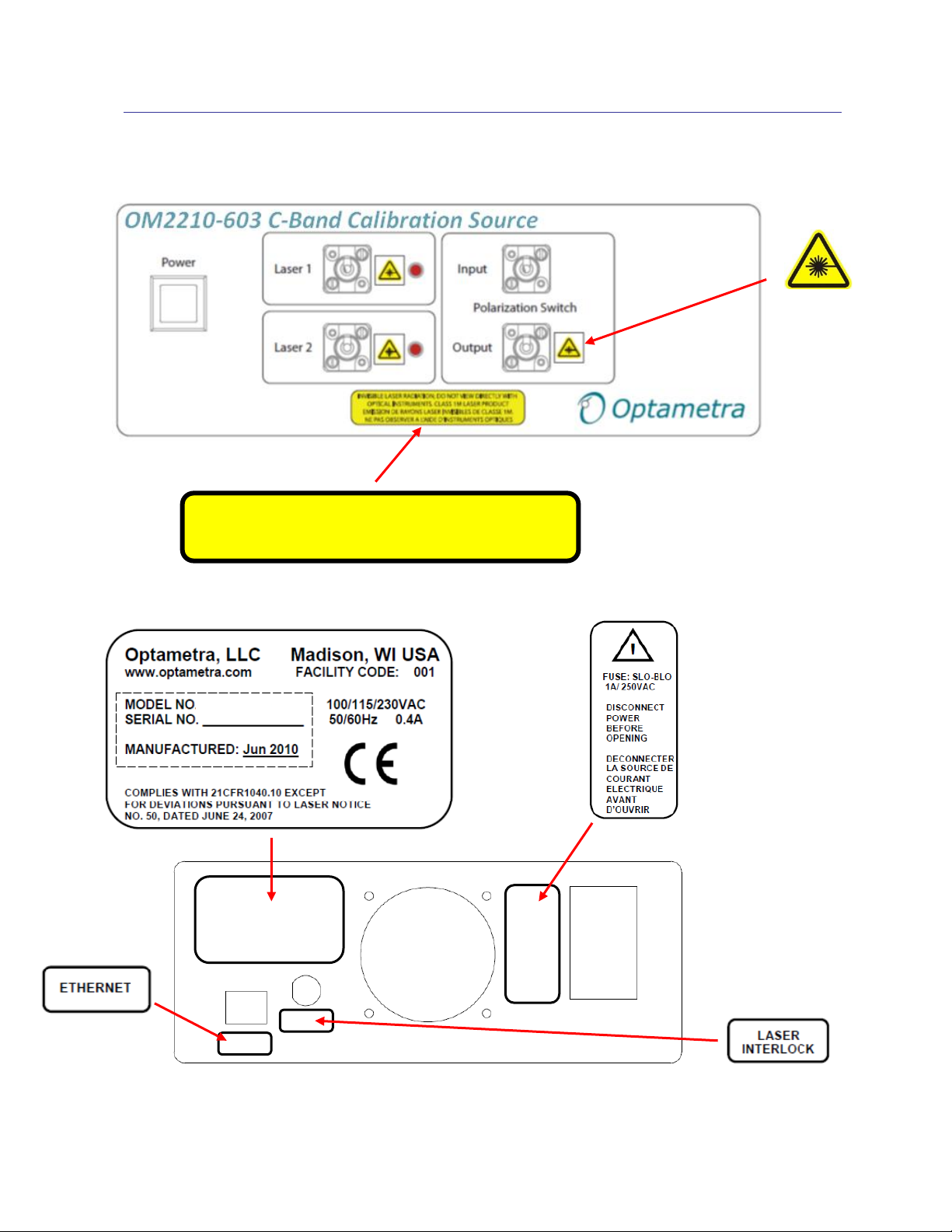
Indicates the
INVISIBLE LASER RADIATION; DO NOT VIEW DIRECTLY WITH
EMISSION DE RAYONS LASER INVISIBLES DE CLASSE 1M.
OM2210
1.3 OM2210 Laser Labels and Locations
location of a
laser aperture
OPTICAL INSTRUMENTS. CLASS 1M LASER PRODUCT
Optametra OM2210 Calibration Source User Guide V1.0.1 1/7 ©2011 Page 6 of 29
Page 10

EV H
2 Introduction
2.1 Purpose
The Optametra calibration products, featuring the OM2210 Calibration Source and Optametra‟s
proprietary software, are used in laboratory or industrial facilities to calibrate coherent fiber optic
receivers. These products are primarily targeted for calibrating polarization-diverse, phase-diverse
receivers that are linear or can be set in a linear mode. The end result is a transfer matrix,
measured at a particular heterodyne frequency over a specified wavelength range, which describes
the optical-to-electrical transfer function of the analog portion of the receiver. The transfer matrix is
then used to compute critical receiver specifications such as quadrature phase angle, polarization
cross-talk, and path gains. This information can be used for quantitative evaluation of the receiver,
or to provide calibrated optical field measurements when used with the Optametra signal analysis
software.
2.2 The Optametra Calibration Approach
Optical communications signals can be described as the combination of a continuous (cw) laser field
and a modulation field which carries the data. In the case of polarization multiplexed signals, there
can be as many as two independent lasers and modulators that are polarization multiplexed
together. Optametra signal processing software is designed to extract the cw and modulation for
each polarization from which data and signal quality metrics may be extracted. Since the software
extracts fields, not just data, it is necessary to have independent measurements of the receiver
properties so that the effect of the receiver may be removed. This process consists of a lowfrequency measurement of the linear OE transfer matrix relating the input field vector, E, to the
output voltages, V, and a separate frequency response measurement. The Optametra calibration kit
is provided to measure the linear OE transfer matrix, H, at frequencies well within the oscilloscope
bandwidth.
This process can be applied both to linear receivers like the Optametra OM3105 as well as
receivers with automatic gain control (AGC ) such as commercial coherent receivers. The AGC
must be turned off during the calibration so that the software can measure the linear portion of the
transfer function. The matrix can then be normalized to simulate the AGC operation.
Optametra OM2210 Calibration Source User Guide V1.0.1 1/7 ©2011 Page 7 of 29
Page 11

The Optametra calibration kit contains the OM2210 Calibration Source that is available in the various
configurations shown below.
-603 C-band Calibration Source and Software. Includes 2
lasers. Use this option when C-band receiver has no Optametra
sources. (L-band version is -604)
-601 C-band Calibration Source and Software. Includes 1
laser. Use this option when C-band receiver has an Optametra
Reference Laser. (L-band version is -602)
A C+L version is also available (-605)
-600 Calibration Source and Software. Includes no lasers. Use
this option when receiver has 2 Optametra sources for
Reference and Signal.
Figure 1: C or L-band
Calibration Source options
The calibration kit extracts the hybrid matrix, H, by applying a heterodyne signal with different
polarizations and then measuring the resulting sine wave outputs on the oscilloscope and separately
monitoring the power. Proprietary calculations are performed to extract the hybrid matrix in the
presence of receiver impairments, heterodyne phase fluctuations, and channel skews. This process
is directed by the Optametra Hybrid Receiver Calibration (HRC) Software. The HRC software
controls the heterodyne source via the Optametra Laser Receiver Control Panel (LRCP) and collects
data from the oscilloscope via the Optametra User Interface (OUI).
Optametra OM2210 Calibration Source User Guide V1.0.1 1/7 ©2011 Page 8 of 29
Page 12
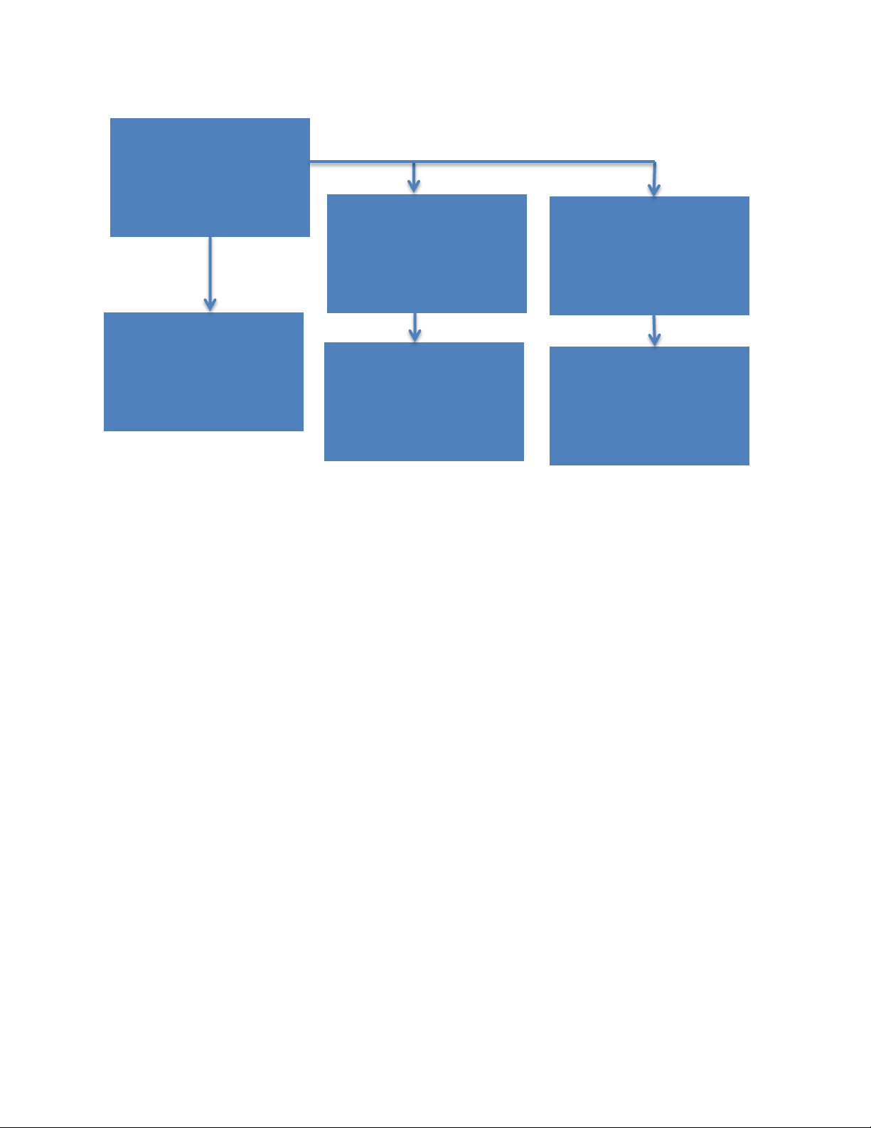
HRC Software
LRCP Software
OUI Software
Power Meter
Oscilloscope
Heterodyne source
and polarization
switch
Figure 2: Hierarchy of the software and hardware used to perform
the calibration
The final results are provided in .mat, .csv, and .xls formats. The .mat format is used by the
Optametra OUI software hybrid calibration function. The other formats are provided for viewing the
results. The results and configurations are also stored in an SQL database.
Optametra OM2210 Calibration Source User Guide V1.0.1 1/7 ©2011 Page 9 of 29
Page 13

3 Getting Started
3.1 Configuring the Hardware
3.1.1 OM2210 Calibration Source
Ensure that the required power sources for the OM2210 (100, 115 or 230 VAC, 50–60 Hz, 0.4A), the
equipment to be calibrated, associated oscilloscope, and the external computer (if used) are
available. Use the IEC power cord provided to connect to a rack or wall outlet.
Associated cabling includes the IEC power cord, an Ethernet cable, and fiber optic cables to connect
the OM2210 and the Device Under Test (DUT).
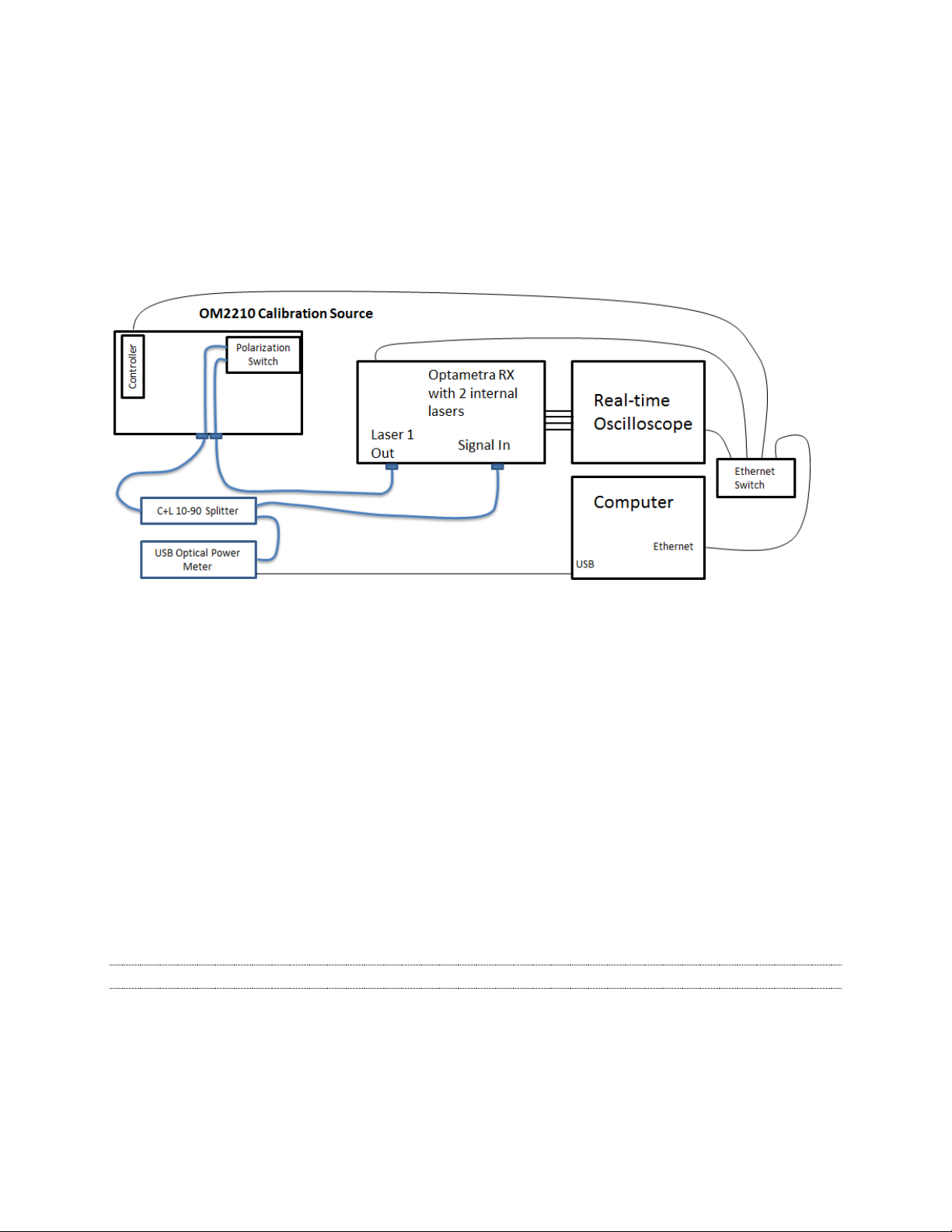
Several options for use of the OM2210 are available. For use with the Optametra OM3105 Coherent
Modulation Receiver, a polarization-maintaining (PM) fiber optic patchcord is used to connect the
OM3105‟s Laser 1 to the OM2210‟s Polarization Switcher Input, and the Polarization Switcher
Output is connected via single-mode (SM) fiber optic patchcord to an optical splitter. From the
splitter, 90% of the optical power is directed to the OM3105 Signal Input, and 10% is routed to an
optical power meter connected to the computer being used to run the calibration. Four coaxial cables
connect the receiver to a high-speed sampling oscilloscope. Ethernet cables connect the OM2210,
via a router, to a computer, receiver and oscilloscope. The Optametra User Interface running on the
computer controls the oscilloscope, while the Laser-Receiver Control Panel (LRCP) controls the
OM3005/3105 and the OM2210.
The OM2210 can also be purchased with internal lasers for use in calibrating receivers that do not
already contain two Optametra tunable lasers that can reach the same wavelength.
Note: A password is required to turn on the lasers through the Laser / Receiver Control Panel.
The default is „1234‟
Optametra OM2210 Calibration Source User Guide V1.0.1 1/7 ©2011 Page 10 of 29
Page 14

1 4 2
5
3
10
7
6
8
9
3.1.2 OM2210 Controls and I/O Connections
Front Panel Controls and I/O Connectors
1. On/Off switch
2. Laser 1 Output (with LED indicator)
3. Laser 2 Output (with LED indicator)
4. Input
5. Output
Rear Panel Controls and I/O Connectors
6. Power switch
7. BNC connector for optional laser remote interlock
8. Ethernet port
9. Fuse drawer
10. Input power receptacle
Optametra OM2210 Calibration Source User Guide V1.0.1 1/7 ©2011 Page 11 of 29
Page 15

WARNING
!
3.1.3 List of Components
OM2210 Calibration Source
IEC power cable
Ethernet cable
BNC shorting cap for interlock
Dust covers for optical inputs not in use (2 or 4)
Additional items supplied by Optametra or another source:
Digitizer or real time oscilloscope with at least 20 GS/s sampling rate on four channels. Agilent, Tek-
tronix, and LeCroy real time oscilloscopes with at least 10GHz bandwidth are supported. The Tektronix 8GHz oscilloscope is also supported.
Power cable
Ethernet cable
Mouse and keyboard (unless touch-screen controlled)
System controller PC running Windows XP, Matlab (if using the OM4x06) and the Optametra User
Interface (OUI) software
o Monitor plus cable
o Mouse and keyboard
o Power cables
o Ethernet cable
An Ethernet switch or hub plus a router running DHCP, and associated cabling (not shown)
SM patch cable ( 1 or 2, depending on the application) to connect the Polarization Switcher Output
to the DUT
PM patch cable to connect the DUT to the Polarization Switcher Input
Optical power meter
Optical amplifier
Optical splitter
To avoid the possibility of electrical shock, do not connect your OM2210 to a power source if
there are any signs of damage to the instrument enclosure.
3.1.4 Electrical Power Requirements
The OM2210 can operate from any AC power source that provides 100, 115, or 230 VAC, at a
frequency of 50 Hz or 60 Hz. The OM2210 must be connected directly to a grounded power outlet
only.
Optametra OM2210 Calibration Source User Guide V1.0.1 1/7 ©2011 Page 12 of 29
Page 16

WARNING
!
CAUTION
CAUTION
!
The OM2210 must be connected to a 100, 115,or 230VAC/50 or 60Hz grounded outlet only.
Operating the OM2210 without connection to a grounded power source could result in
serious electrical shock. Always connect the unit directly to a grounded power outlet.
Protective features of the OM2210 may be impaired if the unit is used in a manner not
specified by Optametra.
3.1.5 Location and Positioning
Be sure to position the OM2210 so that the power switch at the rear of the unit can be easily
accessed.
Be sure not to obstruct the fan so that there is an adequate flow of cooling air to the
electronics compartment whenever the unit is operating.
3.1.6 Operating Environment
The OM2210 may be operated within the following conditions:
Temperature 10°C to +35°C (50°F to +95°F)
Humidity <85%R.H. non-condensing from 10°C to +35°C (50°F to +95°F)
Altitude < 2,000m (6560ft)
Optametra OM2210 Calibration Source User Guide V1.0.1 1/7 ©2011 Page 13 of 29
Page 17

3.1.7 Computer
Operating System: XP Service Pack 3 (.NET 4.0 required), or Windows-7
Processor: min: Intel Pentium 4 or equivalent, recommended: Intel Core2Duo,
Core2Quad, I7, or equivalent; min clock speed 2GHz.
RAM: 3 GB. Future 64-bit releases will benefit from as much memory as is
available.
Hard Drive Space: min 20 GB, 300GB recommended for large data sets
Video Card: NVIDIA dedicated graphics board w/ 512+ MB min. graphics memory;
Consult factory for compatibility if using a different card.
Networking: Gigabit Ethernet (1Gb/s)
Display: Large flat screen recommended for displaying multiple graph types eg. 20”
min
Other Requirements: DVD Optical drive, 2 USB 2.0 ports
Optametra OM2210 Calibration Source User Guide V1.0.1 1/7 ©2011 Page 14 of 29
Page 18
3.1.8 First Setup
Once everything is securely placed, make electrical connections in the following order:
1. Ethernet connections and other computer connections. See 3.1.2
2. Power connections for the OM2210 and other equipment.
3. RF connections from the DUT to oscilloscope
4. Fiber optic patch cable connections from the OM2210 to the DUT.
5. Store all dust covers and coaxial connector caps for future use.
Figure 3: Typical system configuration for calibration of Optametra Receiver. For 3rd
party receiver calibration, use an OM2210 with internal sources to provide the Laser 1
and LO laser functions.
Once the equipment is positioned and connected, turn on the computer, the oscilloscope, the DUT,
and the main power switch on the back of the OM2210. The OM2210 front-panel power button will
light briefly after main power is applied indicating it is searching for a DHCP server. When an IP
address has been assigned or when the search fails in the case of an isolated network, the power
light will go off. Press the power button one time to enable the unit. The steady power button light
indicates the OM2210 is ready for use and that lasers may be activated at any time if a user
connects via the Ethernet connection. The light will go out and the unit will be disabled any time
main power is removed or the IP address is changed. Press the power button to re-enable. This
feature prevents a remote user from activating the lasers when the local user may not be ready.
Note: Ethernet only allows devices on the same subnet to communicate.
You should now have four devices on an Ethernet network: computer, oscilloscope, DUT, and
OM2210. This little network may be connected to your corporate network or router or you may
choose to leave it isolated. IP setup is normally done by Optametra personnel at the time of
installation. You should only need the following instructions if you are reconfiguring your network.
Optametra OM2210 Calibration Source User Guide V1.0.1 1/7 ©2011 Page 15 of 29
Page 19

3.1.8.1 IP setup on a network with DHCP (dynamic IP assignment)
DHCP allows “automatic” assignment of the IP address the connected devices need to communicate
with each other. However, automatic IP assignment must be selected on each device before this will
be allowed. The OM2210 is shipped with automatic IP assignment enabled. Your computer and
oscilloscope may need this turned on.
Once automatic IP assignment is selected, you may still need the cooperation of your corporate IT
department to get IP addresses assigned. If you are using a centralized server, ask your network
administrator to make an IP reservation for you so that you get the same number each time the
device is powered on. Once these are set up for the oscilloscope and the OM2210 you will have no
trouble finding them in the future.
Once your equipment gets an IP address from DHCP you can find that address using the operating
system of the oscilloscope or computer. For example, in the XP operating system there is a window
that looks like the one below. Notice that when you select the active Ethernet connection the IP
address shows up in the Details box in the lower-left corner of the window.
To configure the IP connection of the OM2210, please see the OM4006/OM4106 User Guide
Chapter on using the Laser Receiver Control Panel (LRCP).
3.1.8.2 IP setup on an isolated network or one not running a DHCP server
When there is no DHCP server, the Ethernet connected devices don‟t know what address to assign
to themselves. In this case you must manually set the IP address. On a corporate network this
means getting the IP addresses from your network administrator first and then setting each device.
Optametra OM2210 Calibration Source User Guide V1.0.1 1/7 ©2011 Page 16 of 29
Page 20

Your network administrator may need the MAC addresses of the computer, oscilloscope, and
OM2210. Contact Optametra if you need the MAC address for your OM2210. On newer models the
MAC address is printed on the real-panel label. Please see the OM4006/OM4106 User Guide
Chapter on using the Laser Receiver Control Panel (LRCP) to set the IP address. If you have a
network isolated from your corporate network you are free to use any IP numbering scheme.
Optametra recommends 172.17.200.XXX where XXX is any unique number between 0 and 255
(each device needs a unique number). There is nothing special about this scheme other than that it
is the default for new OM2210 units. Use the operating systems of the oscilloscope and computer to
set their IP addresses. The first three sets of numbers in the IP address need to be the same on the
computer and the connected devices for them to communicate in most cases.
Optametra OM2210 Calibration Source User Guide V1.0.1 1/7 ©2011 Page 17 of 29
Page 21

Feature
Number
Description
3
Optametra User Interface (OUI)
4
Optametra Signal Analysis Software
14
QAM and advanced formats
15
Hybrid Calibration
4 Optametra Calibration Software
4.1 Installation
The Optametra software is primarily distributed through the website http://portal.optametra.com . Call
Optametra if you need login credentials. Each customer location has a web page where the
customer can download the latest release as well as installation instructions and User‟s Guides.
Follow the installation instructions provided with the release you are installing. In general, Optametra
software consists of two portions: the Optametra software and the drivers needed for the software to
work with hardware components.
An important part of the Optametra software is the copy protection provided by the USB HASP key.
The HASP key is used in two ways: 1) It prevents the software from being run in more places than
there are HASP keys, and 2) it enables or disables features such as QAM and hybrid calibration. To
see which features are available on your key, you can direct a web browser to http://localhost:1947
and click on HASP Keys and Features. The following features are presently available:
4.2 Operation
As shown in Figure 2, the Optametra Hybrid Receiver Calibration (HRC) program controls the
Optametra User Interface (OUI) and the Laser Receiver Control Panel (LRCP). The OUI in turn
controls the oscilloscope, while the LRCP controls the Optametra hardware. To launch the complete
application, use the following procedure.
1) First follow the instructions in the Measurement Setup section to get the hardware configured
properly and powered up.
2) Launch the OUI. Click the “Show Matlab” button on the Setup tab. Delete the contents of the
Matlab Engine Window or place a % before each line since it will not be used for computations.
a. Click on Connect and use the dialog box to select four channels.
b. Be sure to enable four channels
Optametra OM2210 Calibration Source User Guide V1.0.1 1/7 ©2011 Page 18 of 29
Page 22

c. Disconnect
For further information on the OUI, see the OM4006/OM4106 Users Guide.
3) Launch the LRCP. Connect to the Optametra hardware that will be used for the calibration.
Turn on the lasers that will be used for the calibration and tune them to the same wavelength.
For further information on the LRCP, see the OM4006/OM4106 Users Guide.
4) Launch the HRC
5) Connect the USB Power Meter to the computer that is running the HRC. Be sure both lights on
the Power Meter are on.
6) Configure the system using the HRC. Click on System Configuration
7) Click on the Configure Equipment button and choose Configure Laser Source
Optametra OM2210 Calibration Source User Guide V1.0.1 1/7 ©2011 Page 19 of 29
Page 23

a. Be sure the that LRCP window shows a connection to the Calibration Source and all of
the laser sources to be used in the calibration
b. Click on Refresh to pull the information from the LRCP into the HRC, then click Close
8) Now choose Configure Oscilloscope
9) The Configure Oscilloscope screen helps you define the oscilloscope connection. Typical values
are shown above. The trailing command, ::INSTR is required for most instruments. Each oscilloscope setup has a Friendly Name that can be used for recalling the settings.
10) Follow the setup instructions shown to get a good heterodyne signal on the oscilloscope.
11) After making adjustments on the oscilloscope front panel, always press the “Single” button on
the oscilloscope front panel to get it ready for external control
12) Close the window when complete. Now choose File Locations.
a. The default location for the CoreProcessing Directory is
C:\Program Files (x86)\Optametra\OUI4006\. Don’t change this unless the OUI installed
to a different directory. For example, on 32 bit machines the directory is
C:\Program Files\Optametra\OUI4006\.
Optametra OM2210 Calibration Source User Guide V1.0.1 1/7 ©2011 Page 20 of 29
Page 24

b. Browse to where you would like to save the results files by clicking on the Folder Icon on
the Results Folder row. It is best to choose … My Documents\Optametra\HybridReceiver Calibration\ to easily find the files again.
13) Next choose Configure Power Meter. Enter the correct serial number to replace the default val-
ue. The connect string, USB0::0x1313::0x8072::P2000608::INSTR has the serial number as the
last digits. The Power Meter serial number is printed on the body of the Power Meter. Choose a
Power Multiplier of 10 if the 10% coupler is being used to monitor the power.
14) Now it is time to setup the calibration. Click on the Calibration Setup tab and set the following
in the main body of the HRC on the left side:
a. Click New in the upper left of the Calibration Setup tab to create a new setup unless you
want to modify an existing setup.
b. Name: this is the base name that will be used with the time and date to form the file-
name for the results. It will also be used to recall this setup in the future. Use the serial
number of the device under test for easiest recall of data.
c. Choose the Reference Laser (LO), Signal Laser (the one connected through the polariza-
tion switch), and Polarization Switch using the drop-down menus.
d. Laser Line Width in Hz. This sets the time constant for the phase recovery algorithm.
Only an estimate is required. 100,000 is the best choice for Optametra ECDLs.
e. Start Channel, End Channel, Channel Step define the wavelength channels over which
the calibration will be performed. The channel definition is set by the LRCP. The calibration will be taken a number of times set by the Repeat Count and then averaged for
each wavelength.
f. The Record Length should be set so that the time window width on the oscilloscope is at
least 0.2 / (Line Width) or more. For a 100,000 Hz Line Width, a good choice is a 4us
window which is 200,000 samples at 20ps/sample.
g. Choose the oscilloscope configuration from the drop-down menu
h. Set the frequency limit for the heterodyne frequency during the calibration. Typical val-
ues of 400 to 900 MHz work well with ~40-50Gs/s oscilloscopes. The frequency can be
lower for lower sampling rates. The upper frequency should be <1/3 the system bandwidth to minimize phase error.
Click Save to store your settings for future use.
15) Click on Channel Delays. Enter the relative skew between channels 1 to 2, 1 to 3, and 1 to 4 in
the boxes provided if known. To determine the relative channel delays, this utility can measure
phase vs. frequency over a given range and find the average slope. Enter the min and max frequencies for the utility to use. These should auto-populate to equal to the range shown on the
Optametra OM2210 Calibration Source User Guide V1.0.1 1/7 ©2011 Page 21 of 29
Page 25

Calibration Setup window, but you can measure delays over any frequency range less than
10GHz. The range chosen should also be less than ~1/3 the oscilloscope bandwidth setting.
Once the range is set, click Recalculate Delays.
Once the utility completes a sweep over the desired range at a wavelength in the center of the
band to be tested, it will fill in the Channel Delays. Inspect the Matlab plot to verify that the data was taken over the desired range and is well behaved. You may also type Status in the separate Matlab program window to see the rms and peak phase error in the measurement. Close
the Recalculate Channel Delays utility to use these values.
16) (for advanced users) As mentioned above, entering a Frequency Range and Clicking on Recalcu-
late Delays will sweep the heterodyne frequency while measuring the resulting channel to
channel phase relationship. The slope of the phase vs. frequency gives the average channel delays. Alternatively, the FindChannelDelays function can be run from the OUI Matlab Engine
Window. Running the function manually in this way gives you more control over which frequencies are used for the delay calculation. When complete, you can type Status in the Matlab
Command Window to see the results and error magnitude.
17) Now that the system is configured, click on Calibration, then Start Calibration to get the calibra-
tion started.
18) The following screen gives you an opportunity to review the calibration setup before getting the
measurements underway. Once the measurement is started, it may take approximately 1 hour
to finish depending on the number of repeats and wavelengths chosen.
Optametra OM2210 Calibration Source User Guide V1.0.1 1/7 ©2011 Page 22 of 29
Page 26

As the HRC executes, it shows the results of each step on a dashboard called “Calibration
Results” on the right side of the window. The area shows the channel and step status as well as
the following:
Calibration Matrix: The actual values being output to the calibration data file
Polarization Extinction: A list of calculated crosstalk levels based on the measured calibration
matrix.
Gain: the Relative gain between channels
Power A, B: Power measured for each polarization setting
Freq A, B: Measured heterodyne frequency at each polarization setting
Phase Data: Quadrature phase angles and calculated I-Q crosstalk
Optametra OM2210 Calibration Source User Guide V1.0.1 1/7 ©2011 Page 23 of 29
Page 27

Optametra OM2210 Calibration Source User Guide V1.0.1 1/7 ©2011 Page 24 of 29
Page 28

187 188 189 190 191 192 193 194 195 196
-5
0
5
Laser Frequency (THz)
Measured Quadrature Phase Error
Phase12-90
Phase34-90
187 188 189 190 191 192 193 194 195 196
-5
0
5
Laser Frequency (THz)
Measured Relative Gain (dB)
Gain 1-2
Gain 3-4
Gain 1-3
Gain 1-4
4.3 Results
The output of the calibration is both a hybrid-matrix data set and a set of calculated performance
metrics. These plots are updated at each wavelength step. Channels 1,2,3,4 are X-I, X-Q, Y-I, Y-Q
respectively. Example data is shown below:
These plots are calculated from the pHybTable variable which is the primary output of the program.
The pHybTable has one row for each laser channel tested: a column for each of the 8 entries in the
complex pHyb matrix and a first column for the laser channel frequency. This information is stored in
the following ways:
1) The pHybCalib.mat file. This file is designed for use with the OUI4006. To do so, move the file
from the place designated in the File Locations path to Program Files
(x86)\Optametra\ExecFiles. Rename the old version in case you need to go back. If the file
name is changed in any way, the OUI will not use the file. When using the OUI, you may type
load pHybCalib in the separate Matlab program window and then type SerialInformation to see
which file is in use.
2) The data is also stored in .mat, .csv, and .xls files in the directory indicated in the File Locations
box.
3) The configuration information is stored in an SQL database called OPTAMETRA in the
OPTAMETRACONFIG SQL server. SQL Server Management Studio Express (SSMSE) from Microsoft is a free program that can be used to examine the database.
Optametra OM2210 Calibration Source User Guide V1.0.1 1/7 ©2011 Page 25 of 29
Page 29

WARNING
!
CAUTION
!
5 Maintenance and Cleaning
5.1 Maintenance
There are no user-serviceable components or subsystems within the OM2210. Attempting any
internal repairs will void your warranty. Never remove the external lid on the unit.
Removing the dust covers from the laser output connectors while the lasers are operating
may result in exposure to invisible laser radiation. Never view directly with optical
instruments.
If it becomes necessary to replace the fuse in the power input module in the rear of the unit, use
a 5X20mm “slo-blo” fuse rated at 1A, 250VAC. Use a small screwdriver to gently pry open the
fuse drawer.
Disconnect the unit from the power source when changing the fuse to ensure that line
voltage is not present during the replacement.
5.2 Cleaning
To clean the outside of the OM2210 enclosure, use a dry, soft cotton cloth. Do not use any liquid
cleaning agents or chemicals that could possibly infiltrate the enclosure, or that could damage
markings or labels.
If the dust filter on the underside of the unit becomes clogged, use a small vacuum or brush to
clean the filter.
From time to time it will be necessary to clean the optical input and output connectors on the
front of the unit. Use square-ended swabs made for this purpose to clean each connector.
Do not attempt to clean the inside of the instrument; cleaning of internal parts is not necessary.
Optametra OM2210 Calibration Source User Guide V1.0.1 1/7 ©2011 Page 26 of 29
Page 30

6 Appendix A – Reference Documents
6.1 Software license agreement
This Software License Agreement ("AGREEMENT") is entered into between OPTAMETRA, LLC
("OPTAMETRA") and the licensee purchasing Core Processing software ("LICENSEE"). In
consideration of the mutual obligations described in this AGREEMENT and other good and valuable
consideration, the sufficiency and receipt of which are hereby severally acknowledged, the parties
agree as follows: 1. Term. This AGREEMENT shall become effective upon acceptance by
OPTAMETRA and shall continue in effect until terminated in accord with Section 10.
2. License.OPTAMETRA grants to LICENSEE a nonexclusive, perpetual, nontransferable
license to use its proprietary software known as Core Processing ("SOFTWARE").
3. Scope of Use. LICENSEE may use SOFTWARE only to process its own data. Any parent,
subsidiary, or affiliate of LICENSEE shall require a separate license to use SOFTWARE. LICENSEE
may copy SOFTWARE for itself so long as LICENSEE reproduces all copyright notices and other
proprietary legends on such copy. LICENSEE may run multiple copies of software on several
computers at the same time. LICENSEE shall not reverse assemble, reverse compile, or unlock
SOFTWARE in whole or in part for any reason. LICENSEE will not remove, obscure or alter any
proprietary rights notice or trademark and/or service mark rights notice which OPTAMETRA places
on or in SOFTWARE. LICENSEE shall not rent SOFTWARE or give SOFTWARE to third parties or
provide third parties with access to SOFTWARE through a commercial timesharing arrangement or
based on any other method for any reason.
4. Title. Title to SOFTWARE, including but not limited to, originals, translations, compilations
and partial copies, if any, shall not pass to LICENSEE.
5. Nondisclosure. LICENSEE understands and agrees that SOFTWARE contains confidential
and proprietary information and data ("CONFIDENTIAL INFORMATION"). During and subsequent to
the term of this AGREEMENT, LICENSEE shall protect such CONFIDENTIAL INFORMATION to the
same degree that it protects CONFIDENTIAL INFORMATION pertaining to its own business and
shall not disclose CONFIDENTIAL INFORMATION to any third party. LICENSEE shall not, either
directly or through any third party, use any confidential information of OPTAMETRA to create, modify
or enhance any computer software, program or user documentation that is substantially similar to
SOFTWARE and transmit such computer software, program or user documentation to a third party.
Notwithstanding the foregoing, CONFIDENTIAL INFORMATION shall not include information which:
(1) is at the time of disclosure, or thereafter becomes, a part of the public domain through no act or
omission of LICENSEE nor of any employee or agent of LICENSEE; or (2) was in LICENSEE‟s
Optametra OM2210 Calibration Source User Guide V1.0.1 1/7 ©2011 Page 27 of 29
Page 31

possession as shown by written records prior to the disclosure and had not been obtained by
LICENSEE either directly or indirectly from OPTAMETRA; or (3) is hereafter lawfully disclosed to
LICENSEE by a third party who did not acquire the information directly or indirectly from
OPTAMETRA.
The foregoing rights and obligations shall apply reciprocally with regard to information transmitted by
LICENSEE in order to obtain SUPPORT for SOFTWARE and which is designated as confidential by
LICENSEE.
6. Warranty.OPTAMETRA warrants that it is the owner or licensor of SOFTWARE and
OPTAMETRA warrants that it has the authority to license SOFTWARE as set forth in this
AGREEMENT. OPTAMETRA further warrants that SOFTWARE shall at the time of delivery of
SOFTWARE and for a period of ninety (90) days thereafter operate substantially in accordance with
OPTAMETRA' then-current published specifications. In the event that SOFTWARE does not so
operate, OPTAMETRA shall use its best efforts to cure such problem within a reasonable period of
time or to replace LICENSEE's copy of SOFTWARE with another copy of SOFTWARE in
OPTAMETRA' sole discretion. This shall be LICENSEE's sole and exclusive remedy. This warranty
shall not apply if: (1) SOFTWARE was not used in accordance with OPTAMETRA' then-current
published specifications; (2) SOFTWARE was altered, modified or converted by LICENSEE; (3)
LICENSEE's computer(s) malfunctioned and the malfunction caused the defect; (4) LICENSEE has
not paid all invoiced amounts due to OPTAMETRA pursuant to this AGREEMENT; and (5) any other
cause within the control of LICENSEE caused the defect. SOFTWARE shall be deemed working
according to specifications if it works on exemplary data files supplied by OPTAMETRA.
7. Limitation of Liability. THE FOREGOING WARRANTY IS EXCLUSIVE AND IN LIEU OF
ALL OTHER WARRANTIES, EXPRESS OR IMPLIED INCLUDING, BUT NOT LIMITED TO, ANY
IMPLIED WARRANTY OF MERCHANTABILITY OR FITNESS FOR A PARTICULAR PURPOSE.
OPTAMETRA' LIABILITY FOR ANY AND ALL CLAIMS, SHALL NOT EXCEED IN THE
AGGREGATE, THE AMOUNT PAID BY CLIENT TO OPTAMETRA FOR THIS LICENSE. IN NO
EVENT SHALL OPTAMETRA BE LIABLE FOR INDIRECT, SPECIAL OR CONSEQUENTIAL
DAMAGES EVEN IF ADVISED THAT SUCH DAMAGES ARE POSSIBLE.
8. Support and Enhancements. Commencing upon execution of this AGREEMENT, and
thereafter for ninety (90) day terms ("RENEWAL TERMS") LICENSEE shall automatically be entitled
to SUPPORT and ENHANCEMENTS (all described below) for SOFTWARE.
A. Support. "SUPPORT" shall mean that OPTAMETRA shall provide to LICENSEE reasonable
technical email consultation relating to the operation of SOFTWARE.
B. Enhancements. "ENHANCEMENTS" shall mean that OPTAMETRA shall inform LICENSEE
when each new release of SOFTWARE containing system enhancements is made commercially
available, and upon written request from LICENSEE shall provide to LICENSEE one (1) copy of
each such release of SOFTWARE and corresponding technical documentation.
Optametra OM2210 Calibration Source User Guide V1.0.1 1/7 ©2011 Page 28 of 29
Page 32

ENHANCEMENTS shall not mean that OPTAMETRA must provide any improvements to
SOFTWARE announced by OPTAMETRA as separately priced, optional or extra cost
improvements. ENHANCEMENTS shall be covered by the terms of this SOFTWARE LICENSE
AGREEMENT.
9. General.
A. Governing Law. This AGREEMENT will be governed by and interpreted in accordance with
the laws of the State of Wisconsin, excluding its conflict of law principles. In case of a dispute
arising from the interpretation or enforcement of OPTAMETRA‟ or its licensors‟ patents,
trademarks, copyrights, confidential information or other proprietary rights, U.S. federal copyright
law shall apply.
B. Assignment. Any assignment of this AGREEMENT by either party (except to an entity
controlling, controlled by or under common control with said party) without the written consent of
the other shall be void.
C. Severability. Any provision of this AGREEMENT that is held to be invalid by a court of
competent jurisdiction shall be severed from this AGREEMENT, and the remaining provisions
shall remain in full force and effect.
D. Waiver. Failure or delay by either party to enforce compliance with any term or condition of
this AGREEMENT shall not constitute a waiver of such term or condition.
E. Entire Agreement. This AGREEMENT constitutes the entire agreement between the parties
with regard to the subject matter of this AGREEMENT and supersedes all previous
communications, whether oral or written, between the Parties with respect to such subject
matter.
F. Foreign Trade Restrictions. LICENSEE shall not either directly or indirectly export or re-
export SOFTWARE in violation of the Export Administration Regulations promulgated by the
U.S. Department of Commerce.
10. Termination. LICENSEE may terminate this AGREEMENT at any time prior to the shipment
of SOFTWARE from OPTAMETRA. OPTAMETRA may terminate this AGREEMENT upon thirty (30)
days' prior written notice if LICENSEE fails to comply with any of the terms and conditions of this
AGREEMENT or the terms and conditions of the Purchase Order, and such noncompliance is not
cured during said thirty (30) day period. Promptly upon termination of this Agreement, LICENSEE
must immediately return to OPTAMETRA all SOFTWARE and CONFIDENTIAL INFORMATION
delivered by OPTAMETRA to LICENSEE including all copies, if any. LICENSEE's insolvency,
receivership, bankruptcy, or assignment for the benefit of creditors (or the institution of proceedings
therefor) shall immediately terminate this AGREEMENT without notice. Rights and obligations
accruing prior to termination of AGREEMENT shall survive termination of AGREEMENT.
Optametra OM2210 Calibration Source User Guide V1.0.1 1/7 ©2011 Page 29 of 29
 Loading...