

Page 1
Features & Benefits
OI1125 E/O Transmitter
Generates SONET/SDH
Compliant Optical
Waveforms up to 12.5 Gb/s
Internal DFO Laser
at 1550.9 nm
Adjustable Extinction Ratio
from 5 dB to >12 dB
(>12 dB nominal) to Test
with Worst-case Conditions
Accepts a Wide Range of
Input Voltage Levels from
0.25 to 1.5 V
p-p
Remote Operation
and Monitoring
OI2125 O/E Receiver
High Performance Receiver
Supports Data Rates up to
12.5 Gb/s
User-installable Modules
for Clock Recovery at
10.664 Gb/s, 9.953 Gb/s,
2.666 Gb/s, 2.488 Gb/s,
622 Mb/s and 155 Mb/s
Data Rates with a Single
O/E Receiver
Broad Wavelength from
1100 to 1620 nm
High Sensitivity (–16 dBm) to
Detect Low-level Optical
Input Signals
Amplified Electrical Output
to Connect Directly to Most
Commercial Error Analyzers
Applications
Bit Error Rate Testing
Optical Receiver and
Transmitter Testing
Optical Component and
Fiber Loop Testing
Optical Signal Analysis
Remote Operation
for System Integration
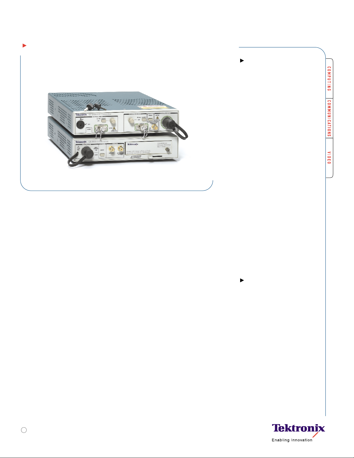
Optical Transmitter and Receiver
OI1125 • OI2125
A High-performance Optical Interface for Bit Error
Rate Testing of Optical Systems, Subsystems and
Components up to 12.5 Gb/s
The Tektronix high-performance OI1125 E/O
transmitter and OI2125 O/E receiver offer a
simple and cost-effective solution for generating and receiving SONET/SDH compliant optical signals for bit error rate (BER) testing and
optical signal analysis up to 12.5 Gb/s. Both
include a remote port for easy integration and
remote monitoring and control in a test system environment. Users can completely control instrument settings, monitor instrument
status and access additional features through
the remote port.
Transmitter Generates
SONET/SDH Compliant Optical
Waveforms up to 12.5 Gb/s for
Testing Optical Subsystems
and Components
Using the internal 1550 nm DFB laser or an
external C-band tunable laser, the OI1125 is
excellent for generating optical signals modulated by a high-performance pattern generator
and is designed so most commercial generators connect directly to the modulation input.
The input voltage range (250 mV to 1.5 V)
accommodates most commercial pattern generators for bit error ratio (BER) testing of optical components and receiver testing.The
adjustable extinction ratio allows testing the
receiver sensitivity at worst-case conditions
without complex test setups.The OI1125 also
generates optical signals for optical signal
analysis of components, systems and subsystems using a CSA8000 sampling oscilloscope.
Receiver Clock Recovery
and Multi-data Rate Support
Simplify Testing of
High-performance Optical
Transmitters, Laser Diodes,
Optical Components and
Fiber Loops
The OI2125 O/E Receiver receives modulated
optical signals up to 12.5 Gb/s from
transmission systems, including SONET/SDH
compatible systems, and converts them to
electrical signals for further testing by equipment such as a bit error rate tester (BERT).
The OI2125 electrical output can be connected
Optical Transmission Test • www.tektronix.com/optical
1
Page 2
Optical Transmitter and Receiver
OI1125 •OI2125
directly to most commercial error analyzers,
and does not require an external amplifier.
The data and clock output voltage ranges
(0.5 to 1.5 V
p-p
) make the OI2125 an excellent
optical interface for most commercial
error analyzers.
With the optional OM1420 and OM1200
modules, the receiver can extract the clock
on signals up to 10.664 Gb/s (OC-192 FEC).
The recovered clock signal can then be used
to trigger a CSA8000 sampling oscilloscope
or serve as the clock input to an error analyzer. Used with the Tektronix TDS/CSA8000
series sampling oscilloscope and a pattern
generator, the OI1125 can create modulated
optical signals for high-speed optical
communications testing, extinction ratio
measurements, eye-pattern analysis and
optical signal analysis.The optical signal is
passed through the DUT and received by
the appropriate 80Cxx sampling head on
the oscilloscope.
A single receiver with the OM1420 and
OM1200 modules supports a broad range
of signal bit rates.The OM1420 OC-192
Dual-rate Clock Recovery Module supports
standard OC-192 (9.953 Gb/s) and
OC-192 FEC (10.664 Gb/s). The OM1200
OC-48 Multi-rate Clock Recovery Module
supports OC-48 (2.488 Gb/s), OC-48 FEC
(2.666 Gb/s), OC-12 (622 Mb/s) and
OC-3 (155 Mb/s) rates.
Optical Transmission Test • www.tektronix.com/optical
2
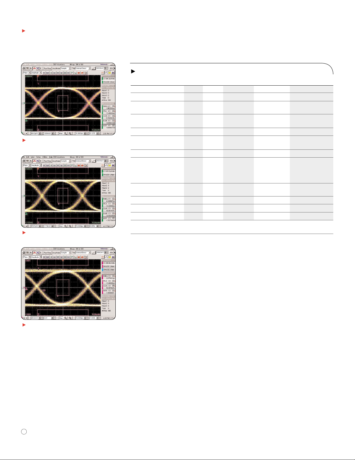
OI1125 eye diagram at 9.953 Gb/s with
OC-192 mask.
OI1125 eye diagram at 12.5 Gb/s with scaled
OC-192 mask.
OI2125 eye diagram at 9.953 Gb/s with
an OC-192 mask.
OI1125 E/O Transmitter Specifications
Specification Min Typ Max Units Comments
Data Rate*
1
2.4 12.5 Gb/s
Data Input Voltage 0.25 1.5 V
p-p
Int. (DFB) Wavelength 1550.82 1550.92 1551.02 nm ±1 nm adjustment
range
Ext. (Modulator) 1530 1565 nm
Wavelength Range*
2
Input Power +5 +12 dBm
Extinction Ratio 12 dB Up to OC-192
10 dB Rates >OC-192
Adjustable Extinction Ratio*3<5 >12 dB (typical)
Peak-to-peak Jitter 0.15 UI Up to OC-192
15 18 ps Rates >OC-192
Data Input Voltage
0.5 to 1.5 V
p-p
Random Jitter 0.02 UI 2 ps
RMS
up to OC-192 Rates >OC-192
Output Power +0 +2 +4 dBm Using the internal laser
Insertion Loss 8 dB
Percent Crossing 45 55 %
Eye Mask Testing*
4
GR-1377-CORE
GR-253-CORE
*1Data rates down to 622 Mb/s are achievable,but specifications are not guaranteed at rates below 2.4 Gb/s.
*
2
Wavelength range from 1565 nm to 1600 nm is achievable, but specifications are not guaranteed above 1565 nm.
*
3
The range of adjustment for the extinction ratio may vary from unit to unit, but is typically 5dB to >12 dB.The OI1125 is calibrated
with the adjustable extinction ratio disabled. Specifications are guaranteeed at the calibrated (fixed) position.
*
4
No mask hits with 5% mask margin for OC-48, OC-192, and 12.5 Gb/s (scaled OC-192 mask).
Page 3

Optical Transmitter and Receiver
OI1125 •OI2125
Characteristics
Environment
Temper ature–
Operating: 0°C to +40°C.
Nonoperating: –40°C to +71°C.
Humidity –
Operating: 5% to 95% RH (up to +30°C).
5% to 45% RH (30°C to +50°C).
Nonoperating: 5% to 95% RH (up to +30°C).
5% to 45% RH (30°C to +50°C).
Altitude –
Operating: Up to 3000 m (10,000 ft.).
Nonoperating: Up to 12,000 m (40,000 ft.).
EMC Compliance – Meets or exceeds EN55011
Class A Radiated and Conducted Emissions;
FCC47 CFR, Part 15, Subpart B, Class A.
Safety – UL3111-1; CSA1010.1; EN61010-1;
IEC61010-1.
Power Supply
Rating – 100 to 240VAC.
Range – 90 to 265 VAC.
Maximum Power and Current – 40 W Max.
Frequency – 47 to 63 Hz.
I/O Interface
OI1125 E/O Transmitter –
Laser In (Optical) FC/APC PMF.
Modulator Data In (Electrical SMA).
Low-Frequency Direct Modulation (Electrical SMA).
Laser Out (Optical) FC/APC PMF.
Modulator Out (Optical) FC/APC: Universal.
Remote Interface/Laser Interlock (DB25).
OI2125 O/E Receiver –
Optical Input (Optical) FC: Universal.
Data Out (Electrical SMA).
Attenuated Data Out (Electrical SMA).
Remote Interface (DB25).
Physical Characteristics
OI1125 E/O TRANSMITTER
Dimensions mm in.
Height 45 1.75
Width 204 8
Depth 331 13
Weight kg lbs.
Instrument only 1.72 3.79
OI2125 O/E RECEIVER
Dimensions mm in.
Height 45 1.75
Width 204 8
Depth 331 13
Weight kg lbs.
Instrument only 1.91 4.20
With slot cover installed 2.09 4.62
With OM1420 installed 2.26 4.99
With OM1200 installed 2.26 4.99
SHIPPING WEIGHT WITH PACKAGING
Instrument/Module kg lbs.
OI1125 5.12 11.39
OI2125 5.49 12.22
RACKMOUNT
Dimensions mm in.
Height 89 3.5
Width 483 19
Depth 477 18.75
Ordering Information
OI1125 E/O Transmitter
Instrument – OI1125.
Service Options
Opt. C3 – 3 years of calibration ser vices.
Opt. C5 – 5 years of calibration ser vices.
Opt. R3 – Repair warranty extended to cover 3 years.
Opt. R5 – Repair warranty extended to cover 5 years.
Opt. D1 – Calibration data report.
Opt. D3 – Calibration data report; must order
with C3.
Opt. D5 – Calibration data report, must order with C5.
Optical Transmission Test • www.tektronix.com/optical
3
OI2125 O/E Receiver Specifications
Specification Min Typ Max Units Comments
Data Rate 2.4 12.5 Gb/s
Wavelength (typical)*
5
1100 1620 nm
Input Power –16 +0 dBm
Loss of Signal Threshold –27 –25 -23 dBm
Input Fiber Size 9 µm
Data Output Voltage 0.05 1.5 V
p-p
–8 to +0 dBm
input power
0.2 1.5 V
p-p
–16 to –8 dBm
input power
Upper Bandwidth 7.5 GHz
Lower Bandwidth 50 MHz
Jitter (rms) 1.5 ps
RMS
–8 to +0 dBm
input power
Percent Crossing 45 55 %
Eye Mask Testing*
6
GR-1377-CORE
GR-253-CORE
*5Manufacturer specifications for the photodiode are 1100 to 1620 nm. The OI2125 specifica tions are tested and verified for 1530 to 1565 nm,
but are not verified beyond this range.
*
6
No mask hits with 5% mask margin for OC-48, OC-192 and 12.4 Gb/s (scaled OC-192 mask) at an input power of 0 to –8 dBm. For input
power levels down to –16 dBm, a minimum BER of 10
–12
is typical for rates up to OC-192, and 10
–10
for rates above OC-192.
Page 4

4
Optical Transmitter and Receiver
OI1125 •OI2125
Included Accessories
071-1052-00 – User Reference: English only.
006-8018-01 – Important Documents Folder.
Certificate of Calibration: NIST,MIL-STD-45662A
and ISO Calibration Certificate.
Placed inside “Important Documents Folder.”
119-5155-00 – Optical Adapter (FC).
015-1022-01 – Terminator (1each).
131-7350-00 – Laser Safety Interlock.
174-4664-00 – Polarization Maintaining Single-mode
Fiber Cable (FC/APC) (<1 ft. long).
174-4727-00 – Optical Cable (FC/APC-FC/PC)
(2 m long).
015-0561-00 – Electrical Cable, SMA, (1 m long).
006-8217-00 – Optical Cleaning Kit.
Recommended Accessories
174-4725-00 – Optical Cable, Polarization
Maintaining, (FC/APC Narrow Key) (2 m long).
TVGF13 – Dual Rackmount Kit.
119-5115-00 – FC/APC Optical Adapter.
119-5888-00 – ST/APC Optical Adapter.
119-5116-00 – SC/APC Optical Adapter.
119-5887-00 – DIN/APC 47256 Optical Adapter.
Power Cord Options
A1 – Universal European power cord (220 V,50 Hz).
A2 – UK power cord (240 V,50 Hz).
A3 – Australia power cord (240 V,50 Hz).
A5 – Switzerland power cord (220 V,50 Hz).
AC – China power cord (240 V,50 Hz).
A99 – No power cord.
OI2125 O/E Receiver
Instrument – OI2125.
Service Options
Opt. C3 – 3 years of calibration ser vices.
Opt. C5 – 5 years of calibration ser vices.
Opt. R3 – Repair warranty extended to cover 3 years.
Opt. R5 – Repair warranty extended to cover 5 years.
Opt. D1 – Calibration data report.
Opt. D3 – Calibration data report; must order
with C3.
Opt. D5 – Calibration data report, must order
with C5.
Included Accessories
071-1053-00 – User Reference: English only.
006-8018-01 – Important Documents Folder.
Certificate of Calibration: NIST,MIL-STD-45662A and
ISO Calibration Certificate.
Placed inside “Important Documents Folder.”
119-5155-00 – Optical Adapter (FC).
015-1022-01 – Terminator (2each).
174-3922-00 – Optical Cable (FC/PC-FC/PC)
(2 m long).
015-0561-00 – Electrical Cable, SMA, (1 m long).
006-8217-00 – Optical Cleaning Kit.
119-6690-00 – Module Assy,Clock Recovery
Slot Cover.
Recommended Accessories
OM1420 – OC-192 Dual-rate Clock Recovery
Module.
OM1200 – OC-48 Multi-rate Clock Recovery Module.
TVGF13 – Dual Rackmount Kit.
131-7368-00 – Optical Attenuator,5 dB.
119-5115-00 – FC/PC Optical Adapter.
119-5888-00 – ST/PC Optical Adapter.
119-5116-00 – SC/PC Optical Adapter.
119-5887-00 – DIN/PC 47256 Optical Adapter.
119-4517-00 – SMA 2.5 Optical Adapter.
119-4556-00 – Diamond Optical Adapter.
119-4557-00 – SMA Optical Adapter.
119-4558-00 – Diamond 3.5 Optical Adapter.
Power Cord Options
A1 – Universal European power cord (220 V,50 Hz).
A2 – UK power cord (240 V,50 Hz).
A3 – Australia power cord (240 V,50 Hz).
A5 – Switzerland power cord (220 V,50 Hz).
AC – China power cord (240 V,50 Hz).
A99 – No power cord.
Optical Transmission Test • www.tektronix.com/optical
For the most up-to-date product information
visit our web site at
www.tektronix.com
Copyright © 2002, Tektronix, Inc. All rights reserved. Tektronix products are
covered by U.S. and foreign patents,issued and pending. Information in this publication supersedes that in all previously published material. Specification and price
change privileges reserved. TEKTRONIX and TEK are registered trademarks of
Tektronix,Inc.All other trade names referenced are the service marks, trademarks
or registered trademarks of their respective companies.
03/02 HB/PP 56W-15441-0
Contact Tektronix:
ASEAN Countries & Pakistan (65) 6356 3900
Australia & New Zealand (65) 6356 3900
Austria +43 2236 8092 262
Belgium +32 (2) 715 89 70
Brazil & South America 55 (11) 3741-8360
Canada 1 (800) 661-5625
Central Europe & Greece +43 2236 8092 301
Denmark +45 44 850 700
Finland +358 (9) 4783 400
France & North Africa +33 (0) 1 69 86 80 34
Germany +49 (221) 94 77 400
Hong Kong (852) 2585-6688
India (91) 80-2275577
Italy +39 (02) 25086 1
Japan (Sony/Tektronix Corporation) 81 (3) 3448-3111
Mexico, Central America & Caribbean 52 (55) 56666-333
The Netherlands +31 (0) 23 569 5555
Norway +47 22 07 07 00
People’s Republic of China 86 (10) 6235 1230
Poland +48 (0) 22 521 53 40
Republic of Korea 82 (2) 528-5299
Russia, CIS & The Baltics +358 (9) 4783 400
South Africa +27 11 254 8360
Spain +34 (91) 372 6055
Sweden +46 8 477 6503/4
Taiwan886 (2) 2722-9622
United Kingdom & Eire +44 (0) 1344 392400
USA 1 (800) 426-2200
For other areas contact Tektronix, Inc. at: 1 (503) 627-7111
Updated 8 February 2002
 Loading...