

Page 1

xx
OFDM
ZZZ
Plug-in Application
Printable Help
*P077134800*
077-1348-00
Page 2

Page 3

OFDM
Plug-in Application
ZZZ
Printable Help
w.tek.com
ww
077-1348-00
Page 4

Copyright © Tektronix. All rights reserved. Licensed software products are owned by Tektronix or its
subsidiaries or suppliers, and are protected by national copyright laws and international treaty provisions.
Tektronix products are covered by U.S. and foreign patents, issued and pending. Information in this
publication supersedes that in all previously published m aterial. Specifications and price change privileges
reserved.
TEKTRONIX and TEK are registered trademarks of Tektronix, Inc.
®
SourceXpress
is a registered trademark of Tektronix, Inc.
Microsoft, Windows, Windows XP Professional, and Windows 7 are registered trademarks of Microsoft
Corporation.
Supports OFDM Plug-in application Version 2.0 and above.
Help part number: 076–0409–00
PDF of Help system part number: 077–1348–00
Contacting Tektronix
Tektronix, Inc.
14150 SW Karl Braun Drive
ox 500
P. O . B
Beaverton, OR 97077
USA
For product information, sales, service, and technical support:
In North America, call 1-800-833-9200.
ldwide, visit www.tek.com
Wor
to find contacts in your area.
Page 5

Table of Contents
Introduction
Welcome............................................................................................................. 1
Key features ......................................................................................................... 1
Documentation......................................... ................................ ............................. 2
Support information....... .................................. ................................ ....................... 2
Orientation
Elements of the display ............................................................................................ 3
Signal format selection............................................................................................. 3
Plug-in selection ....................................... ................................ ............................. 4
Compile button..................... ................................ ................................ ................. 4
Compile settings .................................................................................................... 5
Reset Plug-in button....... ................................ ................................ ......................... 8
Presets button ....................................................................................................... 8
Help button............... .................................. ................................ ......................... 8
Table of Contents
Basic setup
Basic setup .......................................................................................................... 9
Frames tab
Frame settings...................................... ................................ ................................ 11
Preamble tab
Preamble tab................................................................................................... 12
Header tab
Header tab ... .................................. ................................ ................................ 13
Payload tab
Payload tab .......................... .................................. ................................ ........ 13
Multipath tab
Multipath tab . . ................ .. . . . . . . . . . . . . . . . . . . . . . . . . ................ . . . . . . . . . . . . . . . . . . . . . . . . .............. 14
Gated Noise tab
Gated Noise tab ................... ................................ .................................. .......... 15
Hopping tab
Hopping tab ................................................................................................... 16
hase Noise tab
P
Phase Noise tab ..................... ................................ .................................. ........ 17
Symbols tab
Symbols tab .. .................................. ................................ ................................ .... 21
OFDM Plug-in Application Printable Help i
Page 6

Table of Contents
Subcarriers for symbols
Subcarriers for symbols ...................................................................................... 22
Defining the Pa
PRBS Editor ............................... ................................ .................................. .. 25
Modulation types available .................................................................................. 25
Defining subcarrier positions . . . . . . . . . . . . . . . . . . . . . . . . . . . . . . . . . . . . . . . . . . . . . . . . . . . . . . .......................... 26
Amplitude Phase Profile
Amplitude Phase Profile ..................................................................................... 27
S-Parameter tab
S-Parameter license ............................................................................................... 29
S-Parameter ........................................................................................................ 29
S-Parameter file descriptions .................. ................................ .............................. 33
Aggressor signals ............................................................................................. 35
Licensing
Licensing ........................................................................................................... 37
ttern .......................................................................................... 24
Index
ii OFDM Plug-in Application Printable Help
Page 7

Introduction Welcom e
Welcome
The Orthogonal Frequency Division Multiplexing (OFDM) plug-in is a waveform creation application
used to create a number of closely spaced modulated carriers. With this application, you can custom build
OFDM frames b
The OFDM plug-in is designed to integrate and operate seamlessly as an enhancement to the SourceXpress
waveform creation software application or to an AWG70000 series arbitrary waveform generator.
Once installed, the plug-in becomes available as another waveform plug-in application.
This illustration shows the OFDM plug-in viewed from the SourceXpress application. The plug-in is
identical whether it is used from SourceXpress or from an AWG instrument supporting the plug-in
application.
ydefining symbols and the parameters within symbols.
Key features
Configure all parameters of OFDM
Custom build OFDM frames right from defining the base data, symbols, and frames
Add Impairments, Phase Noise, and Multi-path
Define frequency hopping and gated noise
Support for a variety of sub-carrier modulation (BPSK, QPSK, 8-PSK, and QAM (8, 16, 32, 64,
128, 256, 512, 1024)
OFDM Plug-in Application Printable Help 1
Page 8

Introduction Documentation
Documentation
In addition to this application Help system, the following documentation is available for the software.
All documentation is available on the Tektronix Web site (www.tek.com/manual/downloads
To read about Use these documents
OFDM plug-in operation and user interface help Access the plug-in application help from the plug-in Help menu for
information on all controls and elements on screen.
The OFDM plug-in help system is also available in PDF format located in
the program’s installation folder and also available on the Tektronix web
site.
OFDM plug-in programmer commands Access the plug-in programmer manual for the syntax of remote commands
specific to the plug-in.
This is available on the Tektronix web site.
SourceXpress operation and user interface help Access the SourceXpress application help from the Help menu for
information on all controls and elements on screen.
The SourceXpress help system is also available in PDF format, available
on the Tektronix web site.
SourceXpress programmer commands Access the SourceXpress programmer manual for the syntax of remote
commands.
This document is available in PDF format located in the program’s
installation folder and also available on the Tektronix web site.
Connected instrument operation and user
interface help (such as an AWG70002A)
For operation and interface help of a connected instrument, refer to the
instrument’s documentation.
This is available with the instrument or on the Tektronix web site.
).
Connected instrument programmer commands
(such as an AWG70002A)
xxx
Support information
Tektronix offers the following services in support of their products:
Technical Support. For application-related questions about a Tektronix product, contact us by
telephone or email ).
Service Support. For service-related questions about a Tektronix product, contact us by telephone
or email ).
Tektronix also offers extended warranty and calibration programs as options on many products. Contact
your local Tektronix distributor or sales office.
For programming information of a connected instrument, refer to the
instrument’s documentation. This is available with the instrument or on
the Tektronix web site.
2 OFDM Plug-in Application Printable Help
Page 9

Orientation Elements of the display
Elements of the display
The main areas of the application window are shown in the following figure.
Signal format selection
The Signal Format selection lets you choose the carrier type, either for RF signals (RF/IF) or baseband
signals (IQ).
See the Basic setup
OFDM Plug-in Application Printable Help 3
(see page 9) section for additional details.
Page 10

Orientation Plug-in selection
Plug-in selection
Use the Plug-in pull-down menu to select the OFDM signal modulation plug-in application. The plug-in
pull-down menu varies depending on the installed applications.
NOTE. The OFD
Refer to Licensing
Compile button
Use the Compile button to create the waveforms and place the waveforms into the Waveforms list
of the host generator.
Use the Compile settings
M signal modulation plug-in requires a license to create waveforms.
(see page 37).
(see page 5) button to edit the compilation settings.
4 OFDM Plug-in Application Printable Help
Page 11

Orientation Compile settings
Compile settings
Item Description
Name
rwrite existing
Ove
waveform/sequence
The application provides a base name for compiled waveforms. You can edit the field
a name of your choice. The waveform is added to the Waveforms list. If the name
with
already exists, the name is incremented with a numerical value (unless the overwrite
option is selected).
Reset Plug-in button resets the Name field to the default name.
The
hecked, a waveform/sequence with the same name (in the waveforms or sequence list)
If c
is overwritten with no warnings.
OFDM Plug-in Application Printable Help 5
Page 12

Orientation Compile settings
Item Description
Compile for Choose the channel to associate with the compiled waveform. The selected channel is
also used to de
The available channels is dependent on the generator model.
For R F waveforms, select a single channel to associate w ith the RF waveform.
For I and Q wav
Compile only The compiled
Compile and
assign
The compile
to a selected channel.
Play after assign If checked, the waveform starts to play out immediately after compiling.
The instrument’s sample rate and amplitude will change based on the compiled waveform’s
propertie
Create se
Sampling
quence
Rate
Auto Cal
culate
If checke
This is t
rate based on the settings chosen for the waveform.
Manual
Select to enter a specific sampling rate.
Oversampling Select to increase the apparent sampling rate.
The Sampling Rate is calculated by multiplying Oversampling with the maximum frequency
signal to be generated.
of the
Corrections File
Apply
n apply a correction file directly to the waveform w hen compiling.
You c a
When compiling an RF waveform, you apply a single correction file to the RF waveform.
When compiling I and Q waveforms, you can apply individual correction files to both
and Q components.
the I
rections file
Cor
n applying a correction file, navigate to the location of the file.
Whe
fine the amplitude ranges.
eforms, select a channel to associate with the I and Q components.
waveforms are simply entered into the Waveforms list.
d waveforms are entered into the Waveforms list and automatically assigned
s.
d, a sequence with waveforms will be created after compilation.
he default method to set the sampling rate. The application creates a sampling
Co
xxx
mpile
Use the browse folder icon
Onceavalidfile path is entered, the Correction Settings icon
splay the Frequency Response screen
di
mpiles the waveform.
Co
to navigate to a saved correction file.
is enabled. Select to
(see page 6) (shown below).
Correction file frequency response
If applying an RF correction file, the Frequency Response screen shows plot information and provides
Advanced options to apply a Gaussian filter and remove Sin(x)/x distortions.
6 OFDM Plug-in Application Printable Help
Page 13

Orientation Compile settings
If applying an I/Q correction file (to a pair of I and Q waveforms), the Frequency Response screen shows
plot information and provides Advanced options to apply a skew.
OFDM Plug-in Application Printable Help 7
Page 14

Orientation Reset Plug-in button
Reset Plug-in button
Returns all plug-in settings to their default values.
Presets button
The Presets button provides access to the following menu of preset files that you can use to create WiFi
and WiMax signals according to standards. To use a prese t, select the desired standard and then click the
Compile button.
For WiMedia standards, please refer to the MultiBand OFDM Physica l Layer Specification Version 1.2
by WiMedia Alliance.
Item Standard
WiFi
WiMax 802.16 2004 Downlink 5 MHz
xxx
802.11a 36 M bit/s QAM16
802.16 2004 Downlink 10 MHz
802.16 2004 Downlink 20 MHz
Help button
The Help button provides links to additional product help and documentation.
Item Description
User manual
About ...
xxx
Opens the plug-in help system.
Provides you with information about your plug-in application. This information is
helpful when contacting Tektronix about your application.
8 OFDM Plug-in Application Printable Help
Page 15
Basic setup Basic setup
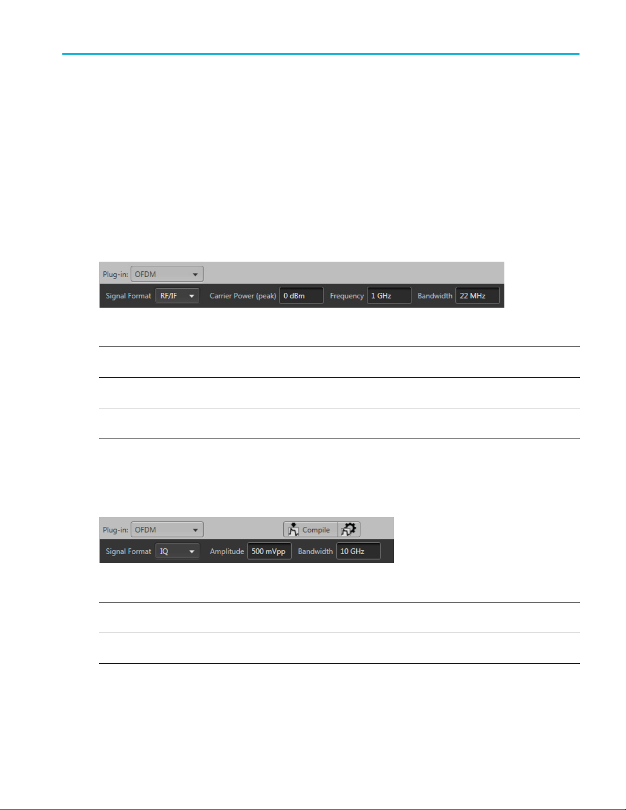
Basic setup
Signal format
selection
The Signal Format selection lets you choose the signal format type, either as RF signals (RF/IF) or
baseband sig
nals (IQ).
RF/IF
When set to RF/IF, the dialog screen change s to set the basic parameters for the RF/IF carrier. A single
waveform is created when compiling an RF/IF waveform.
Item Description
Carrier Power (peak) Enter the power of the carrier in dBm.
ge is –8.062 dBm to –2.041 dBm.
The ran
Frequency
idth
Bandw
xxx
he frequency of the carrier in Hz.
Enter t
The range is dependent on the instrument.
Enter the bandwidth of the carrier in Hz.
The range is 100 kHz to 10 GHz.
IQ
When set to IQ, the dialog screen changes to set the basic parameters for the IQ carrier. Two waveforms
are created when compiling IQ waveforms.
Item Description
Amplitude
Bandwidth
xxx
Enter the amplitude of the carrier in peak-to-peak volts.
The range is dependent on the instrument.
Enter the bandwidth of the carrier in Hz.
The range is 100 kHz to 10 GHz.
OFDM Plug-in Application Printable Help 9
Page 16

Basic setup Basic setup
10 OFDM Plug-in Application Printable Help
Page 17

Frames tab Frame settings
Frame settings
The Frames tab contains the basic frame settings. You can define up to 100 frames.
All frame settings are unique for each frame.
Item Description
Frame List
Add Frame button
OFDM Frame quick
access buttons
The Frames dialog area lists all the currently defined frames. You can define (add) up to 100
frames.
The Add Frame button inserts a new frame to the end of the list. The added frames are initially set
to Frame_#, where the # is i ncremented for each added frame.
To edit the frame name, double left-click on the name to enter the editing mode. Once in the editing
mode, you can also right-click to display the Cut, Copy, and Paste options.
To remove a frame, select the frame and ri ght-click to display the Remove option.
These buttons allow you to easily enable or disable the Preamble, Header, and Payload
configurations for each frame.
Initially, any new frame will have the Preamble, Header, and Payload enabled by default.
At least one must be enabled to compile a waveform.
Frame Spacing Specify the spacing between the frame in seconds. An off-time waveform is automatically created
in addition to the carrier waveform during compile.
Enabling Frame Spacing also enables the Off-Time Noise setting.
Off-Time Noise Specify noise in dB for the off-time duration. A Noisy off-time waveform is created when this
is enabled.
This is available only when using Frame Spacing.
Window
xxx
Select the overlap window type from the following: None, Triangular, Kaiser, Hanning, Hamming,
and Blackman.
This is used to shape the spectrum of header and payload symbols.
OFDM Plug-in Application Printable Help 11
Page 18

Frames tab Preamble tab
The secondary tabs on the Frames tab allow you to continue setting carrier parameters that are unique to
each frame.
See the following topics.
Preamble tab (see page 12)
Header tab (see page 13)
Payload tab (see page 13)
ab
Multipath t
(see page 14)
Gated Noise tab (see page 15)
Hopping tab (see page 16)
Phase Noise tab (see page 17)
Preamble tab
Click Turn On to enable the frame preamble. This can also be enabled and disabled from the OFDM
Frame quick set buttons.
Enable one (or both) of the Preamble selections to define the path to a saved preamble file. You can enter
the p ath directly or use the folder icon to navigate to your saved file.
For each frame, you can use either or both preamble files. Based on the different standard needs, there can
be multiple preamble requirements. Two preambles are supported in the OFDM plug-in application.
em
It
Domain
Frequency
Time
Repeat
scription
De
ecify data in Frequency domain or Time domain.
Sp
reamble data can be specified in the Frequency domain.
P
reamble data can be specified in the Time domain.
P
Specify the repeat value, which defines the number of times Preamble is repeated.
12 OFDM Plug-in Application Printable Help
Page 19

Frames tab Header tab
Item Description
Subcarriers Spacing Subcarrier spacing defines the separation of each carrier in the frequency domain description
of the Preambl
Sampling Rate Specify the sa
xxx
e data.
mpling rate for the data in the Preamble file.
Header tab
Click Turn On to enable the header. This is can also enabled and disabled from the OFDM Frame quick
set buttons
.
Item Description
File
Domain
Repeat
Subcarriers
Spacing
Sampling Rate Specify the sampling rate for the data in the Header file.
Symbols Select Symbols to insert de fined symbols into the table.
Symbols Select a row to insert a user defined symbol. A dialog box is presented to allow you the select
Repeat
xxx
Payload tab
Click Turn On to enable the payload. This is can also enabled and disabled from the OFDM Frame
quick set buttons.
Select file to use a predefined header file.
Chose how the header file is structured in the Frequency domain or Time domain.
Two-sided spectrum is assumed for Frequency domain.
Specify the repeat value, which defines the number of times Header is repeated.
Subcarrier spacing defines the separation of each carrier in the frequency domain description
of the H eader data.
the symbol to insert.
The symbols must first be defined in the Symbols tab
Specify the repeat value, which defines the number of times the symbol is repeated.
(see page 21).
OFDM Plug-in Application Printable Help 13
Page 20

Frames tab Multipath tab
Item Description
Symbols Select a row to insert a user defined symbol. A dialog box is presented to allow you the select
the symbol to insert.
(see page 21).
xxx
Repeat
The symbols must first be defined in the Symbols tab
Specify the repeat value, which defines the number of times the symbol is repeated.
Multipath tab
Click Turn On to enable m ultipath.
Multipath can be used to simulate the reflected signals which arrive with different delays.
You c a
path. No two paths can have the same delay value.
ndefine a maximum of ten multipaths, setting the delay, amplitude and phase values for each
14 OFDM Plug-in Application Printable Help
Page 21

Frames tab Gated Noise tab
Item Description
Delay
Amplitude
Phase
xxx
Gated Noise tab
ClickTurnOntoenablegatednoise.
When Complete Frame is selected, the signal to noise level (SNR) is set equally across the entire frame
(Preamble, Header, and Payloade).
Enter the delay in seconds from the reference path. The delay must be positive. Delay values
cannot be repeated.
Enter the amplitude in dB from the reference path. The amplitude for each path can be set to
zero dB or reduced.
Enter the phase in degrees from the reference path. The phase can be positive or negative.
When Custom is selected, you can add gated noise to each component of the frame and define the SNR for
each component.
OFDM Plug-in Application Printable Help 15
Page 22

Frames tab Hopping tab
Hopping tab
Click Turn On to enable hopping.
Hopping allows you to add frequency and amplitude hopping for a selected carrier.
Frequency hopping can be used to create frequency agile waveforms. Frequency hopping is used in
electronic counter measures by rapidly switching the frequency of the transmitted energy, and receiving
only that frequency during the receiving time window.
Item Description
Hop Time Hopping times a re based on the Frequency Hop List.
Select the method to define the Hop Time:
Symbol Start Index
Symbols Per Hop
Symbol Start
Index
Defines the index the specific hop starts. Each hop must contain a unique start index.
16 OFDM Plug-in Application Printable Help
Page 23

Frames tab Phase Noise tab
Symbols Per Hop
Symbols per Ho
field
Repeat List
xxx
p
Symbols per Ho
the entire hop pattern.
Range: 1 to 5000000.
Frequency (not available for IQ signal format)
Relative Frequency
Amplitude
When the Repeat List is enabled, the relative frequency and amplitude offset values are repeated.
p determines how many Symbols occur between each Hop. The value applies to
Phase Noise tab
ClickTurnOntoenablephasenoise.
Choose to enter the phase noise description using Time Model or Frequency Model. You can control the
phase noise property in terms of its magnitude and spectral content using either one of these models.
OFDM Plug-in Application Printable Help 17
Page 24

Frames tab Phase Noise tab
Item Description
Profile Choose one of the phase noise profiles from the pull-down list.
0
1/f
1
1/f
2
1/f
4
1/f
VCO Bandwidth Specify the bandwidth (VCO cutoff) for the selected profile. This field is not available if the
selected profile is 1/f0.
Phase Noise
xxx
Specify the phase in degrees for the selected profile.
Time Model
Item Descr
e
Profil
1/f0
1/f2
1/f3
1/f4
andwidth
VCO B
Spec
selected profile is 1/f0.
se Noise
Pha
xxx
Specify the phase in degrees for the selected profile.
iption
ify the bandwidth (VCO cutoff) for the selected profile. This field is not available if the
18 OFDM Plug-in Application Printable Help
Page 25

Frames tab Phase Noise tab
Frequency Model
Item Description
Bandwidth Type
Select either Auto, Frequency, or Level as the Bandwidth Type.
Level
Frequency
Auto
xxx
Specify t
Specify
he cut-off level for bandwidth consideration.
the frequency to be considered as the bandwidth for phase noise power spectral density.
In this mode, bandwidth is selected based on the system sampling rate and a predefined power
spectral density level of -180 dBc/Hz.
OFDM Plug-in Application Printable Help 19
Page 26

Frames tab Phase Noise tab
20 OFDM Plug-in Application Printable Help
Page 27
Symbols tab Symbols tab
Symbols tab
Use the Symbols tab to create and define symbols. Each symbol is unique with different settings.
At least one symbol is present in the symbol tab. Click Add to add a symbol to the table. To rename a
symbol, select the symbol, double-click it and type a name.
The symbols defined here are then available for selection in the Frames Payload tab
(see page 13).
OFDM Plug-in Application Printable Help 21
Page 28

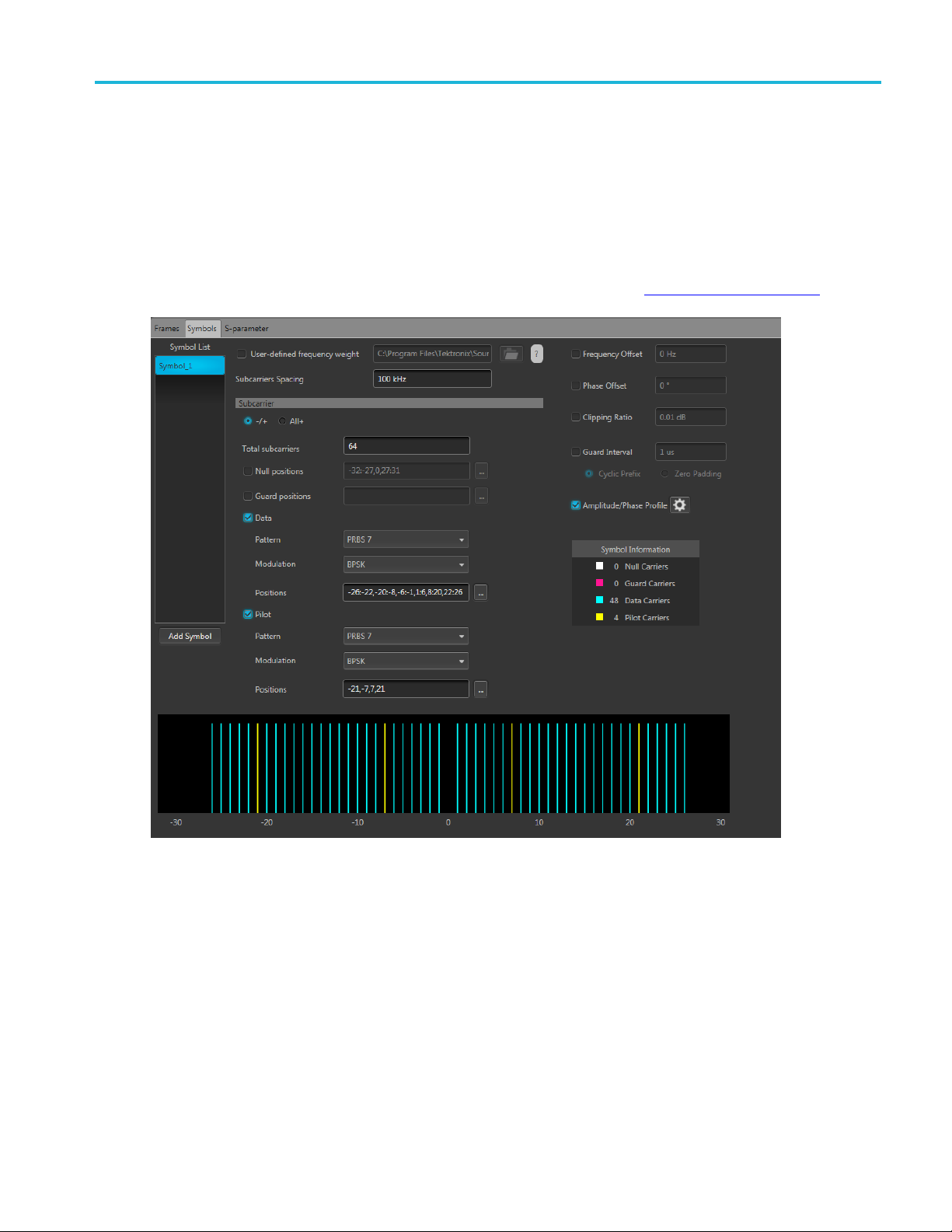
Symbols tab Subcarriers for symbols
Item Description
User-defined
frequency wei
Subcarriers
Frequency Offset If enabled, then specify the frequency offset value for the selected symbol.
Phase Offset If enabled, then specify the phase offset value for the selected symbol.
Clipping Ratio If enabled, then specify the Clipping Ratio value for the selected symbol. Clipping Ratio is the
Guard Interval This is used to reduce inter-symbol interference and reducing fading due to the frequency selective
Amplitude Phase
Profile
arrier
Subc
xxx
ght
Spacing
Specify the file from which to load symbol data. You still have to specify the Subcarrier spacing.
Additionally
Amplitude/Phase Profile to the symbol.
The Subcarrier parameter selections are disabled when using a user defined file.
A two-sided s
Enter the fre
The maximum value is dependent on carrier bandwidth (BW). Range is from 1 Hz to carrier
bandwidth.
Clip power level d ivided by Average Power.
nature o
Cyclic Prefix
Zero Padding
Select to turn on the profile.
Use the settings icon
See th
The s
See the Subcarriers
, you can add Frequency Offset, Phase Offset, Clipping Ratio, Guard Interval, and an
pectrum is assumed for a frequency domain symbol description.
quency interval between carriers.
Min: 1 Hz
Max: Carrier B W value
f the channels.
to display the profile configuration display.
e topic Amplitude Phase Profile
ubcarrier section is not available when using a user-defined frequency weight.
(see page 22) for an explanation o f the settings.
(see page 27).
Subcarriers for symbols
The subcarrier section is not available when using a user-defined frequency weight.
22 OFDM Plug-in Application Printable Help
Page 29

Symbols tab Subcarriers for symbols
Item Description
–/+
All+
Total subcarriers
Null positions
Select – /+ to show both the negative and positive subcarriers in the display graph.
Select All+ to only show the positiv e subcarriers in the display graph.
Enter the number of carriers for each symbol.
A minimum of two carriers is required.
A maximum of 4096 carries is allowed but the number must be a multiple of two.
Enable the Null positions if you want to specify certain subcarriers as null carriers, then specify the
positions.
Double click inside the positions box to enter values directly.
Click the
Null carriers are colored white in the display graph.
Defining subcarrier positions
See
positions.
icon to display a text entry screen for easier entry.
(see page 26) for information on how to properly format the
OFDM Plug-in Application Printable Help 23
Page 30

Symbols tab Defining the Pattern
Item Description
Guard positions Enable Guard positions if you want to specif y certain subcarriers as guard carriers, then specify
the positions
Double click inside the positions box to enter values directly.
.
Click the
Guard carriers are colored fuchsia in the display graph.
See Defining subcarrier positions
positions.
Data and Pilot
subcarriers
Enable Data and Pilot subcarriers to specify these subcarriers.
Data carriers are colored blue in the d isplay graph.
Pilot carriers are colored yellow in the display graph.
Once enabled, you can specify the Pattern, Modulation, and Positions.
Pattern
Modulation
Positions
Data and Pilot subcarriers require a pattern selection. See Defining the Pattern
Data and Pilot subcarriers require a modulation selection. See Modulation types
Data and Pilot subcarriers require that you specify the positions of these carriers.
See Defining subcarrier positions
positions.
xxx
Defining the Pattern
Item Description
All One Sends a sequence of binary 1 symbols.
All Zero
File
PRBS Select the PRBS type from the following: 7, 9, 15, 16, 20, 21, 23, 29, 31, and User Defined.
Sends a sequence of binary 0 symbols.
Select the base data file to be used by entering the path o r browsing to the file. The supported
format is .txt.
icon to display a text entry screen for easier entry.
(see page 26) for information on how to properly format the
(see page 24).
(see page 25).
(see page 26) for information on how to properly format the
Pattern
xxx
To edit the bit sequence, select User Defined. This displays the PRBS Editor icon
display the PRBS Editor
(see page 25) dialog screen.
Enter a pattern of 0s and 1s up to a maximum of 256 digits in the text field that appears.
. Select to
24 OFDM Plug-in Application Printable Help
Page 31

Symbols tab PRBS Editor
PRBS Editor
This dialog box is displayed when clicking PRBS Editor icon when PRBS is set to User Defined for
the Data and Pilot pattern type. (Symbols tab).
PRBS sequences are generated by a feedback shift register. The number (#) following PRBS indicates the
length of the generating shift register. For instance, a shift register with 16 memory cells is required to
generate a PRBS 16 sequence. The pseudo-random sequence of a PRBS generator is determined by the
number of registers and the feedback.
Modu
OFDM Plug-in Application Printable Help 25
lation types available
Item Description
PSK BPSK, QPSK, 8PSK
QAM 8 QAM, 16 QAM, 32 Q AM, 64 QAM, 128 QA M, 256 QAM, 512 QAM, 1024 QA M
xxx
Page 32

Symbols tab Defining subcarrier positions
Defining subcarrier positions
Null, Guard, Data, and Pilot positions all need to be specified when enabled.
Proper format of the positions must be followed to avoid errors.
Double click inside a positions box to enter values directly. Or, click the icon to display a text
entry scree
Separate all positions (or ranges) with a single comma.
Define a range of positions with the use of colon.
Example:
–22:–19,12,20 selects the four positions from –22 through –19, then positions 12 and 20.
n for easier entry.
26 OFDM Plug-in Application Printable Help
Page 33

Symbols tab Amplitude Phase Profile
Amplitude Phase Profile
This feature enables the you to selectively apply attenuation and phase rotation on each subcarrier or each
type of subcarrier, such as pilot and data subcarriers.
Item Description
Fixed
Data
Pilot
Custom Selecting Custom enables the table editor.
xxx
Selecting Fixed allows you to enter the amplitude and phase for all data and pilot positions.
The data subcarrier (in the Symbols tab) must be enabled before you can choose to set the
data phase profile.
The pilot subcarrier (in the Symbols tab) must be enabled before you can choose to set the Pilot
phase profile.
With the custom table editor, you can specify the amplitude and phase for any carrier position.
See Defining subcarrier positions
positions.
(see page 26) for information on how to properly format the
OFDM Plug-in Application Printable Help 27
Page 34

Symbols tab Amplitude Phase Profile
28 OFDM Plug-in Application Printable Help
Page 35

S-Parameter tab S-Parameter license
S-Parameter license
A license is required to use the S-Parameter feature.
S-Parameters is available when a license is detected by the application. With the license installed on the
host PC where SourceXpress is installed, S-Parameters is available regardless of connecting to a virtual
generator or a real instrument.
Refer to Licensing
S-Parameter
Select Turn on to enable adding S-Parameters to the compiled waveforms.
S-Parameter parameters
S-Parameters can be applied to the RF/IF waveform or to the I and Q data, depending on the selected
Signal Format. All S-Parameter features apply whether the Signal Format is set to RF/IF or IQ. The only
ion is that an additional c ontrol is available for the IQ signal format to choose how the S-Parameters
except
are applied to the I and Q components. They can be applied to the individual I and Q components or to the
sameS-ParameterscanbeappliedtobothIandQ.
Below is a sample S-Parameter dialog screen with the Number of Ports set to 4 for an RF/IF . The dialog
screen changes to ac commodate the Number of Ports selected.
The available S-Parameter settings are identical regardless of the selected waveform.
information provided for S-Parameters applies to both the Non-Cascading and Cascading modes.
The
(see page 37) for information about obtaining a license file.
OFDM Plug-in Application Printable Help 29
Page 36

S-Parameter tab S-Parameter
Item Description
S-Parameter settings for
(Only available when IQ is the
d Signal Format.)
selecte
Use sam
(Only available when IQ is the
selected Signal Format.)
e settings for I and Q
Select I or Q to apply the S-Parameters to just that selection.
his box to apply the same S-Parameters to both I and Q.
Check t
CAUTION. When you select this setting, the Q parameters are instantly replaced
with the I parameters.
30 OFDM Plug-in Application Printable Help
Page 37

S-Parameter tab S-Parameter
Item Description
Mode
Select Non-Cascading or Cascading S-parameter mode.
In the Non-Cas
from only one S-parameter file.
cading mode, you apply S-parameter characteristics on the signal
De-embed
(Non-Cascading mode)
Cascading De-embed
(Cascading mode)
Bandwidth
In the Casca
apply the characteristics on the signal. You can select the files to apply by turning on
or turning off the corresponding Stages shown in the display. All the selected files
should be o
The files supported are s1p, s2p, s4p, s6p, s8p, and s12p.
Check the box to invert the S-Parameters from the signal. This removes the effects
of the component (for which the S-Parameters were created) from the signal path.
Auto – The bandwidth is defi ned at the point where the signal rolls off to -60 dB. If
this results in a bandwidth greater than the instrument supports, the bandwidth is set
to ½ of the waveform’s sample rate (i.e. Nyquist Frequency).
Full Bandwidth – The bandwidth is set to ½ of the waveform’s sample rate (i.e.
Nyquist Frequency).
Manual – The bandwidth can set by the user from 1 Hz to ½ of the maximum sample
rate of the instrument. If the set Bandwidth is greater than the Nyquist (Sample rate
of the waveform/2), then the software l imits the bandwidth to ½ of the waveform’s
sample rate. A warning message is provided.
ding mode, you can cascade up to six S-parameter files in Stages and
f the same type. The settings depend on the selected type of file.
OFDM Plug-in Application Printable Help 31
Page 38

S-Parameter tab S-Parameter
Item Description
Number of Ports Choose the number of ports. The port matrixes supported are 1, 2, 4, 6, 8, and 12.
orts selected determines:
rixes available
he Touchstone file to apply to the signal. The type of Touchstone files
ported are s1p, s2p, s4p, s6p, s8p, and s12p.
ded: If the data is single-ended, you must map the port numbers as used in
-Port).
S-Parameter
Signaling
(Only for 4, 8, and 12 ports)
Selection of the port
(Only for
File
Scheme
2, 4, and 6 ports)
The number of p
• The type of S-Parameter file to apply
• The Signaling Scheme choice
• The port mat
Navigate to t
that you are able to open is dependent on the number of ports selected. For instance,
only .s4p files can be opened if the Number of Ports is set to 4.
The files sup
Single-En
the file to physical locations in your link.
Differential: If the data is differential, you must select the data layout in the file.
Use the diagrams to map the ports for the transmitter ports (Tx-Port) and the receiver
ports (Rx
When choosing the number of Ports, you are presented with an active diagram of
the ports. The diagram presented reflects the Number of Ports selected and the
ng Scheme (if appropriate for the ports selected).
Signali
32 OFDM Plug-in Application Printable Help
Page 39

S-Parameter tab S-Parameter
Item Description
Victim
Aggressor and Both
(Only for 8 and
12 ports)
Victim: The default setting with no cross-talk effects.
Aggressor: Se
of cross-talk.
lect this to activate aggressor signal parameters, adding the effect
Port selection
xxx
arameter file descriptions
S-P
eractive area is available only when Number of Ports selection 2, 4, or
This int
6. You can select values for the transmitter ports (Tx-Port) and the receiver ports
(Rx-Port) for each stage.
1-port
Files with one port of data contain only one S-parameter file (s1p) so they do not require any further input.
OFDM Plug-in Application Printable Help 33
Page 40

S-Parameter tab S-Parameter
2-port
Files with data for two ports contain four S-parameters as a 2x2 matrix. These are Touchstone 2-port files
p). A dialog box is created to define the 2-port mapping.
(s2
4-Port
Files with data for four ports contain 16 S-parameters as a 4x4 matrix. These are Touchstone 4-port files
(s4p). They may contain single-ended or differential data. A dialog box is created to define the 4-port
mapping for either single-ended or differential data.
If the data is single-ended, you must map the port numbers as used in the file to physical locations in
your link.
You can select the port for both transmitter and receiver from the drop-down list. Each drop-down list
has ports from 1 to 2.
If the data is differential, you must select the data layout in the file.
6-port
Files with data for six ports contain 36 S-parameters as a 6x6 matrix. These are Touchstone 6-port files
(s6p). A dialog box is created to define the 6-port mapping.
8-Port
Files with data for eight ports contain 64 S-parameters as an 8x8 matrix. These are Touchstone 8-port files
(s8p). They may contain single-ended or differential data. A dialog box is created to define the 8-port
mapping for either single-ended or differential data.
If the data is single-ended, you must map the port numbers as used in the file to physical locations in
your link.
You can select the port for both transmitter and receiver from the drop-down list. Each drop-down list
has ports from 1 to 4.
If the data is differential, you must select the data layout in the file.
12-Port
Files with data for 12 ports contain 144 S-parameters as an 12x12 matrix. These are Touchstone 12-port
files (s12p). They may contain single-ended or differential data. A dialog box is created to define the
12-port mapping for either single-ended or differential data.
If the data is single-ended, you must map the port numbers as used in the file to physical locations in
your link.
You can select the port for both transmitter and receiver from the drop-down list. Each drop-down list
has ports from 1 to 6.
If the data is differential, you must select the data layout in the file.
34 OFDM Plug-in Application Printable Help
Page 41

S-Parameter tab S-Parameter
Aggressor signals
8 and 12 port S-parameters allows you to activate aggressor signal parameters and to add the effect of
cross-talk. 12 port S-parameters allows 2 Aggressor signal parameters.
Aggressors can be added in either Non-Cascading Mode or Cascading Mode.
The Ag
Item Description
Signal Choose the type of aggressor signal with the dropdown list:
Dat
gressor signal parameters include:
aRate
ck: Indicates that the aggressor signal is a clock pattern.
•Clo
• PBRS: Also choose the number of bits
• File: Indicates that the aggressor signal is another pattern file. Navigate to
Pattern file
the
• Same as victim: The signal flow of the aggressor is same as the victim.
Specify the data rate (in bps) of the signal.
This is not available when the Aggressor signal is set to be the same as the victim.
OFDM Plug-in Application Printable Help 35
Page 42

S-Parameter tab S-Parameter
Item Description
Aggressor Amplitude Enter the signal amplitude.
This is not available when the Aggressor signal is set to be the same as the victim.
Crosstalk Type Choose the type of crosstalk of the aggressor signal.
• Near-End Cro
• Far-End Crosstalk
• Both
xxx
sstalk
36 OFDM Plug-in Application Printable Help
Page 43

Licensing Licensing
Licensing
A license is required for this plug-in to become operational. The plug-in must be licensed for use with the
host application from where you want to use the plug-in.
For example, to use the plug-in from SourceXpress, SourceXpress must have a license. To use the plug-in
from an instrument, the instrument must have a license.
Refer to the application help (for either SourceXpress or the host instrument) for complete information
about obtaining and installing license files.
OFDM Plug-in Application Printable Help 37
Page 44

Licensing Licensing
38 OFDM Plug-in Application Printable Help
Page 45

Index
Index
A
Add Frame, 11
Aggressor, 3
amplitude phase profile, 27
Apply corrections file, 6
5
C
Compile, 4
Compile settings, 5
Correction file, 6
frequenc
y response, 6
D
Display elements, 3
Documentation, 2
Connected instrument, 2
Optical plug-in, 2
SourceXpress, 2
E
ents of the display, 3
Elem
F
frame spacing, 11
frame window, 11
frames
adding, 11
naming, 11
emove, 11
r
Frames, 11
Help menu, 8
hopping, 16
I
IQ, 9
K
Key features, 1
L
Licensin
g, 37
M
modulation types available, 25
multipath, 14
O
OFDM plug-in
description, 1
off-time noise, 11
P
tern, 24
pat
payload, 13
phase noise
settings, 17
Plug-in selection, 4
PRBS editor, 25
reamble, 12
p
Presets menu, 8
S
S-Parameter
file types, 33
S-Parameter license, 29
S-Parameters, 29
Aggressor, 33
Cascading
De-embed, 31
Differential, 32
Non-Cascading, 31
Number of Ports, 32
Selection of the port, 32
Signali
Single-Ended, 32
Victim, 33
Service support, 2
signal format, 9
subcarrier positions
form
subcarriers
settings, 22
subcarriers spacing, 13
Support information, 2
symbols
ttings, 21
se
symbols per hop, 17
,31
ng Scheme, 32
atting, 26
T
Technical support, 2
W
window, 11
G
gated noise, 15
H
header, 13
OFDM Plug-in Application Printable Help 39
R
Reset Plug-in, 8
RF/IF, 9
 Loading...