

Page 1

User Manual
OA 5000 Series
Optical Attenuators
070-7612-06
www.tektronix.com
Page 2

Copyright © Tektronix, Inc. All rights reserved.
Tektronix products are covered by U.S. and foreign patents, issued and pending. Information in this public ation supercedes
that in all previously published material. Specifications and price c hange privileges reserved.
Tektronix, Inc., P.O. Box 500, Beavert on, OR 97077
TEKTRONIX and TEK are registered trademarks of Tektronix, Inc.
Page 3

WARRANTY
Tektronix warrants that the products that it manufactures and sells will be free from defects in materials and
workmanship for a period of one (1) year from the date of shipment. If a product proves defective during this
warranty period, Tektronix, at its option, ei ther will repair the defective product without charge for parts and labor,
or will provide a replacement in exchange for the defective product.
In order to obtain service under this warranty, Customer must notify Tektronix of the defect before the expiration
of the warranty peri od and make suitable arrangements for the performance of service. Customer shall be
responsible for packaging and shipping the defective product to the service cente r designated by Tektronix, with
shipping charges prepaid. Tektronix shall pay for the return of the product to Customer if the shipment is to a
location within the country in which the Tektronix service center is located. Customer shall be responsible for
paying all shipping charges, duties, taxes, and any other charges for products returned to any other locations.
This warranty shall not apply to any defect , fa ilure or damage caused by improper use or improper or inadequate
maintenance and care. Tektronix shall not be obligated to furnish service under this warranty a) to repair damage
resulting from attempts by personnel other than Tektronix re presentative s to install, repair or service the product;
b) to repair damage resulting from improper use or connection to incompatible equipm ent; c) to repair any
damage or malfunction caused by the use of non-Tektronix supplies; or d) to service a product that has been
modified or integrated with other products when the effect of such modification or integration increases the time
or difficul ty of servicing the product.
THIS WARRANTY IS GIVEN BY TEKTRONIX IN LIEU OF ANY OTHER W ARRANTIES, EXPRESS
OR IMPLIED. TEKTRONIX AND ITS VENDORS DISCLAIM ANY IMPLIED WARRANTIES OF
MERCHANTABILITY OR FITNESS FOR A PARTICULAR PURPOSE. TEKTRONIX’
RESPONSIBILITY TO REPAIR OR REPLACE DEFECTIVE PRODUCTS IS THE SOLE AND
EXCLUSIVE REMEDY PROVIDED TO THE CUSTOMER FOR BREACH OF THIS WARRANTY.
TEKTRONIX AND ITS VENDORS WILL NOT BE LIABLE FOR ANY INDIRECT, SPECIAL,
INCIDENTAL, OR CONSEQUENTIAL DAMAGES IRRESPECTIVE OF WHETHER TEKTRONIX OR
THE VENDOR HAS ADVANCE NOTICE OF THE POSSIBILITY OF SUCH DAMAGES.
Page 4

Page 5

EC Declaration of Conformity
We
Tektronix UK Ltd.
The Arena
Downshire Way
Bracknell, RG12 1PU
declare under sole responsibility that the
OA5000 Series Optical Attenuators
OA5002, OA5012, OA5022, and OA5032
Including the OCP5502 Power Module
meet the intent of Directive 89/336/EEC for Electromagnetic Compatibility and
Low Voltage Directive 73/23/EEC for Product Safety.
Compliance was demonstrated to the following specifications as listed in the Official
Journal of the European Communities:
EMC Directive 89/336/EEC:
EN 61326 EMC requirements for Class A electrical equipment for
measurement, control, and laboratory use
IEC 61000--4--2 Electrostatic Discharge Immunity
(Performance Criterion B)
IEC 61000--4--2 RF Electromagnetic Field Immunity
(Performance Criterion A)
IEC 61000--4--2 Electrical Fast Transient / Burst Immunity
(Performance Criterion B)
IEC 61000--4--2 Power Line Surge Immunity
(Performance Criterion B)
IEC 61000--4--2 RF Conducted Immunity
(Performance Criterion A)
IEC 61000--4--2 Power Line Voltage Fluctuation Immunity
(Performance Criterion B)
EN 61000--3--2 AC Power Line Harmonic Emissions
This product meets the essential requirements in Annes 1 of the
Low Voltage Directive 73/23/EEC, amended by 93/68/EEC:
EN 61010--1/A1 Safety requirements for electrical equipment for
measurement, control, and laboratory use
Page 6

Page 7

Welcome
Congratulations on your purchase of an OA 5000 Series Optical Attenuator.
The OA 5000 Series Optical Attenuators are high-performance instruments
used to attenuate optical signals. The OA 5000 Series consists of four instruments, the OA 5002, OA 5012, OA 5022, and OA 5032. The major difference
between the models is the optical fiber connection. The OA 5002 is used
with single-mode fiber; the OA 5012, with 50 m multimode fiber; the
OA 5022, with 62.5 m multimode fiber; and the OA 5032, with 100 mfiber.
Some of the outstanding characteristics of the OA 5000 Series are:
H Attenuation to 60 dB — the OA 5000 can attenuate signals up to 60 dB
in steps of 0.01 dB. A shutter provides greater than 100 dB attenuation
for the OA 5002, OA 5012, and OA 5022. The shutter provides greater
than 90 dB attenuation for the OA 5032.
H 600 nm to 1700 nm calibrated spectral response in one unit.
H Linear response within ±0.05 dB.
H Ability to store attenuation levels, which is useful for repeat measure-
ments.
H GPIB Programmable — the OA 5000 Series conforms to IEEE Std 488.2.
H Models for both Single and Multimode Fiber.
OA 5000 Series User Manual i
Page 8

Welcomeii
Page 9

A Quick Tour
Contents
Welcome i...................................................
Contents iii...................................................
List of Figures vii..............................................
List of Tables viii...............................................
Safety ix......................................................
Installation 1-1.................................................
Removing the OA 5000 1-2..................................
A Quick Tour 1-3...............................................
Preset the OA 5000 1-3......................................
Storing and Recalling Settings 1-4...........................
Setting a Reference Value 1-5................................
User Reference
Operator Overview 2-1..........................................
The User Reference Section 2-1.............................
Enabling/Disabling Attenuation 2-3..............................
Setting Attenuation Levels 2-5...................................
Specifying the Wavelength 2-5...............................
Setting the Attenuation Level 2-6.............................
Setting the Attenuation Level to Minimum 2-7.................
Setting the GPIB Address 2-9...................................
Setting the Reference Level 2-11.................................
Measuring Insertion Loss 2-12................................
Approximating Signal Power 2-13.............................
Storing and Recalling
Attenuation Levels 2-15......................................
OA 5000 Series User Manual iii
Page 10

Programming
Setting Up the Instrument 3-1...................................
Controllers 3-1.............................................
Using the GPIB Interface 3-1.................................
Command Syntax 3-5...........................................
Clearing the OA 5000 3-5....................................
Command and Query Structure 3-6..........................
Command Entry 3-8.........................................
Argument Types 3-10.........................................
Syntax Diagrams 3-11........................................
Commands 3-13.................................................
Common Commands and Queries 3-13........................
Device Commands and Queries 3-14..........................
ADJusting? (Query Only) 3-15................................
ALLev? (Query Only ) 3-15....................................
ATTenuation 3-16............................................
BLRN 3-17...................................................
*CAL? (Query Only) 3-18.....................................
*CLS (No Query Form) 3-18..................................
DESE 3-19...................................................
DISable 3-20................................................
DISPlay 3-20................................................
*ESE 3-21...................................................
*ESR? (Query Only) 3-22.....................................
EVEnt? (Query Only) 3-22....................................
EVMSG? (Query Only) 3-23...................................
EVQty? (Query Only) 3-23....................................
FACTORY (No Query Form) 3-24..............................
HEADer 3-25................................................
*IDN? (Query Only) 3-26.....................................
*LRN? or SET? 3-26..........................................
*OPC 3-27...................................................
*PSC 3-27...................................................
RECall (No Query Form) 3-28.................................
REFerence 3-29..............................................
*RST (No Query Form) 3-29..................................
*SRE 3-30...................................................
*STB? (Query Only) 3-31.....................................
STORe (Store Attenuation) 3-31...............................
*TST? (Query Only) 3-32.....................................
VERBOSE 3-33..............................................
*WAI (No Query Form) 3-34...................................
WAVelength 3-34.............................................
Welcomeiv
Page 11

Appendices
Status and Events 3-35..........................................
Registers 3-35...............................................
Queues 3-39.................................................
Event Handling Sequence 3-39................................
Conflicts 3-40................................................
Messages 3-41..............................................
Appendix A: Accessories A-1....................................
Standard Accessories A -1...................................
Optional Accessories A-1....................................
Appendix B: Specifications A-3..................................
Appendix C: Interface Specifications A-7.........................
Interface Messages A-7.....................................
Character Set (ASCII Chart) A-8..............................
GPIB Function Subsets A-9..................................
Appendix D: Using the *OPC Query/Command A-11................
Appendix E: Packing for Shipment A-13...........................
Appendix F: Maintenance A-15....................................
Cleaning the Optical Ports A-15...............................
Changing the Optical Port Connectors A-17....................
Appendix G: Product Verification A-21.............................
Equipment List A-21..........................................
Power Up A-22...............................................
Display Modes A-23..........................................
GPIB Address Setting A-24...................................
Attenuation Range A-24......................................
Shutter Attenuation and the DISABLE button A-25..............
1310 nm: Insertion Loss, Attenuation Accuracy, a nd
Repeatability A-26........................................
1550 nm: Insertion Loss, Attenuation Accuracy, a nd
Repeatability A-28........................................
850 nm (except A5002): Insertion Loss, Attenuation
Accuracy, and Repeatability A-29..........................
Appendix H: Replaceable Parts A-31..............................
Parts Ordering Information A-31...............................
Using the Replaceable Parts List A-31.........................
OA 5000 Series User Manual v
Page 12

Index
Index I-1......................................................
Welcomevi
Page 13

List of Figures
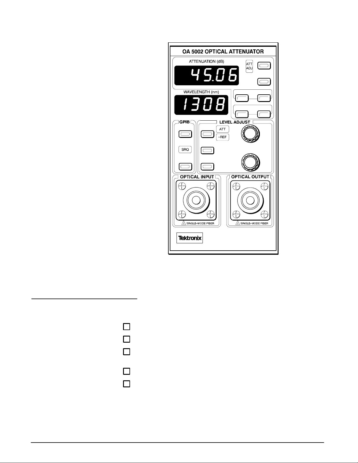
Figure 1-1: Installing the OA 5000 into the Power Module 1-2.........
Figure 1-2: OA 5002 Front Panel 1-4..............................
Figure 2-1: OA 5002 Front Panel 2-2..............................
Figure 2-2: The Location of the DISABLE Button 2-3................
Figure 2-3: Setting Attenuation Levels 2-5..........................
Figure 2-4: The Location of the ADDR (SET) Button 2-9..............
Figure 2-5: The Location of the SET REF Button 2-11.................
Figure 2-6: The Location of the STORE and RECALL Buttons 2-15.....
Figure 3-1: GPIB Connector Location 3-2..........................
Figure 3-2: Typical GPIB Network Configurations 3-2................
Figure 3-3: Command Message Elements 3-6......................
Figure 3-4: Block Argument Example 3-10..........................
Figure 3-5: Typical Syntax Diagrams 3-11...........................
Figure 3-6: The Standard Event Status Register (SESR) 3-35..........
Figure 3-7: The Status Byte Register (SBR) 3-36.....................
Figure 3-8: The Device Event Status Enable Register (DESER) 3-37....
Figure 3-9: The Event Status Enable Register (ESER) 3-38............
Figure 3-10: The Service Request Enable Register (SRER) 3-38.......
Figure 3-11: Status and Event Handling Process 3-40................
Figure A-1: Removing the Optical Bulkhead Connector A-16..........
Figure A-2: FC Optical Bulkhead Assembly A-17.....................
Figure A-3: ST Optical Bulkhead Assembly A-18.....................
Figure A-4: DIN 47256 Optical Bulkhead Assembly A-18..............
Figure A-5: SC Optical Bulkhead Assembly A-19.....................
Figure A-6: OA 5000 Replaceable Parts A-33........................
OA 5000 Series User Manual vii
Page 14

List of Tables
Table 3-1: B NF Symbols and Meanings 3-5........................
Table 3-2: Command Message Elements 3-6......................
Table 3-3: Comparison of Header On and Off Responses 3-7.........
Table 3-4: Commands Common to All GPIB Devices and
Supported by the OA 5000 Series 3-13.........................
Table 3-5: OA 5000 Device Commands and Parameters 3-14.........
Table 3-6: FACTORY Front Panel Settings 3-24......................
Table 3-7: R esults from *TST? 3-32................................
Table 3-8: SESR Bit Functions 3-36................................
Table 3-9: SBR Bit Functions 3-37..................................
Table 3-10: No Event Messages 3-41...............................
Table 3-11: Command Error Messages — CME Bit 5 3-41............
Table 3-12: Execution Error Messages — EXE Bit 4 3-42.............
Table 3-13: Device Error Messages — DDE Bit 3 3-43................
Table 3-14: System Event Messages — QYE Bit 2 3-43...............
Table 3-15: Execution Warning Messages — EXE Bit 4 3-43..........
Table A-1: Optical Characteristics A-3.............................
Table A-2: Mechanical Characteristics A-4..........................
Table A-3: Environmental Performance A-4........................
Table A-4: OA 5000 Standard Interface Messages A-7..............
Table A-5: The ASCII Character Set A-8............................
Table 4-1: Equipment Required for Performance Verification A-21......
Table 4-2: Attenuation Accuracy at 1310 nm A-27....................
Table 4-3: Attenuation Accuracy at 1550 nm A-29....................
Table 4-4: Attenuation Accuracy at 850 nm A-30.....................
Welcomeviii
Page 15
Safety
You might be eager to begin using your OA 5000, but please take a moment
to review these safety precautions. They are provided for your protection
and to prevent damage to the Optical Attenuator. This safety information
applies to all operators and service personnel.
Symbols and Terms
These two terms appear in manuals:
H
statements identify conditions or practices that could result in
damage to the equipment or other property.
H
statements identify conditions or practices that could result in
personal injury or loss of life.
These two terms appear on equipment:
H CAUTION indicates a personal injury hazard not immediately accessible
as one reads the marking, or a hazard to property including the equip-
ment itself.
H DANGER indicates a personal injury hazard immediately accessible as
one reads the marking.
This symbol appears in manuals:
Static-Sensitive Devices
These symbols appear on equipment:
DANGER
High Voltage
OA 5000 Series User Manual ix
Protective
ground (earth)
terminal
ATTENTION
Refer to
manual
Page 16

Specific Precautions
Observe all of these precautions to ensure your personal safety and to
prevent damage to either the OA 5000 or equipment connected to it.
Optical Output
WARNING
T o prevent damage to your eyes, avoid looking into the optical
output port while there is an optical signal connected to the input
port. Even if the OA 5000 is switched off, light can pass through the
attenuator. Always attach the output port to a receiver before attaching the source signal to the input port.
Power Source
The OA 5000 is designed for operation in a Tektronix TM 5000 Series Power
Module or the right-hand slot of an Tektronix OCP 5502. To ensure safe
operation, follow all precautions listed in the instrument’s Operators Manual.
Do not attempt to operate the OA 5000 with any other power source.
Grounding the Optical Attenuator
The OA 5000 is grounded through the power module. To avoid electric
shock, plug the power module power cord into a properly wired receptacle
where earth ground has been verified by a qualified service person.
Without the protective ground connection, all parts of the OA 5000 are
potential shock hazards. This includes knobs and controls that may appear
to be insulators.
Use the Proper Power Cord
Use only the power cord and connector specified for your TM 5000 Series
Power Module. Use only a power cord that is in good condition.
Use the Proper Fuse
To avoid fire hazard, use only the fuse specified in the parts list for your
TM 5000 Series Power Module, and which is identical in type, voltage rating,
and current rating.
Do Not Remove Covers or Panels
To avoid personal injury, do not operate the OA 5000 or TM 5000 Series
Power Module without the panels or covers.
Safetyx
Page 17

Do Not Operate in Explosive Atmospheres
The OA 5000 provides no explosion protection from static discharges or
arcing components. Do not operate the OA 5000 in an atmosphere of explosive gasses.
OA 5000 Series User Manual xi
Page 18

Safetyxii
Page 19

A Quick Tour
Page 20

Page 21

Installation
The OA 5000 Optical Attenuator is designed to operate in a Tektronix
TM 5000 Series Power Module or the right -hand slot of a Tektronix
OCP 5502. To ensure safe operation, follow all precautions listed in the
Power Module’s Operator Manual. Do not attempt to operate the OA 5000
with any other power source.
Install the OA 5000 as follows:
Step 1: Plug the TM 5000 Power Module or OCP 5502 into an appropri-
ate AC power source.
CAUTION
To prevent possible instrument damage, make sure the power
module is turned off before inserting the OA 5000.
Step 2: After ensuring the power module is turned off, align the top and
bottom grooves of the OA 5000 with the rails of the power module (in
the right-hand slot of the OCP 5502) and slide the OA 5000 in until the
edge connector snaps into place. See Figure 1-1. The OA 5000 front
panel should be flush with the power module cabinet.
OA 5000 Series User Manual 1 --- 1
Page 22
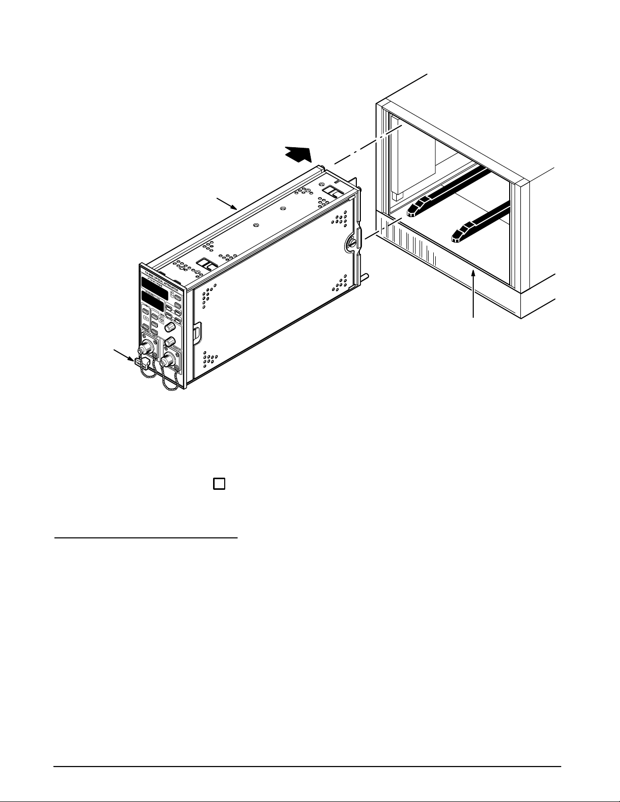
Installation
Release Lever
OA 5000
TM 5000 Series
Power Module
Removing the OA 5000
Figure 1-1: Installing the OA 5000 into the Power Module
If you will be programming the OA 5000 over the GPIB, perform the following
additional step:
Step 3: Attach the GPIB cable from your instrument controller to the
GPIB connector located on the back of the TM 5000 Power Module.
Before removing the OA 5000 from the power module, turn the power module off.
To remove the OA 5000 plug-in, grab the release lever and pull the instrument out.
1 --- 2
A Quick Tour
Page 23

A Quick Tour
This section provides a brief overview of the OA 5000 Optical Attenuator. The
overview illustrates how easy it is to learn about and use the OA 5000.
You can read this section or you can choose to investigate the OA 5000 on
your own. If you decide not to read the overview, refer to the User Reference
section to answer any questions you may have. User Reference also describes details and features not covered in this section.
In this section you will set up the OA 5000 and change various settings to
show get a feel for how the OA 5000 works. You will not be using any optical
signals.
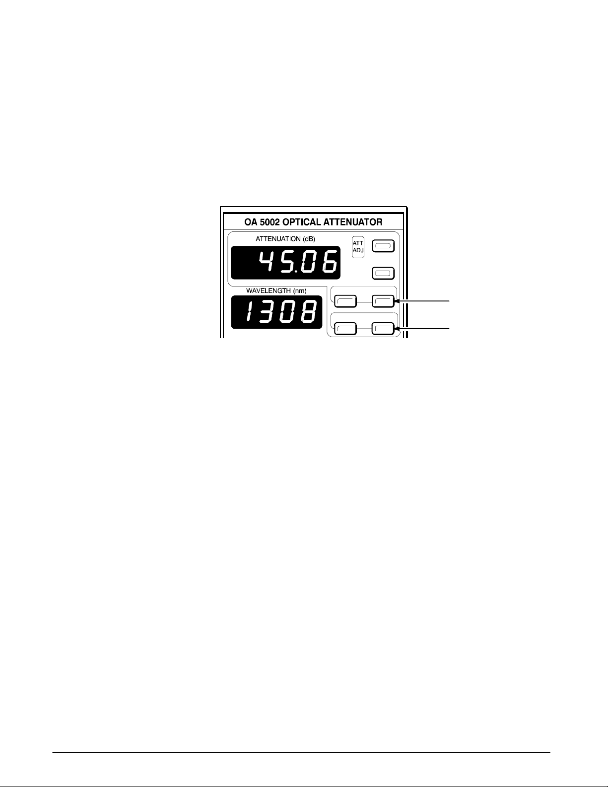
Figure 1-2, on page 1 --- 4, presents a front panel view of the OA 5000.
Preset the OA 5000
If you have not already done so, install the OA 5000 as described on
page 1--- 1 and turn on the instrument.
Step 1: Press MODE so that the ATT indicator is lit and -- REF is not lit.
This sets the OA 5000 to display attenuation in absolute units rather than
displaying attenuation relative to a reference value.
Step 2: Press WAVELENGTH. The word SET will appear in the attenua-
tion display.
Step 3: Using the COARSE and FINE knobs, set the WAVELENGTH to
1300 nm.
The actual attenuation of an optical input signal varies depending on the
wavelength of the signal. To ensure accurate attenuation readings, set
WAVELENGTH to the wavelength of the signal you are attenuating.
Step 4: Press WAVELENGTH again to accept the new wavelength
value.
Step 5: Press DISABLE,sothatitisnotlit.
If the DISABLE button is lit, the shutter inside the OA 5000 blocks the
signal path, providing ≥100 dB attenuation for the OA 5002, OA 5012,
and OA 5022, and ≥90 dB attenuation for the OA 5032. When the
DISABLE button is not lit, the shutter is withdrawn from the optical
signal path, enabling you to set the attenuation value from 0 to 60 dB in
0.01 dB increments.
Step 6: Press MIN ATT.
This sets the OA 5000 to 0 dB attenuation.
OA 5000 Series User Manual 1 --- 3
Page 24
A Quick Tour
DISABLE
MIN ATT
STORE 1 RECALL 1
STORE 2 RECALL 2
REMOTE MODE
Storing and Recalling Settings
ADDR
(SET)
SET REF
WAVE-
LENGTH
COARSE
FINE
Figure 1-2: OA 5002 Front Panel
Use the store and recall buttons to save one or two attenuator settings for
use at a later time.
Step 7: Using the COARSE knob, set the attenuation to 10.00 dB.
1 --- 4
Step 8: Store the attenuation setting by pressing STORE 1.
Step 9: Change the attenuation setting, using both the COARSE and
FINE knobs, to 21.50 dB.
Step 10: Store the attenuation setting by pressing STORE 2.
Step 11: Press MIN ATT and then press RECALL 1.
A Quick Tour
Page 25

A Quick Tour
Check the ATTENUATION readout and verify that it is set to 10.00 dB.
Step 12: Press RECALL 2.
Check the ATTENUATION readout and verify that it is set to 21.50 dB.
Setting a Reference Value
The SET REF button allows you to set a reference value for the attenuation.
You can then measure attenuation relative to this set value.
Step 13: Press MIN ATT.
This sets the OA 5000 to 0 dB attenuation.
Step 14: Press the SET REF button.
The word SET will appear in the wavelength display. The reference value
can now be adjusted with the COARSE and FINE knobs.
Step 15: Adjust the reference value for --- 8.00 dB using the COARSE
and FINE knobs.
Step 16: Press the SET REF button to accept the displayed value. The
display will return to normal.
Step 17: Press the MODE button.
Notice that the -- REF indicator is lit, indicating that the attenuation
display is now displaying attenuation relative to a reference value. The
attenuation display shows 8.00 dB and the MIN ATT button is lit.
Step 18: Using the COARSE knob, adjust the attenuation to 10.00 dB.
Step 19: Press the MIN ATT button. Check that the attenuation readout
has changed to 8.00 dB and the MIN ATT button is lit.
OA 5000 Series User Manual
The attenuation display reads 8.00 dB, instead of 0.00 dB, because the
display is still in reference mode and the reference value is (--- 8.00).
Pressing MIN ATT will set the OA 5000 to 0.00 dB only if the display is
not in reference mode or the reference value is 0.00 dB.
Step 20: Recall the first stored setting by pressing RECALL 1.
Remember that you set STORE 1 to 10.00 dB. Note that the attenuation
readout is 18.00 dB. The display shows the value: 10.00 --- (--- 8.00)=
18.00 dB.
1 --- 5
Page 26

A Quick Tour
Step 21: Recall the second stored setting by pressing RECALL 2.
Note that the attenuation readout is now 29.50 dB. Remember that you
set STORE 2 to 21.50 dB. The display shows the value: 21.50 ---
(--- 8.00)= 29.50 dB.
Step 22: Push the MODE button so that just the ATT indicator is lit, and
then push MIN ATT.
Notice that the ATTENUATION display is now 0.00, because you
pressed the MIN ATT button and the display is no longer in reference
mode.
Settings at Power Up
One last thing to note are the settings used at power up. When you power
down the OA 5000, it saves the attenuation setting, the mode, the wavelength, and reference levels. The next time you power up the OA 5000, it will
return to the settings stored when it was last powered down.
This completes the tour of the OA 5000.
1 --- 6
A Quick Tour
Page 27

User Reference
Page 28

Page 29

Operator Overview
The User Reference Section
The User Reference section is arranged as an alphabetic list of topics. Each
topic covers one aspect of the operation of the OA 5000. Five topics follow
this operator overview:
H Enabling/Disabling Attenuation
H Setting Attenuation Levels
H Setting the GPIB Address
H Setting the Reference Level
H Storing and Recalling Attenuation Levels
Figure 2-1, on page 2 --- 2, details the controls located on the OA 5000 front
panel.
NOTE
If, after power-up, the decimal points in the WAVELENGTH display
are flashing, the unit has lost its calibrator values and needs to be
recalibrated. Contact your local service center.
OA 5000 Series User Manual 2 --- 1
Page 30

Operator Overview
These lights indicate
whether the attenuation
display is in absolute
units or relative to a
reference value.
Pressing this button
generates a User
Request Event (URQ).
For more information,
see page 3 ---36. The
LED shows the
Remote/Local status. If
the LED is lit, the
OA 5000 is in remote
mode. If the LED is
flashing, the front
panel is locked out.
This button activates the
attenuation display
This light indicates that
the OA 5000 has
requested service from
the instrument
mode.
controller.
REMOTE MODE
SET REF
ADDR
(SET)
W A V E ---
LENGTH
STORE 1 RECALL 1
STORE 2 RECALL 2
COARSE
FINE
DISABLE
MIN ATT
When this indicator is lit, the
attenuation is being changed. When
it is dark, the set attenuation level
has been achieved.
The DISABLE button places
the shutter across the signal
path.
This button sets the
attenuation level to
minimum.
These buttons store
and recall attenuation
settings.
Use these knobs to
adjust the attenuation
level, the reference
level, the wavelength
setting, and the GPIB
address.
Use this button to assign the knobs
to set the GPIB address. The LED
is lit when the instrument is
addressed over the GPIB.
When this button is lit,
the knobs are
assigned to adjust the
Reference value.
When this button is lit, the
knobs are used to adjust the
wavelength setting.
Figure 2-1: OA 5002 Front Panel
2 --- 2
User Reference
Page 31
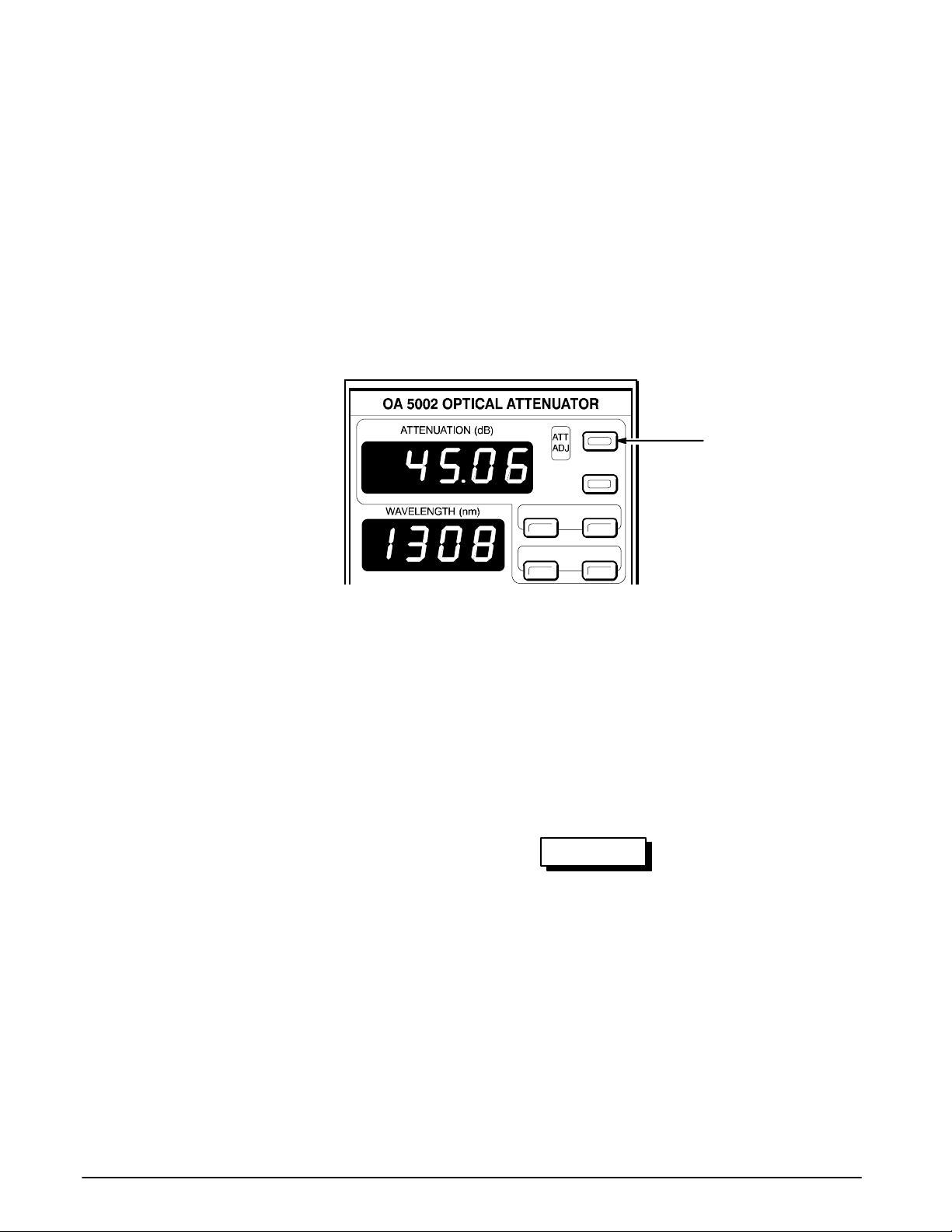
Enabling/Disabling Attenuation
On the OA 5000, the DISABLE button (Figure 2-2) allows you to enable or
disable the optical path through the attenuator with a shutter. You can still
set the attenuation level, however, since it is not dependent on the optical
signal passing through the attenuator. For example, you can block the
passage of the optical signal through the attenuator by disabling attenuation, setting the attenuation level, then enabling attenuation and your signal
will be attenuated to the desired level immediately.
DISABLE
This button enables or
MIN ATT
STORE 1 RECALL 1
STORE 2 RECALL 2
disables attenuation.
Figure 2-2: The Location of the DISABLE Button
To enable attenuation, press the DISABLE button on the front panel so that
the button is not lit. When the DISABLE button is not lit, the optical signal
passes through the attenuator.
To disable attenuation, press the DISABLE button so that it is lighted. When
the DISABLE button is lighted, the internal shutter is placed across the
optical path, providing ≥100 dB attenuation for the OA 5002, OA 5012, and
OA 5022, and ≥90 dB attenuation for the OA 5032.
WARNING
T o prevent damage to your eyes, avoid looking into the optical
output port while there is an optical signal connected to the input
port. The disable function is only valid while the instrument is
switched on. When the OA 5000 is switched off, the shutter withdraws from the optical path and the light is attenuated only by the
previous attenuator setting.
OA 5000 Series User Manual 2 --- 3
Page 32

Enabling/Disabling Attenuation
2 --- 4
User Reference
Page 33

Setting Attenuation Levels
Because the OA 5000 automatically adjusts the attenuator to correct for
different wavelengths, it is important, for attenuator accuracy, to correctly
match the displayed wavelength with the wavelength of the signal going into
the unit.
Setting attenuation levels on the OA 5000 requires you to perform two
procedures in the following order:
1. Specify the wavelength of the signal to be attenuated.
2. Set the level of attenuation.
Refer to Figure 2-3.
DISABLE
MIN ATT
This button sets
STORE 1 RECALL 1
attenuation to the
minimum
value.
This button assigns the
ATTENUATION display to
either absolute units or
units relative to the
Use this button to assign the
knobs to adjust the
Specifying the Wavelength
reference level.
wavelength.
STORE 2 RECALL 2
REMOTE MODE
ADDR
(SET)
SET REF
WAVE-
LENGTH
COARSE
FINE
These knobs set the
attenuation level,
reference level,
wavelength and GPIB
address.
Figure 2-3: Setting Attenuation Levels
To specify the wavelength to be attenuated:
Step 1: Press the WAVELENGTH button.
The word SEt will appear in the attenuation display and the WAVE-
LENGTH button will illuminate.
OA 5000 Series User Manual 2 --- 5
Page 34

Setting Attenuation Levels
Step 2: Use the two knobs to adjust the displayed wavelength value.
The COARSE knob changes the displayed value by 10 nm per click and
the FINE knob changes the displayed value by 1 nm per click. The
wavelength can be adjusted from 600 to 1700 nm.
Step 3: When the desired wavelength is displayed, press WAVE-
LENGTH again to accept the new displayed value. The OA 5000 will
return to the previous attenuation display mode.
Setting the Attenuation Level
To set the attenuation level once you have set the wavelength:
Step 1: Set the attenuation display mode by pressing the MODE but-
ton.
The attenuation display shows the current attenuation value in one of two
modes, absolute or relative to a reference value. Pressing the MODE button,
while it is illuminated, toggles between these modes.
When the ATT light is on and the -- REF light is off, the displayed attenuation
is in absolute mode. In this mode, the displayed attenuation is the value
relative to its absolute minimum setting. The minimum value in this mode is
always 0 dB.
When both the AT T and -- REF lights are on, the displayed attenuation value
is the absolute attenuation value minus the value of the reference (refer to
the section Setting the Reference Value to set the reference). The COARSE
and FINE knobs still adjust the attenuation value as with absolute mode.
The only difference is the value displayed in the attenuation display.
Step 2: Set the desired attenuation value by adjusting the COARSE
and FINE knobs. The COARSE knob changes the attenuation by 1 dB
per click and the FINE knob changes the attenuation by 0.01 dB per
click.
2 --- 6
NOTE
Switching between the absolute and relative display modes does
not change the actual attenuation value but only the value displayed.
User Reference
Page 35

Setting Attenuation Levels
Setting the Attenuation Level to Minimum
To set the attenuation level to minimum, press the MIN ATT button.
Setting the attenuation to minimum sets the absolute attenuation to 0 dB.
This means that the OA 5000 is not attenuating the optical input. However,
the attenuation display may not read 0 dB. As noted above, if the attenuation display mode is set to relative, the attenuation display will show the
absolute attenuation value (0 dB after pressing MIN ATT) minus the value of
the reference. If the reference value is non-zero, then the attenuation display
will not be 0 dB after pressing MIN ATT.
OA 5000 Series User Manual
2 --- 7
Page 36

Setting Attenuation Levels
2 --- 8
User Reference
Page 37

Setting the GPIB Address
Setting the GPIB address is accomplished using the ADDR (SET) button
and the LEVEL ADJUST knobs (Figure 2-4).
DISABLE
MIN ATT
STORE 1 RECALL 1
STORE 2 RECALL 2
REMOTE MODE
This button assigns
the knobs to set the
GPIB address.
ADDR
(SET)
SET REF
W A V E ---
LENGTH
COARSE
FINE
Turning either knob
changes the GPIB
address (when the
ADDR button is lit).
Figure 2-4: The Location of the ADDR (SET) Button
To set the GPIB address:
Step 1: Press the ADDR (SET) button so that it is lighted. The ATTEN-
UATION display will change to read Addr and the GPIB address will be
displayed in the WAVELENGTH display.
Step 2: Use either the COARSE or FINE knobs to change the address.
Step 3: When the address is set, press the ADDR (SET) button again
to enter the change of address.
The ADDR (SET) button also indicates the addressed status of the OA 5000
from the GPIB (when the GPIB address is not being set). When the button is
lit, the OA 5000 has been addressed to talk or listen by a controller on the
GPIB.
OA 5000 Series User Manual 2 --- 9
Page 38

Setting the GPIB Address
NOTE
Valid GPIB addresses are 0 through 30. If the GPIB address is
increased past 30, the display will show the word “OFF.” If OFF is
entered as the address, the OA 5000 will not be addressable over
the GPIB and it will not participate in any GPIB transactions.
2 --- 1 0
User Reference
Page 39

Setting the Reference Level
You can set the display of the OA 5000 to reflect the attenuation of the
system rather than just the attenuation provided by the OA 5000. For example, if your system insertion loss is 1.55 dB, you could set the reference
value to ---1.55 dB and the attenuation displayed would range from 1.55 dB
to 61.55 dB, instead of 0 dB to 60 dB.
Use the following procedure to set the reference level:
Step 1: Press SET REF so that it is lit (Figure 2-5).
Step 2: Adjust the reference level using the knobs.
Step 3: After setting the reference level, press the SET REF button
again.
DISABLE
MIN ATT
STORE 1 RECALL 1
STORE 2 RECALL 2
REMOTE MODE
ADDR
(SET)
SET REF
WAVE-
LENGTH
COARSE
This button assigns
the knobs to set the
Reference Level.
FINE
Figure 2-5: The Location of the SET REF Button
Once you have set the reference level, you may wish to change the attenuation display mode. To set the display mode so that the reference level is
subtracted from the attenuation provided by the OA 5000, press the MODE
button so that the -- REF indicator is lighted.
OA 5000 Series User Manual 2 --- 1 1
Page 40

Setting the Reference Level
The reference mode has two primary applications:
1. Reading total attenuation (insertion loss)
2. Approximating signal power
Measuring Insertion Loss
The total attenuation of any attenuator is the sum of the attenuation caused
by the connections (the insertion loss) and the attenuation caused by the
active element. Since the insertion loss is dependent on many factors, it is
hard to determine this value precisely. Some of the factors that affect insertion loss are the condition of the connectors, the cleanliness of the connectors, and the mode pattern of the fiber. Nonetheless, you can measure
insertion loss.
Step 1: Connect a stable source to an optical power meter using two
optical cables that have been joined with an in-line adapter.
Step 2: Measure the power on a suitable optical power meter and
measure the optical power in dBm.
Step 3: Disconnect the cables at the in-line adapter and connect them
to the optical attenuator (which should be set at minimum attenuation).
Step 4: Measure the resultant power in dBm.
The insertion loss (within the connector uncertainty) is the difference between the power reading with only the optical cables and the reading with
the cables plus the attenuator. The insertion loss specification for the
OA 5000 attenuators is ≤2.0 dB. The total attenuation is the insertion loss
plus the attenuation level shown on the OA 5000. Thus, by setting the reference level to the value of the insertion loss and enabling the reference
display mode, the OA 5000 can display the total attenuation of the attenuation system.
2 --- 1 2
User Reference
Page 41

Setting the Reference Level
Approximating Signal Power
The second application for reference mode is approximating signal power
after the source has been attenuated.
Step 1: Set the attenuator to its minimum reference level.
Step 2: Measure the power (in dBm) from the fiber connected to the
output optical connector.
Step 3: Set the reference value to this number.
Once this level has been set and the OA 5000 is in reference mode, the
displayed attenuation is the negative of the power level in dBm. For example, if the power level is --- 2.5 dBm when the attenuator is at its minimum
attenuation level and this is entered as the reference level, then the display
will read 2.5 dB when set to REF mode. Then, if you increase the attenuation
by 10 dB, the display will read 12.5, which is the negative of the power level
in dBm.
OA 5000 Series User Manual
2 --- 1 3
Page 42

Setting the Reference Level
2 --- 1 4
User Reference
Page 43
Storing and Recalling
Attenuation Levels
The OA 5000 can store two attenuation levels for later recall. This can help
save you time and minimize mistakes. Refer to Figure 2-6.
DISABLE
MIN ATT
STORE 1 RECALL 1
These buttons store
STORE 2 RECALL 2
Figure 2-6: The Location of the STORE and RECALL Buttons
and recall attenuation
settings.
To store an attenuation setting
H press either STORE1 or STORE2.
The current attenuation setting will be stored. The ATTENUATION display
will blink once to indicate acceptance of the value.
NOTE
When you press ST ORE1 or STORE2, the only setting s aved is the
attenuation setting. The wavelength setting is not stored. If the
wavelength of your signal has changed since the attenuation setting
was stored, you will have to adjust the wavelength setting to ensure
accurate attenuation.
To recall an attenuation setting
H press either RECALL1 or RECALL2.
The selected setting will be recalled.
OA 5000 Series User Manual 2 --- 1 5
Page 44

Storing and Recalling Attenuation Levels
2 --- 1 6
User Reference
Page 45

Programming
Page 46

Page 47

Setting Up the Instrument
This section tells you how to prepare the OA 5000 Optical Attenuator for use
with a remote controller or computer. The first part of this section explains
how to connect the OA 5000 to a controller or computer through the GPIB
interface. The rest of the section describes how to use the OA 5000 front
panel settings to enable the OA 5000 to send and receive messages to and
from a remote controller.
NOTE
In addition to the information in this manual, you will need to consult the documentation for your controller to determi ne how to send
commands, send interface messages such as local lockout and
serial poll, and receive query responses from within the programming language running on your controller or computer. Also, you
will need to determine how to assert various GPIB lines, including
remote enable and attention from within the programming language running your controller or computer.
Controllers
Using the GPIB Interface
You can control the OA 5000 with a remote controller or computer that uses
the IEEE Std 488.1-1987 (GPIB) interface.
The OA 5000 is connected to the GPIB through the TM5000 Series power
module in which it is installed. Connect the TM5000 power module to the
GPIB using an IEEE Std 488 GPIB cable (available as Tektronix part number
012-0991-00). The TM5000 power module has a 24-pin GPIB connector on
its rear panel (Figure 3-1). This connector has a D -type shell and conforms
to IEEE Std 488.
You can also stack GPIB connectors.
OA 5000 Series User Manual 3 --- 1
Page 48

Setting Up the Instrument
GPIB Connector
Figure 3-1: GPIB Connector Location
GPIB Requirements
Observe these rules when using your OA 5000 with a GPIB network:
H Each device on the bus must be assigned a unique device address; no
two devices can share the same device address.
H Do not connect more than 15 devices to any one bus.
H Connect one device for every 6 feet (2 meters) of cable used.
H Do not use more than 65 feet (20 meters) of cable to connect devices to
abus.
H At least two-thirds of the devices on the network must be turned on
while the network is operating.
H Connect the devices on the network in a star or linear configuration as
shown in Figure 3-2. Do not use loop or parallel configurations.
GPIB Device
GPIB Device
GPIB Device
GPIB Device
GPIB Device
GPIB Device
GPIB Device
Figure 3-2: Typical GPIB Network Configurations
3 --- 2
Appendix C, Interface Specifications, gives additional information on the
OA 5000 GPIB configuration.
Programming
Page 49

Setting Up the Instrument
Setting the GPIB Address
Once you have connected the OA 5000 through the GPIB interface, you
need to set its GPIB address to allow it to communicate through the interface.
To set the GPIB address:
Step 1: Press the ADDR (SET) button so that it is lighted. The ATTEN-
UATION display will change to read Addr and the GPIB address will be
displayed in the WAVELENGTH display.
Step 2: Use either the COARSE or FINE knobs to change the address.
Step 3: When the address is set, press the ADDR (SET) button again
to enter the change of address.
Once you have set the address, you can control the OA 5000 through the
GPIB interface.
OA 5000 Series User Manual
3 --- 3
Page 50

Setting Up the Instrument
3 --- 4
Programming
Page 51

Command Syntax
You can control the OA 5000 through the GPIB using a large group of commands and queries. This section describes the syntax these commands and
queries use and the conventions the OA 5000 uses to process them. The
commands and queries themselves are listed in the section entitled Commands.
You transmit commands to the OA 5000 using the enhanced American
Standard Code for Information Interchange (ASCII) character encoding.
Appendix C includes a chart of the ASCII character set.
This manual uses Backus-Naur Form (BNF) notation and syntax diagrams to
describe commands and queries. The syntax diagrams follow the notations
and conventions of the ANSI/IEEE Std 488.2-1987, section 7.2.
This manual uses the following BNF symbols listed in Table 3-1.
Table 3-1: BNF Symbols and Meanings
Clearing the OA 5000
Symbol
<> Defined element
::= Is Defined As
| Exclusive OR
{} Group; one element is required
[] Optional; can be omitted
... Previous element(s) may be repeated
() Comment
You can stop any query or process by using the Device Clear (DCL) GPIB
interface message.
Meaning
OA 5000 Series User Manual 3 --- 5
Page 52

Command Syntax
Command and Query Structure
Commands consist of set commands and query commands (usually simply
called commands and queries). Commands modify instrument settings or
tell the OA 5000 to take a specific action. Queries cause the OA 5000 to
return information about its status.
Most commands have both a set form and a query form. The query form of
the command is the same as the set form but with a question mark on the
end. For example, the set command ATT:DB has a query form ATT:DB?.
Not all commands have both a set and query form; some commands are set
only and some are query only.
A command message is a command or query name, followed by any information the OA 5000 needs to execute the command or query. Command
messages consist of three different element types, defined in Table 3-2 and
shownintheexampleinFigure3-3.
Table 3-2: Command Message Elements
Symbol
<Header> The basic command name. If the header ends with a
Meaning
question mark, the command is a query. The header
may begin with a colon (:) character; if the command is
concatenated with other commands the beginning colon
is required. The beginning colon can never be used with
command headers beginning with star (*).
<Mnemonic> A header sub-function. Some command headers have
only one mnemonic. If a command header has m ultiple
mnemonics, they are always separated from each other
by a colon (:) character.
<Argument> A quantity, quality, restriction, or limit associated with the
header. Not all commands have an argument, while
other commands have multiple arguments. Arguments
are separated from the header by one or more space
characters. Arguments are separated from each other
by a <Separator>, defined below.
<Separator> A separator between arguments of multiple-argument
commands. The separator can be a single comma, or it
may optionally have white space characters before and
after the comma.
Header
ATT:DB 10
Mnemonics
Argument
3 --- 6
Figure 3-3: Command Message Elements
Programming
Page 53

Command Syntax
Commands
Commands cause the OA 5000 to perform a specific function or change one
of its settings. Commands have the structure:
H [:]<Header>[<Space><Argument>[<Separator><Argu-
ment>]...]
Queries
Queries cause the OA 5000 to return information about its status or settings.
Queries have the structure:
H [:]<Header>?
H [:]<Header>?[<Space><Argument>[<Separator><Argu-
ment>]...]
You may use only a part of the header in a query command. When you do
this, the instrument returns information about all the possible mnemonics
that you have left unspecified. For example, ATT:DB? returns the current
setting in absolute dB units, while ATT? returns the setting in absolute units
and units relative to the reference.
Headers in Query Responses
You can control whether or not headers are returned by the OA 5000 as part
of the query response. Use the HEADER command to control this feature. If
header is on, command headers are returned as part of the query, and the
query response is formatted as a valid set command. When header is off,
only the values are sent back in the response, which may be easier to parse
and to extract the information. Table 3-3 shows the difference in responses.
Table 3-3: Comparison of Header On and Off Responses
Query
DISP? DB :DISP DB
ATT:DB? 32.53 :ATT:DB 32.53
Header Off Response Header On Response
OA 5000 Series User Manual
3 --- 7
Page 54

Command Syntax
Command Entry
H Enter commands in upper or lower case.
H Precede any command with blank characters. Blank characters include
any combination of the ASCII control characters 00 through 09 and 0B
through 20 hexadecimal (0 through 9 and 11 through 32 decimal).
H The OA 5000 ignores commands consisting of any combination of blank
characters, carriage returns, and line feeds.
Abbreviating Commands
Many OA 5000 commands can be abbreviated. These abbreviations are
shownincapitalsinthecommand’s listing in the Commands section. For
example, the command DISPlay can be entered simply as DISP or dis-
play.
If you use the HEADER command to have command headers included as
part of query responses, you can further control whether the returned headers are abbreviated or are full-length. The VERBOSE command lets you
control this.
Concatenating Commands
You can concatenate any combination of set commands and queries using
a semicolon (;). The OA 5000 executes concatenated commands in the
order received. Concatenating commands is useful when you want to avoid
events generated by conflicting settings — see Conflicts on page 3 --- 40.
When concatenating commands and queries you must follow these rules:
3. Completely different headers must be separated by both a semicolon
and by the beginning colon on all commands but the first. For example,
the commands ATT:DB 15 and DISABLE OFF would be concatenated
into a single command:
ATT:DB 15;:DIS OFF
4. Never precede a star (*) command with a colon:
ATT:DB 10;*OPC
5. When you concatenate queries, the responses to all the queries are
concatenated into a single response message. For example, if the
display mode is dB and the attenuator is 20 dB, the concatenated query
DISP?;:ATT:DB?
will return either DISP DB;:ATT:DB 20 if Header is set to on, or DB;20
if Header is set to off.
6. Set commands and queries may be concatenated in the same mes-
sage. For example:
ATT:DB 15;DISP DB;DIS?;:ADJ?
3 --- 8
Programming
Page 55

Command Syntax
is a valid message that sets the attenuation to 15 dB, the display mode
to dB, and responds with the disable status and the adjusting status.
Concatenated commands and queries are executed in the order re-
ceived.
Here are some invalid concatenations:
H DISPLAY DBR;ATT:DBR 5
no colon before ATT
H ATT:MIN;:*OPC
extracolonbeforeastar(*)command
Message Terminators
This manual uses <EOI> (End or Identify) to represent a message terminator.
Symbol Meaning
<EOI>
Message terminator
IfyouuseaGPIBnetwork,<EOI> can be the IEEE Std 488 EOI interface
symbol or LF (line feed). When using GPIB, the OA 5000 always accepts the
EOI interface symbol as an input message terminator.
The end-of-message terminator may be either the END message (EOI
asserted concurrently with the last data byte), the ASCII code for line feed
(LF) sent as the last data byte, or both.
The end-of message terminator should not immediately follow a semicolon
(;).
The OA 5000 always terminates responses to queries with linefeed and EOI
asserted.
OA 5000 Series User Manual
3 --- 9
Page 56

Command Syntax
Argument Types
The argument of a command may be in one of several forms. The individual
descriptions of each command tell which argument types to use with that
command.
Block Arguments
One OA 5000 command utilizes a block argument form:
Symbol Meaning
<Block>
<NZDig> A non-zero digit character, in the range 1 --- 9
<Dig> A digit character, in the range 0 --- 9
<DChar> A character with the binary equivalent of 0 through
The block argument is in the following format:
H <Block> ::= #<NZDig><Dig>[<Dig>. . .][<DChar>. . .]
<NZDig> specifies the number of <Dig> elements that follow. Taken togeth-
er, the <Dig> elements form a decimal integer that specifies how many
<DChar> elements follow.
A block of data bytes, defined below
FF hexadecimal (0 through 255 decimal)
Block Argument
BLRN #222(binary data - 22 bytes)
Block Header
Specifies Number of
Length Digits that Follow
Specifies Data Length
Figure 3-4: Block Argument Examp le
The block argument can also take the following format:
H <Block> ::= #0[<DChar>. . .]<EOI>
Under IEEE Std 488.2 this is also a valid form for block arguments. If this
form is used, the last byte of the block must have EOI asserted. Consequently, this must be the last or only command. Although the OA 5000
accepts this format, it will never respond to a query with this format.
Numeric Arguments
Many OA 5000 commands require numeric arguments. This manual represents these arguments as follows:
3 --- 1 0
Programming
Page 57
Symbol Meaning
Command Syntax
Syntax Diagrams
<NR1>
<NR2> Floating point value without an exponent
<NR3> Floating point value with an exponent
<NRf> Flexible numeric argument {NR1|NR2|NR3}. A suffix com-
The syntax diagrams in this manual use the following symbols and notation:
H Circles and ovals contain literal elements that must be sent exactly as
shown. Command and query names are abbreviated to the minimum
required spelling.
H Boxes contain the defined elements described earlier in this section,
such as <NRf> or <QString>.
H Arrows connect the elements and show the allowed paths through the
diagram. This also shows the different orders in which the elements can
be sent. Parallel paths show that one and only one of the paths must be
taken. A path around a group of elements shows that those elements
are optional. Loops show elements that can be repeated.
Signed integer value
posed of a multiplier (letter exponent) and units may be used
as an alternate to NR3. For example, this numeric type would
let you use “10nm” as an alternate to “10E--- 9m”
Figure 3-5 shows the structure of a few typical syntax diagrams.
Figure 3-5: Typical Syntax Diagrams
OA 5000 Series User Manual
3 --- 1 1
Page 58

Command Syntax
3 --- 1 2
Programming
Page 59

Commands
OA 5000 commands fall into two main groups: Common Commands and
Device Commands. The commands follow Tektronix Standard Codes and
Formats 1991.
Most of these commands can be used either as set commands or queries.
However, some commands can only be used to set: these have the words
“No Query Form” included with the command name. Other commands can
only be used to query: these have a question mark appended to the header,
and include the words “Query Only” in the command name.
Headers, mnemonics, and arguments are usually spelled out fully in text,
with the minimum required spelling shown in upper case. For example, to
use the command RECall you must enter at least REC. The examples in this
manual use the abbreviated forms.
Common Commands and Queries
Several commands and queries used with the OA 5000 are common to all
devices on the GPIB. These commands and queries are defined by IEEE
Std 488.2-1987 and Tektronix Standard Codes and Formats 1991 as useful
across all instruments in a GPIB system.
Table 3-4 lists the Common Commands supported by the OA 5000. Complete descriptions of these commands appear in an alphabetical listing of
commands later in this section.
Table 3-4: Commands Common to All GPIB Devices and
Supported by the OA 5000 Series
Header
ALLev? All Events
BLRN Binary Device Setup
1
*CAL?
*CLS Clear Status
DESE Device Event Status Enable
*ESE Standard Event Status Enable
*ESR? Standard Event Status Register
Full Command Name
Instrument Self Calibration
EVENT? Event
EVMSG? Event Message
EVQTy? Number of Events in Queue
OA 5000 Series User Manual 3 --- 1 3
Page 60

Commands
Table 3-4: Commands Common to All GPIB Devices and
Supported by the OA 5000 Series (Cont.)
Header Full Command Name
FACTory Set to Factory Defaults
HEADer Header
*IDN? Identification
*LRN? Learn Device Setup
*OPC Operation Complete
*PSC Power-On Status Clear
*RST Reset
*SRE Service Request Enable
*STB? Read Status Byte
*TST? Self-Test
Device Commands and Queries
VERBOSE Verbose
*WAI Wait To Continue
1
*CAL? always returns 0.
Table 3-5 lists the device commands, queries, and command parameters
that are specific to the OA 5000. Complete descriptions of these commands
appear in the alphabetical listing of commands that immediately follows this
table.
Table 3-5: OA 5000 Device Commands and Parameters
Header
Full Command Name
ADJusting? Attenuator Adjusting
ATTen Attenuation
ATTen:DB Attenuation in Absolute Terms
ATTen:DBR Attenuation with Reference Value
3 --- 1 4
ATTen:MIN Minimum Attenuation
DISable Light Shutter Status
DISPlay Front Panel Display Mode
RECall Recall Attenuation Setting
Programming
Page 61

ADJusting? (Query Only)
Commands
Table 3-5: OA 5000 Device Commands and Parameters (Cont.)
Header Full Command Name
REFerence Reference
STORe1|2 Store Attenuation
WAVelength Wavelength
The ADJusting? query returns the status of the attenuator. A 1 is returned if
the attenuator is moving to some attenuation value. A 0 is returned if the
attenuator is stationary.
Related Commands:
Syntax:
Examples:
ALLev? (Query Only)
Related Commands:
*OPC, *WAI.
ADJusting?
ADJusting ?
ADJ?
would return the string ”:ADJUSTING 0” or ”:ADJUSTING 1”.
The ALLev? query causes the OA 5000 to return all events and their messages. This query also removes the returned events from the Event Queue.
The messages are separated by commas. Use the *ESR? query to enable
the events to be returned. For a complete discussion of the use of these
registers, see page 3--- 35. This command is similar to repeatedly sending
EVMsg? queries to the OA 5000.
*CLS, DESE, *ESE, *ESR?, EVENT?, EVMsg?, EVQTY, *SRE, *STB?
Syntax:
Returns:
OA 5000 Series User Manual
ALLev?
ALLev ?
The event code and message in the following format:
<Event Code><Comma><QString>[<Event Code><Com-
ma><QString>...]
3 --- 1 5
Page 62

Commands
<QString>::= <Message>;[<Command>]
<Command> is the command that caused the error and may be returned
when a command error is detected by the OA 5000. As much of the command will be returned as possible without exceeding the 60 character limit of
the <Message> and <Command> strings combined. The command string is
right-justified.
ATTenuation
Related Commands:
Examples:
ALLev?
might return the string 401,”Power on” or 113,”Undefined head-
er; unrecognized command-abc”.
ATTenuation can be used as both a query and as a command to set device
parameters. ATTenuation has three parameters: DB, DBR, and MIN. Use the
DB term to query or set attenuation in absolute terms relative to minimum
attenuation. To query or set attenuation values relative to the REFerence
value, use the DBR term. To set the attenuation to the minimum (0 dB), use
the MIN term.
NOTE
Attenuation can be changed even if the light shutter is closed.
STORe, RECall.
3 --- 1 6
Programming
Page 63
Commands
Syntax:
ATTen
ATTen:DB?
ATTen:DBR?
ATTen:DB <NRf>
ATTen:DBR <NRf>
ATTen:MIN
ATTen:MIN?
ATTen?
:
DB
DBR
DB
DBR
MIN
MIN ?
?
<space>
?
<NRf>
BLRN
Arguments:
Examples:
Related Commands:
If you make a query without an argument (for example, ATTen?), the response is the same as that for an ATTen:DB?; DBR? query.
ATT:DB?
returns the string
:ATTEN:DB <present setting, absolute>
ATT:DBR?
returns the string
:ATTEN:DBR <present setting, minus REF>
ATT:MIN?
returns the string
:ATTEN:MIN <1 if at min, 0 otherwise>
The query version of this command reads the instrument configuration in
binary form. The command version configures the instrument binary data
format. The configuration is 22 bytes long.
*LRN.
Syntax:
OA 5000 Series User Manual
BLRN <Block>
3 --- 1 7
Page 64

Commands
BLRN?
<Space> <Block>
BLRN
?
Examples:
*CAL? (Query Only)
Related Commands:
Syntax:
Examples:
*CLS (No Query Form)
BLRN?
might return the response:
BLRN #222 <22 bytes of binary data>
This command performs no function in the OA 5000. It is included for compliance with IEEE Std 488.2.
N/A
*CAL?
*CAL ?
*CAL?
would return ”0”.
3 --- 1 8
Related Commands:
Syntax:
The *CLS (Clear Status) command clears the OA 5000 status data structures. This command also puts the OA 5000 in the Operation Complete
Command Idle State and in the Operation Complete Query Idle State. While
in these states the OA 5000 has nothing in its buffers and does not execute
commands or queries.
DESE, *ESE, *ESR, EVENT?, EVMSG?,*SRE, *STB.
*CLS
*CLS
Programming
Page 65
DESE
Commands
The *CLS command clears
H the Event Queue,
H the Standard Event Status Register (SESR), and
H the Status Byte Register (except the MAV bit; see below).
If the *CLS command immediately follows an <EOI>, the Output Queue and
MAV bit (Status Byte Register bit 4) are also cleared. MAV indicates information is in the output queue. DCL will clear the output queue and thus MAV.
*CLS does not clear the output queue or MAV. (A complete discussion of
these registers and bits and of event handling in general is on page 3 ---35.)
The DESE (Device Event Status Enable) command sets and queries the bits
in the Device Event Status Enable Register (DESER). The D ESER prevents
events from being reported to the Standard Event Status Register (SESR)
and from being entered into the Event Queue. For a complete discussion of
the use of these registers, see page 3 --- 35.
Related Commands:
Syntax:
Arguments:
*CLS, *ESE, *ESR, EVENT?, EVMSG?, *SRE, *STB.
DESE <NRf>
DESE?
<Space> <NRf>
DESE
?
<NRf> is a value in the range from 0 to 255. The binary bits of the DESER
are set according to this value. For example, DESE 209 sets the DESER to
the binary value 11010001 (that is, the first bit in the register is set to 1, the
second bit to 1, the third bit to 0, etc.).
The power-on default for DESER is all bits set if *PSC is 1. If *PSC is 0, the
DESER maintains its value through a power cycle.
NOTE
Setting the DESER and the ESER to the same value allows only
those codes to be entered into the Event Queue and summarized
on the ESB bit (bit 5) of the Status Byte Register. Use the *ESE
command to set the ESER. A complete discussion of event handli n g i s o n p a g e 3 --- 3 5 .
OA 5000 Series User Manual
3 --- 1 9
Page 66

Commands
DISable
Examples:
Related Commands:
Syntax:
DESE 209
sets the DESER to binary 11010001, which enables the PON, URQ, EXE,
and OPC bits.
DESE?
might return the string :DESE 186, showing that the DESER contains
the binary value 10111010.
To query or set the status of the light shutter, use the DISable term. A DISable argument of 1, or ON, closes the light shutter and blocks all light
through the fiber ports. A DISable argument of 0, or OFF, opens the shutter
and allows light to pass through the fiber ports (light will be attenuated at the
level specified by the ATTEN:DB or ATTEN:DBR terms).
DISable {ON|1}
DISable {OFF|0}
Disable?
DISPlay
Examples:
ON
<Space>
DISable
?
1
OFF
0
DIS?
returns the string
DIS 0
if the light shutter is not closed.
Use the DISPlay command to set the front panel display mode. The DB and
DBRef parameters specify display of attenuation relative to minimum attenuation and relative to the reference values respectively. The SETRef and
SETWavelength parameters put the front panel in a state which that the user
to set the reference value and the wavelength via the front panel controls.
3 --- 2 0
Programming
Page 67

Related Commands:
Commands
*ESE
Syntax:
Examples:
DISPlay {DB|DBR|SETRef|SETWavelength}
DISPlay?
DB
DBR
<space>
DISPlay
SETRef
SETWavelength
?
DISP?
returns the string
:DISP DB
DISP:SETRef
Sets the front panel to the Set Reference mode (has the same effect as
pressing the SET REF button on the front panel).
Related Commands:
Syntax:
Arguments:
The *ESE (Event Status Enable) command sets and queries the bits in the
Event Status Enable Register (ESER). The ESER prevents events from being
reported to the Status Byte Register (STB). For a complete discussion of the
use of these registers, see page 3 --- 35.
*CLS, DESE, *ESR, EVENT?, EVMSG? *SRE, *STB.
*ESE <NRf>
*ESE?
<Space>
*ESE
?
<NRf>
<NRf> is a value in the range from 0 through 255. The binary bits of the
ESER are set according to this value.
The power-on default for ESER is 0 if *PSC is 1. If *PSC is 0, the ESER
maintains its value through a power cycle.
OA 5000 Series User Manual
3 --- 2 1
Page 68

Commands
NOTE
Setting the DESER and the ESER to the same value allows only
those codes to be entered into the Event Queue and summarized
on the ESB bit (bit 5) of the Status Byte Register. Use the DESE
command to set the DESER. A complete discussion of event handl i n g i s o n p a g e 3 --- 3 5 .
Examples:
*ESR? (Query Only)
Related Commands:
Syntax:
*ESE 209
sets the ESER to binary 11010001, which enables the PON, URQ, EXE,
and OPC bits.
*ESE?
might return the string *ESE 186, showing that the ESER contains the
binary value 10111010.
The *ESR? (Event Status Register) query returns the contents of the Standard Event Status Register (SESR). *ESR? also clears the SESR (since
reading the SESR clears it). For a complete discussion of the use of these
registers, see page 3--- 35.
ALLev?, *CLS, DESE, *ESE, EVENT?, EVMSG?, EVQTy?, *SRE, *STB.
*ESR?
*ESR ?
Examples:
EVEnt? (Query Only)
Related Commands:
Syntax:
3 --- 2 2
*ESR?
might return the value 213, showing that the SESR contains binary
11010101.
The EVEnt? query returns from the Event Queue an event code that provides information about the results of the last *ESR? read. EVENT? also
removes the returned value from the Event Queue. Note the the ALLev?
command removes all pending events from the event queue and places
them in the output queue. A complete discussion of event handling is on
page 3--- 35.
ALLev?, *CLS, DESE, *ESE, *ESR?, EVMSG?, EVQty?, *SRE, *STB.
EVEnt?
Programming
Page 69

EVEnt ?
Commands
Examples:
EVMSG? (Query Only)
Related Commands:
Syntax:
Examples:
EVEnt?
might return the response :EVENT 110, showing that there was an
error in a command header.
The EVMSG? query removes from the Event Queue a single event code
associated with the results of the last *ESR? read and returns the event
code along with an explanatory message. A complete discussion of event
handling is on page 3 ---35.
*CLS, DESE, *ESE, *ESR?, EVENT?, *SRE, *STB.
EVMSG?
EVMSG ?
EVMSG?
might return the message :EVMSG 110,”Command header error”.
EVQty? (Query Only)
Related Commands:
Syntax:
Examples:
The EVQty? query returns returns the number of events associated with the
last Standard Event Status Register read and thus the length of a subsequent response to an ALLev? query. The maximum number of event queue
items is 32.
*CLS, DESE, *ESE, *ESR?, EVMSG?, *SRE, *STB.
EVQty?
EVQty ?
EVQty?
might return the response :EVQTY 4, showing that there are four events
in the event queue.
OA 5000 Series User Manual
3 --- 2 3
Page 70

Commands
FACTORY (No Query Form)
The FACTORY command resets the OA 5000 to its factory default settings
and purges stored settings.
NOTE
The FACTORY command can take 5 to 10 seconds to complete
depending on attenuation settings.
Related Commands:
Syntax:
DESE, *ESE, HEADER, *PSC, *RST, *SRE, VERBOSE.
FACTORY
FACTORY
The FACTORY command does the following:
H Puts the OA 5000 in the Operation Complete Command Idle State.
H Puts the OA 5000 in the Operation Complete Query Idle State.
H Clears the Event Status Enable Register (equivalent to the command
*ESE 0).
H Clears the Service Request Enable Register (equivalent to the command
*SRE 0).
H Sets the Device Event Status Enable Register to all-enabled (equivalent
to the command DESE 255).
H Sets the Power-on status clear flag to TRUE (equivalent to the command
*PSC 1).
H Sets the Response Header Enable State to TRUE (equivalent to the
command HEADER 1).
3 --- 2 4
H Sets the Verbose Header State to TRUE (equivalent to the command
VERBOSE 1).
H Sets the front panel as shown in Table 3-6.
Table 3-6: FACTORY Front Panel Settings
Front Panel Parameter
DISP:DB
ATT:DB 0
REF 0
STORE1 0
STORE2 0
Setting
Programming
Page 71

HEADer
Commands
Table 3-6: FACTORY Front Panel Settings (Cont.)
Front Panel Parameter Setting
DISABLE OFF
WAVELENGTH 1300
The FACTORY command does not alter the following items:
H The state of the GPIB (IEEE Std 488.2) interfaces.
H The selected GPIB address.
H Calibration data that affects device specifications.
The HEADer command sets and queries the Response Header Enable State
that causes the OA 5000 to either include or omit headers on query responses. This command does not affect IEEE Std 488.2 Common Commands (those starting with an asterisk) or the *LRN? response.
Related Commands:
Syntax:
Arguments:
Examples:
VERBOSE.
HEADer { ON | OFF | <NRf> }
HEADer?
ON
<Space>
HEADer
OFF
<NRf>
?
ON or <NRf> ¸ 0 sets the Response Header Enable State to TRUE. This
causes the OA 5000 to include headers on applicable query responses. You
can then use the query response as a command.
OFF or <NRf> = 0 sets the Response Header Enable State to FALSE. This
causes the OA 5000 to omit headers on query responses, so that only the
argument is returned.
HEADER OFF
causes the OA 5000 to omit headers from query responses.
OA 5000 Series User Manual
HEADER 1
causes the OA 5000 to include headers on applicable query responses.
3 --- 2 5
Page 72

Commands
*IDN? (Query Only)
HEADER?
might return the value 1, showing that the Response Header Enable
State is TRUE.
The *IDN? (Identification) query returns the OA 5000 ’s unique identification
code.
Related Commands:
*LRN?orSET?
Syntax:
Examples:
N/A
*IDN?
*IDN ?
The query response is an ASCII string separated into four fields by commas:
TEKTRONIX,OA5002,<serial number>,CF:91.1CN RM:<firm-
ware version number>
*IDN?
might return the response
TEKTRONIX,OA5002,B010101,CF:91.1CN RM:1.5
The *LRN? (Learn Device Setup) or SET? query returns a string listing the
OA 5000’s settings, except for calibration values. You can use this string to
return the OA 5000 to the state it was in when you made the *LRN? query.
3 --- 2 6
Related Commands:
Syntax:
HEADER, VERBOSE.
*LRN?
SET?
*LRN
?
SET
Programming
Page 73

Commands
NOTE
The *LRN? query always returns a string with command headers,
regardless of the setting of the HEADER command. This is because
thereturnedstringisintendedtobeabletobesentbacktothe
OA 5000 as a command string. The VERBOSE command can still
be used normally to specify whether the returned headers should
be abbreviated or full length.
*OPC
Examples:
Related Commands:
Syntax:
*LRN?
might return the string:
:REFERENCE 0.00;:WAVELENGTH 1300;:ATTENUATION:DB
0.00;:DISPLAY DB;:DISABLE 0;:STORE1 0.00;:STORE2 0.00
The *OPC (Operation Complete) command generates the operation complete message in the Standard Event Status Register (SESR) when all
pending operations finish. The *OPC? query places the ASCII character “1”
into the Output Queue when all pending operations are finished. The *OPC?
response is not available to read until all pending operations finish. For a
complete discussion of the use of these registers and the output queue, see
page 3--- 35.
*WAI, ADJusting?
*OPC
*OPC?
*PSC
OA 5000 Series User Manual
*OPC
?
The *PSC (Power-On Status Clear) command sets and queries the power-on
status flag that controls the automatic power-on handling of the DESER,
SRER, and ESER registers. When PSC is TRUE, the DESER register is set to
255 and the SRER and ESER registers are set to 0 at power-on. When PSC
is FALSE, the current values in the DESER, SRER, and ESER registers are
preserved in non-volatile memory w hen power is shut off and restored at
power-on. For a complete discussion of the use of these registers, see
page 3--- 35.
3 --- 2 7
Page 74
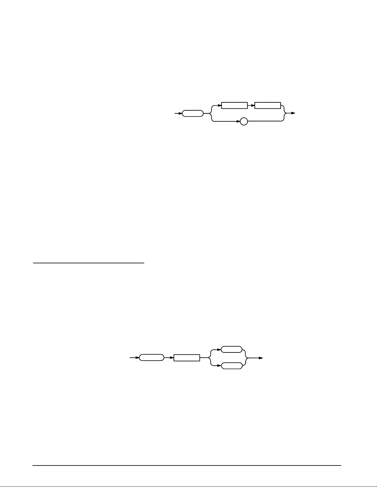
Commands
Related Commands:
Syntax:
Arguments:
Examples:
DESE, *ESE, *RST, *SRE.
*PSC <NRf>
*PSC?
<Space>
*PSC
?
<NRf>
<NRf> is a value in the range from --- 32767 to 32767.
<NRf> = 0 sets the power-on status clear flag to FALSE, and disables the
power-on clear and allows the OA 5000 to assert SRQ after power-on.
<NRf> ¸ 0 sets the power-on status clear flag TRUE. Sending *PSC 1
therefore enables the power-on clear and prevents any SRQ assertion after
power-on. Using an out-of-range value causes an execution error.
*PSC 0
sets the power-on status clear flag to FALSE.
*PSC?
might return the value 1, showing that the power-on status clear flag is
set to TRUE.
RECall (No Query Form)
Related Commands:
Syntax:
The RECall command sets the attenuation of the instrument to either stored
value1or2.
STORe
RECall {1 | 2}
1
RECall
<Space>
2
3 --- 2 8
Programming
Page 75

REFerence
Commands
This command reads and sets the reference used when displaying the
attenuation in the ATT--- REF mode. The units for command mode and
responses is dB. Values smaller than 0.01 dB are rounded to the nearest
one-hundredth dB. The REF value may not exceed ±99.99. The combination of the REF value and the ATTen value may not exceed ±99.99. For
example, if the ATTen value is set to 30 dB and the REF value is set to
--- 70 dB, the resultant ATT ---REF value would be 100 dB, and an execution
error event would result. The factory default for REF is 0.00 (dB).
Related Commands:
Syntax:
Arguments:
Examples:
*RST (No Query Form)
N/A
REFerence <NRf>
REFerence?
<Space>
REFerence
<NRf>
?
<NRf> is a number that cannot exceed ±99.99.
REF 45.00
sets the REFerence value to 45.00 dB.
REF?
would return the string ”:REF 45.00”.
The *RST (Reset) command returns the OA 5000 to a known set of instrument settings.
Related Commands:
Syntax:
OA 5000 Series User Manual
NOTE
The *RST command can take 5 to 10 seconds to complete depending on attenuation settings.
*PSC, FACTory.
*RST
*RST
3 --- 2 9
Page 76
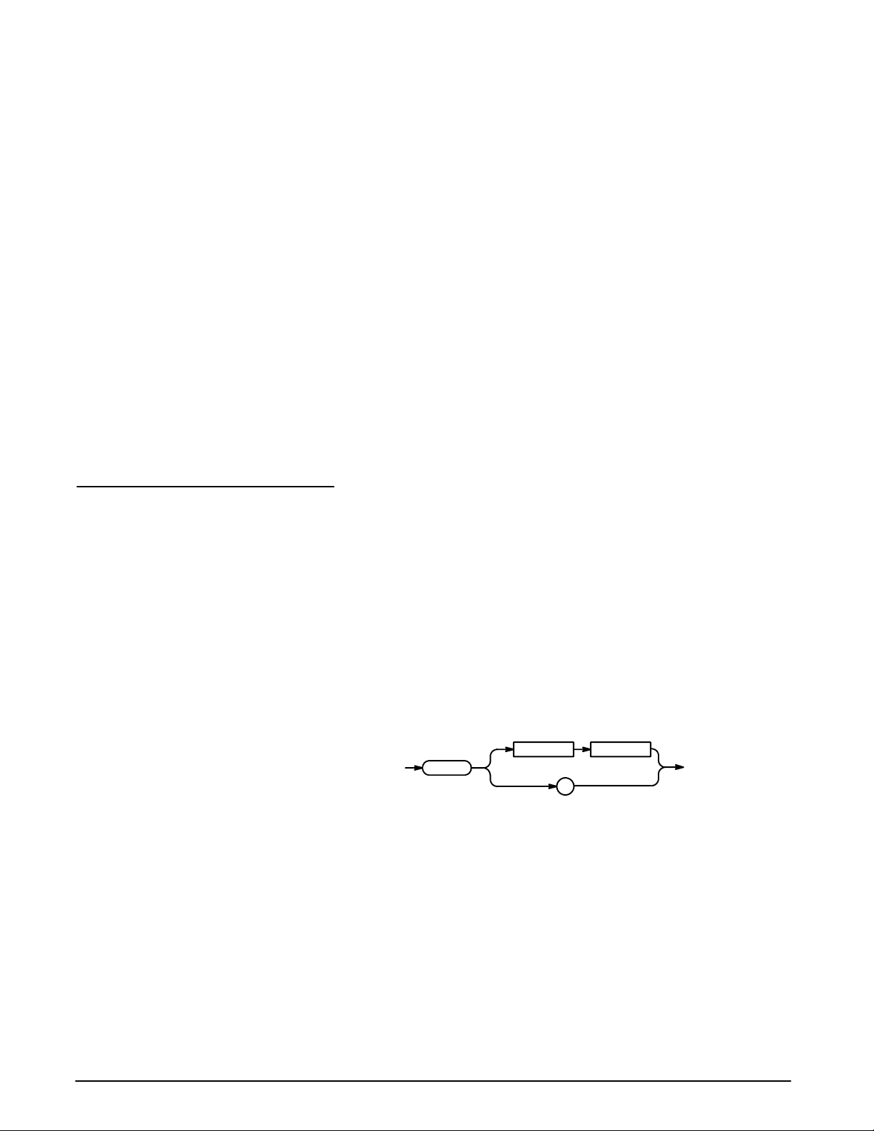
Commands
*RST does the following:
H Puts the OA 5000 into the Operation Complete Command Idle State.
H Puts the OA 5000 into the Operation Complete Query Idle State.
H Returns the instrument settings to those listed on page 3 --- 24.
The *RST command does not alter the following:
H The state of the IEEE Std 488.1 interface.
H The selected IEEE Std 488.1 address of the OA 5000.
H Calibration data that affects device specifications.
H The Output Queue.
H The Standard Status Register Enable setting.
H The Standard Event Status Enable setting.
H The Power-on status clear flag setting.
H HEADer and VERBose settings.
*SRE
Related Commands:
Syntax:
Arguments:
The *SRE (Service Request Enable) command sets and queries the bits in
the Service Request Enable Register (SRER). For a complete discussion of
the use of these registers, see page 3 --- 35.
ALLev?, *CLS, DESE, *ESE, *ESR, EVENT?, EVMSG?, EVQty?, *PSC,
*STB.
*SRE <NRf>
*SRE?
<Space> <NRf>
*SRE
?
<NRf> is a value in the range from 0 to 255. The binary bits of the SRER are
set according to this value. Using an out-of-range value causes an execution
error.
The power-on default for SRER is 0 if *PSC is 1. If *PSC is 0, the SRER
maintains its value through a power cycle.
3 --- 3 0
Programming
Page 77
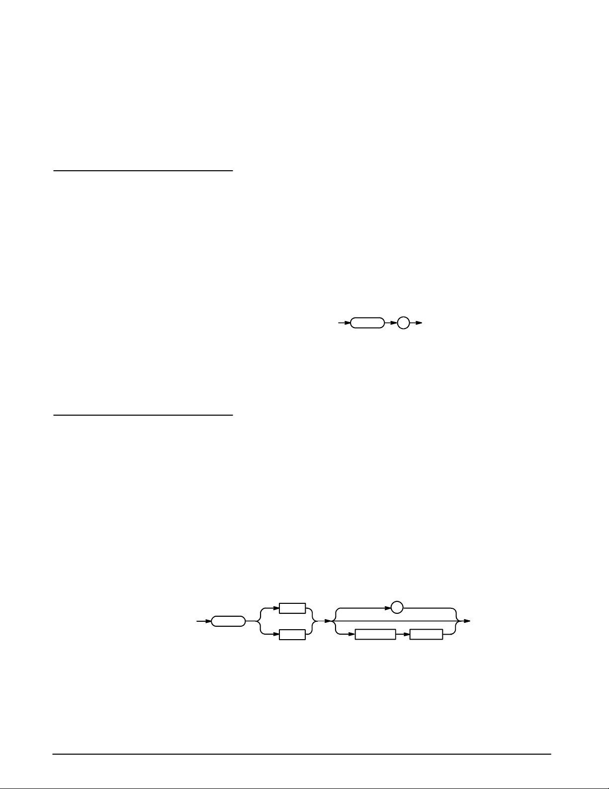
Commands
Examples:
*STB? (Query Only)
Related Commands:
Syntax:
Examples:
*SRE 48
sets the bits in the SRER to 00110000 binary.
*SRE?
might return a value of 32, showing that the bits in the SRER have the
binary value 00100000.
The *STB? (Read Status Byte) query returns the Status Byte Register (SBR)
using the Master Summary Status (MSS) bit. For a complete discussion of
the use of these registers, see page 3 --- 35.
ALLev?, *CLS, DESE, *ESE, *ESR, EVENT?, EVMSG?, EVQty?, *SRE.
*STB?
*STB ?
*STB?
might return the value 96, showing that the STB contains the binary
value 01100000.
STORe (Store Attenuation)
The STORe command sets or reads the value of stored positions 1 or 2.
Using the command form (for example, STOR1) without a value specified
stores the current attenuation in the specified location.
Related Commands:
Syntax:
RECall
STORe{1|2}?
STORe{1|2}
STORe{1|2} <NRf>
STORe
1
2
?
<NRf><Space>
OA 5000 Series User Manual
3 --- 3 1
Page 78

Commands
Arguments:
Examples:
*TST? (Query Only)
<NRf> specifies the attenuation value to be stored. The range for the attenuation value is 0 ≤ <NRf> ≤ 60.00. All attenuation values associated with the
STORe command and query forms are in absolute dB and never include the
REFERENCE value, even if the front panel display shows that the OA 5000 is
set to ATT-REF mode.
STORE1?
returns the attenuation value stored in register 1, in the form:.
:STORE1 <NRf>
STORE1 20.00
sets the attenuation value in stored register 1 to 20.00 dB.
STORE2
stores the current attenuation value in stored register 2.
The *TST? (Self-Test) query runs the OA 5000 internal self-test and reports
the results. The self-test does not require operator interaction and does not
create bus conditions that violate IEEE Std 488.1/488.2 standards. When
complete, the OA 5000 returns to the state it was in just prior to the self-test.
The test response is a value <NR1> as described in Table 3-7.
Syntax:
*TST?
*TST ?
NOTE
The *TST? query can take 5 seconds or more to respond.
Table 3-7: Results from *TST?
<NR1>
0 Test completed with no errors detected
101, 102 ROM checksum error
104 Non-volatile RAM is bad
115 System timer is bad
401 Calibration EEPROM is bad
410, 411 Calibration needed
Meaning
3 --- 3 2
Programming
Page 79
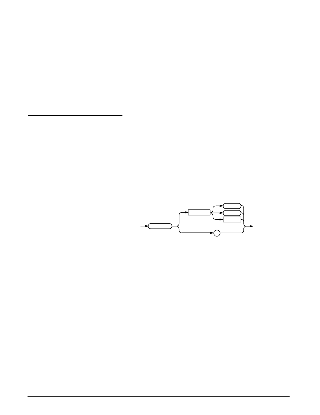
Commands
NOTE
If an error is detected, *TST? stops and returns an error code and
does not complete any remaining tests. It also places a device
dependent event in the event queue.
VERBOSE
Related Commands:
Examples:
Syntax:
*TST?
might return the value 115, indicating that the system timer is not work-
ing correctly.
The VERBOSE command sets and queries the Verbose Header State that
controls the length of headers on query responses. This command does not
affect IEEE Std 488.2 Common Commands (those starting with an asterisk).
HEADER, *LRN?.
VERBOSE { ON | OFF | <NRf> }
VERBOSE?
ON
<Space>
VERBOSE
OFF
<NRf>
?
Arguments:
Examples:
OA 5000 Series User Manual
ON or <NRf> ¸ 0 sets the Verbose Header State TRUE, which returns
full-length headers for applicable setting queries.
OFF or <NRf> = 0 sets the Verbose Header State FALSE, which returns
minimum-length headers for applicable setting queries.
VERBOSE ON
sets the Verbose Header State TRUE.
VERBOSE?
might return the value 1, showing that the Verbose Header State is
TRUE.
3 --- 3 3
Page 80

Commands
*WAI (No Query Form)
The *WAI (Wait) command prevents the OA 5000 from executing further
commands or queries until all pending operations finish.
Related Commands:
WAVelength
Related Commands:
Syntax:
Syntax:
*OPC, AD Justing?.
*WAI
*WAI
This commands set or queries the wavelength used by the instrument when
determining the equivalent attenuator positioning for a given attenuation.
N/A
WAVelength <NRf>
WAVelength?
<Space>
WAVelength
<NRf>
?
Arguments:
Examples:
The valid range for the wavelength argument is 600 nm to 1700 nm. Default
units are always in nanometers with N (for nano or 1E --- 09) and U (for micro
or 1E --- 06) accepted as multipliers; M (for meters) is also an acceptable term
(see examples below).
WAV?
returns the value of wavelength to which the OA 5000 is set. An example
response is:
:WAVELENGTH 1300
WAV 1300
sets the wavelength to 1300 nm.
WAV 1300NM
sets the wavelength to 1300 nm.
WAV 1.3UM
sets the wavelength to 1300 nm.
WAV 1.3E-09M
sets the wavelength to 1300 nm.
3 --- 3 4
Programming
Page 81

Status and Events
The OA 5000 provides a status and event reporting system for the GPIB
interfaces. This system informs you of certain significant events that occur
within the OA 5000.
The OA 5000 status handling system consists of five 8 -bit registers and two
queues. This section describes these registers and components and explains how the event handling system operates.
Registers
The registers in the event handling system fall into two functional groups:
H The Standard Event Status Register (SESR) and the Status Byte Regis-
ter (SBR) contain information about the status of the OA 5000. These
registers are therefore called the Status Registers.
H The Device Event Status Enable Register (DESER), the Event Status
Enable Register (ESER), and the Service Request Enable Register
(SRER) determine whether selected types of events are reported to the
Status Registers and the Event Queue. These three registers are called
the Enable Registers.
Status Registers
The Standard Event Status Register (SESR) and the Status Byte Register
(SBR) record certain types of events that may occur while the OA 5000 is in
use. These registers are defined by IEEE Std 488.2-1987. Refer also to
Figure 3-6 and Table 3-8.
Each bit in a Status Register records a particular type of event, such as an
execution error or service request. When an event of a given type occurs,
the bit that represents that type of event is set to a value of one. (You can
disable bits so that they ignore events and remain at zero; see the Enable
Registers section on page 3---37.) Reading the status registers tells you
what types of events have occurred.
The Standard Event Status Register (SESR) — The SESR, shown in
Figure 3-6, records eight types of events that can occur within the OA 5000.
Use the *ESR? query to read the SESR register. Reading the register clears
the bits of the register so that the register can accumulate information about
new events.
76543210
PON URQ CME EXE DDE QYE RQC OPC
Figure 3-6: The Standard Event Status Register (SESR)
OA 5000 Series User Manual 3 --- 3 5
Page 82

Status and Events
Table 3-8: SESR Bit Functions
Bit
Function
7 (MSB) PON (Power On). Shows that the OA 5000 was powered on.
6 URQ (User Request). Shows that the Remote button was
pressed.
5 CME (Command Error). Shows that an error occurred while
the OA 5000 was parsing a command or query. Command
error messages are listed in Table 3-11 on page 3 ---41.
4 EXE (Execution Error). Shows that an error occurred while
the OA 5000 was executing a command or query. Execution
error messages are listed in Table 3-12 on page 3 ---42.
3 DDE (Device Error). Shows that a device error occurred. De-
vice error messages are listed in Table 3-13 on page 3 ---43.
2 QYE (Query Error). Shows that either an attempt was made
to read the Output Queue when no data was present or
pending, or that data in the Output Queue was lost.
1 RQC (Request Control). Not used.
0(LSB) OPC (Operation Complete). Shows that the operation is com-
plete. This bit is set by the *OPC command.
The Status Byte Register (SBR) — shown in Figure 3-7, records wheth-
er output is available in the Output Queue, w hether the OA 5000 requests
service, and whether the SESR has recorded any events.
Use a Serial Poll or the *STB? query to read the contents of the SBR. Refer
to Table 3-9. The bits in the SBR are set and cleared depending on the
contents of the SESR, the Event Status Enable Register (ESER), and the
Output Queue. (When you use a Serial Poll to obtain the SBR, bit 6 is the
RQS bit. When you use the *STB? query to obtain the SBR, bit 6 is the MSS
bit.)
6
RQS
7
—
Figure 3-7: The Status Byte Register (SBR)
543210
ESBMAV————
6
MSS
3 --- 3 6
Programming
Page 83

Table 3-9: SBR Bit Functions
Status and Events
Bit
Function
7 (MSB) Not used (always 0).
6 RQS (Request Service ), obtained from a serial poll. Shows
that the OA 5000 requests service from the GPIB controller.
6 MSS (Master Status Summary), obtained from *STB? query.
Summarizes the ESB and MAV bits in the SBR.
5 ESB (Event Status Bit). Shows that status is enabled and
present in the SESR.
4 MAV (Message Available). Shows that output is available in
the Output Queue.
3 --- 0 Not used (always 0).
Enable Registers
The DESER, ESER, and SRER allow you to select which events are reported
to the Status Registers and the Event Queue. Each Enable Register acts as
a filter to a Status Register (the DESER also acts as a filter to the Event
Queue), and can prevent information from being recorded in the register or
queue.
Each bit in an Enable Register corresponds to a bit in the Status Register it
controls. In order for an event to be reported to its bit in the Status Register,
the corresponding bit in the Enable Register must be set to one. If the bit in
the Enable Register is set to zero, the event is not recorded.
The bits in the Enable Registers are set using various commands. The
Enable Registers and the commands used to set them are described below.
The Device Event Status Enable Register (DESER) — is shown in
Figure 3-8. This register controls which types of events are reported to the
SESR and the Event Queue. The bits in the DESER correspond to those in
the SESR, as described earlier.
Use the DESE command to enable and disable the bits in the DESER. Use
the DESE? query to read the DESER.
76543210
PON URQ CME EXE DDE QYE RQC OPC
Figure 3-8: The Device Event Status Enable Register (DESER)
OA 5000 Series User Manual
3 --- 3 7
Page 84

Status and Events
The Event Status Enable Register (ESER) — isshowninFigure3-9.It
controls which types of events are summarized by the Event Status Bit
(ESB) in the SBR.
Use the *ESE command to set the bits in the ESER, and use the *ESE?
query to read it.
76543210
PON URQ CME EXE DDE QYE RQC OPC
Figure 3-9: The Event Status Enable Register (ESER)
The Service Request Enable Register (SRER) — is shown in Figure
3-10. It controls which bits in the SBR generate a Service Request and are
summarized by the Master Status Summary (MSS) bit.
Use the *SRE command to set the SRER. Use the SRE? query to read it.
The RQS bit remains set to one until either the Status Byte Register is read
with a Serial Poll or the MSS bit changes back to a zero.
76543210
——ESB MAV ————
Figure 3-10: The Service Request Enable Register (SRER)
The Enable Registers and the *PSC Command
The *PSC command controls the contents of the Enable Registers at poweron. Sending *PSC 1 sets the Enable Registers at power on as follows:
H DESER 255 (equivalent to a DESe 255 command)
H ESER 0 (equivalent to an *ESE 0 command)
H SRER 0 (equivalent to an *SRE command)
Sending *PSC 0 lets the Enable Registers maintain their values in nonvolatile memory through a power cycle.
NOTE
T o enable the PON (Power On) event to generate a Service Request, send *PSC 0, use the DESe and *ESE commands to enable
PON in the DESER and ESER, and use the *SRE command to
enable bit 5 in the SRER. Subsequent power-on cycles will generate a Service Request.
3 --- 3 8
Programming
Page 85

Status and Events
Queues
The OA 5000 status and event reporting system contains two queues: the
Output Queue and the Event Queue.
The Output Queue
The Output Queue stores up to 8000 bytes of a query response while it is
waiting to be output. The Output Queue is emptied each time a new command or query message is received, so that any query response must be
read before the next command or query is sent, or responses to earlier
queries will be lost, and an error may result.
The Event Queue
The Event Queue stores detailed information on up to 32 events. If more
than 32 events stack up in the Event Queue, the 32nd event is replaced by
event code 350, “Too many events.”
Read the Event Queue with either the EVENT? query (which returns only the
event number) or with the EV MSG? query (w hich returns the event number
and a text description of the event). Reading an event removes it from the
queue.
Before reading an event from the Event Queue, you must use the *ESR?
query to read the summary of that event from the SESR. This makes the
events summarized by the *ESR? read available to the EVENT? and
EVMSG? queries, and empties the SESR.
Event Handling Sequence
Reading the SESR erases any events that were summarized by a previous
*ESR? read but not read from the Event Queue. Events that follow an *ESR?
read are put in the Event Queue but are not available until *ESR? is used
again.
Figure 3-11, on page 3 --- 40, shows how to use the status and event handling system. In the explanation that follows, numbers in parentheses refer to
numbers in Figure 3-11.
When an event occurs, a signal is sent to the DESER (1). If that type of
event is enabled in the DESER (that is, if the bit for that event type is set to
1), the appropriate bit in the SESR is set to one and the event is recorded in
the Event Queue (2). If the corresponding bit in the ESER is also enabled
(3), then the ESB bit in the SBR is set to one (4).
When output is sent to the Output Queue, the MAV bit in the SBR is set to
one (5).
When a bit in the SBR is set to one and the corresponding bit in the SRER is
enabled (6), the MSS bit in the SBR is set to one and a service request is
generated (7).
OA 5000 Series User Manual
3 --- 3 9
Page 86

Status and Events
1
Device Event Status Enable Register
(DESER)
Standard Event Status Register
(SESR)
Event Status Enable Register
(ESER)
Status Byte Register
(SBR)
Service Request Enable Register
(SRER)
76543210
PON URQ CME EXE DDE QYE RQC OPC
2
76543210
PON URQ CME EXE DDE QYE RQC OPC
3
76543210
PON URQ CME EXE DDE QYE RQC OPC
4
6
RQS
7
—
7
76543210
——ESB MAV ————
543210
ESB MAV ————
6
MSS
6
5
Event
Event
Event
Byte
Byte
Byte
Event
Queue
Output
Queue
Conflicts
3 --- 4 0
Figure 3-11: Status and Event Handling Process
Whenever a command is issued that results in a conflict, an event is generated on the EXE bit (bit 4).
You can avoid generating this event if you concatenate commands so that
the conflict is resolved when the command is completed. For example, when
setting the attenuator in DBR mode, always make sure that the REF command precedes the ATT:DBR command or an execution warning may result.
Programming
Page 87

Status and Events
Messages
Tables 3-10 through 3-15 list all the programming interface messages the
OA 5000 generates in response to commands and queries.
For most messages, a secondary message from the OA 5000 gives more
detail about the cause of the error or the meaning of the message. This
message is part of the message string, and is separated from the main
message by a semicolon.
Each message is the result of an event. Each type of event sets a specific bit
in the SESR, and is controlled by the equivalent bit in the DESER. Thus,
each message is associated with a specific SESR bit. In the message tables
that follow, the associated SESR bit is specified in the table title, with exceptions noted with the error message text.
Table 3-10 shows the messages when the system has no events or status to
report. These have no associated SESR bit.
Table 3-10: No Event Messages
Code
0 No events to report --- queue empty
1 No events to report --- new events pending *ESR?
Table 3-11 shows the error messages generated by improper command
syntax. Check that the command is properly formed and that it follows the
rules in the Command Syntax chapter starting on page 3--- 5.
Message
Table 3-11: Command Error Messages — CME Bit 5
Code
100 Command error
101 Invalid character
102 Syntax error
103 Invalid message or unit separator
104 Data type error
105 GET not allowed
106 Invalid program data separator
108 Parameter not allowed
109 Missing parameter
110 Command header error
111 Header separator error
112 Program mnemonic too long
Message
OA 5000 Series User Manual
3 --- 4 1
Page 88

Status and Events
Table 3-11: Command Error Messages — CME Bit 5 (Cont.)
Code Message
113 Undefined header
118 Query not allowed
120 Numeric data error
121 Invalid character in number
123 Numeric overflow
124 Too many digits
128 Numeric data not allowed
130 Suffix error
131 Invalid suffix
134 Suffix too long
138 Suffix not allowed
140 Character data error
141 Invalid character data
144 Character data too long
148 Character data not allowed
150 String data error
151 Invalid string data
158 String data not allowed
160 Block data error
161 Invalid block data
168 Block data not allowed
Table 3-12 lists the execution errors that are detected during execution of a
command. In these error messages, you should read “macro” as “alias.”
Table 3-12: Execution Error Messages — EXE Bit 4
Code
Message
3 --- 4 2
200 Execution error
220 Parameter error
221 Settings in conflict
Programming
Page 89

Status and Events
Table 3-12: Execution Error Messages — EXE Bit 4 (Cont.)
Code Message
222 Data out of range
223 To o m u c h d a t a
Table 3-13 lists the device errors that can occur during operation of the
OA 5000. These errors may indicate that the OA 5000 needs repair.
Table 3-13: Device Error Messages — DDE Bit 3
Code
Message
300 Internal error
310 System error
313 Calibration memory lost
315 Configuration memory lost
350 Too many events (Does not set DDE bit)
Table 3-14 lists the system event messages. These messages are generated
whenever certain system conditions occur.
Table 3-14: System Event Messages — QYE Bit 2
Code
Message
401 Power on --- PON Bit 7
402 Operation complete --- OPC Bit 0
403 User request --- URQ Bit 6
410 Query INTERRUPTED
OA 5000 Series User Manual
420 Query UNTERMINATED
430 Query DEADLOCKED
440 Query UNTERMINATED after indefinite response
Table 3-15 lists warning messages that do not interrupt the flow of command
execution. These notify you that you might get unexpected results.
Table 3-15: Execution Warning Messages — EXE Bit 4
Code
Message
500 Execution warning
3 --- 4 3
Page 90

Status and Events
3 --- 4 4
Programming
Page 91

Appendices
Page 92

Page 93

Appendix A: Accessories
Some accessories are included with the OA 5000. If you wish to purchase
optional accessories, or purchase additional standard accessories, see a
Tektronix products catalog or contact your local Tektronix field representa tive.
Standard Accessories
Optional Accessories
H This manual, the OA 5000 Optical Attenuator User Manual (Tektronix part
number 070-7612-03).
H The TM 5003 Power Module, Tektroninx part number 620-0057-00
H Two universal optical input and output connector kits, Tektronix part
number 020-1885-00.
H Two blank plug-in panels, Tektronix part number 016-0195-05
The optional accessories appropriate for your instrument depend on which
OA 5000 Optical Attenuator you purchased.
Optical Cables, Single Mode, 2 meter, 8/125 micron
H FC/PC to Diamond 2.5, Tektronix part number 174-1497-00.
H FC/PC to Diamond 3.5, Tektronix part number 174-1385-00.
H FC/PC to ST, Tektronix part number 174-1386-00.
H FC/PC to FC/PC, Tektronix part number 174-1387-00.
H FC/PC to Biconic, Tektronix part number 174-1388-00.
Optical Cables, Multimode, 2 meter, 62.5/140 micron
H FC/PC to Biconic, Tektronix part number 174-2323-00.
H FC/PC to SMA906, Tektronix part number 174-2324-00.
H FC/PC to FC/PC, Tektronix part number 174-2322-00.
Optical Cables, Multimode, 2 meter, 100/140 micron
(Note: at the time of publication, the 100 m cables listed below did not
utilize physical contact connectors)
H FC to SMA, Tektronix part number 174-0878-00.
H ST to SMA, Tektronix part number 174-0876-00.
H Diamond 2.5 to SMA, Tektronix part number 174-1303-00.
OA 5000 Series User Manual A --- 1
Page 94

Appendix A: Accessories
A --- 2
Appendices
Page 95

Appendix B: S pecifications
The performance characteristics described in this appendix (Tables A-1
through A-3) are valid under the following conditions:
H The instrument must have been calibrated at an ambient temperature
between +20_ C and +30_ C.
H The instrument must have had a warm-up period of at least 20 minutes.
H All optical connections to the instrument are made using physical con-
tact connectors. Tektronix offers limited selection of fiber optic jumper
cables which utilize physical contact on the connector ends (for exam-
ple: Tektronix part number 174-1387-00, see Appendix A).
H Both input and output connectors have been cleaned as described on
page A--- 15.
Table A-1: Optical Characteristics
Characteristic
Wavelength Range OA 5002 1100 --- 1600 nm
Input
OA 5002
OA 5012
OA 5022
OA 5032
Insertion Loss
750 --- 1100 nm
1100--- 1350 nm
1350--- 1600 nm
Return Loss
OA 5002
OA 5012/5022/5032
Attenuation Range
OA 5002
1100 --- 1350 nm
1350--- 1600 nm
OA 5012/22/32
750--- 1350 nm
1350--- 1600 nm
Specification
OA 5012/22/32 750 --- 1600 nm
Single Mode Fiber
50 m Multimode Fiber
62.5 m Multimode Fiber
100 m Multimode Fiber
≤ 4.0 dB (OA 5012/22/32 only)
≤ 2.0 dB
≤ 2.5 dB
≤ --- 4 5 dB
≤ --- 2 5 dB
≥ 60 dB (calibrated, 0.01 dB step size)
≥ 50 dB (calibrated, 0.01 dB step size)
≥ 60 dB (calibrated, 0.01 dB step size)
≥ 50 dB (calibrated, 0.01 dB step size)
Maximum Attenuation
OA 5002/5012/5022
OA 5032
Repeatability ±0.05dB
OA 5000 Series User Manual A --- 3
≥ 100 dB (shutter activated)
≥ 90 dB (shutter activated)
Page 96

Appendix B: Specifications
Table A-1: Optical Characteristics (Cont.)
Characteristic Specification
Linearity ± 0.1 dB max (typically ± 0.05 dB)
Accuracy
OA 5002
1310 ± 20 nm
1550 ± 20 nm
≤ ±0.15dB(typically≤ ±0.05dB)
≤ ±0.15dB(0to40dB)(typically≤±0.05dB)
≤ ±0.20dB(≥40 dB)
All other wavelengths
Typically ≤ ±0.25 dB
OA 5012/5022/5032
850 ± 20 nm
1310 ± 20 nm
1550 ± 20 nm
All other wavelengths
≤ ±0.20dB(typically≤ ±0.05dB)
≤ ±0.20dB(typically≤ ±0.05dB)
≤ ±0.20dB(typically≤ ±0.05dB)
Typically ≤ ±0.25dB
Table A-2: Mechanical Characteristics
Characteristic
Specification
Net Weight 1.3 kg (2.86 lb.)
External Dimensions
Height
Width
Length
14.0 cm (5.5 in.)
23.4 cm (9.2 in.)
44.4 cm (17.4 in.)
A --- 4
Characteristic
Temperature
Operating
Nonoperating
(storage)
Altitude
Operating
Nonoperating
Table A-3: Environmental Performance
Specification
0_ C to +50_ C (32_ Fto122_ F)
--- 4 0 _ C to +70_ C ( --- 4 0 _ Fto160_ F)
(Meets MIL--- T --- 28800D, class 5.)
4.6 km (15,000 ft.)
15 km (50,000 feet)
(Exceeds MIL--- T --- 28800D, class 5.)
Appendices
Page 97

Table A-3: Environmental Performance (cont.)
Characteristic Specification
Humidity
Operating and
Nonoperating
95% RH: 11_ Cto30_ C (52_ Fto86_ F)
75% RH: 11_ Cto40_ C (52_ Fto104_ F)
45% RH: 11_ Cto50_ C (52_ Fto122_ F)
(Exceeds MIL--- T --- 28800D, Class 5, noncondensing)
Appendix B: Specifications
Vibration
1
Requires retainer clip
2
Refer to TM5000 Power Module specifications
3
Without power module
Shock
1
1
0.38 mm (0.015 in.) p-p, 5 Hz to 55 Hz, 75 minutes. Meets MIL--- T--- 28800D, Class 5, when
installed in qualified power modules
2
.
30 g’s, (1/2 sine), 11 ms duration, 3 shocks in
each direction along 3 major axes, 18 total
shocks. Meets MIL--- T--- 28800D, Class 5, when
installed in qualified power modules.
Bench Handling
3
12 drops from 45_, 4 in. or equilibrium, whichever occurs first. Meets MIL --- T --- 28800D, Class 5,
when installed in qualified power modules
2
,and
IEC 348 (Electronic measuring apparatus).
Packaged Product Vibration and Shock
1
The packaged product qualifies under the National Safe Transit Association’s Preshipment
Test Procedures, Project 1A--- B---1 and
1 A --- B --- 2 .
Electrical Discharge 8 kV maximum discharge applied to operating
instrument from an ESD source per IEC 801 --- 2
(150 Ω/150 pF)
OA 5000 Series User Manual
1
Requires retainer clip
2
Refer to TM5000 Power Module specifications
3
Without power module
A --- 5
Page 98

Appendix B: Specifications
A --- 6
Appendices
Page 99

Appendix C: Interface Specifications
This appendix describes details of the remote interface of the Optical
Attenuator, that is, the GPIB. Normally, you will not need this information to
use the OA 5000, but the information is useful when connecting to controllers of unusual configuration.
This appendix also contains general information that pertains to programming with both interfaces. This information includes a chart of the ASCII
character set and a list of reserved words.
Interface Messages
Table A-4 shows the standard interface messages that are supported by the
OA 5000.
Table A-4: OA 5000 Standard Interface Messages
Message
DCL Ye s
GET No
GTL Yes
LLO Yes
PPC No
PPD No
PPE No
PPU No
SDC Yes
SPD Ye s
SPE Yes
GPIB
UNL Ye s
UNT Yes
Listen Addresses Yes
Talk Addresses Yes
OA 5000 Series User Manual A --- 7
Page 100

Appendix C: Interface Specifications
Character Set (ASCII Chart)
0 1 2 3 4 5 6 7
0
1
2
3
4
5
6
NUL
SOH
STX
ETX
EOT
ENQ
ACK
Table A-5 shows the character set used for all messages to and from the
OA 5000. This is identical to standard ASCII.
Table A-5: The ASCII Character Set
DLE
0
DC1
1
DC2
2
DC3
3
DC4
4
NAK
5
SYN
6
16
17
18
19
20
21
22
space
!
”
#
$
%
&
32
48
1
0
33
49
2
34
50
3
35
51
4
36
52
5
37
53
6
38
54
@
A
B
C
D
E
F
64
80
Q
P
65
81
R
66
82
S
67
83
T
68
84
U
69
85
V
70
86
b
c
d
e
‘
96
a
97
p
112
q
113
r
98
114
s
99
115
t
100
116
u
101
f
102
117
v
118
7
8
9
A
B
C
D
E
F
BEL
BS
HT
LF
VT
FF
CR
SO
SI
ETB
7
23
CAN
8
24
EM
9
25
SUB
10
26
ESC
11
27
FS
12
28
GS
13
29
RS
14
30
US
15
31
’
(
)
*
+
,
---
.
/
39
55
8
7
40
56
9
41
57
:
42
58
;
43
59
<
44
60
=
45
61
>
46
62
?
47
63
G
H
J
K
L
M
N
O
71
87
X
W
72
I
73
88
Y
89
Z
74
90
[
75
91
\
76
92
]
77
93
^
78
94
_
79
95
g
h
k
m
n
o
103
119
x
w
104
i
105
j
106
120
y
121
z
122
{
107
l
108
123
|
124
}
109
125
~
110
126
rubout
111
127
A --- 8
Appendices
 Loading...