

Page 1

xx
NetTek®YBT250
Field Transmitter & Interference Tester
ZZZ
Quick Start User Manual
Revision A
www.tektronix.com
071-2409-01
Page 2

Copyright © Tektronix. All rights reserved. Licensed software products are owned by Tektronix or its subsidiaries or suppliers, and are protected by
national copyright laws and international treaty provisions.
Tektronix products are covered by U.S. and foreign patents, issued and pending. Information in this publication supersedes that in all previously
published material. Specifications and price change priv ileges reserved.
TEKTRONIX and TEK are registered trademarks of Tektronix, Inc.
NetTek is a registered trademark of Tektronix, Inc.
Contacting Tektronix
Tektronix, Inc.
14200 SW Karl Braun Drive
P.O . B o x 5 0 0
Beaverton, OR 97077
USA
For product information, sales, service, and technical support:
In North Am erica, call 1-800-833-9200.
Worldwide, visit www.tektronix.com to find contacts in your area.
Page 3

Warranty 2
Tektronix warrants that this product will be free from defects in materials and workman ship for a period of one (1) year from the date of shipment. If
any such product proves defective during this warranty period, Tektronix, at its option, either will repair the defective product without charge for parts
and labor, or will provide a replacement in exchange for the defective product. Parts, modules and rep lacement products used by Tektronix for
warranty work may be new or reconditioned to like new performance. All replaced parts, modules and products become the property of Tektronix.
In order to obtain servic e under this warranty, Customer must notify Tektronix of the defect before the expiration of the warranty period and make
suitable arrangements for the performance o f service. Customer shall be responsible for packaging and shipping the defective product to the s ervice
center designated by Tektronix, with shipping charges prepaid. Tektronix shall pay for the return of the product to Customer if the shipment is to a
location within the country in which the Tektronix service center is located. Customer shall be responsible for paying all shipping charges, duties,
taxes, and any other charges for products returned to any other locations.
This warra nty shall not apply to any defect, failure or damage caused by improper use or improper or inadequate maintenance and care. Tektronix
shall not be obligated to furnish service under this warranty a) to repair damage resulting from attempts by personnel other than Tektronix
representatives to install, repair or service the product; b) to repair damage resulting from improper use or connection to incompatible equipment; c) to
repair any damage or malfunction caused by the use of non-Tektronix supplies; or d) to service a product that has been modified or integrated with
other products when the effect of such modification or integration increases the time or difficulty of servicing the product.
THIS WARRANTY IS GIVEN BY TEKTRONIX WIT H RESPECT TO THE PRODUCT IN LIEU OF ANY OTHER WARRANTIES, EXPRESS OR
IMPLIED. TEKTRONIX AND ITS VENDORS DISCLAIM ANY IMPLIED WARRANTIES OF MERCHANTABILITY OR FITNESS FOR A PARTICULAR
PURPOSE. TEKTRONIX’ RESPONSIBILITY TO REPAIR OR REPLACE DEFECTIVE PRODUCTS IS THE SOLE AND EXCLUSIVE REMEDY
PROVIDED TO THE CUSTOMER FOR BREACH OF THIS WARRANTY. TEKTRONIX AND ITS VENDORS WILL NOT BE LIABLE FOR ANY
INDIRECT, SPECIAL, INCIDENTAL, OR CONSEQUENTIAL DAMAGES IRRESPECTIVE OF WHETHER TEKTRONIX OR THE VENDOR HAS
ADVANCE NOTICE OF THE POSSIBILITY OF SUCH DAMAGES.
Page 4

Page 5

Table of Contents
General Safe ty Summary .. . ............................................................................................................... iii
Environmental Considerations ............................................................................................................. vi
Preface..................................................................................................................................... vii
Key Features......................................................................................................................... vii
Documentation....................................................................................................................... viii
Software Upgrades ................................................................................................................... ix
Conventions Used in This Manual.................................................................................................... ix
Preventing Personal Injury from Lightning ............................................................................................ x
Installation .................................................................................................................................. 1
YBT250 Standard Accessories ....................................................................................................... 1
Operating Considerations ............................................................................................................ 2
Connecting the AC Adapter . ......................................................................................................... 4
Charging the Batteries................................................................................................................ 5
Powering On and Off the Instrument, and Functional Verification................................................................... 6
Touch Screen Concepts .............................................................................................................. 7
Calibrate the Touch Screen........................................................................................................... 8
Starting the YBT250 Application..................................................................................................... 10
Setting Display Colors ............................................................................................................... 11
Enabling Signal Standards .......................................................................................................... 12
Table of Contents
NetTek
®
YBT250 Quick Start User Manual i
Page 6

Table of Contents
Getting Acquainted with Your Instrument ................................................................................................. 15
Operating Basics .......................................................................................................................... 27
Instrument Elements................................................................................................................. 15
PowerOn/Standby and Status Panel ............................................................................................... 16
Input/Output Co nnectors (NetTek Y400 Platform) . ................................................................................. 17
NetTek YBT 250 Module Signal Connectors. ........................................................................................ 18
Microsoft WindowsCE Elements . ................................................................................................... 18
The User Interface ................................................................................................................... 19
The Command Bar...................................................................................................................20
The Tuning Controls ................................................................................................................. 21
The External Signal Status Buttons ................................................................................................. 22
The Measurement Mode Buttons.................................................................................................... 23
The Parameter Entry Controls.......................................................................................................24
Getting Help.......................................................................................................................... 25
Setting Up to Take a Measurement ................................................................................................. 27
Signal Measurements................................................................................................................ 32
Spectrum Measurements............................................................................................................34
Interference Measurements ......................................................................................................... 45
Displaying Multiple Measurements..................................................................................................57
Specifications.............................................................................................................................. 59
Certifications and Compliances ..................................................................................................... 88
Index
ii NetTek
®
YBT250 Quick Start User Manual
Page 7

General Safety Summary
Review the following safety precautions to avoid injury and prevent damage to t his product or any products connected to it.
To avoid potential hazards, use this product only as specified.
Only qualified personnel should pe rform service procedures.
While using this product, you may need to access other parts of a larger system. Read the safety sections of the other component
manuals for warnings and cautions related to operating the system.
To Avoid Fire or Personal Injury
Use Proper Power Cord. Use only the power cord specified for this product and certified for the country of use.
Observe All Terminal Ratings. To avoid fire or shock hazard, observe all ratings and markings on the product. Consult the
product manual for further ratings information before making connections to the product.
The inputs are not rated for connection to mains or Category II, III, or IV circuits.
Power Disconnect. The power cord disconnects the product from the power source. Do not block the power cord; it must remain
accessible to the user at all times.
Do Not Operate Without Covers. Do not operate this product with covers or panels removed.
Do Not Operate With Suspected Failures. If you suspect that there is damage to this product, have it inspected by qualified
service personnel.
General Safety Summary
NetTek
Avoid Exposed Circuitry. Do not touch exposed connections and components when power is present.
Replace Batteries Properly. Replace batteries only with the specified type and rating.
®
YBT250 Quick Start User Manual iii
Page 8
General Safety Summary
Recharge Batteries Properly. Recharge batteries for the recommended charge cycle only.
Use Proper AC Adapter. Use only the AC adapter specified for this product.
Do Not Operate in an Explosive Atmosphere.
TermsinthisManual
These terms may appear in this manual:
WARNING. Warning statements identify conditions or practices that could result in injury or loss of life.
CAUTION. Caution sta tements identify conditions or practices that could result in damage to this product or other property.
Symbols and Terms on the Product
These terms may appear on the product:
DANGER indicates an injury hazard immediately accessible as you read the marking.
WARNING indicates an injury hazard not immediately accessible as you read the marking.
CAUTION indicates a hazard to property including the product.
iv NetTek
®
YBT250 Quick Start User Manual
Page 9

The following symbol(s) may appear on the product:
General Safety Summary
NetTek®YBT250 Quick Start User Manual v
Page 10

Environmental Considerations
Environmental Considerations
This section provides information about the environmental impact of the product.
Product End-of-Life Handling
Observe the following guidelines when recycling an instrument or component:
Equipment Recycling. Production of this equipment required the extraction and use of natural resources. The equipment may
contain substances that could b e harmful to the environment or huma n health if improp erly handled at th e product’s end of life. In
order to avoid release of such substances into the environment and to reduce the use of natural resources, we encourage you to
recycle this product in an appropriate system that will ensure that m ost of the materials are reused or recycled appropriately.
This symbol indicates that this product complies with the European Union’s requirements according to Directive
2002/96/EC on waste electrical and electronic equipment (WEEE). For information about recycling options, check
the Support/Service section of the Tektronix Web site (www.tektronix.com).
Restriction of Hazardous Substances
This product has been classified as Monitoring and Contro l equipment, and is outside the scope of the 2002/95/EC RoHS Directive.
vi NetTek
®
YBT250 Quick Start User Manual
Page 11

Preface
This manual describes the installation and basic op eration of the NetTek YBT250 Field Transmitter & Interference Tester. For
more detailed information on individual measurements, tap the underlined link text on measurement screens to open the online
help for those topics.
Key Features
The N etTek YBT250 is a rugged, multi-standard measurement and interference location tool optimized for field use. Key features
include:
Multi-standard frequency spectrum analyzer
Interference hunting functions that help find interference quickly
Spectrogram display for detection and logging of intermittent signals
Signal strength, AM/FM demodulation, and noise floor measurements
Scanners or code analyzers for GSM/GMSK/EDGE, UMTS/W-CDMA/HSDPA, cdmaOne, cdma2000, 1xEV-DO, TD-SCDMA,
and iDEN signals
Multipath signal analyzer for W-CDMA signals
User-defined channels for taking general measurements and channel scans
Preface
NetTek
®
YBT250 Quick Start User Manual vii
Page 12

Preface
Documentation
To read about Use these documents
Installation and operation (overviews) NetTek YBT250 Field Transmitter & Interference Tester Quick Start User Manual.The
Help using the application
quick start user manual contains general info rmation about how to put your instrument
into service, guides to user interface controls, and application examples.
Online H elp. The online help is context sensitive, displaying information appropriate
for the active screen or the selected help text. (See page 25, Getting Help.)
viii NetTek®YBT250 Quick Start User Manual
Page 13

Software Upgrades
Periodic software upgrades may become available. The software is operational only if you have a valid option key for the specific
application module and serial number.
To check for upgrades:
1. Go to the Tektronix Web site (www.tektronix.com).
2. Click Software Downloads on left side of the screen to link to the Software Downloads Web page.
3. Enter the product name or model number in the Search by keyword field and click Go.
4. Scroll through the list and select the appropriate link for your instrument to show more information or to download the software.
The instructions to perform the software upgrade are in the readme.txt file that is part of the software down load.
Conventions Used in This Manual
The following icons are used in this ma nual:
Preface
Sequence
Step
NetTek®YBT250 Quick Start User Manual ix
Front panel
power
Connect
power
Page 14
Preface
Preventing Personal Injury from Lightning
WARNING. To prevent perso nal injury from the effects of lightning, exercise the following precautions when using this product:
Before connecting this produ ct to any source
Check your local weather forecast for the possibility of thunderstorms or lightn ing.
If weather conditions could allow thunderstorms or lightning to develop, be sure to visually check t he sky and weather
conditions in your area frequently.
If you c an hear thunder or if you see lightning, do not connect this product to any source which m ay be exposed to the
effects of lightning.
Use your own good judgement and common sense. You must protect yourself from the effects of lightning.
You must a ssume that hazardous voltages will be present on exposed surfaces of this product if it is connected to a source
exposed to lightning. The insulation of this product will not protect you from these hazardous voltages.
x NetTek
®
YBT250 Quick Start User Manual
Page 15

Do not connect this product to any source which might be subject to the effects of lightning
If thunderstorms or lightning are in your vicinity:
When weather conditions that could lead to lightning activity exist in your area, you could be at risk of a lightning strike
before the cloud is close enough for you to hear thunder or see lightning.
When lightning strikes a structure or facility, current travels through rebar, concrete, pipes, cables, vent stacks, and electrical
system.
Lightning can induce electric and magnetic fields into structures and portions of wiring. The length of a conductor affected by
the magnetic field of a lightning strike may exceed two miles.
Be alert and aware of the effects of lightning
When lightning strikes a conductor, which in turn introduces the current into an area some distance from the ground strike point,
equipment can be damaged and personnel injured if they become an indirect path in the completion of the ground circuit.
Conductors such as the braided shields of cables or unshielded wires will have significant transient currents flowinginthem
in regions exposed to the electric field effect of lightning.
Induced voltages may cause breakdown of insulation in wiring at connectors and in electrical components or brea k down of air.
Preface
NetTek
®
YBT250 Quick Start User Manual xi
Page 16

Preface
xii NetTek®YBT250 Quick Start User Manual
Page 17

Installation
Carefully unpack your instrument and verify that it includes the standard accessories.
YBT250 Standard Accessories
Accessory Tektronix part number
NetTek YBT250 Field Transmitter & Interference Tester Application Module
NetTek YBT250 Field Transmitter & Interference Tester Quick Start User Manual
BNC Connector cover (2)
N Connector cover (1)
Spacer (1)
Your instrument may also include optional accessories. Verify that the optional accessories you ordered are included with your
instrument. For a current list of accessories, upgrades, and options, including service options, available for your instrument,
visit the Tektronix Web site, www.tektronix.com.
Installation
YBT250
071-1901-XX
200-0678-XX
200-4696-XX
016-2464-XX
NetTek
®
YBT250 Quick Start User Manual 1
Page 18

Installation
Operating Considerations
Dimensions (installed
on Y400)
Weight
Temperature Range
Humidity
Altitude
RF Signal Input Input frequency range: 30 MHz to 2500 MHz
Height: 25 cm. (9.75 in)
Width: 33 cm. (13 in)
Depth: 9 cm. (3.5 in)
1.42 kg (3.13 lbs) module only
Operating: 0 °C to +50 °C specified performance, –10 °C to +50 °C typical
Nonoperating: –40 °C to +60 °C
Operating: 5% to 95% Relative Humidity (RH), noncondensing: up to +30 °C
Nonoperating: 5% to 45% Relative Humidity (RH), noncondensing: +30 °C up to +50 °C
Operating: Up to 4,600 m (15,092 ft.)
Nonoperating: Up to 15,240 m (50,000 ft.)
Coupling: AC
Input impedance: 50 Ω (nominal)
Maximum input power without damaging instrument: 50 W CW or peak envelope power
2 NetTek®YBT250 Quick Start User Manual
Page 19

Installation
Cleaning
Clean the exterior surfaces of the instrument with a dry lint-free cloth or a soft-bristle brush.
Use a cloth or swab moistened with deionized or distilled water, or a 75% isopropyl alcohol solution for more stubborn stains, to
clean the instrument or touch screen; use just enough moisture to dampen the cloth or swab.
Use a gentle amount of force when cleaning the touch screen.
CAUTION. Do not get moisture inside the instrument during exterior cleaning.
Do not wash the front-panel On/Stan dby switch. Cover the switch while washing the instrument.
Do not spray liquids d irectly on the instrument or touch screen.
Do not use abrasive cleaners, or chemical cleaning agents that contain benzene, toluene, xylene, acetone, or similar solvents; they
can damage the instrument or touch screen. Do not use commercial glass cleaners to clean the touch screen.
Do not scrub the touch screen with excessive force while cleaning.
NetTek®YBT250 Quick Start User Manual 3
Page 20

Installation
Connecting the AC Adapter
1. Lift the instrument strap to expose the
power adapter conn ector.
2. Connect the AC power adapter to th e
instrument.
3. Connect the AC adapter to a
properly-grounded AC power source
using the provided power cord.
4. Charge the batteries before using the
instrument on battery power for the first
time. (See page 5, Charging the Batteries.)
4 NetTek®YBT250 Quick Start User Manual
Page 21

Charging the Batteries
Charge the batteries before using the instrument on battery power for the first time. Batteries are partially ch arged and calibrated
at the factory. A calibrated battery allows the instrument to more accurately estimate how long the application modules can
operate before the instrument automatically powers off. The front-panel BATTERIES charge status indicator turns off when
charging is complete.
Approximate charge time
Number of batteries Instrument powered on Instrument powered off
1 8 hours 3 hours
2 16 hours 6 hours
NOTE. These are typical numbers for batteries that are low but not completely discharged. Newer-model instruments can contain
higher-capacity batteries, resulting in increased run time and longe r charge time.
For more information on battery charging, battery calibration, and instrument power management, see the instrument Online help:
Start > Help > Tektronix Basics > Power Management.
Installation
NetTek
®
YBT250 Quick Start User Manual 5
Page 22

Installation
Powering On and Off the Instrument, and Functional Verification
1. Tap th e On/Standby button to power on
the instrument.
The instrument WindowsCE Status bar
shows the Battery icon when the instrument
is operating on battery power and the
External Power Connected icon when the
instrument is operating with an external
adapter.
To power off the instrument, tap the
On/Standby button again.
For information on the instrument
on/standby power modes, see the Online
help: Start > Help > Tektronix Basics >
Shutting Down the Instrument.
2. For functional verification, watch the
screen. Verify that the instrument does
not display any power-on diagnostic error
messages.
6 NetTek®YBT250 Quick Start User Manual
Page 23

Touch Screen Concepts
The instrument user interface is based on touch-screen technology. Instead of using physical button and knob controls to select
functions, set values, and take measurements, you tap (touch) virtual controls on the instrument screen. Virtual controls behave
the same way as physical controls.
The following are touch screen terms used in this manual:
Term Description Equivalent mouse operation
Stylus
Tap
Drag Press gently o n the screen with the stylus, drag the stylus to a
The physical object you use to touch the screen. A stylus is either
your finger or an appropriate plastic-tipped stylus. Do not use any
metal-tipped objects or pens for a stylus, as they can damage
the touch screen.
Touch the scree n briefly with the stylus. Selects the item on the
screen.
new position, and then raise the stylus from the scree n. Moves an
item or selects an area.
Installation
The mouse pointer.
The left mouse button.
Drag (hold down the left mouse
button, move the mouse, and then
release the button).
NetTek®YBT250 Quick Start User Manual 7
Page 24

Installation
Calibrate the Touch Screen
Before using the instrument for the first time, calibrate the touch screen display to respond correctly to your ta ps.
1. Tap Start > Settings > Control Panel to
open the Control Panel screen.
2. Double-tap the Stylus icon on the Control
Panel screen.
3. In the Double-Tap tab, double-tap the
checkerboard grid at a comfortable spee d
with your stylus or finger to set the tap rate.
4. Double-tap the test icon to verify your
settings.
8 NetTek®YBT250 Quick Start User Manual
Page 25

5. Tap the Calibration tab and read the
instructions.
6. Tap the Recalibrate button to open the
Cursor Position target screen.
7. Follow the target screen instructions.
When the position target disappears, touch
anywhere on the screen to return to the
Calibration tab.
8. Tap OK to save calibration settings.
Installation
NetTek®YBT250 Quick Start User Manual 9
Page 26

Installation
Starting the YBT250 Application
Use either of the following methods to start the application:
Double-tap the YBT250 icon on the
instrument screen
Select Start > Programs > NetTek >
YBT250
The instrument opens the YBT250 application.
The Microsoft WindowsCE taskbar displays a
button for each running application. To bring
the application to the front of the screen, tap
the YBT250 button in the taskbar.
10 NetTek®YBT250 Quick Start User Manual
Page 27

Setting Display Colors
You can change the color scheme used in the instrument display. The color schemes optimize the display colors for use in different
environments (outdoors or indoors) and for better printing quality on black and white (monochrome) printers.
1. Select Tools > Options.
2. Tap th e Preferences tab.
3. Tap t he Color Scheme list field and select
a display color scheme.
4. Tap OK.
5. Select File > Exit to close the application.
6. Restart the application to enable the
changed color scheme.
Installation
NetTek®YBT250 Quick Start User Manual 11
Page 28

Installation
Enabling Signal Standards
Before you begin using the instrument, you must enable (select) the signal standards that you want to measure. You can only take
measurements on enabled standards.
1. Select Tools > Options.
2. Tap t h e Signal Standards tab.
3. Tap the name of the standard in the Signal
Standards supported list that you want
to enable. Drag the stylus to select two or
more contiguous standards.
12 NetTek®YBT250 Quick Start User Manual
Page 29
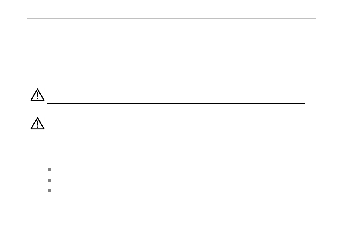
4. Tap t he Add >> button to add the selected
standard(s) to the Signal Standards
selected list.
5. Tap OK. The enabled standards are now
selectable from the main window Signal
Standards drop-down list.
NOTE. Limiting the number of enabled standards to just those that you regularly test makes it easier and faster to select a
standard from the Signal Standard drop-down list.
Installation
NetTek®YBT250 Quick Start User Manual 13
Page 30

Installation
14 NetTek®YBT250 Quick Start User Manual
Page 31

Getting Acquainted with Your Instrument
Instrument Elements
1. NetTek Y400 Analyzer Platform.
2. Battery compartment.
3. NetTek YBT250 Application Module.
4. Input/Output ports. (See page 17,
Input/Output Connectors (NetTek Y400
Platform).)
5. PCMCIA card ports.
6. Power and Status panel. (See page 16,
Power On/Stan dby and Status Panel.)
7. External adapter power connector. (See
page 4, Connecting the AC Adapt er.)
8. Touch screen.
GettingAcquaintedwithYourInstrument
NetTek®YBT250 Quick Start User Manual 15
Page 32

Getting Acquainted with Your Instrument
Power On/Standby and Status Panel
1. Power On/Standby button. Push to
power on or off the instrument. For
more information, access the online help:
Start > Help > Tektronix Basics >
Shutting Down the Instrument.
2. Reset button. Performs a hardware reset;
all programs and data loaded into volatile
memory are erased. Generally only used
to recover from a system lock-up. Use a
thin p robe to push the reset button.
3. Power/Display status. Green indicates
that the instrument is powered on. Amber
indicates that the instrument is powered o n
but the display is turned off (to conserve
power).
4. Battery status. Green indicates that the
instrument is connected to an external
power source and is charging installed
batteries. Red indicates a low battery.
No color indicates that the batte ries are
charged.
16 NetTek®YBT250 Quick Start User Manual
Page 33

Input/Output Connectors (NetTek Y400 Platform)
1. Microphone input
2. Headphone jack
3. Ethernet conn ector (RJ-45)
4. Serial RS-232 connector
5. PS/2 keybo ard connector
6. USB Host connector
7. USB Slave connector
See the Y400 NetTek Analyzer Setup Reference document (Tektronix part number 071-1430-XX) for more information on the
NetTek Y400 Analyzer Platform.
GettingAcquaintedwithYourInstrument
NetTek
®
YBT250 Quick Start User Manual 17
Page 34

Getting Acquainted with Your Instrument
NetTek YBT250 Module Signal Connectors
1. Timing Input. Co nnects to an external
timing reference signal, such as a BTS
Even Second Clock signal, or the timing
signal from a Tektronix YBGPS1 GPS
Timing Reference.
2. Frequency Reference Inpu t. Use an
external frequency reference signal to
improve measurement accuracy.
3. RF Input. The RF Input connects the
RF input signal source or measurement
antenna to the instrument.
Microsoft WindowsCE Elements
The Microsoft WindowsCE user interface is similar to other Microsoft Windows operating systems. You use standard Microsoft
Windows operations to start (run) applications, select and move objects, and open folders or files. For more Microsoft WindowsCE
information, access the online help: Start > Help > WindowsCE Basics.
The S tatus area, located at the bottom right of the screen, contains icons that display important information about the instrument
power status. For an explanation of all status area icons, access the online help: Start > Help > WindowsCE Basics >
Understanding Taskbar Icons.
18 NetTek
®
YBT250 Quick Start User Manual
Page 35

The User Interface
1. Command bar. (See page 20, The
Command Bar.)
2. Tuning controls. (See page 21, The
Tuning Controls.)
3. Measurement results. Shows the
waveform displays and measurement
results. The appearance of this area
changes depending on the selected
measurement mode and measurement
type.
4. External signal status buttons.(See
page 22, Th e External Signal Status
Buttons.)
5. Measurement mode bu ttons.(See
page 23, The Measurement Mode
Buttons.)
6. Parameter entry controls. (See page 24,
The Parameter Entry Controls.)
GettingAcquaintedwithYourInstrument
NetTek®YBT250 Quick Start User Manual 19
Page 36

Getting Acquainted with Your Instrument
The Command Bar
Contains the applica tion menus, as well as buttons for saving measurement results, opening the application setup dialog box,
and running/pausing the application.
Element Description
Menus. S ee the Online help topic Menus for information about the menu functions.
Save Results button. Saves the current measurement acquisition to a file. See the Online help
topic The Save & Export Tab for how to set file save parameters.
Edit button. Opens the Setup dialog box that contains instrument settings tabs. See the Online
help topic Setup Tabs for information on the setup dialog tabs.
Open button. Shows the Open dialog box that lists saved instrument setup files to load and
configure instrum ent settings. See the Online help topic The Setup Menu Tab for directions on how
to switch the button between the Edit and Open modes.
Run/Pause button. Runs or Pauses the current measurement acquisition.
Help button. Opens the online help. Online help is context-sensitive and normally displays a
help topic related to the current measurement mode or screen. If the current screen is not
context-sensitive, the instrument opens the Online help at the main help menu. Use the index, or do
a word search, to locate specific information.
20 NetTek®YBT250 Quick Start User Manual
Page 37

The Tuning Controls
Selects the signal standard, signal direction (uplink or downlink), measurement channel, and measurement frequency.
Element Description
GettingAcquaintedwithYourInstrument
The Signal Standard drop-down list displays the enabled signal standards from which you
select a standard to measure. (Se e page 12, Enabling Signal Standards.)
The Downlink and Uplink buttons change the Freq (MHz) setting to the forward link (downlink)
or reverse link (uplink) frequency of the cu rrent signal standard and channel. For W-CDMA
signals, the se buttons set th e corresponding forward or reverse channel number.
The C hannel button sets the channel number. The field next to the button shows the current
channel number. Tapping the button opens the numeric keypad, with which you enter
a channel number.
The current signal standard defines the available channel numbers. Setting the channel
number se ts the instrument measurement frequency to the appropriate value for the selected
signal standard and up or downlink mode setting.
The Freq (MHz) button sets the Measu remen t Frequency. The field next to the button
shows the frequency. Tapping the button opens the numeric keypad, with which you enter
a frequency value.
NetTek®YBT250 Quick Start User Manual 21
Page 38

Getting Acquainted with Your Instrument
The External Signal Status Buttons
Indicates status and sets GPS, measurement reference frequency source, and input signal attenuation or amplification values.
Element Description
The GPS sta tus button indicates the GPS signal lock status of an attached GPS r eceiver. The color indicates
the GPS receiver signal lock status. Tap this button to open the GPS setup tab. See the Online topic The GPS
Tab for more information.
The Measurement Reference Frequency status button indicates the measurement frequency reference source. Tap
this button to open the Inputs tab. Use this button if you connect an extern al measurement reference frequency
source to the instrument.
The ava ilable measurement reference frequency sources are the internal instrument frequency reference (F INT),
an external reference (F E XT), or a GPS-derived timing reference from the Tektronix YBGPS1 GPS Timing
Reference (F GPS). See the Online topic The Inputs Tab for more information.
The RF Input Signal Gain/Loss status button shows the external attenuator or amplifier status. Tap this button to
open the Inputs tab where you can set the input signal amplification or attenuation values. Use this button if you
connect an attenuator or amplifier to the input signal. See the Online topic The Inputs Tab for more information.
22 NetTek®YBT250 Quick Start User Manual
Page 39

The Measurement Mode Buttons
The Measurement Mo de buttons select the type of measurement or operation to perform.
Element Description
Select th e Signal Measurements button to take signal measurements including RF power, signal
quality, occupied bandwidth, carrier frequency, power vs. time, and others.
Select the Spectrum Measurements button to take spectrum and spectrogram measurements.
Select t he Interference Measurements button to take signal strength, audio demodulation, noise
floor, EMF, and signal scanner measurements.
Select the Measurement Sequencer button to display multiple measurements.
GettingAcquaintedwithYourInstrument
NetTek®YBT250 Quick Start User Manual 23
Page 40

Getting Acquainted with Your Instrument
The Parameter Entry Controls
The Parameter Entry controls (keypad and knob) let you en ter or change numeric values in selected fields. You can use either tool
to enter or change a value.
Element Description
The input control field shows the label for the field and the curren t value of the selected field
or object.
Tapthekeypadbuttontodisplayakeypadinwhichtoenteravalueintheselectedfield. The
keypad conten t changes to show the available entry functions for the selected item.
The knob control lets you scroll through and select from all available values.
1. Drag the knob circle left or right to quickly scroll through all available values and select a value.
2. Tap the arrows on the top half of the knob icon to step the value in large increments. The
increment value depends on the value type (channel or frequency).
3. Tap th e arrows on the bottom half of the knob icon to step the value in single unit increments.
24 NetTek®YBT250 Quick Start User Manual
Page 41

Getting Help
The ap plication includes a comprehe nsive Online help system. You access Online help using the following methods:
Online help element Description
Contents Index Online h elp Content and Index links. Every Online help topic includes a Contents and Index link.
GettingAcquaintedwithYourInstrument
Help button. Located at the top right of the screen, this button is available all the time. Tap this
button to display a help topic that is relevant to the c urrent measure m ent screen.
If the current screen is not context-sensitive, the application opens the Online help at the main help
menu. Use the index link, or do a word search, to locate specific information.
Help link text. On measurement screens, u nderlined blue text is help link text. Bold help link text at
the top of a measurement screen opens a topic describing how to take that measurement. Help
link text that is located next to a measurement or setting opens a topic relevan t to that particular
measurement or setting.
If the topic does not contain the information you were seeking , use these links to locate specific
information.
Tab or dialog box help button. This button is displayed at the bottom of ma ny setup tabs or dialog
boxes, and opens an Online help topic relevant to that tab or dialog b ox.
NetTek®YBT250 Quick Start User Manual 25
Page 42

Getting Acquainted with Your Instrument
26 NetTek®YBT250 Quick Start User Manual
Page 43
Operating Basics
Setting Up to Take a Measurement
Perform the following steps to set up the instrument to take a measurement. These steps apply for most types of measurements.
1. Connect a signal to the instrument.
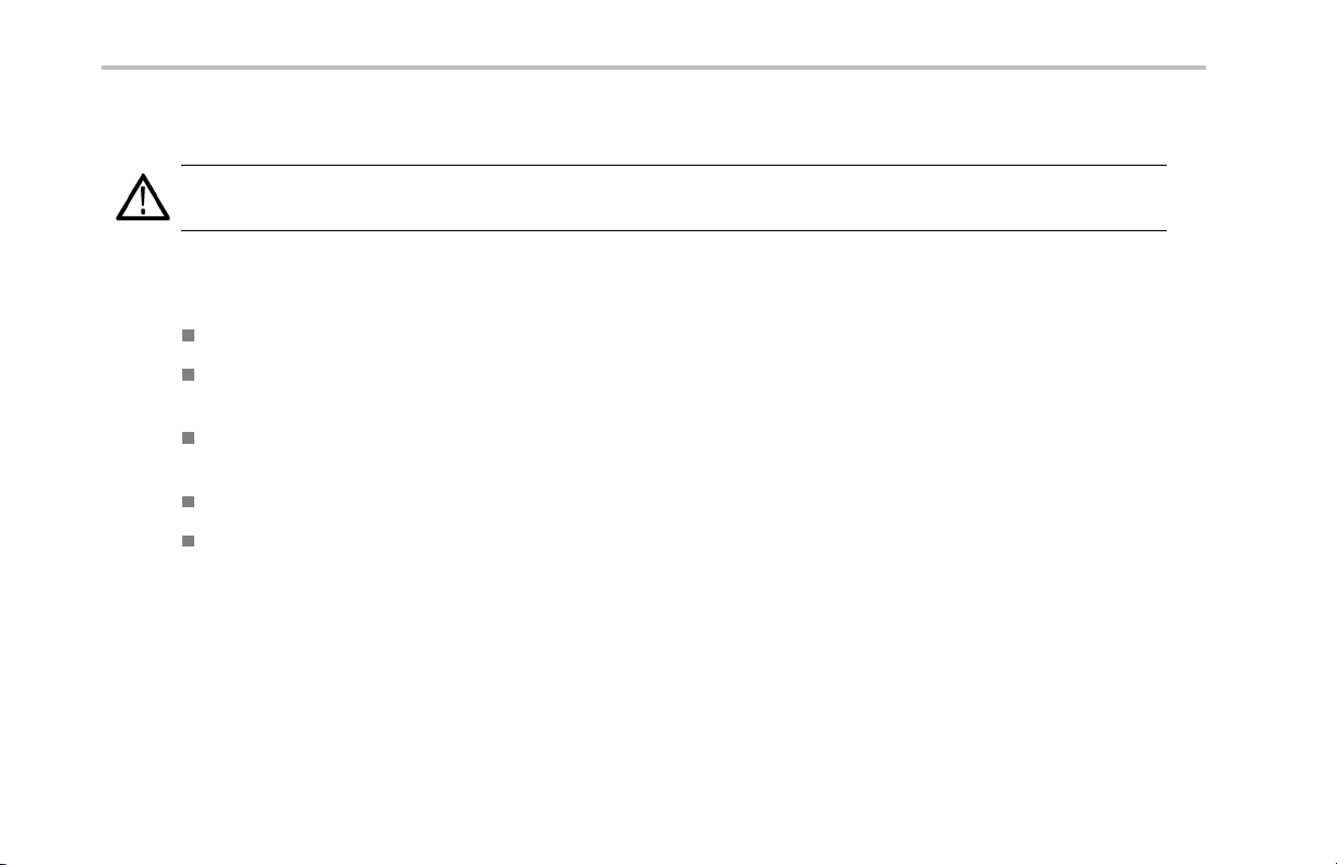
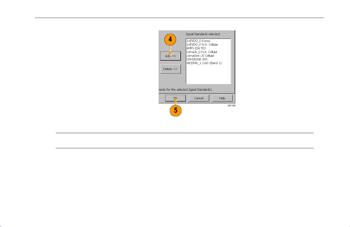
2. Tap t h e Signal Standard List arrow button
to open the signal standard list.
3. Tap a signal standard to select it. This
signal standard is used for measurements
until you change to a different signal
standard. (See page 12, Enabling Signal
Standards.)
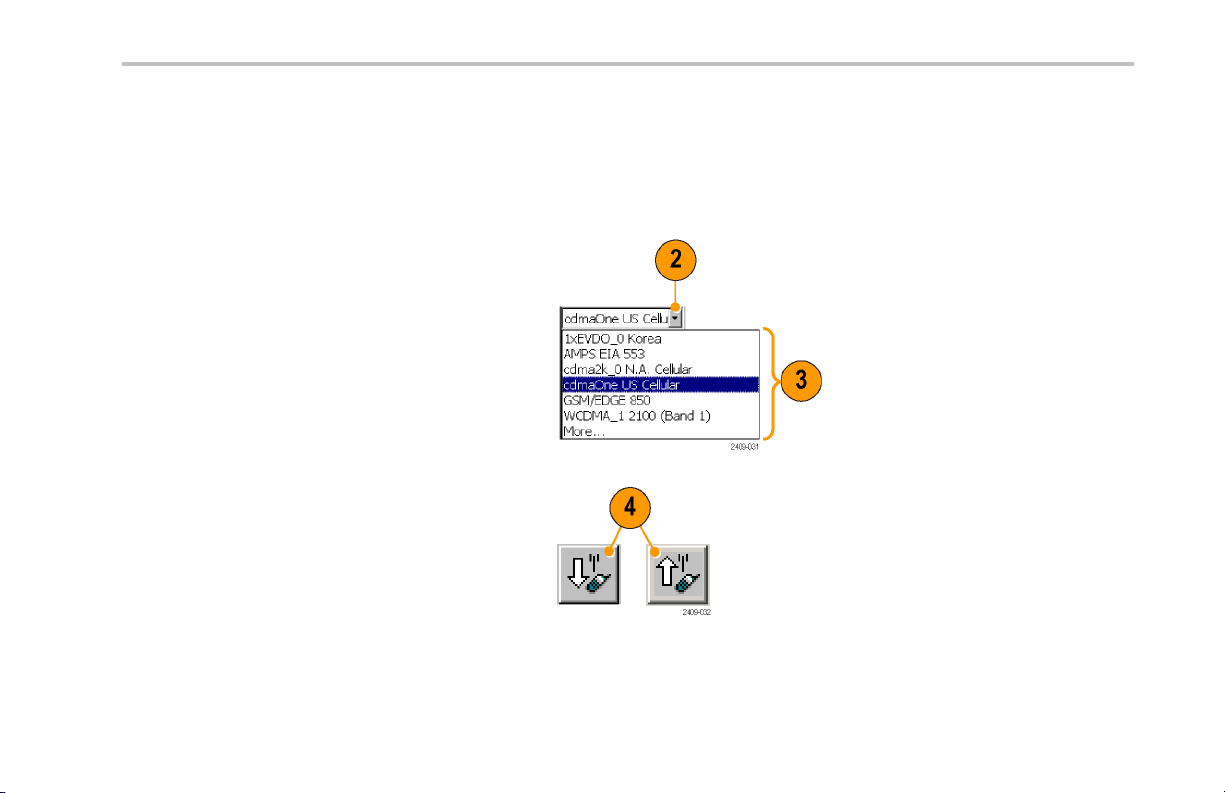
4. Tap the appropriate signal Uplink or
Downlink butto n for the measurement that
you are taking.
Operating Basics
NetTek®YBT250 Quick Start User Manual 27
Page 44

Operating Basics
Entering a Channel:
NOTE. You only need to enter a channel or a frequency; you do not need to enter both values.
5. Tap the Channel button to open the
keypad.
6. Enter a channel number.
7. You can also tap the List button to display
a list of available channels from which
to select a value. Channel numbers are
defined by the current signal standard.
If there is a corresponding frequency for the
entered channel number, the instrument
displays that frequency in the Freq (MHz)
field.
If you enter a channel number outside the
valid range, the instrument sets the channel
number to the closest valid number.
8. Tap OK to close the keypad or channel list
and set the channel value.
28 NetTek®YBT250 Quick Start User Manual
Page 45

Entering a Frequency:
NOTE. You only need to enter a chan nel or a frequency; you do not need to enter both values.
9. Tap the Freq (MHz) button to open the
keypad.
10. Use the keypad to enter a frequency v alue .
This sets the cente r frequency of the
measurement.
If there is a corresponding channel number
for the entered frequency, the instrument
displays that channel number in the
Channel field.
11. Tap a frequency unit button (such as GHz
or MHz) to close the keypad and set the
frequency value.
Operating Basics
NetTek®YBT250 Quick Start User Manual 29
Page 46

Operating Basics
Selecting a Measurement Mode:
12. Tap a measurement mode button. (See
page 23, The Measurement Mode Buttons.)
13. For Spectrum and Interference
measurements, select the tab of the
measurement that you want to take.
14. For Signal measurements, tap the Select
Measurement button, then tap the
measurement that you want to take.
30 NetTek®YBT250 Quick Start User Manual
Page 47

Setting Additional Measurement
Parameters:
15. Tap the Edit button to open the Setup
dialog box.
16. Tap the tab of the measurement parameters
that you want to set.
17. Select or enter the m easurement parameter
values.
18. Tap OK to close the Setup dialog box
and enable the measure ment parameter
settings.
Operating Basics
NetTek®YBT250 Quick Start User Manual 31
Page 48

Operating Basics
Signal Measurements
Taking a Signal Measurement
Signal measuremen ts include RF channel power, peak/average, carrier frequency, occupied bandwidth, signal quality, code power,
codograms, and pilot power. Available measurements depend on the current signal standard.
1. Set the instrument to measure a signal of
interest. (See page 27, Setting Up to Take
a Measurement.)
2. Tap t h e Signal Measurement button.
3. Tap th e Select Measurement button to
open the Select Signal Standard and
Measurement dialog box.
4. Tap the measurement button for which
you want to take measurements.
The instrument opens the s elected
measurement screen.
32 NetTek®YBT250 Quick Start User Manual
Page 49

5. Make any nece ssary setting changes on
the m easurement screen (if available). For
example, the cdma2000 Signal Quality
measurement lets you select the signal
type to use for measuring Signal Quality
(Pilot only or Auto detect active codes).
6. Tap the Edit button to open the Setup
dialog box and set additional measuremen t
parameters in the dialog box tabs.
Available parameters depend on the
current signa l standard and measurement
type. Not all measurements have setup
parameters.
Operating Basics
NetTek®YBT250 Quick Start User Manual 33
Page 50

Operating Basics
Spectrum Measurements
Displaying a Spectrum Waveform
1. Set the instrument to measure a signal of
interest. (See page 27, Setting Up to Take
a Measurement.)
2. Tap t he Spectrum button.
3. Tap th e Spectrum tab.
4. Tap t he AutoLevel button.
5. Tap the Span controls to change the
displayed frequency span to show the
waveform area of interest.
34 NetTek®YBT250 Quick Start User Manual
Page 51

Operating Basics
6. Tap t he Ref Lvl field or the Vertical Scale
field to select it.
7. Use the Parameter Entry controls to enter
or change the scale setting.
8. Use markers to take measurements
between different parts of the waveform.
(See page 3 6, Spectrum Waveform
Markers.)
NOTE. Ta p t h e Edit buttontoopentheSetup dialog box and set additional measurement parameters. Available parameters
depend on the current signal standard and measurement type. Not all measurements have setup parameters.
NetTek®YBT250 Quick Start User Manual 35
Page 52

Operating Basics
Spectrum Waveform Markers
Markers are visual icons that you position on a spectrum waveform to measure signal frequency and level values. You use the
markers to measure the value at a particular point on a waveform or to measure the difference between two markers (Marker 1
minus Marker 2). The markers follow the waveform level changes.
Each marker icon has an associated marker readout, displayed at the bottom of the Spectrum display. The marker readout shows
the marker icon symbol, the marker name, and the frequency and level values for the marker.
There are three markers available: the Trace marker (Trace), M1, and M2. The Trace m arke r changes the measurement
frequency to the location you select on the waveform. The M1 and M2 markers read the waveform frequency and level at the
location they are placed.
TurningMarkersOnandOff.
1. Tap View.
2. Tap Markers to turn marker display on or
off.
3. Markers consist of a marker icon that
is placed on a waveform, and a marker
readout that shows the signal frequency
and level at the marker icon position.
36 NetTek®YBT250 Quick Start User Manual
Page 53

Adding or Moving a Marker on a Waveform.
1. Tap the marker readout of the marker that
you want to add or move on the spectrum
waveform. The marker read out border
darkens to indicate that it is selected.
2. Tap the waveform where you want to add or
move the marker. The marker is positioned
on the waveform and the readou t shows
the signal values at the new location.
3. If necessary, use the Parameter Entry
controls to position the marker on the
waveform by changing the marker
frequency.
Operating Basics
NetTek®YBT250 Quick Start User Manual 37
Page 54

Operating Basics
Comparing Spectrum Waveform Traces
You can compare two live waveforms (derived from the single RF input signal), a live signal and a saved waveform, or two
saved waveforms.
Selecting a Waveform Trace.
1. Tap t he Traces button to toggle between
Trace 1 and Trace 2.
Comparing Live Waveform Traces.
1. Set the instrument to display the spectrum
waveform of interest. (See page 34,
Displaying a Spectrum Waveform.)
2. Tap t h e Traces button to select Trace 1.
38 NetTek®YBT250 Quick Start User Manual
Page 55

3. Tap the Trace 1 list button and then tap
a trace type to select it. The instrument
applies the selected operation to the RF
input signal and displays the results as the
trace 1 waveform.
4. Tap the Traces button again to select
Trace 2.
5. Tap th e Trace 2 list button and then tap a
trace type to select it.
The instrument applies the selected
operation to the input signal and displays
the result as the trace 2 wavefo rm, along
with the trace 1 waveform. The figure
shows Trace 1 as a Normal waveform and
Trace2asaMin Hold waveform.
Operating Basics
NetTek®YBT250 Quick Start User Manual 39
Page 56

Operating Basics
6. To make measurements between the
waveforms, use the View menu to set
which markers are on which trace.
40 NetTek®YBT250 Quick Start User Manual
Page 57

Operating Basics
Comparing a Live Waveform to a Saved Waveform.
NOTE. The current instrument measurement settings must match the instrument settings used to capture the saved waveform.
1. Set the instrument to display a spectrum
waveform of interest. (See page 34,
Displaying a Spectrum Waveform.)
2. Tap t he Traces button to select Trace 1.
3. Tap th e Trace 1 list button and then tap a
trace type to select it.
4. Tap t he Traces button to select Trace 2.
NetTek®YBT250 Quick Start User Manual 41
Page 58

Operating Basics
5. Tap t h e Trace 2 list button and tap Saved
to open the Trace 2 & Mask setup tab.
6. Tap Saved Trace.
7. Enter a file path and name of a saved
waveform file, or tap the Browse button to
navigate to and select the saved waveform
to open.
8. Tap OK. The instrument displays the saved
waveform as th e Trace 2 waveform. You
can use markers to make measurements
between the waveforms.
42 NetTek®YBT250 Quick Start User Manual
Page 59

Operating Basics
Comparing Two Saved Waveform Traces.
NOTE. Waveform traces are saved with the s etting s in effect at the time the trace is saved. When a saved trace is displayed, the
stored se ttings values are shown for reference, though no actual instrument settings ch ange. As soon as you tap the Run button to
return to making new acquisitions, the display settin gs are restored to what they were before the saved trace was opened.
1. Select File > Compare Saved.
2. Navigate to and select the first wave form
file to load.
3. Tap OK to open the Select second result
file to compare dialog box (it looks exactly
thesameasthefirst dialog box).
4. Navigate to and select the second
waveform file to load.
5. Tap OK to select the second file and close
the dialog box. The instrument displays
both waveforms.
6. After viewing the waveforms, tap the Run
button to return the instrument to taking
measurements.
NetTek®YBT250 Quick Start User Manual 43
Page 60

Operating Basics
Displaying a Spectrogram
A spectrogram shows how the signal level changes over time. It can be very useful in finding intermittent signal level variations.
1. Set the instrument to display the spectrum
waveform of interest. (See page 34,
Displaying a Spectrum Waveform.)
2. Tap t h e Spectrogram tab. The
Spectrogram display updates from the
bottom to the top of the display.
3. Tap the Updates button to display a
dialog box where you can change the
spectrogram measurement update rate and
enable automatic saving of data when a
screen is full (80 data record acquisitions).
4. The Data Record readout shows the
time and date sta mp of the spectrogram
record located at the record cursor (white
horizontal line). To change the record
cursor position, tap the Data Record field
and use the keypad or knob to move the
record cursor.
44 NetTek®YBT250 Quick Start User Manual
Page 61

Interference Measurements
The Interference measurement capabilities provide functions to help identify interference signals, demodulate AM or F M audio
signals, assess the strength of an interfering signal, measure the noise floor on receive channels, and display PN offset or
scrambling code data for spe cified chan nels.
Tab Description
Identify Display information on the likely modulation type of a selected signal. Identify can differentiate
between CDMA, W-CDMA, GSM, IS-136, and analog signal modu lation types. (See page 46,
Identifying a Signal.)
Strength Locate an interfering signal by using a directional antenna and listening to an audio tone that
corresponds to the signal level. (See page 48, Locating the Direction o f a Signal.)
Audio
Noise
EMF
Scan Display PN offset or scrambling code data for specified channels. (See page 53, Channel
Demodulate an AM or FM signal to help identify traffic type. (See page 49, Listening to the Audio
Content of a Signal.)
Measure the noise floor on receive channels. (See page 51, Taking a Noise Floor Measurement.)
Measure RF field strength, such as when assessing the strength of an interfering signal. (See
page 52, Measuring EMF.)
Scanners.)
Operating Basics
NetTek®YBT250 Quick Start User Manual 45
Page 62

Operating Basics
Identifying a Signal
1. Set the instrument to display the spectrum
waveform of interest. (See page 34,
Displaying a Spectrum Waveform.)
2. Tap t h e Interference button, and then tap
the Identify tab.
46 NetTek®YBT250 Quick Start User Manual
Page 63
3. Tap the trace of the interfering signal to
set the measurement frequency. Try to
set the measurement frequency to the
center of the signal. You can also enter
the frequency value.
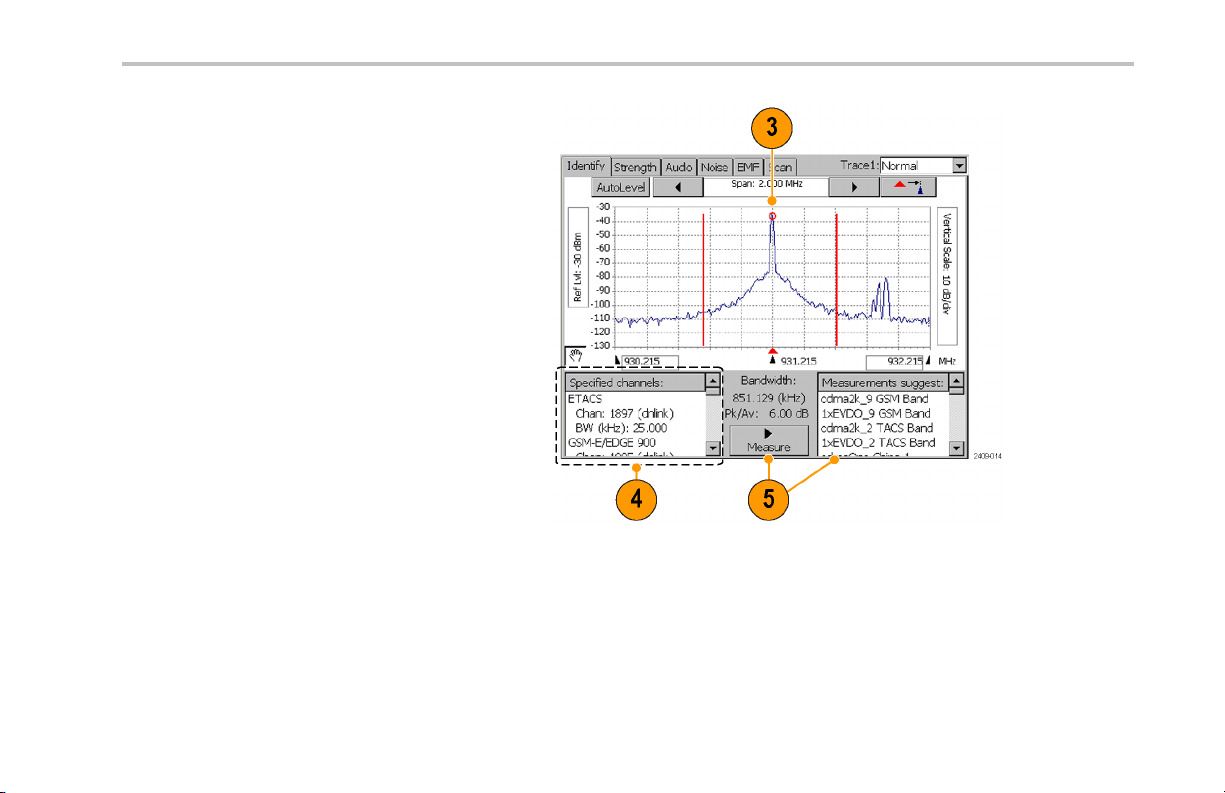
4. The Specified Channels list displays
any signal standards that have channels
defined at the measurement frequency.
5. Tap Measure. The instrument performs a
series of measurements to identify which
signal standard the signal’s characteristics
most closely match and displays possible
matches in the Measurements suggest
results box. The signals are sort ed by
frequency, with the signal that most closely
matches the measurement frequency
located at the top of the list. The instrument
also lists bandwidth and level information
above the Measure button.
Operating Basics
NetTek®YBT250 Quick Start User Manual 47
Page 64

Operating Basics
Locating the Direction of a Signal
1. Connect a directional antenna to the
instrument.
2. Set the instrument to display the spectrum
waveform of interest. (See page 34,
Displaying a Spectrum Waveform.)
3. Tap t h e Interference button, and th en tap
the Strength tab.
4. Tap the trace of the interfering signal to
set the measurement frequency. You
can use the keypad or knob to adjust the
measurement frequency.
5. Point the directional antenna in different
directions. As you change the direction of
the antenna, the audible tone and beep
(if selected), and th e Strength bar graph
change to indicate signal strength. The
signal of interest is located in the direction
that results in the strongest signal.
6. Tap Fast Update to improve audio tone
response, at the expense of a reduced
screen update rate.
48 NetTek®YBT250 Quick Start User Manual
Page 65

Listening to the Audio Content of a Signal
1. Set the instrument to display the spectrum
waveform of interest. (See page 34,
Displaying a Spectrum Waveform.)
2. Tap th e Interference button, and then tap
the Audio tab.
Operating Basics
NetTek®YBT250 Quick Start User Manual 49
Page 66

Operating Basics
3. Tap the trace of the interfering signal to
set the measurement frequency. You
can use the keypad or knob to adjust the
measurement frequency.
4. Tap the different Demodulation types and
listen to the resultant audio (if any). A
station ID can be particularly helpful when
the interfering signal is a radio or broadcast
television station. You may also be able
to discriminate between possible sources
by listening to the characteristic sounds
of paging, video, control signals or the
harmonics of other common signals.
50 NetTek®YBT250 Quick Start User Manual
Page 67

Operating Basics
Taking a Noise Floor Meas urement
Noise fl oor measures all the RF Power coming into the receive antenna within the frequency band of the selected channel. The
noise floor is the power integrated across the selected channel. To make an accurate measurement, you must measure the noise
floor on a disabled channel (a channel that is not carrying live traffic).
1. Connect a signal from a BTS receiver test
port to the instrume nt.
2. Set the instrument to display the spectrum
waveform of interest. (See page 34,
Displaying a Spectrum Waveform.)
3. Tap th e Reverse (up) link button.
4. Tap th e Interference button, and then tap
the Noise tab.
5. Tap the trace of the interfering signal to
set the measurement frequency. You
can use the keypad or knob to adjust the
measurement frequency.
NetTek®YBT250 Quick Start User Manual 51
Page 68

Operating Basics
Measuring EMF
EMF fi eld strength is a measure of the absolute electromagnetic power of a signal at a particular frequency and bandwidth at the
antenna, without reference to signal modulation.
1. Connect a hand-held antenna and filter (if
used) to the instrument.
2. Set the instrument to display the spectrum
waveform of interest. (See page 34,
Displaying a Spectrum Waveform.)
3. Tap t he Downlink button.
4. Tap t h e Interference button, and th en tap
the EMF tab.
52 NetTek®YBT250 Quick Start User Manual
Page 69

Operating Basics
Channel Scanners
Channel scanner measurements display channel-specific measurements on GSM, cdma200, 1xEV-DO, and W-CMA standards.
Scanner measurements are for off-air reception using an antenna, and measure only downlink signals.
1. Connect a hand-held antenna (and filter
if used) to the instrument RF INPUT
connector.
2. Set the instrument to measure a signal of
interest.(Seepage27,Setting Up to Take
a Measurement.)
3. Tap th e Downlink button.
4. Tap th e Interference button, and then tap
the Scan tab.
NetTek®YBT250 Quick Start User Manual 53
Page 70

Operating Basics
Scanner displays consist of two parts.
The upper display is a plot of channel,
scrambling code, or PN offset codes and
signal strength. The lower display provides
more information on individual channels,
scrambling code, or PN offsets.
5. Use available controls to set measurement
functions.
NOTE. To make accurate measurements, use a receive ante nna with a frequency response and ba ndwidth that is appropriate for
the channel you are measuring. Use a high quality, low-loss Band Pass Filter (BPF) to reject signals outside the signal band.
If you take measurements near a high-power transmitter, such as commercial TV or radio, a BPF may be necessary for the
scanner to produce usable results.
54 NetTek®YBT250 Quick Start User Manual
Page 71

Operating Basics
Scanner Tadd/Tdrop Markers. Tadd and Tdrop are horizontal markers that you can set on 1xEV-DO and cdma2000 PN
Scanner measurements to visually indicate add or drop signal power levels. Using these markers lets you quickly identify PN codes
that are within defined add or drop ranges. The Tadd/Tdrop horizontal markers are visual aids only, and do not cause the instrument
to display warnings when signals are above or below the set levels.
1. Select View > PN Scanner Tadd/Trop
Markers to display the markers on the
scanner measurement graph.
2. Tap the Tadd or Tdrop readout and use
the keypad or knob control to change the
marker level value.
NetTek®YBT250 Quick Start User Manual 55
Page 72

Operating Basics
Custom Scanner Code Labels. The Scanner Code Label Editor lets you add unique labels to the graphs of 1xEV-DO and
cdma2000 PN scanners, and the W-CDMA scrambling code analyzer. Once you have created labels, tapping a bar graph of a
PN offset or scrambling code displays the label assigned to that PN offset or scrambling code, directly be low the graph. Using
labels lets you quickly iden tify the source of a particular code.
1. Select View > PN Offset Labels or
View > Scrambling CodeLabels to enable
viewing scanner labels on the scanner
measurement graph.
2. Tap a bar graph plot to display the
custom label assigned to that PN offset or
scrambling code.
See the Online help topic Scanner Code Labels Overview for information on creating, saving a nd using custom scanner code labels.
56 NetTek
®
YBT250 Quick Start User Manual
Page 73

Displaying Multiple Measurements
The Measurement Sequencer mode lets you display one or more signal measurements for a single standard an d channel/frequency.
The instrument sequences through each of the selected measurements and displays the results on the Sequencer screen.
1. Set the instrument to measure a signal of
interest.(Seepage27,Setting Up to Take
a Measurement.)
2. Tap th e Sequencer button.
3. Tap t he Select Measurements button.
4. Select which measurements to display in
the Sequencer screen, and then click OK.
Available measurements depend on the
current signal standard.
Operating Basics
NetTek®YBT250 Quick Start User Manual 57
Page 74

Operating Basics
5. The instrument displays the selected
measurements, sequentially updating the
measurement values.
6. Out-of-limit me asurements are marked by
aredblockwithanupordownarrow.
7. Messages may appear in the measurement
name gray bar to indicate measurement
errors or conditions.
Saving and Loading Sequencer Measurements and Results
You can save measurement sequences for each standa rd and then recall these sequences later for reu se. To save a measurement
sequence, tap Setup > Save, enter a name, and tap OK.
You can use the file menu to save, export, or print the numeric Sequencer data, including error information and the timestamp (the
time of the last individual measurement taken). Note that if yo u export a screen, a picture of only what shows on the screen is
exported. If there is a scroll bar visible, then some measurement results are hidden and are not exported. To avoid this proble m ,
use File > Export Results As, or scroll down and export a second view of the screen.
To load a saved sequence, tap Setup > Open, navigate to and select a saved sequence settings file, and tap OK.
58 NetTek
®
YBT250 Quick Start User Manual
Page 75

Specifications
This section lists the electrical, environmental, and physical specifications of the NetTek YBT250. All specifications are guaranteed
unless labeled “typical”. Typical specifications are provided for your convenience and are not guaranteed.
Table 1: G eneral characteristics
Characteristic Description
RF Input
Input F reque ncy Range 30 MHz – 2500 MHz
Input Impedance
Signal Amplitude for
Modulation Measurements
Signal Amplitude for
Spectral Display, typical
Input Overload Detect >1 W (+30 dBm) CW or pea k envelope power
Maximum Input Power
without Damaging
Instrument
Coupling AC for all measurements and spectral display modes
Specifications
50 ohms (nominal)
–50 dBm to +30 dBm for CW-like or peak envelope power
Measurements may be outside this range but accuracy is not guaranteed
CW or peak envelope power:
–144 dBm to +30 dBm, 200 MHz to 2.0 GHz
–142 dBm to +30 dBm, 2.0 GHz to 2.2 GHz
–139 dBm to +30 dBm, 2.2 GHz to 2.5 GHz
Levels apply wh en using 100 Hz resolution bandwidth
50 W CW or peak envelop e power
NetTek®YBT250 Quick Start User Manual 59
Page 76

Specifications
Table 1: General characteristics (cont.)
Characteristic Description
External Frequency
Reference Input
Maximum Working Voltage
Spurious In put Signals To meet modulation measu rement specifications:
Impedance
Input Connector 50 ohm BNC
Frequency Range
Level Range –15 dBm to +15 dBm
15 V (DC + peak AC)
(Total power of interest - Total power in spurious) > 35 dB
or
| Center frequency of signal of interest - center frequency of spurious signal | > 1.4 MHz
and
(Total power of interest - Total power in all spurious) ≥ –3 dB
1500 ohms (nominal)
Anymultipleof1MHzupto15MHzinclusive,±1ppm
Any multiple of 1.2288 MHz up to 19.6608 MHz inclusive, ± 1 ppm
2.048 MHz ± 1 ppm
4.8 MHz ± 1 ppm
dBm levels assume 50 oh m source
60 NetTek®YBT250 Quick Start User Manual
Page 77

Table 1: General characteristics (cont.)
Characteristic Description
Maximum Input Level
without Damage
Coupling AC
Working Voltage
Lock Time < 15 seconds
Timing Input
Impedance
Minimum High Threshold 2.0 V
Maximum Low Threshold 0.8 V
Minimum H igh Time 10 ns
Minimum Low Time 10 ns
Maximum Input Level
without Damage
Coupling DC
Timing Error ± 10 ppm
± 3 V peak continuous
3 V (DC + peak AC)
10 kΩ
± 5 V peak continuous
Specifications
NetTek®YBT250 Quick Start User Manual 61
Page 78

Specifications
Table 1: General characteristics (cont.)
Characteristic Description
Internal Time Base
Characteristics
Signal Path Characteristics
Error
Phase Noise
Noise Figure 1 kHz resolution bandwidth:
Displayed Average Noise
Level (DANL), typical
± 0.5 ppm drift from 0 ° C to 50 °C
± 1.0 ppm aging/year
Ten minute warm-up period required to meet accuracy specification.
Users can conne ct the External Reference input to a freq uency source and obtain a user
correction value. This value will be used to correct time base errors in measurements to
the accuracy of the external reference. The internal time base will continue to drift with
temperature and age as specified above.
≤ –75 dBc/Hz @ 20 kHz carrier offset
≤10 dB, 200 MHz to 2000 MHz
≤12 dB typical, 2000 MHz to 2200 MHz
≤15 dB typical, 2200 MHz to 2500 MHz
10 Hz RBW: –152 dBm, 200 MHz to 2000 MHz
100 Hz RBW: –145 dBm, 200 MHz to 2000 MHz
1 kHz RBW: –135 dBm, 200 MHz to 2000 MHz
62 NetTek®YBT250 Quick Start User Manual
Page 79

Table 2: Measurement characteristics
Measurement Description
External
Attenuation
Code Domain
Power (cdmaOne,
cdma2000,
W-CDMA)
Units dB relative to Pilot Power or Total Power
Resolution 0.1 dB
Accuracy
User Selectable ON/OFF
Attenuation=–30dBto+80 dB
Measures the power in each of the Walsh cod es (64 in cdmaOne, 12 8 in cdma2000) used in a CDMA
signal.
Measures the power in each of (up to 512) OVSF codes used in a W-CDMA signal.
cdmaOne and cdma2000: ± 1 dB code domain power level > –20 dB relative to total power, using the
recommended TIA/EIA-IS-97-D pilot level of –;7.0 dB (20%) relative to total power.
W-CDMA: ± 1 dB Code domain power level > –20 dB relative to total power, using W-CDMA 3GPP
Test Model 3.
Reference information: ± 2.5 dB for –27 dB < CDP < –20 dB relative to total power in band classes
0-6 (cdmaOne, cdma2000).
± 2.5 dB for –27 dB < CDP < –20 dB relative to total power (W-CDMA).
Specifications
NetTek®YBT250 Quick Start User Manual 63
Page 80

Specifications
Table 3: Spectral analysis
Characteristic Description
Measurement
Frequency
Frequency Span Sets the freque ncy range covered by the spectral display.
Resolution Bandwidth
(RBW)
Sets the measurement frequency of the display. The measurement fre quency can be set by either
entering a specifi c frequency or by selecting a channel number.
Units
Resolution 1 kHz 1 channel
Range 30 MHz to 2500 MHz
Units
Resolution 1 kHz
Range 10 kHz to 2470 MHz, continuously variable or 1-2-5 steps
Units
Resolution Uses 1-3 steps to cover the range
Range 10Hzto6MHz
MegaHertz (MHz) or Channel Number
kiloHertz (kHz), MegaHertz (MHz)
Width of the resolution bandwidth filter
Hertz (Hz), kiloHertz (kHz), MegaHertz (MHz)
When in Auto mode, the instrument automatically sets the RBW. The RBW is set a s a combination
of 1-3 steps at the 1, 2, 5 span settings, and a linear range between 1, 2, 5 span settings, for
a nominal value of approximately span/125.
64 NetTek®YBT250 Quick Start User Manual
Page 81

Table 3: Spectral analysis (cont.)
Characteristic Description
Reference Level The power level indicated by the top line of the spectral display
Units dBm
Resolution 1 dBm
Range –100 dBm to +30 dBm
Spectral Display
Amplitude
Units
Resolution 0.1 dB
Accuracy ± 1.25 dB, –20 dBm to +30 dBm
dB relative to Reference Level
± 2.0 dB, –80 dBm to –20 dBm
± 2.75 dB, –120 dBm to –80 dBm
± 5 dB –134 dBm < Input < –120 dBm, typical
Accuracy specifications apply only for spans less than 1000 MHz and to CW-like signals.
Specifications
NetTek®YBT250 Quick Start User Manual 65
Page 82

Specifications
Table 3: Spectral analysis (cont.)
Characteristic Description
Vertical Scale Factor
Units 1 dB to 10 dB in 1 dB increments
Display Modes Normal: updates display with each new result
Max Hold: updates displayed point only if new point > old point
Min Hold: updates displayed point only if new point < old point
Max/Min Hold: displays a bar between Max Hold and Min Hold
Average: displays average of N (specified by user) results
Reference information: Average is calculated as follows: Th e last N values are saved in memory;
when a new result is available, the earliest result of the N stored values is discarded, the new
average is calculated from the stored values. If the number of results is less than N, then all of
the results are averaged together.
Number of Averages
Spurious Free
Dynamic Range
(external signal
related)
1 ≤ N ≤ 99
IM3 better tha n –70 dBc typical, 100 MHz to 2500 MHz
2nd Harmonic better than –60 dBc, typical
66 NetTek®YBT250 Quick Start User Manual
Page 83

Table 3: Spectral analysis (cont.)
Characteristic Description
Residual Spurious
Signals
–125 dBm at BTS Rx frequencies (776–794, 806–849, 872–940, 1453–1465, 1525–1549,
1710–1785, 1840–1910,1920–1980) MHz and GPS frequencies (L1 1570.3–1580.5, L2
1222.5–1232.8, L5 1171.4–1181.6) MHz
–115 dBm at BTS Tx frequencies (746–764, 832–834, 840–960, 1477–1513, 1805–1880,
1930–1990, 2110–2170) MHz
–95 dBm at frequencies not listed above, except from 1155–1168 MHz: -20 dBm in spans above
10 MHz, 1155 MHz–1175 MHz
Table 4: Interference analysis characteristics
Characteristic Description
Noise Floor
Measurement
Units dBm
Resolution 0.1 dB
Accuracy ± 3 dB typical
AM Demodulation
Measurement
Frequency
Measures the interference power that is coming into the receiver antenna for any standard.
Measurement defaults to uplink channel when specified by channel number.
Provides an audio output signal after AM demodulation of the user-selected signal to use for
identifying a signal.
30 MHz to 2500 MHz with 1 kHz resolution
Specifications
NetTek®YBT250 Quick Start User Manual 67
Page 84

Specifications
Table 4: Interference analysis characteristics (cont.)
Characteristic Descrip tion
FM Demodulation
Input Signal Level
Measurement
Bandwidth
Audio Output
Bandwidth
Run Time 4 seconds per activation
Measurement
Frequency
Input Signal Level
Maximum Signal
Deviation
Measurement
Bandwidth
Audio Output
Bandwidth
Run Time 4 seconds per activation
–100 dBm minimum
8kHz
4kHz
Provides an audio output signal after FM demodulation of the user-selected signal to use for
identifying a signal.
30 MHz to 2500 MHz with 1 kHz resolution
-100 dBm minimum
Up to 100 kHz
8 kHz, 15 kHz, 75 kHz, 200 kHz; selected by user
4 kHz for Measurement BW = 8 kHz, 15 kHz
15 kHz for Measurement BW = 75 kHz, 200 kHz
68 NetTek®YBT250 Quick Start User Manual
Page 85

Table 4: Interference analysis characteristics (cont.)
Characteristic Description
Signal Strength Indicator Provides an audio tone and a visual display that vary with the strength of the selected signal.
Measurement
Frequency
Input Signal Level
Measurement
Bandwidth
Tone Type Variable beep rate, based on signal strength
30 MHz to 2500 MHz with 1 kHz resolution
–110 dBm minimum
Up to 10 MHz, dependent on span setting
Variable frequency tone, based on signal strength
Table 5: Scanner characteristics
Characteristic Description
W-CDMA Scrambling
Code Analyzer
Input Signal Range
Units and Resolution Io , Ec: dBm
Detects scrambling codes and pilot channel power levels of received co-channel W-CDMA
downlink signals.
–117 to +30 dBm, typical
Ec/Io: dB
0.1 dB
Specifications
NetTek®YBT250 Quick Start User Manual 69
Page 86

Specifications
Table 5: Scanner characteristics (cont.)
Characteristic Descrip tion
cdma2000 PN Scanner Detects PN Offset, Tau (Timing Error) and Pilot Channel power levels of multiple co-channel
Accuracy Ec:
±2 dB for Ec ≥ –102 dBm and Ec/Io ≥ –12 dB, typical
±3 dB for Ec ≥ –112 dBm and Ec/Io ≥ –14 dB, typical
Display C ont rols Sort by Power (descending Ec value)
Sort by Scrambling Code (ascending SC index)
Lock (set) current Scrambling Code set
cdmaOne and/or cdma2000 forward link signals.
Input Signal Range
Units Io, Ec: dBm
Resolution
–120 to +30 dBm, typical
Ec/Io: dB
PN Offset: PN index (0 to 511)
Tau: chips
Ec, Io, Ec/Io: 0.1 dB
PN Offset: 1 PN
Tau: 0.1 chip
70 NetTek®YBT250 Quick Start User Manual
Page 87

Specifications
Table 5: Scanner characteristics (cont.)
Characteristic Description
Accuracy Ec:
±2 dB for Ec ≥ –95 dBm and Ec/Io ≥ –8 dB, typical
±3 dB for Ec ≥ –110 dBm and Ec/Io ≥ –12 dB, typical
Tau:
0.5 chip, of highest power multipath component of each detected PNOS, relative to input timing
reference (ESC or YBGPS1), typical.
Display C ontrols Sort by Power (descending Ec value)
Sort by PN offset (ascending offset values)
Lock (set) current PN Offset values
1xEV-DO PN Scanner Detects PN Offset, Tau (Timing Error) and Pilot Channel power levels o f multiple co-channel
1xEV-DO f orward link signals. Up to 10 PN offsets are displayed.
Io: The total received power in the pilot intervals of the signal, within the signal bandwidth
(1.23 MHz).
Ec: The absolute power level of the detected pilot at the indicated PN Offset, in dBm.
Input Signal Range
Units Io, Ec: dBm
–120 to +30 dBm, typical
Ec/Io: dB
PN Offset: PN index (0 to 511)
Tau: c h i ps
NetTek®YBT250 Quick Start User Manual 71
Page 88

Specifications
Table 5: Scanner characteristics (cont.)
Characteristic Descrip tion
GSM Channel Scan ner The GSM channel scanner displays channel powe r and related information on a maximum of 128
Resolution
Accuracy, typical Ec:
Display C ont rols Sort by Power (descending Ec value)
Input Signal Range
Ec, Io, Ec/Io: 0.1 dB
PN Offset: 1 PN
Tau: 0.1 chip
± 2.5 dB for Ec ≥ –95 dBm and Ec/Io ≥ –8 dB
± 3.5 dB for Ec ≥ –110 dBm and Ec/Io ≥ –12 dB
Tau:
±0.5 chip, of highest power multipath component of each detected PNOS, relative to input timing
reference (ESC or YBGPS1)
Sort by PN offset (ascending offset values)
Lock (set) current PN Offset values
GSM forward link signals.
Displays Chan nel, Frequency, Peak Power, Traffic Type, C/I, and BSIC
The scann er is intended for off-air reception using an antenna, and measures only forward (down)
link signals. This measurement requires that YBT250 option GS1 is installed.
–120 to +30 dBm, typical
72 NetTek®YBT250 Quick Start User Manual
Page 89

Table 5: Scanner characteristics (cont.)
Characteristic Description
Units Frequency: MHz
Peak Power: dBm
C/I: dB
Resolution Frequency: 0.001 MHz
Peak Power: 0.1 dBm
C/I: 0.1 dB
Accuracy, typical
Display C ontrols AutoLevel (graph)
± 1 dB, –20 dBm to +30 dBm, ± 0.75 dB for identified GSM channels
The center frequency is derived from the channel number.
C/I is derived from EVM using the following equation:
C/I = –20 * log10(EVM/100)
Sort table by power or frequency
Start and stop channel select
Peak hold
Specifications
NetTek®YBT250 Quick Start User Manual 73
Page 90

Specifications
Table 5: Scanner characteristics (cont.)
Characteristic Descrip tion
TD-SCDMA Scanner Detects Sync code index, and DwPts Channel power levels of multiple co-channel TD-SCDMA
forward link signals. Up to 10 Sync codes are displayed.
Io: The total received power in the DwPts of the signal, within the signal bandwidth (1.6 MHz), in
dBm.
Ec: The absolute power level of the detected DwPts a t the indicated Sync Code, in dBm.
Input Signal Range
Units Io, Ec: dBm
Resolution
Accuracy, typical Ec:
Display C ont rols Sort by Power (descending Ec value)
–120 to +30 dBm, typical
Ec/Io: dB
Sync Code: Sync Code index (0 to 31)
Ec, Io, Ec/Io: 0.1 dB
Sync Code index: 1 code index offset
± 2.0 dB for Ec ≥ –85 dBm and Ec/Io ≥ –8 dB
± 3.5 dB for Ec ≥ –105 dBm and Ec/Io ≥ –12 dB
Sort by Sync Code (ascending offset values)
Lock (set) current Sync Code values
74 NetTek®YBT250 Quick Start User Manual
Page 91

Specifications
Table 6: Signal measurem ent characteristics
Characteristic Description
RF Channel Power Measures the average RF power in a user-defined channel. The default value of channel bandwidth
is taken from the selected standard. The acceptable values for channel numbers are taken from the
selected standard. The user can input the channel center frequency instead of the channel number.
Units and Resolution
Accuracy ± 0.75 dB: –20 dBm to +30 dBm, ± 0.5 dB typical
RF Power (GSM/EDGE) Measures the average RF power of the useful part of a GSM or EDGE burst (GMSK or 8-PSK
Units and Resolution
Accuracy
Watts (W), dBm
3 significant digits fo r W; 0.1 dB for dBm units
±1.25dB:–80dBmto–20dBm,±1.0dBtypical
Reference information: Accuracy is guaranteed fo r input signals between –80 and +30 dBm total
power (CW or peak envelope). Accuracy specificat ion is typical down to –120 dBm total power.
modulation), as determined by the location of the burst Training Sequence.
dBm: 0.01 dB for dBm units
For GSM or EDGE (GMSK or 8-PSK modulation) burst signals, the RF power measurement
accuracy is:
± 1.0 dB: –20 dBm to +30 dBm, ± 0.75 dB typical
± 1.5 dB: –80 dBm to -20 dBm, ± 1.25 dB typical
Reference information: Burst timing is determined from the location of the burst Training Sequence.
If Burst timing cannot be found, the power measurement will be done on an arbitrarily selected
segment of the signal equal to the useful part of a slot.
NetTek®YBT250 Quick Start User Manual 75
Page 92

Specifications
Table 6: Signal measurement characteristics (cont.)
Characteristic Description
RF P ower (1xEV-DO) Measures the RF power in the Pilot, MAC, and Data intervals of a 1xEV-D0 timeslot.
RF Power (TD-SCDMA) Measures the average RF power on individual timeslots (excluding the guard period) as determined
Units and Resolution
Accuracy For burst signals, the RF power measurement accuracy is:
Units and Resolution
Accuracy For burst signals, the RF power measurement accuracy is:
dBm: 0.01 dB for dBm units
± 1.0 dB: –20 dBm to +30 dBm, ± 0.75 dB typ ica l
± 1.5 dB: –80 dBm to –20 dBm, ± 1.25 dB typical
by the location of the downlink pilot timeslot (DwPTS).
dBm: 0.01 dB for dBm units
± 1.0 dB: –20 dBm to +30 dBm, ± 0.75 dB typ ica l
± 1.5 dB: –80 dBm to –20 dBm, ± 1.25 dB typical
Reference information: Burst timing is determined from the power envelope profile of the DwPTS.
If the DwPTS cannot be found, an error message is displayed.
76 NetTek®YBT250 Quick Start User Manual
Page 93

Table 6: Signal measurement characteristics (cont.)
Characteristic Description
RF Channel Carrier
Frequency
Units and Resolution
Accuracy
Accuracy using
YBGPS1 GPS Timing
Reference
Measures the frequency of the carrier in the user selected channel. The user can enter a channel
number or frequency.
MegaHertz (MHz): 1 Hz
± (10 Hz + Time Base Error), 99% confidence interval
W-CDMA: ± (12 Hz + Time Base Error), 99% confidence interval
Note: The carrier frequency mus t be within 10 kHz of the expected value, except:
W-CDMA, 1xEV-DO, and GSM/EDGE: within 5 kHz
IS-136: within 1.5 kHz
W-CDMA3GPPTestModel4
± (10 Hz + 0.015 ppm), typical
Note: The carrier frequency mus t be within 10 kHz of the expected value, except:
W-CDMA, 1xEV-DO, and GSM/EDGE: within 5 kHz
IS-136: within 1.5 kHz
The GPS antenna and the instrument antenna should be stationary for specified accuracy. Doppler
shift of BST frequency is ± 0.09 p pm when the instrument antenna is moving at 60 mph (100 km /hr).
Specifications
NetTek®YBT250 Quick Start User Manual 77
Page 94

Specifications
Table 6: Signal measurement characteristics (cont.)
Characteristic Description
FM Deviation
PN Offset Measures the PN Offset of the cdmaOne or cdma2000-1x signal. The user can select the CDMA
Pilot Time Alignment
Error (Tau)
Measures the maximum one-side frequency deviation of the analog FM cellular carrier selected by
the user after demodulation. The user can enter a channel number or frequency.
Units and Resolution
Accuracy
Units and Resolution PN Index: 1 PN Index, where each PN Index is 64 chips
Accuracy
Units and Resolution
Accuracy ± 250 ns typical
kiloHertz (kHz): 0.1 kHz
± 10% for 2 kHz ≤ Deviation ≤ 10 kHz
Maximum measurable deviation is 15 kHz peak.
Maximum modulation frequency is 3 kHz.
signal of interest by a channel number or frequency.
Displayed PN Index must match the PN Offset of the CDMA signal.
Measures the time offset between the PN sequence of the input signal and the External Even
Second Clock (on Timing Input connector).
Microsecond (μs), Chips: 0.1 μs (1 chip)
78 NetTek®YBT250 Quick Start User Manual
Page 95

Table 6: Signal measurement characteristics (cont.)
Characteristic Description
Waveform Quality
(Rho, ρ)
Units and Resolution None: 0.0001
Accuracy ± 0.005, 0.9 ≤ρ≤1.0; Usable range 0.5 ≤ρ≤1.0
Waveform Quality (Rho
Pilot, Rho MAC, Rho
Data) (1xEV-DO)
Units and Resolution None: 0.0001
Measures the waveform quality as defined by IS-97-D using a pilot-only CDMA (or cdma2000-1x)
signal.
Degradation due to adjacent channel CDMA carriers (having equivalent power): add ±0.015.
Reference information: The Rho me asureme nt is only spe cified for a pilot-only CDMA signal. The
accuracy specification given here applies only to measurements made on a pilot-only CDMA signal,
with the instrument set to use the pilot-only method. For measurements on signals that are not
pilot-only, see the Estimated Waveform Quality measurement.
Rho (ρ) for 1xEV-DO signals provides an indication of the signal to distortion ratio for the transmitted
signal. This quality measure is an indication of how similar the transmitted signal is to a perfect
signal. Rho can vary between 0.0 and 1.0, where 1.0 represents a perfect signal.
Rho Pilot is only computed on chips in the Pilot intervals. Pilot Rho is measured on the pilot interval
of 20 half slots.
Rho MAC is only computed on chips in the MAC interval. Rho MAC is measured on the MAC
interval of 20 half slots.
RhoDataisonlycomputedonchipsintheDatainterval. RhoDataismeasuredontheDatainterval
of 20 half slots.
Specifications
NetTek®YBT250 Quick Start User Manual 79
Page 96

Specifications
Table 6: Signal measurement characteristics (cont.)
Characteristic Description
Estimated Waveform
Quality
Error Vector Magnitude
(EVM) (cdmaOne and
cdma2000)
Accuracy ± 0.005, 0.9 ≤ρ≤1.0; Usable range 0.5 ≤ρ≤1.0
Degradation due to adjacent channel CDMA carriers (ha ving equivalent power): add ±0.015.
Measures waveform quality as defined by IS-97-D using any CDMA signal.
Units and Resolution None: 0.0001
Accuracy
Units and Resolution
Accuracy
±0.01forrho≥ 0.9, typical
Reference information: The Rho measurement as given in IS-97-D is only specified for a pilot-only
CDMA signal. This measurement makes an estimate of the Rho value on any CDMA signal.
The no rmalized RMS of all of the vectors that extend from the intended constellation points to the
actual symbol points in a record of symbols.
Percent: 0.01%
±1%; EVM ≤ 31%
Degradation due to adjacent channel CDMA carriers (having equivalent power): add 10%
Residual error: 5% < 1000 MHz; 7% < 2000 MHz
Reference inf ormation: These measurements are accurate for both pilot-only and in-service CDMA
signals.
80 NetTek®YBT250 Quick Start User Manual
Page 97

Table 6: Signal measurement characteristics (cont.)
Characteristic Description
ErrorVectorMagnitude
(EVM) (W-CDMA)
Units and Resolution
Accuracy (W-CDMA
composite)
(W-CDMA
EVM16QAM)
Synchronization
Channel Power
(W-CDMA)
Units and Resolution dBm, W: 0.1 dBm
Carrier Feed through Measures the offset of the constellation from zero power.
Units and Resolution
The normalized RMS of all of the vectors that extend from the intended constellation points to the
actual symbol points in a record of symbols.
Percent: 0.01%
±2.5%; 12.5% ≤ EVM ≤ 22.5%
Residual error: 6% < 1000 MHz; 8% < 2500 MHz
Reference information: The W-CDMA composite refers to a signal with one or mo re channels using
QPSK modulation, or a combination of QPSK and 16QAM modulation. The EVM measurement
readout d isplays the EVM for the composite signal. W-CDMA 3GPP Test Model 4.
±1.5%; 6.5% ≤ EVM16QAM ≤ 22.5%, typical
Residual error: 4%
Reference information: The EVM16QAM measurement read out displays the symbol EVM for the
code channels using 16QAM modulation.
Measures the Primary Synchronization Channel (P-SCH) and Secondary Synchronization Channel
(S-SCH) power.
dB relative to full carrier power: 0.1 dB
Specifications
NetTek®YBT250 Quick Start User Manual 81
Page 98

Specifications
Table 6: Signal measurement characteristics (cont.)
Characteristic Description
Pilot Power
Sync Power Measures the absolute power of the W-CDMA sync channel (SCH), without regard to whether
Occupied Bandwidth The Occu pied Bandwidth measurement displays the frequency bandwidth within which 99% of the
Accuracy
Units and Resolution
Accuracy ± 1 dB, –20 dBm to +30 dBm
Units and Resolution
Units and Resolution
Accuracy
cdmaOne and cdma2000: ± 2 dB
Residual floor: –50 dBc
Reference information: For cd maOne and cdma2000, the carrier feedthrough me asurement is valid
only for a pilot-only signal.
Measures the absolute power of the pilot, without regard to whether other codes are present.
(P-CPICH for W-CDMA.)
dBm, Watts (W): 0.1 dB
± 1.5 dB, –50 dBm to –20 dBm
Reference information: W-CDMA 3GPP Test Model 2.
other codes are present.
dBm, Watts (W): 0.1 dB
power transmitted on a single channel lies. This measurement can be properly made only if the
channel being measured has no channels adjacent to it.
Hertz (Hz): Three significant digits
5% of the reading, typical
Reference information: For TD-SCDMA signals, OBW is measured for each timeslot.
82 NetTek®YBT250 Quick Start User Manual
Page 99

Table 6: Signal measurement characteristics (cont.)
Characteristic Description
Adjacent Channel
Leakage power Ratio
(ACLR) (W-CDMA)
Units and Resolution dB: 0.01 dB
Accuracy
ErrorVectorMagnitude
(EVM) (GSM/EDGE)
Units and Resolution
Accuracy
Phase Error
(GSM/EDGE)
Units and Resolution
Accuracy ± 1.0, 2 ≤ Phase Error < 12. Residual error: 2.0
Measures the ratios of the mean RRC filtered power in the 5 MHz BW assigned channel to the
mean RRC filtered power in each of the nearest 5 MHz BW 1st and 2nd adjacent upper and lower
channels. Adjacent channel centers are offset in multiples of 5 MHz from the assigned channel
center. The user can enter the channel center frequency instead of the channel number.
±1.5dB,20≤ ACLR < 48 dB, typical
±2.5dB,48≤ ACLR < 53 dB, typical
–30 dBm to +20 dBm (power in assigned cha nnel)
Reference information: WCDMA Test Model 1 signal (3G PP TS25 .141). The filter response is
Root-Raised Cosine (RRC), alpha = 0.22, and 3 .84 MHz noise BW (3GPP TS25.104).
Error Vector Magnitude is the normalized RMS va lue of all of the vectors that extend from the
intended constellation points to the actual symbol points in a record of symbols. The EVM
measurement is made over one GSM or EDGE burst.
Percent: 0.01%
±1.5%,4%≤ EVM < 10%. Residual error: 4.0%
Phase Error is the RMS value of the differences between the phase angles of the received signal
and those of an ideal reconstructed signal. The Phase Error measurement is made over one
GSM or EDGE burst.
Degrees: 0.01°
Specifications
NetTek®YBT250 Quick Start User Manual 83
Page 100

Specifications
Table 6: Signal measurement characteristics (cont.)
Characteristic Description
Origin Offset
(GSM/EDGE)
Carrier to Interference
(C/I) (GSM/EDGE)
Origin Offset is the ratio of unmodulated signal power to modulated signal power. The unmodulated
signal component causes the signal constellation center to be offset from the ideal location. The
Origin Offset measurement is made over one GSM or EDGE burst.
Units and Resolution dB: 0.01 dB
Range –15 dB to -60 dB
Carrier t o Interference (C/I) is the ratio of desired signal (carrier) to undesired signal (interference).
The C/I measurement is derived from the EVM result and gives an estimate of the power-b ased C/I
value. The C/I measurement is made o ver one GSM or EDGE burst.
Units and Resolution dB: 0.01 dB
Range 0 dB to 50 dB
Reference information: C/I is derived from EVM using the following equation:
C/I = -20 * log10( EVM/100 )
84 NetTek®YBT250 Quick Start User Manual
 Loading...