

Page 1

User Manual
NetTek YBT1
T1 Circuit Tester
070-9964-01
This document supports firmware version 1.2
and above.
www.tektronix.com
Page 2

Copyright © Tektronix, Inc. All rights reserved.
Tektronix products are covered by U.S. and foreign patents, issued and
pending. Information in this publication supercedes that in all previously
published material. Specifications and price change privileges reserved.
Tektronix, Inc., P.O. Box 500, Beaverton, OR 97077
TEKTRONIX, TEK, and NetTek are registered trademarks of Tektronix, Inc.
Page 3

WARRANTY
Tektronix warrants that the products that it manufactures and sells will be free from defects
in materials and workmanship for a period of one (1) year from the date of purchase from
an authorized Tektronix distributor. If any such product proves defective during this
warranty period, Tektronix, at its option, either will repair the defective product without
charge for parts and labor, or will provide a replacement in exchange for the defective
product. Batteries are excluded from this warranty.
In order to obtain service under this warranty, Customer must notify Tektronix of the
defect before the expiration of the warranty period and make suitable arrangements for the
performance of service. Customer shall be responsible for packaging and shipping the
defective product to the service center designated by Tektronix, shipping charges prepaid,
and with a copy of customer proof of purchase. Tektronix shall pay for the return of the
product to Customer if the shipment is to a location within the country in which the
Tektronix service center is located. Customer shall be responsible for paying all shipping
charges, duties, taxes, and any other charges for products returned to any other locations.
This warranty shall not apply to any defect, failure or damage caused by improper use or
improper or inadequate maintenance and care. Tektronix shall not be obligated to furnish
service under this warranty a) to repair damage resulting from attempts by personnel other
than Tektronix representatives to install, repair or service the product; b) to repair damage
resulting from improper use or connection to incompatible equipment; c) to repair any
damage or malfunction caused by the use of non-Tektronix supplies; or d) to service a
product that has been modified or integrated with other products when the effect of such
modification or integration increases the time or difficulty of servicing the product.
THIS WARRANTY IS GIVEN BY TEKTRONIX WITH RESPECT TO THE
LISTED PRODUCTS IN LIEU OF ANY OTHER WARRANTIES, EXPRESS OR
IMPLIED. TEKTRONIX AND ITS VENDORS DISCLAIM ANY IMPLIED
WARRANTIES OF MERCHANTABILITY OR FITNESS FOR A PARTICULAR
PURPOSE. TEKTRONIX’ RESPONSIBILITY TO REPAIR OR REPLACE
DEFECTIVE PRODUCTS IS THE SOLE AND EXCLUSIVE REMEDY
PROVIDED TO THE CUSTOMER FOR BREACH OF THIS WARRANTY.
TEKTRONIX AND ITS VENDORS WILL NOT BE LIABLE FOR ANY
INDIRECT, SPECIAL, INCIDENTAL, OR CONSEQUENTIAL DAMAGES
IRRESPECTIVE OF WHETHER TEKTRONIX OR THE VENDOR HAS
ADVANCE NOTICE OF THE POSSIBILITY OF SUCH DAMAGES.
Page 4

Page 5

Table of Contents
General Safety Summary iii............................
Battery Recycling v...................................
Preface vii............................................
About This Manual vii..................................
Online Help Information vii..............................
Conventions viii........................................
Software Version viii....................................
Contacting Tektronix ix.................................
Getting Started
Product Description 1--1.................................
Installing NetTek YBT1 Software 1--5.......................
Assembling the PC Card and Line Interface 1--5...............
Installing the PC Card 1--6................................
Securing the Cables 1--8..................................
Powering On the Tester 1--9..............................
Starting the NetTek YBT1 Software 1--9.....................
Performing a Functional Check 1--10.........................
Powering Off the Tester 1--10...............................
Understanding the Power Switch 1--11.......................
Preventing Personal Injury from the Effects of Lightning 1--12....
Operating Basics
Overview 2--1..........................................
Identifying Front-Panel Controls and Indicators 2--2............
Navigating the Desktop 2--3...............................
Entering Text 2--6......................................
Getting Help 2--7........................................
Using the Main Controls 2--8..............................
Menus 2--9..........................................
Toolbar Buttons 2--11..................................
Configuration Buttons 2--12.............................
Instrument Settings 2--18..................................
Understanding the Summary Window 2--19...................
NetTek YBT1 T1 Circuit Tester User Manual
i
Page 6

Table of Contents
Understanding the Alarms Window 2--20.....................
Understanding the Errors Window 2--23......................
Understanding the History Window 2--26.....................
Reference
ConnectingtoaSignal 3--1..............................
Making a Monitor Connection 3--1.........................
Making a Bridge Connection 3--3...........................
Making a Terminate Connection 3--4........................
Making a Loopback Connection 3--6........................
Testing a Circuit 3--7...................................
Selecting Settings 3--9...................................
Setting the Alarms and Errors Rolling Display Data
Collection Resolution 3--12.............................
Using the DS0 View 3--13.................................
Setting the DS0 Data Collection Update Time Interval 3--14...
Performing an Automated Test 3--15.........................
Setting Up a Far End Loop 3--19............................
Setting Up a Loop Code 3-- 20...........................
Appendices
Appendix A: Specifications A--1...........................
Appendix B: Accessories B--1.............................
Standard Accessories B--1.................................
Optional Accessories B--2.................................
Appendix C: Diagnostic Self Tests C--1.....................
Test Descriptions C--3....................................
Appendix D: Installing NetTek YBT1 Software D--1..........
PC Requirements D--1...................................
Installing Using a Serial Conne ction D--1....................
Installing Using an Archive File D--3.......................
Index
ii
NetTek YBT1 T1 Circuit Tester User Manual
Page 7
General Safety Summary
Review the following safety precautions to avoid injury and prevent
damage to this product or any products connected to it. To avoid
potential hazards, use this product only as specified.
Only qualified personnel should perform service procedures.
While using this product, you may need to access other parts of the
system. Read the General Safety Summary in other system manuals
for warnings and cautions related to operating the system.
WARNING. To avoid inj ury, do not connect this product to any source
which may be subject to the effects of lightning. See page 1--12 f or
complete information.
To Avoid Fire or Personal Injury
Use Proper Power Cord. Use only t he power cord specifie d for this
product and certified for the country of use.
Observe All Terminal Ratings. To avoid fire or shock hazard, observe all
ratings and markings on the product. Consult the product manual for
further ratings information before making connections to the product.
Replace Batteries Properly. Replace batteries only with the proper type
and rating specified.
Recharge Batteries Properly. Recharge batteries for the recommended
charge cycle only.
Use Proper AC Adapter. Use only the AC adapter specified for this
product.
Do Not Operate Without Covers. Do not operate this product with
covers or panels removed.
Avoid Exposed Circuitry. Do not touch exposed connections and
components when power is present.
NetTek YBT1 T1 Circuit Tester User Manual
iii
Page 8

General Safety Summary
Wear Eye Protection. Wear eye protection if exposure to high-intensity
rays or laser radiation exists.
Do Not Operate With Suspected Failures. If you suspect there is damage
to this product, have it inspected by qualified service personnel.
Do Not Operate in an Explosive Atmosphere.
Safety Terms and Symbols
Terms in This Manual. These terms may appear in this manual:
WARNING. Warning statements identify conditions or practices that
could result in injury or loss of life.
CAUTION. Caution statements identify conditions or practices t hat
could result in damage to this product or other property.
Terms on the Product. These terms may appear on the product:
DANGER indicates an injury hazard immediately accessible as you
read the marking.
WARNING indicates an injury hazard not immediately accessible as
you read the marking.
CAUTION indicates a hazard to property including the product.
Symbols on the Product. These symbols may appear on the product:
CAUTION
Refer to Manual
iv
NetTek YBT1 T1 Circuit Tester User Manual
Page 9

General Safety Summary
Battery Recycling
This product contains a Lithium-Ion bat tery, which must be recycled
or disposed of properly. For the location of a local battery re cycler in
the U.S. or Canada, please contact:
RBRC (800) BATTERY
Rechargeable Battery Recycling Corp. (800) 227-7379
P.O. Box 141870 www.rbrc.com
Gainesville, Florida 32614
NetTek YBT1 T1 Circuit Tester User Manual
v
Page 10

General Safety Summary
vi
NetTek YBT1 T1 Circuit Tester User Manual
Page 11

Preface
This manual contains setup and operating instructions for the NetTek
YBT1 T1 Circuit Tester.
About This Manual
This manual is divided into four sections: Getting Started, Operating
Basics, Reference,andAppendic es.
The Getting Started section explains how to install and start up your
T1 Circuit Tester.
The Operating Basics section explains how to operate the tester.
The Reference section explains how to perform tests.
The Appendices contain reference information you might need
occasionally, such as specifications or diagnostic procedures.
Online Help Information
The NetTek YBT1 online help provides detailed information on
operating the tester. The online help is the first place you should look
for this kind of information.
The NetTek YBT1 tester runs on the Y350 NetTek Analyzer
Platform. You will find important information on configuring and
operating this platform in the Y350 NetTek Analyzer Platform User
Manual, Tektronix part number 071-0805-XX. Additionally, the
analyzer platform supplies its own built-in online help.
NetTek YBT1 T1 Circuit Tester User Manual
vii
Page 12

Preface
Conventions
This manual uses the following convention to document the
commands you must use to operate the NetTek YBT1 T1 Circuit
Tester..
The statement Start > Help is asking you to open the Start menu and
select Help. To accomplish this, tap the Start button in the toolbar at
the bottom of the desktop window; then tap Help in the resulting
menu.
Software Version
This manual supports products running software Version 1.2 and
above.
To verify your software version, do the following:
1. In the toolbar at the top of the startup screen, select Tools.
2. Select Software Info from the menu.
viii
NetTek YBT1 T1 Circuit Tester User Manual
Page 13

Contacting Tektronix
Phone 1-800-833-9200*
Address Tektronix, Inc.
Department or name (if known)
14200 SW Karl Braun Drive
P.O. Box 500
Beaverton, OR 97077
USA
Web site www.tektronix.com
Preface
Sales
support
Service
support
Technical
support
* This phone number is toll free in North America. After office
hours, please leave a voice mail message. Outside North
America, contact a Tektronix sales office or distributor; see the
Tektronix web site for a list of offices.
1-800-833-9200, select option 1*
1-800-833-9200, select option 2*
Email: techsupport@tektronix.com
1-800-833-9200, select option 3*
6:00 a.m. -- 5:00 p.m. Pacific time
NetTek YBT1 T1 Circuit Tester User Manual
ix
Page 14

Preface
x
NetTek YBT1 T1 Circuit Tester User Manual
Page 15

Getting Started
Page 16

Page 17

Getting Started
This section provides the information you need to set up the NetTek
YBT1 T1 Circuit Tester:
H Installing software
H Assembling the product
H Installing the PC card
H Starting the software
H Performing a functional check
Product Description
The NetTek YBT1 T1 Circuit Tester is part of the NetTek BTS Field
Tool family: a high
optimized for rapid troubleshooting and base station performance
verification.
-performance, portable, field-ready tester,
The NetTek YBT1 compliments the functionality of the YBT250
NetTek Field Transmitter and Interference Tester and YBA250
Antenna and Transmission Line Analyzer modules, which also
operate on the Y350 NetTek Analyzer Platform.
Use the NetTek YBT1 to ensure the proper operation of T1 data lines
by verifying synchronization, line framing, bit errors, and other
important characteristics. The NetTek YBT1 circuit tester can
perform measurements on both in-service and out-of-service
networks, in order to support communications industry customer
requirements.
NetTek YBT1 T1 Circuit Tester User Manual
1- 1
Page 18

Getting Started
Figure 1- 1: The NetTek YBT1 T1 Circuit Tester
Product Features
The NetTek YBT1 T1 Circuit Tester features include the following;
H Standards and technology compliance: T1.402, T1.403, G.703
H Line coding compatibility: AMI, B8ZS
H Frame format compatibility: D4 Superframe and ESF
H Connection configurations: single-port monitor, bridge,
terminate, receive-to-transmit loopback
H Line impedance: monitoring (100 Ω), terminating (100 Ω),
bridging (1 kΩ)
1- 2
NetTek YBT1 T1 Circuit Tester User Manual
Page 19

Getting Started
H Receive level measurement
H Status indicators: T1 pulses, frame synchronization, BER (Bit
Error Rate), pattern synchronization
H Line code detection: AMI and B8ZS
H Error detection: bit errors, bit-error rate, frame errors, bipolar
violations, cyclic redundancy check errors, errored seconds
H Alarm reporting: carrier loss, frame loss, pattern synchronization
loss, AIS/Blue, RAI/Yellow, excessive zeros, ones density failure
H Counters: BERT pattern errors, bipolar violations, frame errors,
CRC errors
H DS0 Drop: visual display of ones density and audio monitoring
H User-definable transmission levels
H Transmission timing: internal or recovered
H Error insertion: single bit error, single bipolar violation (BPV),
single frame error, single cyclic redundancy check (CRC) error
H Bit Error Rate Test patterns: QRSS, All Zeros, All Ones, 1-in-7,
2-in-8, 3-in-24, T1-1 (Min/Max), T1-2 (Trip Test), T1-3
(54-Octet), T1-4 (120 Octet), T1-5 (53 Octet), T1-6 (55 Octet)
H Automated testing: frame mode detection, line coding detection,
CRC-6 error sensing, timed test, BER-pattern sequence
H Loop code transmission
Components and Accessories
Table 1--1 contains general information on YBT1 T1 Circuit Tester
components and accessories.
For a complete list of standard and optional accessories, see
Appendix B, beginning on page B--1.
NetTek YBT1 T1 Circuit Tester User Manual
1- 3
Page 20
Getting Started
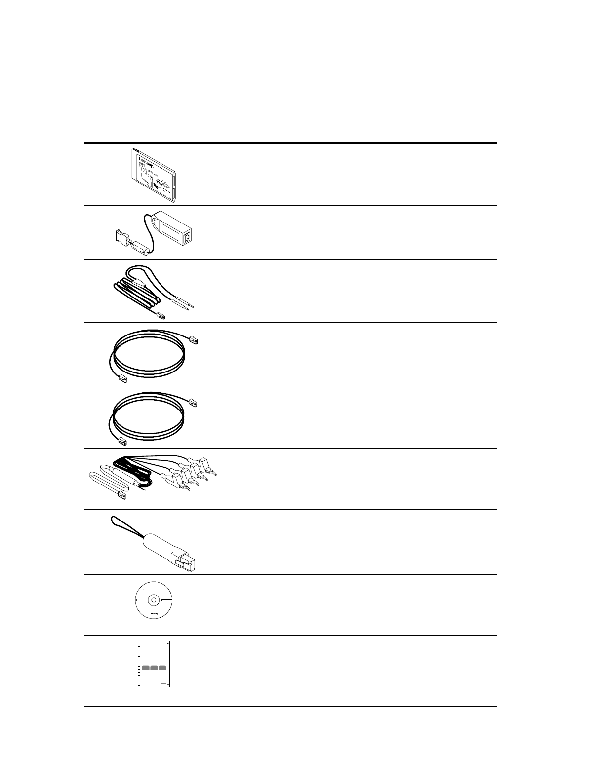
Table 1- 1: Components and accessories
YBT1 PC Card. Acts as the product platform and provides
a T1 digital interface to the Y350 NetTek Analyzer Platform.
See page B--1 for replacement information.
T1 Line Interface. Adapts the PC card interface to RJ48
test cables. See page B--1 for replacement information.
RJ48-to-Bantam Y Cable. Provides a RJ48-compatible
connection between the T1 Line Interface and a DSX patch
panel. See page B--1 for replacement information.
RJ48-to-RJ48 Straight-Wired Cable. Provides a
RJ48-compatible connection between the T1 Line Interface
and base station equipment. See the list of optional
accessories on page B--2 for ordering information.
RJ48-to-RJ48 Cross-Wired Cable. Provides a RJ48-compatible connection between the T1 Line Interface and the
base station NIU (Network Interface Unit). See the list of
optional accessories on page B--2 for ordering information.
RJ48-to-Alligator Clip Cable. Provides a connection
between the T1 Line Interface and the internal wiring of
base station equipment. See the list of optional accessories
on page B--2 for ordering information.
RJ48 Loopback Plug. Connects the NetTek YBT1 receive
input to the NetTek YBT1 transmit output w hen plugged into
the T1 Line Interface. Required to r un the diagnostic self
tests. See page B--1 for replacement information.
Installation Software CD-ROM. Installs NetTek YBT1
software on the Y350 NetTek Analyzer Platforms from a
desktop computer. See page B--1 for replacement
information.
User Manual. Provides setup and basic operating
information. (The CD-ROM is packaged inside the user
manual.) See page B--1 for replacement information.
1- 4
NetTek YBT1 T1 Circuit Tester User Manual
Page 21
Installing NetTek YBT1 Software
If you purchased a Y350 Net Tek Analyzer Platform and NetTek
YBT1 directly from Tektronix, the T1 Circuit Tester software is
already installed and the tester is ready to operate.
NetTek YBT1 Field Tool Software Purchased Separately
If you purchased NetTek BTS Field Tools previously and are adding
a NetTek YBT1 T1 Circuit Tester, follow the procedure on page D-- 1
to install the NetTek YBT1 software on the Y350 NetTek Analyzer
Platform.
Software Upgrades
To upgrade or reinstall NetTek YBT1 software on the Y350 NetTek
Analyzer Platform, follow the procedure on page D--1.
Getting Started
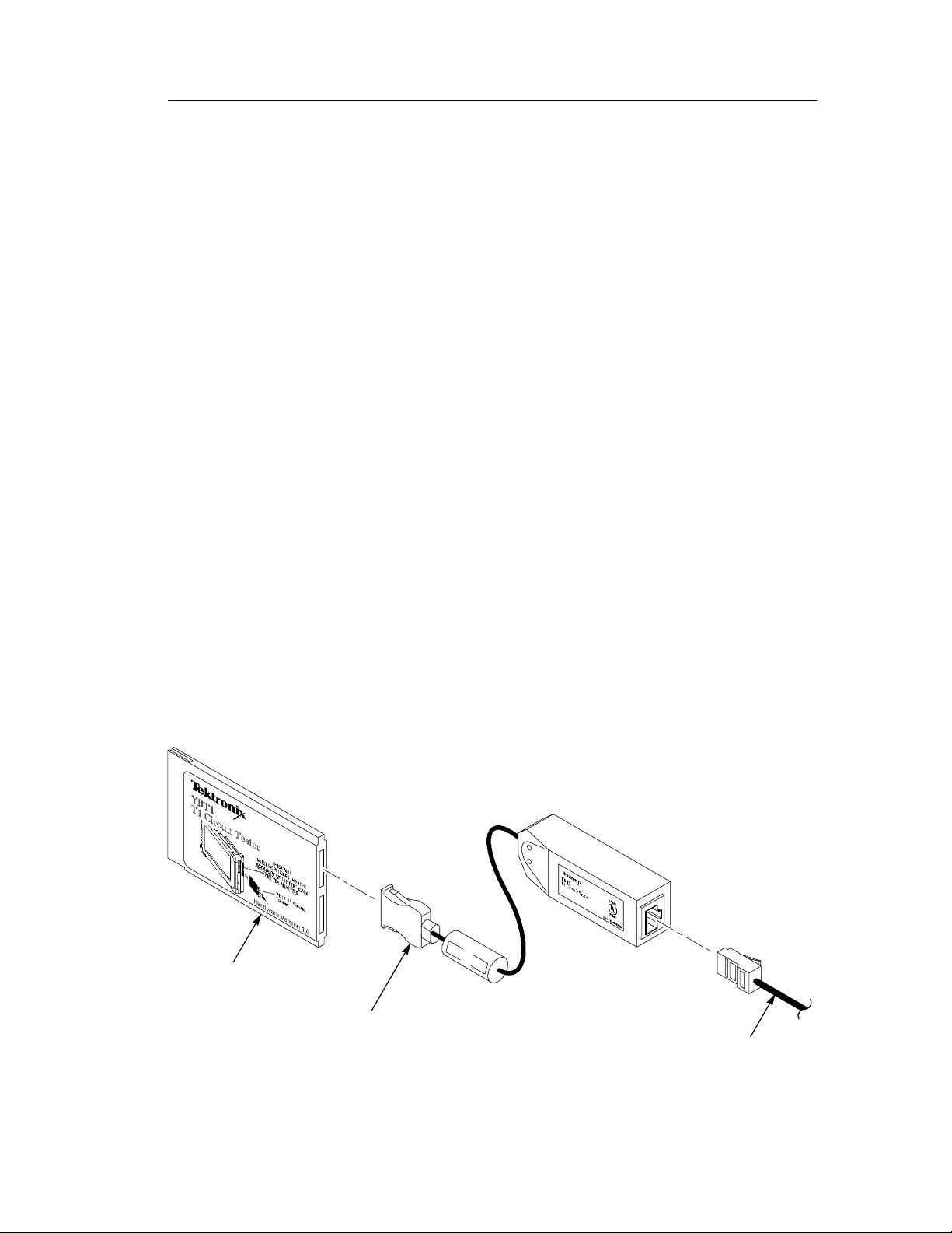
Assembling the PC Card and Line Interface
1. Connect the PC card to the T1 Line Interface. See Figure 1--2.
2. Connect the RJ48 cables best suited to your individual test needs
to the line interface.
YBT1 PC card
T1 Line Interface
RJ48 test cable
Figure 1- 2: Assembling the NetTek YBT1
NetTek YBT1 T1 Circuit Tester User Manual
1- 5
Page 22
Getting Started
Installing the PC Card
Use the following procedure to install the NetTek YBT1 PC card in
the Y350 NetTek Analyzer Platform.
CAUTION. To meet the electromagnetic emissions standards specified
for this product, install the NetTek YBT1 PC card in the rear slot of
the NetTek Analyzer Platform. See Figure 1--3.
In addition, do not install any other PC card while using the NetTek
YBT1 card.
1. Place the NetTek Analyzer Platform on a flat surface with the
touch-screen display facing towards you.
2. Open the PC card access door on the right side of the analyzer.
See Figure 1--3.
3. Slide the PC card into the rear PCMCIA slot as shown in
Figure 1--3. Make sure the Tektronix side of the label faces
toward the display.
4. Press in firmly to seat the PC card connector.
5. To release the card later, press the button at the top of the card
slot.
1- 6
NetTek YBT1 T1 Circuit Tester User Manual
Page 23
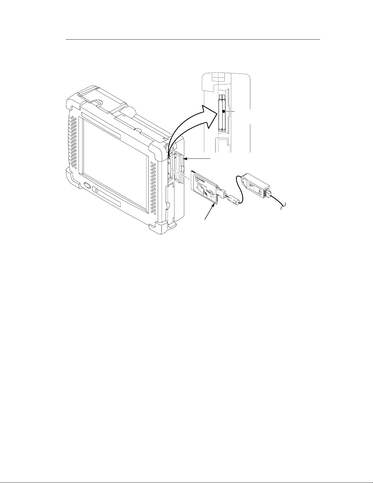
Install the NetTek YBT1 PC
card in this slot.
Access door
Getting Started
Figure 1- 3: Installing the PC card
YBT1 PC card
NetTek YBT1 T1 Circuit Tester User Manual
1- 7
Page 24
Getting Started
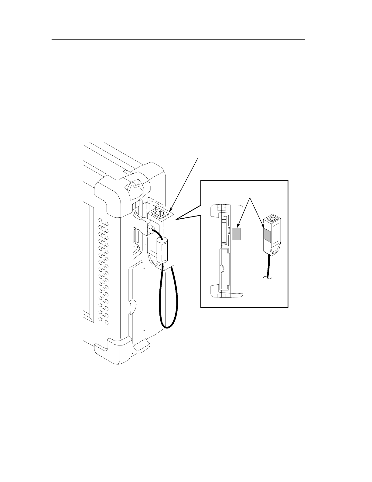
Securing the Cables
To prevent damage to the PC card and T1 line interface connections
by overextending the cables, you may want to secure the line
interface to the side of the Y350 NetTek Analyzer Platform with the
included Velcro strips. See Figure 1--4.
Secure the line interface to the side of the
Y350 analyzer with Velcro strips.
Attach Velcro here.
1- 8
Figure 1- 4: Attaching the line interface to the Y350 NetTek Analyzer
Platform
NetTek YBT1 T1 Circuit Tester User Manual
Page 25

Powering On the Tester
Press the large blue oval button in the lower-left corner of the Y350
NetTek Analyzer Platform. The power status indicator illuminates
immediately. Allow approximately one minute for the analyzer
platform to complete the power-on sequence.
Starting the NetTek YBT1 Software
You have the following options to start up the NetTek YBT1
measurement software:
H Double-tap the YBT1 application icon on the NetTek Analyzer
Platform desktop if present. The shortcut icon must be previously
created by the user or set up at the factory.
Getting Started
H Select Start > Programs > NetTek > YBT1 in the taskbar.
H Depending on the configuration of your NetTek Analyzer
Platform, the NetTek YBT1 software can start up automatically
at power on.
Configure the NetTek YBT1 to Start Up Automatically
Use the following procedure to configure the NetTek Analyzer
Platform to start up the NetTek YBT1 software at power on.
1. Select Start > Programs > Windows Explorer.
2. Navigate to the Windows\Programs\NetTek directory.
3. Select YBT1 (Shortcut) in the NetTek directory.
4. In the menu bar, select Edit > Copy.
5. Navigate back to the \Windows directory by tapping the left
arrow in the menu bar.
6. Open the Startup folder.
7. In the menu bar, select Edit > Paste Shortcut.
NetTek YBT1 T1 Circuit Tester User Manual
1- 9
Page 26
Getting Started
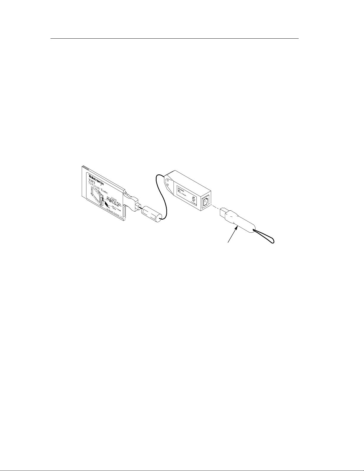
Performing a Functional Check
Following installation and start up of the NetTek YBT1 software,
perform the following procedure to verify that the T1 Circuit Tester
is functioning properly.
1. Insert the RJ48 Loopback Plug into the T1 Line Interface as
shown in Figure 1--5.
2. Perform the diagnostic tests on page C--1.
Figure 1- 5: Inserting the Loopback Plug into the T1 Line Interface
Powering Off the Tester
The NetTek YBT1 has separate, interrelated, standby and power off
functions.
Suspend Mode
Use Suspend mode to place the NetTek YBT1 in a suspended
(standby/sleep) state. This is the typical power down mode that
allows the NetTek YBT1 software to remain in volatile memory. If
the NetTek YBT1 remains in Suspend mode for an extended time
(approximately two hours), it will automatically enter Shutdown
mode.
Loopback plug
1- 10
NetTek YBT1 T1 Circuit Tester User Manual
Page 27

Getting Started
To suspend NetTek YBT1 operations, choose one of the following
methods:
H Press the front-panel power switch.
H Select Start > Shutdown. In the Shut Down dialog box, select
Suspend.
To cancel Suspend mode and wake up the NetTek YBT1, press the
front-panel power switch. The NetTek YBT1 will return to the
operating state that existed before suspend mode was invoked.
Shutdown
To completely power down the NetTek YBT1, do the following:
1. Select Start > Shutdown.
2. In the Shut Down dialog box, select Shutdown.
The next time you press the front-panel power switch, the NetTek
YBT1 will cycle through the complete power up process, which
takes approximately two to three minutes.
Restart (Software Reset)
To reset the NetTek YBT1 software:
1. Select Start > Shutdown.
2. In the Shut Down dialog box, select Restart.
The display blanks for approximately five seconds. The NetTek
YBT1 software will reload and start up.
Understanding the Power Switch
Depending on the current state of the NetTek YBT1, pressing the
front-panel power switch performs one of the following functions:
H If the NetTek YBT1 is shut down: powers on the instrument.
H If the NetTek YBT1 is operating: initiates Suspend mode.
H If the NetTek YBT1 is in Suspend mode: cancels Suspend mode
and activates the NetTek YBT1.
NetTek YBT1 T1 Circuit Tester User Manual
1- 11
Page 28

Getting Started
H If the NetTek YBT1 is in PowerSaver mode (touch-screen display
off): activates the display.
Preventing Personal Injury from the Effects of Lightning
WARNING. To prevent personal injury from the effects of lightning,
exercise the following precautions when using this product.
Before connecting this product to any source
H Be sure there is no lightning in your vicinity.
H Check your local weather forecast for the possibility of
thunderstorms or lightning.
H If weather conditions could allow thunderstorms or lightning to
develop, be sure to visually check the sky and weather conditions
in your area frequently.
H If you hear thunder or see lightning, do not connect this product
to any source that may be exposed to the effects of lightning.
H Use your own good judgement and common sense. You must
protect yourself from the effects of lightning.
H You must assume that hazardous voltages will be present on
exposed surfaces of this product if it is connected to a source
exposed to lightning. The insulation of this product will not
protect you from these hazardous voltages.
Do not connect this product to any source that might be subject to the
effects of lightning
If thunderstorms or lightning are in your vicinity:
H When weather conditions that could lead to lightning activity
exist in your area, you could be at risk of a lightning strike
before the cloud is close enough for you to hear thunder or see
lightning.
1- 12
NetTek YBT1 T1 Circuit Tester User Manual
Page 29

Getting Started
H When lightning strikes a structure or facility, current travels
through the rebar, concrete, pipes, cables, vent stacks, and
electrical system.
H Lightning can induce electric and magnetic fields into structures
and portions of wiring. The length of a conductor affected by the
magnetic field of a lightning strike may exceed two miles.
Be alert and aware of the effects of l ightning
H When lightning strikes a conductor, which in turn introduces
current into an area some distance from the ground strike point,
equipment can be damaged and personnel injured if they
become an indirect path in the completion of the ground circuit.
H Conductors such as the braided shields of cables or unshielded
wire, will have significant transient currents flowing in them in
regions exposed to the electric field effect of lightning.
H Induced voltages may cause breakdown of insulation in wiring at
connectors and in electrical components, or breakdown of air.
NetTek YBT1 T1 Circuit Tester User Manual
1- 13
Page 30

Getting Started
1- 14
NetTek YBT1 T1 Circuit Tester User Manual
Page 31

Operating Basics
Page 32

Page 33

Operating Basics
This section provides the information you need to operate the
NetTek YBT1 T1 Circuit Tester:
H Identifying the front-panel controls
H Navigating the desktop
H Entering text with the soft keyboard
H Getting help
H Understanding the test windows
Overview
The NetTek YBT1 is a member of the Tektronix NetTek Series of
modular instruments. A NetTek Series instrument consists of a
hardware module, application software, and the Y350 NetTek
Analyzer Platform. NetTek Series instruments can be purchased with
or without the NetTek Analyzer Platform.
The NetTek Analyzer Platform consists of a specialized Windows
CE-based computer and display. It is also the power source for all
NetTek Series hardware modules. The hardware module for each
instrument consists of analysis circuitry that works in conjunction
with application-specific software, which provides the instrume nt
interface and analysis capability.
The NetTek YBT1 is equipped with a touch-screen display and
stylus. Use the stylus as you would the mouse on your desktop
computer. You can select an object by tapping it, move it by
dragging it, or activating it by double-tapping it.
CAUTION. Only use soft objects, such as plastic or your finger, to tap
the touch-screen display. Do not use metal or other abrasive
materials as they will damage the display surface.
NetTek YBT1 T1 Circuit Tester User Manual
2- 1
Page 34

Operating Basics
Identifying Front-Panel Controls and Indicators
The front-panel controls power the NetTek Analyzer Platform on and
off, reset the analyzer, and indicate operating status.
2- 2
123 4
Figure 2- 1: NetTek Analyzer Platform front-panel controls and
indicators
1.
Power/Suspend Switch. Push on; push off. See pages 1--9 and
1--10 for additional information.
2.
Reset Switch. Push to perform a hardware reset if the tester
locks up. Programs and other data loaded into volatile memory
since startup will be lost.
NetTek YBT1 T1 Circuit Tester User Manual
Page 35

3.
Status Indicator. Green indicates power on. Amber indicates
display off PowerSaver mode.
4.
Batteries Indicator.
to an external power source and charging a battery, if installed.
Red indicates a low battery.
Navigating the Desktop
The NetTek Analyzer Platform desktop is your primary workplace.
Use the desktop to configure hardware and software, adjust settings,
establish communications, and access application software.
Operating Basics
Green indicates the instrument is connected
Desktop
Icon
Taskbar
Figure 2- 2: NetTek Analyzer Platform desktop
NetTek YBT1 T1 Circuit Tester User Manual
2- 3
Page 36

Operating Basics
Icons
Double-tap on desktop icons to open folders or to start programs.
Taskbar
The Taskbar contains the Start menu, buttons to minimize the
programs you are running, a status area, and a return to desktop
button.
Start menu
Program button Status area
Start Menu. Use the Start menu to load and run instrument modules
Desktop button
and other programs, access settings, open documents, and obtain
help. Select (tap) Start to open the menu; then select the entry you
want.
For detailed information on Start menu selections, see the Y350
NetTek Analyzer Platform User Manual.
2- 4
Select Start to open
Desktop Button. Tap the desktop button to minimize all running
programs and display the desktop.
NetTek YBT1 T1 Circuit Tester User Manual
Page 37

Operating Basics
Program Buttons. To minimize a program that is running, select its
taskbar button. To restore the program, select the button again.
Status Area. Icons and buttons appearing in this area indicate status,
activate features, or open settings windows. Double-tap the icons for
further information.
Table 2--1 explains the function of some common status icons. For a
complete list and explanation of all status area icons, refer to the
NetTek Analyzer Platform online help. Select Start > Help.Inthe
help window select Windows CE Basics; then select Understanding
Taskbar Icons.
Table2-1:Statusareaicons
Tap icon To Details
Double-tap to open the Power
Management utility.
Double-tap to open the Power
Management utility.
Double-tap to open the Power
Management utility.
Double-tap to open the Backlight
utility.
Single-tap to open the Input
Panel soft keyboard.
Double-tap to open the Date/Time
utility.
The analyzer is operating
on external AC power.
The analyzer is charging
batteries.
The analyzer is operating
on battery power. Also
indicates charge level.
Adjust the backlight brightness.
Single-taptoclosethe
keyboard.
Set the date and time.
NetTek YBT1 T1 Circuit Tester User Manual
2- 5
Page 38

Operating Basics
Entering Text
Use the NetTek Analyzer Platform soft keyboard to type characters
into text boxes or address fields without using an external keyboard.
Figure 2- 3: Soft keyboard
1. Tap the
2. Tap the Input Panel keys to enter text.
3. Tap
4. Tap the keyboard icon to close the keyboard.
To set soft keyboard properties, sel ect Start > Setti ngs > Control
Panel. Open the Input Panel icon, and then select Options.
Special Characters
The soft keyboard includes characters not visible on the startup
keyboard.
CAP Key. Tap the CAP (lock) key to create all capital letters and
common characters.
Shift Key. Tap the Shift key to create a single capital letter or
common character.
icon in the toolbar status area.
(RETURN) to wrap text or execute a command.
2- 6
AU Key. Tap the key to create special characters.
NetTek YBT1 T1 Circuit Tester User Manual
Page 39

Getting Help
To open the Help Contents menu on the Y350 NetTek Analyzer
Platform, select Start > Help in the Taskbar.
To open the Help window and obtain information on T1 Circuit
Tester topics, select Help from the Start menu; then select ybt1.
Use the following methods to obtain help while running the T1
Circuit Tester:
Operating Basics
H Tap the
icon in the upper-right corner of the touch screen to
display the top level of NetTek YBT1 help.
H Tap underlined text to display information on a specific topic.
H Tap the Help button in a dialog box, if present, to display
task-specific information.
The Help Window
Table 2--2 explains how to use the Help window buttons.
Table 2- 2: Help window buttons
Tap this button To
All Topics Display the NetTek Analyzer Platform main table of
contents.
Back Return to the previous help screen.
Contents Display the current program or local table of contents.
Display full-screen help text.
Display the help text in its own window. Tap and drag
the Help window title bar to move the window.
Close the Help window. To reopen, tap the Help icon
in the taskbar.
Close the Help window and quit help.
NetTek YBT1 T1 Circuit Tester User Manual
2- 7
Page 40

Operating Basics
Table 2- 2: Help window buttons (Cont.)
Tap this button To
Using the Main Controls
Figure 2--4 shows the basic controls available in the test windows.
Scroll the text towards the bottom of the screen.
Scroll the text towards the top of the screen.
2- 8
Figure 2- 4: NetTek YBT1 main controls
NetTek YBT1 T1 Circuit Tester User Manual
Page 41

Operating Basics
Menus
Table 2-- 3 lists the available menu selections.
Table 2- 3: NetTek YBT1 menu selections
Menu Function or description
File >
Open Invokes the Open dialog box to select and open a
previously saved *.nr0 results file.
Open Last Results Recalls the results of the previous test, or data
collected since the last Restart.
Save Results Saves the results of the current test. Uses identical
settings as the previous Save Results As and
Settings > Save and Export dialog boxes.
Save Results As Saves the current test results as specified by the
Save As and Settings > Save and Export dialog
boxes.
Export Results As Invokes the Save As dialog box to save results as a
tab-separated or comma-separated file for export by
the NetTek Analyzer Platform.
Export Screen As Invokes the Save As dialog box to save screens as
PNG, JPEG, or Bitmap files for export by the NetTek
Analyzer Platform.
Print Invokes the Print dialog box to print the current
screen.
Results Properties Lists the Settings > Save and Export properties and
user notes to be saved with the current results file.
Exit Closes the NetTek YBT1 application.
NetTek YBT1 T1 Circuit Tester User Manual
2- 9
Page 42

Operating Basics
Table 2- 3: NetTek YBT1 menu selections (Cont.)
Menu Function or description
Setup >
Edit Invokes the Settings dialog box to change or
Open Invokes the Open dialog box to execute *.sav files for
Save Invokes the Save As dialog box to save current
Preset Returns the NetTek YBT1 to factory default settings.
Tools >
configure instrument settings.
changing instrument settings.
instrument settings as a *.sav file.
Options Opens the Setup Menu dialog box to show/hide and
protect instrument settings.
Keyboard Invokes the on-screen soft keyboard to enter
alphanumeric characters into entry fields and dialog
boxes.
Touchscreen
Calibration
Upgrade Software See Appendix D for software upgrade instructions.
Technical Support Displays information on how to contact Tektronix.
Software Info Displays the NetTek YBT1 software version and other
Hardware Info Displays NetTek YBT1 hardware properties.
Invokes the Stylus Properties dialog box for
calibrating the touch-screen display.
properties.
2- 10
NetTek YBT1 T1 Circuit Tester User Manual
Page 43

Operating Basics
Toolbar Buttons
Table 2--4 shows the toolbar buttons and explains their function.
Table 2- 4: Toolbar icons
Tap this icon To Details
Open the File menu Save or export results and
screens; exit the software.
Open the Setup menu Edit settings; access or
save user data; return to
factory default settings.
Open the Tools menu Configure option settings;
open the keyboard; calibrate the touch screen;
obtain hardware and software version information.
Save results (File > Save
Results)
Open instrument Settings
window (Setup > Edit)
Pause a test Allows viewing or capture
Resumeatest
Open the help window Obtain NetTek YBT1 help.
1
BuiltInDisk\YBT1\Results.
2
Data collection continues while screen is paused.
Save current results to
default file location.
1
Configure instrument settings. See page 3--9.
of results screens.
2
NetTek YBT1 T1 Circuit Tester User Manual
2- 11
Page 44

Operating Basics
Configuration Buttons
Select an option button for the type of circuit connection you want to
make. For detailed information on connecting the NetTek YBT1 to a
signal, see page 3--1.
impedance and compensates for the 20 dB resistive loss of a DSX
monitor port. This configuration is useful for in-service monitoring
of T1 lines at DSX monitor ports that are resistor-isolated.
The YBT1 transmitter is disabled in Monitor configuration.
impedance for bridging lines that are already terminated and
compensates for cable losses of up to 10 dB.
The YBT1 transmitter is disabled in Bridge configuration.
Monitor. Selecting Monitor provides a nominal 100 Ω input
Bridge. Selecting Bridge provides greater than 1 kΩ input
Terminate. Selecting Terminate provides a nominal 100 Ω
input impedance and compensates for up to 10 dB of cable loss for
T1 lines.
This configuration enables the NetTek YBT1 transmitter for error
insertion, which is useful for out-of-service testing when you can
terminate the line.
Loopback. Selecting Loopback provides a nominal 100 Ω
input impedance and compensates for up to 10 dB of cable loss in T1
lines.
Use this configuration to take measurements on received data while
looping the payload data from the receiver back to the transmitter.
Loopback is useful when testing from the far end of a T1 line.
Loop Far End. Selecting the Loop Up button initiates
transmission of the loop code specified in the Settings Dialog Box
Loop Codes tab (Setup > Edit > Loop Codes). This configuration is
the result of the NetTek YBT1 sending a loop code and successfully
completing a loop back of equipment at the far end. For additional
information, see Loop Codes Button on page 2--13.
2- 12
NetTek YBT1 test functionality using a far end loop is identical to
that of Terminate c onfiguration.
NetTek YBT1 T1 Circuit Tester User Manual
Page 45

Operating Basics
Select the Loop Down button to remove the far end loop and return
the NetTek YBT1 to Terminate configuration.
NOTE. You must use Terminate configuration to activate the Loop Up
button.
Loop Codes Button
Select this button to open the Settings Dialog Box Loop Codes tab
(Setup > Edit > Loop Codes). Use this dialog box to setup a loop
code.
The ANSI T1 standard defines the following loop control formats:
H In-Band Codes: transmitted in place of payload data (without
framing bits). These codes are repeat ed continuously for a peri od
of 5 seconds and are defined for use with either D4 (Superframe)
or ESF framing formats.
H Out-of-Band Codes: defined for ESF framing only. An out-of-
band communication link does not exist for D4 framing.
Additionally, there are two types of loop codes:
H Line Loopback: generates a full 1.5444 Mbps stream looping
back from the receiver to the transmitter, including the framing
bits.
H Payload Loopback: the equipment performing the loopback
generates the framing, looping back 1.536 Mbps user channel
data only.
The YBT1 Tester uses line loopback codes only.
1. Select the appropriate option button to specify a loop code:
H CSU: select a loop code in the drop-down menu.
H NIU: select a loop code in the drop-down menu.
H User: tap the keypad icon to open the numeric keypad; then
tap the left and right arrows to enter a binary code.
2. Tap OK.
NetTek YBT1 T1 Circuit Tester User Manual
2- 13
Page 46

Operating Basics
The current loop code is displayed below the Loop Up / Loop Down
button.
Loop Up Button
Select this button to send a loop code and loop up e quipment at the
far end. For additional information, see Loop Far End on page 2--12.
The current loop code is displayed below the Loop Up / Loop Down
button.
Loop Down Button
Select this button to remove the far end loop and return the NetTek
YBT1 to Terminate configuration. For additional information, see
Loop Far End on page 2--12.
Tx Setup Button
Select this button to open the Settings Dialog Box Instrument tab
(Setup > Edit > Instrument) and configure the NetTek YBT1
transmitter test parameters.
1. Select from the option buttons to configure the Line Coding,
Framing, and Transmit Clock settings.
2. Select from the option buttons to set the Transmit Level (output)
for a Terminate test configuration.
3. Select a Bit Error Rate (BER) test pattern from the drop--down
list box.
4. Tap OK.
The settings you enter become the active settings. They also are used
as the default settings at the next power up. The current NetTek
YBT1 transmitter settings are displayed below the Tx Setup button.
NOTE. Changing the test parameters automatically restarts the alarm
and error counters.
2- 14
NetTek YBT1 T1 Circuit Tester User Manual
Page 47

Operating Basics
Restart Button
Select this button to reset all of the current measurement status and
history, including error and alarm counts. If any instrument setting is
configured for “Same as Rx Signal”, a Restart will initiate the
receiver detection algorithm for the selected setting(s).
Rx Level Button
The NetTek YBT1 continuously monitors the received signal level
strength. Select this button to open the Receive Level window and
display the signal level strength in dBdsx and Volts peak-to-peak.
Line Code Button
The NetTek YBT1 continuously monitors the received signal to
determine the line coding. Select this button to open the Line Code
Detect window and display the line code currently being received.
The History field displays the number of seconds the indicated line
code has been received since the measurement began.
NOTE. The Line coding setting in the Setup > Edit > Instrument tab
must match the line code of the signal you are testing. You may need
to manually set the Line coding before taking measurements.
NOTE. Some received data patterns do not allow accurate detection
of line coding. In such cases, the NetTek YBT1 will report AMI line
coding. For meaningful detection to occur, the received data must
have sufficiently low ones density (or long enough strings of zeros) to
induce B8ZS substitutions.
Drop DS0 Button
Select this button to open the DS0 Activity Graph. This view
displays the data activity for each of the T1 time slots. Activity is
indicated as percentage ones-density in each time slot, represented as
NetTek YBT1 T1 Circuit Tester User Manual
2- 15
Page 48

Operating Basics
a unique color ranging from all zeros through all ones in 10%
increments.
Each row of the display represents a user-defined period of time.
Over multiple time periods, the display builds up row-by-row with
the oldest row dropping from the top of the view as the newest row is
added to the bottom.
To monitor audio data on a selected channel, do the following:
1. Tap the DS0 channel at the bottom of the displa y, 1 through 24.
2. Set the the speaker option button to on.
3. Tap and drag the slider to control the speaker volume.
Timed Test Button
Select this button to open open the Timed Test window. Use this
window to define the length of time to run a controlled test.
Auto Test Button
Select this button to open the Bert Pattern Selection dialog box. Use
this dialog box to select and run a preset or custom BER test pattern
sequence. See page 3--15 for additional information.
Open Last Results
If you accidentally pressed Restart or lost data while updating the
display time span, select File > Open Last Results. This comma nd
returns the results of the previous test, or data collected since the last
Restart. You can use most of the controls to analyze the logged data.
NOTE. If you accidentally lost data by selecting the wrong control,
select File > Open Last Results to return the results of the previous
test.
2- 16
Summary Tab
Select this tab to open the Summary window. See page 2--19 for
detailed information.
NetTek YBT1 T1 Circuit Tester User Manual
Page 49

Operating Basics
Alarms Tab
Select this tab to open the Alarms window. See page 2--20 for
detailed information.
Errors Tab
Select this tab to open the Errors window. See page 2--23 for detailed
information.
History Tab
Select this tab to open the Test History window. See page 2--26 for
detailed information.
Rx Status Indicator
This indicator identifies valid T1 pulses at the NetTek YBT1
Receive input.
H Green indicates that T1 pulses have been detected.
H White indicates that the NetTek YBT1 is searching for T1 pulses.
During the search the T1 pulse indicator displays Receiving.Ifthe
NetTek YBT1 detects T1 pulses at a level too low to make accurate
measurements, it displays Weak Signal and continues searching.
Frame Sync Indicator
The NetTek YBT1 compares the data framing detected at the
Receive input to the criteria selected in the Settings Dialog Box
Instrument tab (Setup > Edit > Instrument).
H Green indicates that the received framing matches the instrument
settings.
H Red indicates that the received framing does not match t he
instrument settings.
H White indicates that the NetTek YBT1 is searching for framing
synchronization.
The Frame Sync Indicator displays the type of framing detected: D4
or ESF. During the search the indicator displays Receiving.
NetTek YBT1 T1 Circuit Tester User Manual
2- 17
Page 50

Operating Basics
Pattern Sync Indicator
The NetTek YBT1 compares the data pattern at the Receive input to
the BER pattern selected in the Settings Dialog Box Instrument tab
(Setup > Edit > Instrument).
H Green indicates that the received data pattern matches the
instrument settings.
H Red indicates that the received data pattern does not match the
instrument settings.
H White indicates that the NetTek YBT1 is searching for pattern
synchronization.
The Pattern Sync Indicator displays the type of pattern detected if
known: QRSS, ALL Ones, All Zeros, 1in8... During the search the
indicator displays Receiving.
If a known pattern is not detected for a period exceeding 10 seconds,
the indicator displays Unknown. Unknown is also a likely pattern
detected for live lines.
Instrument Settings
For information on how to modify the NetTek YBT1 instrument
settings, such as line coding, framing, transmitter clock, BER test
patterns, and transmitter output level, or how to perform specialized
testing on T1 circuits, see page 3--9.
2- 18
NetTek YBT1 T1 Circuit Tester User Manual
Page 51

Understanding the Summary Window
This is the default test window. The Summary window reports the
accumulated test results since the last time you began a test or
selected the Restart button. View this window to obtain general
information before navigating to other windows for detailed results.
To open this window, select the Summary tab on the left side of the
display.
Operating Basics
Figure 2- 5: NetTek YBT1 Summary window
T1 Circuit Test Summary
This field summarizes the current test results.
OK. Indicates that no alarms or errors were detected during the test
period or since the last Restart.
NetTek YBT1 T1 Circuit Tester User Manual
2- 19
Page 52

Operating Basics
Alarm /Error Type. Lists the type of alarm or e rror detected during the
test period.
Total Alarm Time. Lists the time duration of the alarm.
Total Error Count. Lists details specific to the detected error(s).
Understanding the Alarms Window
This window reports alarm events collected during the test period.
View this window to obtain alarms event history from the Alarms
Rolling Display. To open to this window, select the Alarms tab on
the left side of the display.
2- 20
History button Event detail Event indicator
Figure 2- 6: NetTek YBT1 Alarms window
NetTek YBT1 T1 Circuit Tester User Manual
Page 53

Operating Basics
Alarms Rolling Display
The Alarms Rolling Display scrolls from right to left to document
alarm events in time.
Event Indicator
An event indicator marks the occurrence of an alarm event. Each
indicator represents the time period specified by the data collection
resolution.
To view details of an event, tap on an event indicator. The indicator
changes color from red to yellow following your tap. Details of the
event appear in the Event Detail field at the bottom of the display.
History Indicator
On the left side of the rolling display, a red History indicator denotes
that historical information is available for the alarm type indicated; a
white history indicator denotes that no historical information is
available.
Select the History tab to view accumulated alarm details for the last
150 time intervals or the number of alarms detected since the
beginning of the test.
Current Indicator
Red indicates this alarm type is currently being detected; white
indicates that this alarm type is not being detected.
Display Time Span
To set the collection resolution and data collection time of the
Alarms Rolling Display, do the following:
1. Tap the Updates button in the Alarms window (Setup > Edit >
Data Collection).
2. Select a Time Interval (data collection time) from the drop--down
list box.
3. Tap OK.
The 30 most recent time intervals comprise the default display time
span of the rolling display. You can scroll beyond the 30 most recent
events by tapping and dragging the scroll bar. Select the History tab
NetTek YBT1 T1 Circuit Tester User Manual
2- 21
Page 54

Operating Basics
to review details of the last 150 time intervals or the number of
errors detected since the beginning of the test.
Updated settings become the active settings. They will also be used
as the default settings at the next power up.
NOTE. Updating the time interval restarts the test. Data collected for
the current test is deleted from memory.
Event Detail
Tap on an event indicator in the rolling display to list the time, date,
and number of alarms detected within the time interval represented
by the selected event indicator. Information is displayed in the Event
Detail field at the bottom of the window.
Tap the left and right arrows to scroll through the time record for
information on each event.
2- 22
NetTek YBT1 T1 Circuit Tester User Manual
Page 55

Understanding the Errors Window
This window reports error events collected during the test period.
View this window to obtain errors event history from t he E rrors
Rolling Display. To open this window, select the Errors tabonthe
left side of the display.
Operating Basics
Event detail Event indicatorHistory button
Figure 2- 7: NetTek YBT1 Errors window
Errors Rolling Display
The Errors Rolling Display scrolls from right to left to document
error events in time.
NetTek YBT1 T1 Circuit Tester User Manual
2- 23
Page 56

Operating Basics
Event Indicator
An event indicator marks the occurrence of an error event. Each
indicator represents the time period specified by the data collection
resolution.
To view details of an event, tap on an event indicator. The indicator
changes color from red to yellow following your tap. Details of the
event appear in the Event Detail field at the bottom of the display.
History Indicator
On the left side of the rolling display, a red History indicator denotes
that historical information is available for the error type indicated; a
white history indicator denotes that no historical information i s
available.
Select the History tab to view accumulated error details for the last
150 time intervals or the number of alarms detected since the
beginning of the test.
Current Indicator
Red indicates that this Error Type is currently being de tected.
Display Timespan
To set the collection resolution and data collection time of the Errors
Rolling Display, do the following:
1. Tap the Updates button in the Errors window (Setup > Edit >
Data Collection).
2. Select a Time Interval (data collection time) from the drop--down
list box.
3. Tap OK.
The 30 most recent time intervals comprise the default display time
span of the rolling display. You can scroll beyond the 30 most recent
events by tapping and dragging the scroll bar. Select the History tab
to review details of the last 150 time intervals or the number of
errors detected since the beginning of the test.
Updated settings become the active settings. They will also be used
as the default settings at the next power up.
2- 24
NetTek YBT1 T1 Circuit Tester User Manual
Page 57

Operating Basics
NOTE. Updating the time interval restarts the test. Data collected for
the current test is deleted from memory.
Event Detail
Tap on an event indicator in the rolling display to list the time, date,
and number of alarms detected within the time interval represented
by the selected event indicator. Information is displayed in the Event
Detail field at the bottom of the window.
Tap the left and right arrows to scroll through the time record for
information on each event.
BER Count
The BER: indicator (bit error rate indicator) displays the cum ulative
bit error rate since the last time you began a test or selected the
Restart button. The reported BER is calculated for the total number
of bits received for a synchronized pattern session.
Error Insertion List Box
To insert a single error into the NetTek YBT1 output data stream:
1. Configure the NetTek YBT1 for a Terminate connect ion. See
page 3--4 for instructions.
2. Select an error type from the Insert Error drop-down list box.
3. Tap the Insert Error button.
The NetTek YBT1 transmits a single error immediately. You must
loop the far end connection to monitor errors at the Rx (Receive)
input of the NetTek YBT1. See Loop Far End on page 2--12 for
further details.
NetTek YBT1 T1 Circuit Tester User Manual
2- 25
Page 58

Operating Basics
Understanding the History Window
The History window lists test results since the last time you began a
test or selected the Restart button.
View this window for detailed information on the last 150 alarms
and errors, including the alarm/error type, number of o ccurrences
(count), and the time of each occurrence.
You can sort the information in this window by alarms/errors type,
count (in descending order), and time of occurrence by tapping the
appropriate column header.
To open this window, select the History tab on the left side of the
display.
2- 26
Figure 2- 8: NetTek YBT1 History window
NetTek YBT1 T1 Circuit Tester User Manual
Page 59

Reference
Page 60

Page 61

Connecting to a Signal
There are several ways to connect the NetTek YBT1 to a T1 circuit
within the base station environment. Each type of connection allows
you to test a different aspect of functionality.
DSX1panel
Base station
equipment
Tx Tx
Rx
Channel
Service
Figure 3- 1: Typical base station showing T1 network interfaces
Making a Monitor Connection
This is the most common type of connection to a DSX service panel.
With this configuration, you can use the YBT1 to monitor either the
network side or the customer side of the data stream, without
removing the line from service. This configuration does not transmit
data, therefore it does not block communications on either side.
Unit
DSX2panel
Rx
Wireless
operator
Network
Interface
Unit
Telco
Demarcation
Use this configuration to detect errors on the line, such as Bipolar
Violations (BPV) and CRC (Cyclic Redundancy Check) errors, or to
perform bit error-rate testing if a known test pattern is being
received.
NetTek YBT1 T1 Circuit Tester User Manual
3- 1
Page 62

Connecting to a Signal
As a typical example, to monitor an outgoing signa l at a DSX
service panel, configure the NetTek YBT1 as follows:
1. Connect the RJ48-to-Bantam Y Cable to the T1 Line Interfac e.
Seepage1--5.
2. Select the Monitor option button in the NetTek YBT1 Configu-
ration field.
3. Connect the Bantam “Receive” plug to the monitor jack on the
1
DSX
service panel as shown in Figure 3--2.
4. Select the Summary tabontheNetTekYBT1.
5. Press Restart to clear any alarm/error counts and begin the test.
1
DSX
MON
OUT
From CSU
To base station
MON
OUT
IN IN
Figure 3- 2: Typical connection for single-port monitoring
3- 2
NetTek YBT1 T1 Circuit Tester User Manual
Page 63

Making a Bridge Connection
Use this type of connection to perform nonintrusive testing on a T1
circuit, without being limited to a designated monitoring port with
the appropriate isolation.
Use this configuration to detect errors online, such as bipolar
violations and CRC errors, or to perform bit error-rate testing if a
known test pattern is being received.
For example, to connect the NetTek YBT1 to a T1 circuit without
loading the circuit, do the following:
Connecting to a Signal
1. Connect the
Seepage1--5.
2. Select the Bridge option button in the NetTek YBT1 Configura-
tion field.
3. Connect the “Receive” alligator clips to the appropriate points in
the service access. See Figure 3-- 3.
4. Select the Summary tabontheNetTekYBT1.
5. Press Restart to clear any alarm/error counts and begin the test.
RJ48-to-Alligator Clip Cable to the T1 Line Interface.
NetTek YBT1 T1 Circuit Tester User Manual
3- 3
Page 64

Connecting to a Signal
66 Block
RJ48- Alligator
clip cable
Figure 3- 3: Typical connections for bridge monitoring
Making a Terminate Connection
Use this type of connection to place the NetTek YBT1 at the end of a
service line when the line is out of service. With this configuration
you can test base station equipment independent of the service line,
or the service line independent of the base station.
For example, to test CSU equipment off line, connect the NetTek
YBT1 as follows:
Spade lug
3- 4
1. Connect the RJ48-to-Bantam Y to the T1 Line Interface. See
page 1--5.
NetTek YBT1 T1 Circuit Tester User Manual
Page 65

Connecting to a Signal
2. Select the Terminate option button in the NetTek YBT1
Configuration field.
3. Connect the “Transmit” Bantam plug to the IN side of the service
access as shown in Figure 3--4.
4. Connect the “Receive” Bantam plug to the OUT side of the
service access as shown in Figure 3-- 4.
5. Loop the DSX2service panel at the NIU.
6. Select the Summary tabontheNetTekYBT1.
7. Press Restart to clear any alarm/error counts and begin the test.
X
DSX
MON
OUT
IN
MON
OUT
IN
From CSU
To CSU
Figure 3- 4: Typical connections for terminating a T1 circuit
NetTek YBT1 T1 Circuit Tester User Manual
3- 5
Page 66

Connecting to a Signal
Making a Loopback Connection
Use this type of connection to retransmit the incoming signa l back to
the point of origin through the NetTek YBT1. Looping back is
virtually equivalent to hard wiring the receive side of the line to the
transmit side of the line while allowing the NetTek YBT1 to make
measurements on the received data.
For example, to loopback a T1 circuit through the NetTek YBT1, do
the following:
1. Connect the RJ48-to-Bantam Y or
RJ48-to-Alligator Clip Cable to
the T1 Line Interface. See page 1--5.
2. Select the Loopback option button in the NetTek YBT1
Configuration field.
3. Connect the “Transmit” Bantam plug or alligator clips to the IN
or OUT side of the service access, depending on the circuit you
want to terminate. Connect the “Receive” Bantam plug or
alligator clips to the other side of the line for monitoring
purposes. See Figure 3--5.
4. Select the Summary tabontheNetTekYBT1.
5. Press the Restart butt on to clear any previous alarm/error counts
and begin the test.
X
DSX
3- 6
MON
OUT
IN
MON
OUT
IN
From CSU
To CSU
Figure 3- 5: Typical connections for loopback mode
NetTek YBT1 T1 Circuit Tester User Manual
Page 67

Testing a Circuit
After you connect the NetTek YBT1 t o a signal, select the Restart
button to begin testing. To assure accurate measurements, verify that
there is sufficient receive signal level and that the line coding is
correct:
1. Select the Rx Level button on the right side of the display. Verify
that the signal level meets the minimum receiver sensitivity
requirements listed in the Specifications section. See page A--1.
2. Select the Line Code button on the right side of the display.
Verify that the expected line code is correct for the type of signal
you are testing. For information on how to set the line code, see
Selecting Settings beginning on page 3--9.
Typically, the first t hing you see in the main window (Summary tab)
is an indication that either the data stream contains no anomalies (the
display reads “OK”), or that the NetTek YBT1 detected an alarm or
error, in which case the T1 Circuit Test Summary results are
displayed. The T1 Circuit Test Summary lists all of the alarms or
errors detected since the last restart. See Figure 3--6.
Figure 3- 6: Summary window showing typical test results
NetTek YBT1 T1 Circuit Tester User Manual
3- 7
Page 68

Testing a Circuit
IftheNetTekYBT1detectedanalarmorerror,openanAlarmsor
Errors window to obtain additional information. (To open a window
select an Errors or Alarms tab.) These windows provide graphical
presentations of the most recent test events, as well as indicators that
show the current and past performance of the T1 line under test. To
view an itemized list of the alarm or error history since the last
restart, open the History tab.
You can also view all of the DS0 time slots simultaneously on the
Drop DS0 activity graph. A colored bar is displayed for each
consecutive time interval within the measurement time span. The
display is color coded to reveal common data problem patterns:
H Normally quiet channels may be disrupted by random noise.
H Channels normally containing variable data may be locked into a
continuous pattern.
H Normal startup protocol, represented by identifiable fixed bars,
may not change to a variable pattern.
You can also use the Drop DS0 feature for aural ide ntification of
some signal problems. For additional information, see page 3--13.
To view the DS0 Activity Graph, select the Drop DS0 button.
Measurement results accumulate as long as the NetTek YBT1 detects
T1 pulses. You can view test summary results at the end of a timed
test or while a test is running by selecting the History tab.
NOTE. To ensure accurate measurements, always press the Restart
button after you connect the NetTek YBT1 Tester t o a circuit.
3- 8
NetTek YBT1 T1 Circuit Tester User Manual
Page 69

Selecting Settings
The NetTek YBT1 automatically detects most of the parameters
necessary to test a T1 circuit. However, you can override any or all
of the automated set tings to speed up synchronization or to perform
specialized tests.
NOTE. The Line Coding setting in the Setup > Edit > Instrument tab
must match the line code of the signal you are testing. Select the
Line Code button on the right side of the display to view the line
code currently being detected. You may need to manually set the Line
Coding in the Instrument tab before taking measurements.
To set the NetTek YBT1 receive function for automated testing, do
the following:
Testing a Circuit
1. Select Setup > Edit in the toolbar at the top of the startup
window.
2. Open the Instrument tab and configure the option buttons as
follows:
a. Line Coding: AMI or B8ZS.
b. Framing: Same as Rx Signal.
c. Transmit Clock: Recovered.
d. Generated BER Pattern: Same as Rx Signal.
The NetTek YBT1 will automatically detect data formatting and
analyze the received signal. To view summarized test results, tap the
Summary tab and check the T1 Circuit Test Summary report. To
view details of specific test results, select the Alarms or Errors tabs.
Instrument Settings Window
The Instrument Settings dialog box allows you to configure the
NetTek YBT1 for specialized testing of T1 circuits.
1. Select Setup > Edit to open the dialog box; then open the
Instrument tab. See Figure 3--7.
NetTek YBT1 T1 Circuit Tester User Manual
3- 9
Page 70

Testing a Circuit
2. Select the option buttons appropriate to the tests you want to
make.
Figure 3- 7: Instrument settings dialog box
Line Coding. Select the line coding for the YBT1 transmitter and
receiver.
H AMI. The YBT1 receiver will not perform B8ZS decoding on
incoming data.
H B8ZS. The YBT1 receiver will perform B8ZS decoding on
incoming data.
Framing. Select the frame format of the YBT1 transmitter and
receiver.
H Same as Rx Signal. Automatically detects the incoming framing
format and configures the YBT1 receiver and transmitter to
match.
3- 10
NetTek YBT1 T1 Circuit Tester User Manual
Page 71

Testing a Circuit
H D4. Configures the YBT1 to transmit and receive T1 data with
D4 (SuperFrame) framing.
H ESF. Configures the YBT1 to transmit and receive T1 data with
ESF (Extended SuperFrame) framing.
Transmit Clock. Select the YBT1 transmitter timing reference.
H Internal. Configures the YBT1 transmitter to use the internal
crystal oscillator as a reference. See Appendix A: Specifications
for frequency information.
H Recovered. Configures the YBT1 transmitter to use the clock
recovered from the received data as a reference.
BER Pattern. Select the YBT1 transmitter and receiver Bit Error Rate
test pattern from the drop-down list box.
H Same as Rx. The YBT1 automatically detects the incoming
pattern and configures the receiver to match. Following
synchronization, the transmitter is configured to transmit the
same pattern.
H QRSS. Simulates voice signals of approximately 50% ones
density. Best used to stress metallic circuits.
H All Ones. Simulates maximum power delivery conditions. Best
used to stress repeated spans.
H All Zeros. Use in conjunction with B8ZS coding to force bipolar
variations in equipment improperly configured for AMI line
coding.
H 1 in 8. Uses minimum ones density to stress the clock recovery of
receivers and repeaters.
H 2in8
H 3 in 24. Uses minimum ones density with maximum zeros to
stress clock recovery.
H T1-1 (Min/Max)
H T1-2 (Trip Test)
H T1-3 (54 Octet)
NetTek YBT1 T1 Circuit Tester User Manual
3- 11
Page 72

Testing a Circuit
H T1-4 (120 Octet)
H T1-5 (53 Octet)
H T1-6 (55 Octet). Provides a rapid transition from low to high
ones density without aligning to the frame boundaries. Best used
for acceptance testing.
H User Defined. Create and edit your own BER pattern. All
patterns are defined in 8-bit octets.
Transmit Level (dBdsx). Select the power level and pulse shape for the
YBT1 transmitter. You can adjust the settings to simulate the
insertion of varying lengths of twisted-pair cable. For example,
0 dBdsx corresponds to a “nominal” signal level of 3 V peak.
H 0.0
H --7.5
H --15.0
H --22.5
Select Apply to configure the YBT1 for the selected settings and
initiate a restart. The Settings window will remain ope n.
Select OK to configure the YBT1 for the selected settings and
initiate a restart. The Settings window will close and the measurement window will return.
Select Cancel to return the original settings and ca ncel your
selections. The measurement window will return.
Setting the Alarms and Errors Rolling Display Data Collection Resolution
You can set the data collection resolution and data collection time of
the Alarms and Errors rolling displays by selecting a value in the
Updates > Time Interval (Data Collection Time) drop-down list box.
3- 12
1. Select the Alarms or Errors tab; then select Updates.
2. Select a Time Interval (data collection time) from the drop-down
list box.
NetTek YBT1 T1 Circuit Tester User Manual
Page 73

Testing a Circuit
3. Tap OK.
This value specifies the data collection period represented by each
event indicator in the rolling display. A maximum of 150 time
intervals is allowed before the display memory allocation is
exceeded and previously collected data is overwritten. The Data
Collection Time = Time Interval x 150.
The Display Time Span of the rolling display is also defined by the
data collection resolution, consisting of the most recent 30 time
intervals.
You can scroll beyond the 30 most recent time intervals and access
historical data by tapping and dragging the display scroll bar, which
is located just above the Updates button.
To review the details of the last 150 time intervals (or the number of
errors detected since the beginning of the test) in table format, select
the History tab.
NOTE. Updating the time interval restarts the test. Data collected for
the current test is deleted from memory.
Updated settings become the active settings. They will also be used
as the default settings at the next power up.
Using the DS0 View
Select the Drop DS0 button on the right side of display to open the
DS0 view.
The DS0 view displays the data activity for each of the T1 time
slots. Activity is indicated as percentage of ones-density in the time
slot, represented as a unique color for ones-density categories
ranging from all zeros through all ones in 10% increm ents.
Each row of the display represents a user-defined period of time.
Over multiple time periods, the display builds up row by row, with
the oldest row being dropped off the top as the new row is added to
the bottom.
NetTek YBT1 T1 Circuit Tester User Manual
3- 13
Page 74

Testing a Circuit
This display can be useful in detecting DS0 muxing problems,
identifying PRI control channels, or identifying concatenated DS0
data ”pipelines” configured on the T1 circuit under test.
To change the update interval of the Data Rec ord display:
1. Select the Updates button.
2. Set the data collection update interval as explained in Setting the
DS0 Data Collection Update Time Interval below.
NOTE. Errors and alarms data collection continues while viewing
this screen. To view the Errors or Alarms count, select the Close
button; then select the desired display tab.
Setting the DS0 Data Collection Update Time Interval
To set the update interval of the DS0 Activity Graph data record, do
the following:
1. Select Setup > Edit > Data Collection.
2. Select a Minutes, Hours, or Days option button.
3. Tap the corresponding left/ri ght a rrows to increme n t or
decrement the Update Interval value. (You can also tap the
keyboard icon in the taskbar or attach an external PS2 keyboard
to enter a specific value.) The DS0 Activity Graph time span
(data record full screen) is shown in the scroll box.
4. Tap OK.
NOTE. The updated settings become the active settings. They will
also be used as the default settings at the next power up.
Updating the time interval restarts the test. Data collected for the
current test is deleted from memory.
3- 14
NetTek YBT1 T1 Circuit Tester User Manual
Page 75

Monitoring Audio Data On a DS0 Channel
Use the following procedure to monitor audio data on a selected DS0
channel:
1. Tap a DS0 channel at the bottom of the display, 1 through 24.
2. Set the the speaker option button to On.
3. Tap and drag the slider to control the speaker volume.
Performing an Automated Test
To run a series of preselected BER tests for specified periods of time,
perform the following steps:
1. Select the Auto Test button on the right side of display.
Testing a Circuit
2. Select a Pattern Sequence from the drop-down list box:
H Acceptance.ber. Runs a standard sequence of BER patterns
that you can use as an acceptance criteria for new T1 circuits.
H AMI Stress.ber. Runs a sequence of BER patterns designed to
stress equipment configured for AMI line coding.
H B8ZS Stress.ber. Contains a sequence of BER patterns
designed to stress equipment configured for B8ZS line
coding.
3. Select Create/Edit to build you own custom test sequence. See
BERT Sequence Editor on page 3--15 for information on how to
use the editor.
4. Select Start Test.
The selected sequences run for the specified number of minutes. The
NetTek YBT1 pauses at the end of the test and opens a Patte rn
Sequence Results window, similar to the one shown in Figure 3--8 on
page 3--19.
BERT Sequence Editor
Select Auto Test>Create/Edit.
NetTek YBT1 T1 Circuit Tester User Manual
3- 15
Page 76

Testing a Circuit
The Create/Edit a Pattern Sequence dialog box allows you to edit
predefined test patterns to create your own custom test sequences.
You may also create and name a new test pattern sequence using the
controls in this dialog box.
For example, you could assemble the following Acceptance.ber test
pattern sequence:
H Send all Ones for 15 minutes
H Send 1 in 8 for 30 minutes
H Send T1--6 (55 Octet) for 15 minutes
H Send 3 in 24 for 4 hours
H Send QRSS for 12 hours
Selected Pattern Sequence. This field lists the pattern you selected in
the drop-down list box of the Bert Pattern Selection dialog box (after
you selected the Auto Test button).
Pattern. This field contains a list of the available test patterns. To
select a pattern, tap on the pattern name you wish to select.
Pattern Duration. This field contains a list of the common pattern
durations. Select a time duration by tapping the desired setting. To
create a custom time duration, select Other... and enter the time in
hh:mm (hours:minutes) on the pop-up keypad.
Pattern Sequence. This field lists the details of the pattern you
selected or are editing.
Save Sequence. You c an save the sequence you have just edit ed/
created by pressing this button. Note that you may not save a Pattern
Sequence under the same name as the predefined pattern sequences,
but you may rename the sequence using the dialog window that
appears.
Save Sequence As. You c an save the sequence you have just
edited/created by selecting this button and t yping in your new
sequence name.
3- 16
Cancel. Select this button to cancel and close the Create/Edit a
Pattern Sequence dialog box.
NetTek YBT1 T1 Circuit Tester User Manual
Page 77

Testing a Circuit
To edit an existing pattern sequence, select a pattern in the Bert
Pattern Selection drop-down list box; then select the Create/Edit
button. In the Create/Edit a Pattern Sequence dialog box, you can
customize the Pattern Sequence by selecting entries in the list boxes
and using the Add or Remove buttons.
For example, to change the time duration of an individual pattern in
an existing BERT pattern sequence, do the following:
1. Select the Auto Test button to open the Bert Pattern Selection
dialog box.
2. Select the BERT pattern you want to modify in the drop-down
list box.
3. Select Create/Edit to open the Create/Edit a Pattern Sequence
dialog box.
4. Select the name of a pattern you want to modify in the Pattern
list box.
5. Select a time duration in the Pattern Duration list box.
6. Select Add to insert the new pattern in the Pattern Sequence list
box above the entry you want to replace.
7. Select the pattern you are replacing in the Pattern Sequence list
box.
8. Select Remove.
9. Select Save Sequence.
You can create a custom pattern sequence by selecting Remove All
and adding your own contents to the Pattern Sequence list:
1. Select the desired Pattern(s) and associated Pattern Duration in
the list boxes.
2. Select Add.
3. Select Save Sequence.
NetTek YBT1 T1 Circuit Tester User Manual
3- 17
Page 78

Testing a Circuit
NOTE. To start an automated test, you must return to the BERT
Pattern Selection dialog box.
Pattern Sequence Results View
This window displays the results of the automated BER pattern
sequence test; it automatically opens when the sequence is
completed.
Results are displayed in table format, with each row representing one
of the test patterns employed in the test. See Figure 3--8 on
page 3--19.
H Pattern. The BER test pattern used in this section of the test.
H Duration. The programmed duration for the transmission of this
test pattern. The format is hh:mm.
H Pattern Availability. The actual time duration in which the pattern
was received. The format for this column is hh:mm:ss. If the
NetTek YBT1 lost pattern synchronization or framing for any
period during the programmed pattern duration, this number will
be minus the Duration. The time required to obtain pattern
synchronization with the incoming pattern may also cause the
Pattern Availability to be less than the programmed duration.
H Bit Errors. The bit error count for this patt ern.
H Bit Error Rate. The bit error count divided by the number of
received bits during the Pattern Availability duration.
H BPV. The number of BiPolar Violations received during the
pattern duration.
H CRCs. The number of CRC Errors received during the pattern
duration.
H Frame Errors. The number of Frame Errors received during the
pattern duration.
3- 18
Select Run Again to repeat the test.
NetTek YBT1 T1 Circuit Tester User Manual
Page 79

Testing a Circuit
Figure 3- 8: Pattern sequence results window
Setting Up a Far End Loop
This test configuration is the result of the NetTek YBT1 sending a
loop code and successfully completing a loop up of equipment at the
far end. Selecting the Loop Up button initiates transmission of the
loop code specified in the Setup > Edit > Loop Codes tab.
This configuration is similar to the Terminate configuration except
that a far end loop has been established. Selecting the Loop Down
button removes the far end loop and returns the NetTek YBT1 to
Terminate configuration.
NOTE. You must set theNetTek YBT1 to Terminate configuration to
use this feature.
NetTek YBT1 T1 Circuit Tester User Manual
3- 19
Page 80

Testing a Circuit
Setting Up a Loop Code
1. Select Setup > Edit > Loop Codes.
The ANSI T1 standard defines the following loop control formats:
H In-Band Codes: transmitted in place of payload data (but not
framing bits). These codes are repeat ed continuously for a peri od
of 5 seconds and are defined for use with either D4 (Superframe)
or ESF framing formats
H Out-of-Band Codes: defined for ESF framing only. An out-of-
band communication link does not exist for D4 framing.
Additionally, there are two types of loop codes:
H Line Loopback: generates a full 1.5444 Mbps stream looping
back from the receiver to the transmitter, including the framing
bits.
H Payload Loopback: the equipment performing the loopback
generates the framing, looping back 1.536 Mbps user channel
data only.
2. Select the appropriate option button to specify a loop code;
the YBT1 Tester uses line loopback codes only:
H CSU: select a loop code in the drop-down list box.
H NIU: select a loop code in the drop-down list box.
H User: tap the keypad icon to open the numeric keypad; then tap
the left and right arrows to enter a bina ry code .
3. Tap OK.
The current loop code is displayed below the Loop Up / Loop Down
button.
NOTE. The Loop Down button appears after you have selected the
Loop Up button and successfully completed a loop up of the far end.
3- 20
NetTek YBT1 T1 Circuit Tester User Manual
Page 81

Appendices
Page 82

Page 83

Appendix A: Specifications
This section lists the electrical, environmental, and physical
specifications of the NetTek YBT1 T1 Circuit Tester. All specifications are guaranteed unless labeled “typical.” Typical specifications
are provided for your convenience and are not guaranteed.
The electrical characteristics listed in Table A--1 apply to the NetTek
YBT1 operating within the environmental conditions listed in Table
A--3 on page A--3.
Table A- 1: Electrical characteristics
Characteristic Description
Transmitter (Tx) Characteristics
Pulse Shape Compatible with ANSI TI.102, 1993 and
DS1, DSX-1 specifications, section 6.2.5 to
6.2.8 and 6.2.10.
Output Jitter UI peak-to-peak: < 0.02%
Compatible with PUB 62411.
Data Format, nominal AMI, B8ZS
Frequency accuracy, nominal
Loopback Codes CSU, NIU, User-defined, In-band, Out-of-band
Receiver (Rx) Characteristics
Input Impedance, nominal
Sensitivity Terminate mode: 0 to --10 dBx
Level Measurements dBdsx5or V
50 ppm
Bridge mode: > 1000 Ω
Monitor mode: 100 Ω 1.0%
Loopback mode: 100 Ω 1.0%
Terminated mode: 100 Ω 1.0%
1, 4
Bridge mode: 0 to --10 dBx
Monitor mode: --20 to --30 dBx
p-p
2, 4
3, 4
NetTek YBT1 T1 Circuit Tester User Manual
A- 1
Page 84

Appendix A: Specifications
Table A- 1: Electrical characteristics (Cont.)
Characteristic D escription
Jitter Tolerance, nominal 400 to 100,000 Hz: complies with ITU, AT&T,
and Telcordia requirements for T1 applications
(PUB 62411, TRNWT 000499 Cat II, CCITT
G.823, ITU-TI.431).
Jitter Transfer Curve, nominal
6
Attenuator meets the requirements of
PUB 62411, PUB 43802, TR-TSY 009,
TR-TSY 253, TR-TSY 499, and ITU-T1.431 and
G.703.
1
100 Ω input impedance. Employs long-haul equalizer.
2
1kΩ input impedance. Employs long-haul equalizer.
3
100 Ω input impedance. Employs long-haul equalizer and 20 db amplification.
4
Rx Status Indicator (T1 pulses) reports Weak Signal when lower amplitude
signals are detected.
5
3dB
6
NetTek Y350 reference clock.
Table A- 2: Physical characteristics
Characteristic Description
Dimensions
1
Height: 25 cm (9.75 in)
Width: 33 cm (13 in)
Depth: 9 cm (3.5 in)
Weight
1
One battery installed: 4.23 kg (9.2 lbs)
Two batteries installed: 4.82 kg (10.2 lbs)
1
Y350 NetTek Analyzer Platform with NetTek YBT1 PC card installed.
A- 2
NetTek YBT1 T1 Circuit Tester User Manual
Page 85

Table A- 3: Environmental characteristics
Characteristic Description
Temperature Range
Appendix A: Specifications
Operating
Nonoperating
Humidity
Operating
Nonoperating
Altitude
Operating 4,600 m (15,333 ft)
Nonoperating 12,192 m (50,000 ft)
0to+50_C(+32to+122_ F)
--40 to +60 _C (--40 to +140 _F)
5 to 80% RH, noncondensing: 0 to +30 _ C
(14to86_ F)
5 to 30% RH, noncondensing: +30 to +50 _ C
(86to122_F)
5 to 80% RH, noncondensing: 0 to +30 _ C
(14to86_ F)
5 to 30% RH, noncondensing: +30 to +50 _ C
(86to122_F)
NetTek YBT1 T1 Circuit Tester User Manual
A- 3
Page 86

Appendix A: Specifications
Table A- 4: Certifications and compliances
Category Standards or description
EC Declaration of
Conformity -- EMC
Meets intent of Directive 89/336/EEC for Electromagnetic
Compatibility. Compliance was demonstrated to the following
specifications as listed in the Official Journal of the European
Union:
EN 61326 EMC requirements for Class A electrical
equipment for measurement, control, and
laboratory use.
1,2,3
IEC 61000--4--2 Electrostatic discharge immunity
(Performance criterion C).
IEC 61000--4--3 RF electromagnetic field immunity
(Performance criterion A).
IEC 61000--4--4 Electrical fast transient / burst immunity
(Performance criterion B).
IEC 61000--4--5 Surge immunity
(Performance criterion C).
IEC 61000--4--6 Conducted RF immunity
(Performance criterion A).
IEC 61000--4--11 Voltage dips and interruptions immunity
(Performance criterion B).
4
AC power line harmonic emissions.
Australia/New Zealand
Declaration of
EN 61000--3--2
Complies with EMC provision of Radiocommunications Act
per the following standard:
Conformity -- EMC
AS/NZS 2064.1/2 Industrial, Scientific, and Medical
Equipment:1992.
FCC Compliance Emissions comply with FCC Code of Federal Regulations 47,
Part 15, Subpart B, Class A Limits.
A- 4
NetTek YBT1 T1 Circuit Tester User Manual
Page 87

Table A- 4: Certifications and compliances (Cont.)
Category Standards or description
Appendix A: Specifications
U.S. Nationally
UL 60950 3rd edition Safety of Information Technology Equipment.
Recognized Testing
Laboratory Listing
1
Emissions that exceed the levels required by this standard may occur when this
equipment is connected to a test object.
2
Compliance demonstrated using high-quality, shielded interface cables.
3
Compliance demonstrated with NetTek YBT1 PC card installed in the rear
PCMCIA slot of the Y350 NetTek Analyzer Platform.
4
(A14)
NetTek YBT1 T1 Circuit Tester User Manual
A- 5
Page 88

Appendix A: Specifications
A- 6
NetTek YBT1 T1 Circuit Tester User Manual
Page 89

Appendix B: Accessories
This section lists the NetTek YBT1 T1 Circuit Tester standard and
optional accessories.
Standard Accessories
Table B--1 lists the accessories included with your tester.
Table B- 1: Standard accessories
Quantity Part number Description
1ea 015-0694-00 YBT1 PC Card
1ea 119-6618-00 T1 Line Interface
1ea 020-2424-00 Component kit:
RJ48 loopback plug, single port
RJ48-to-Bantam Y cable
1ea 020-2427-02 NetTek YBT1 T1 Circuit Tester User
manual. Includes software installation
CD-ROM.
NetTek YBT1 T1 Circuit Tester User Manual
B- 1
Page 90

Appendix B: Accessories
Optional Accessories
Table B--2 lists the optional accessories you can purchase for your
YBT1 T1 Circuit Tester. Contact your Tektronix representative or
distributor for ordering information. See page ix for information on
contacting Tektronix.
Table B- 2: Optional accessories
Part number Description
020-2425-00 Component kit, contains 1 each:
RJ48-to-RJ48 straight-wired cable, 6 ft
RJ48-to-RJ48 cross-wired cable, 6 ft
RJ48-to-Alligator clip cable, 6 ft
B- 2
NetTek YBT1 T1 Circuit Tester User Manual
Page 91

Appendix C: Diagnostic Self Tests
To verify the NetTek YBT1 T1 Circuit Tester is functioning properly,
run the
NOTE. The following verification procedure does not confirm that the
YBT1 T1 Circuit Tester meets or exceeds the specifications listed in
Appendix A--1.
1. Install the RJ48 Loopback Plug into the T1 Line Interface as
2. Power on the NetTek Analyze r Plat form. See page 1--9 for
3. Select File > Exit in the YBT1 application if the T1 Circuit
diagnostic self tests.
shown in Figure 1--5 on page 1--10.
instructions.
Tester is running.
4. In the taskbar, select Start > Programs >Tektronix Utilities >
Diagnostics.
5. Tap the + box next to All Modules, All Tests to expand the
selection tree.
6. Tap the + box next to Platform.
7. Deselect all platform diagnostics (remove all checks).
8. Tap the + box next to Platform again to compress the menu tree.
9. Tap the + box next to YBT1.
10. Verify that General Tests, Line Port Tests, and Monitor Dongle
Tests are checked. See Figure C--1.
NetTek YBT1 T1 Circuit Tester User Manual
C- 1
Page 92

Appendix C: Diagnostic Self Tests
Figure C- 1: YBT1 diagnostic settings
11. Select the LOOP option button.
12. Set the loop count to 1 with the up/down arrow butt ons.
13. Select Run to start the diagnostics.
14. Verify that each test executes and passes.
15. Select Close to exit the diagnostic system.
If you encounter any errors, open the Failure Log tab to obtain more
information.
C- 2
NetTek YBT1 T1 Circuit Tester User Manual
Page 93

Test Descriptions
You must install the RJ48 Loopback Plug into the T1 Line Interface
to run any of the following tests. See Figure 1--5 on page 1--10
General Tests
Verifies that the NetTek YBT1 software module loaded onto the
Y350 NetTek Analyzer Platform is communicating with the YBT1
PC card.
Line Port Tests
Verifies that the Line port is functioni ng properl y in both transmit
and receive modes (through the loopback plug).
A transmitted reference pattern is compared to the received data
pattern for an exact match. This test also verifies that the internal PC
card hardware is functioning properly.
Appendix C: Diagnostic Self Tests
Monitor Dongle Tests
Verifies that the line interface am plifier is functioning properly.
NetTek YBT1 T1 Circuit Tester User Manual
C- 3
Page 94

Appendix C: Diagnostic Self Tests
C- 4
NetTek YBT1 T1 Circuit Tester User Manual
Page 95

Appendix D: Installing NetTek YBT1 Software
You can use the following methods to install, reinstall, or upgrade
NetTek YBT1 software on the Y350 NetTek Analyzer Platform.
H Serial Connection Method. Uses a standard serial (RS-232)
connection between a host PC and the NetTek Analyzer Platform.
H Archive File Method. Uses a PC memory card installed in the
Y350 NetTek Analyzer Platform.
PC Requirements
This installation requires a desktop PC with CD-ROM drive and
Windows 95, 98, or NT 4.0 operating system.
Installing Using a Serial Connection
This upgrade procedure requires a serial connection between the
NetTek Analyzer Platform and a desktop PC.
1. Connect one end of the standard accessory Y350 NetTek
Analyzer Platform RS-232 cable to the serial (COM) port on the
desktop PC. See your computer documentation for the port
location.
2. Connect the other end of the cable to the Y350 NetTek Analyzer
Platform serial port. See the NetTek Analyzer Platform user
manual for the port location.
If the desktop PC serial interface has already been configured to use
Windows CE Services or Active Sync, you must disable the serial
connection as explained below.
NetTek YBT1 T1 Circuit Tester User Manual
D- 1
Page 96

Appendix D: Installing NetTek YBT1 Software
Disabling the Windows CE Services Serial Connection
If Windows CE Services is installed, you must do the following to
disable the serial connection:
1. Right-click on the CE Services icon in the desktop PC status area;
then select Communications.
2. In the Windows CE Services Properties dialog box, open the
Communications tab.
3. In the Device Connections via Serial Port field, deselect
Enabled. (E nable mobile device connection must already be
selected to make this selection).
4. Select OK; then close the dialog box.
Disabling the Windows Active Sync Serial Connection
If Windows Active Sync is installed, you must do the following to
disable the serial connection:
1. Right-click on the Active Sync icon in the desktop PC status area;
then select Connection Settings.
2. In the Connection Settings dialog box, deselect the Allow serial
cable or infrared connection to this COM port check box.
3. Select OK to close the dialog box.
Installing the YBT1 Software
To install the NetTek YBT1 software on the Y350 NetTek Analyzer
Platform, do the following:
1. Shutdown the Y350 NetTek Analyzer Platform and remove the
NetTek YBT1 PC card if installed.
2. Insert the NetTek YBT1 software installation CD-ROM into the
desktop PC.
3. The disk should start up automatically. If it does not, run
ybt1setup.exe in the CD-ROM Upgrade > Serial directory.
D- 2
4. Follow the on-screen instructions provided by the upgrade
wizard.
NetTek YBT1 T1 Circuit Tester User Manual
Page 97

Appendix D: Installing NetTek YBT1 Software
5. When the module upgrade is complete, shut down the NetTek
Analyzer Platform and install the NetTek YBT1 PC card.
6. Start up the NetTek Analyzer Platform.
TheNetTekYBT1T1CircuitTesterisnowreadytouse.Tostartthe
application, double-tap t he YBT1 icon on the NetTek Analyzer
Platform desktop or select Start > Programs > NetT ek > YBT1.
NOTE. When you have completed the upgrade process, be sure to
re-enable your Windows CE Services or Active Sync serial
connection.
Installing Using an Archive File
To install the NetTek YBT1 software using an archive file, do the
following:
1. Use a desktop PC to copy the archive file ybt1.arq in the
Upgrade > Archive directory of the NetTek YBT1 software
installation CD-ROM to a PC memory card.
2. On the NetTek Analyzer Platform, select Start > Shutdown; then
select Shutdown.
3. Remove the NetTek YBT1 PC card if installed.
4. Insert the PC memory card containing the ybt1.arq file into the
NetTek Analyzer Platform.
5. Start up the NetTek Analyzer Platform.
6. On the NetTek Analyzer Platform, select Start > Programs >
Tektronix Utilities > Module Upgrade.
7. Follow the on-screen instructions to install the NetTek YBT1
software.
8. When the YBT1 module upgrade is complete, shut down the
NetTek Analyzer Platform and remove the PC memory card.
NetTek YBT1 T1 Circuit Tester User Manual
D- 3
Page 98

Appendix D: Installing NetTek YBT1 Software
9. Install the NetTek YBT1 PC card into NetTek Analyzer Platform.
10. Start up the NetTek Analyzer Platform.
TheNetTekYBT1T1CircuitTesterisnowreadytouse.Tostartthe
application, double-tap the YBT1 icon on the NetTek Analyzer
Platform desktop or select Start > Programs > NetTek > YBT1.
D- 4
NetTek YBT1 T1 Circuit Tester User Manual
Page 99

Index
Page 100

 Loading...