

Page 1

User Manual
Multiplexer (Demo)
077 --0198--00
www.tektronix.com
Page 2

Copyright © Tektroni x. All rights reserved. Licensed software products are owned by Tektronix or its subsidiaries or
suppliers, and are protected by national copyright laws and international treat y provisions.
Tektronix products are covered by U.S. and foreign patents, issued and pending. Information in this publication supercedes
that in all previously published material. Specifications and price change privileges reserved.
TEKTRONIX and TEK are registere d trademarks of Tektronix, Inc.
Contacting Tektronix
Tektronix, Inc.
14200 SW Karl Braun Drive
P.O. Box 500
Beaverton, OR 97077
USA
For product information, sales, service, and technic al support:
H In North America, call 1-800-833-9200.
H Worldwide, visit www.tektronix.com to find contacts in your area.
Page 3

Table of Contents
Preface v...................................................
Manual Conventions v..............................................
Introduction to the Demo Version 1............................
Installing the Demo Version 1........................................
Starting the Program 3..............................................
Multiplexer - Getting Started 7................................
H.264 E S Input Characteristics 9.....................................
Starting the Program 10..............................................
Scripts 13.........................................................
Opening a Stream 17................................................
Closing Files 22....................................................
Menus and Controls 23.......................................
Menu Options 23...................................................
Toolbar 27........................................................
Status Bar 28......................................................
User Interface 29...................................................
Wizards 35..................................................
Transport Wizard 35................................................
Program Wizard 41.................................................
Views 55....................................................
Navigator Views 56.................................................
Section View 59....................................................
Structure Diagram Manipulation 68....................................
Event Log 69......................................................
Examine Transport Stream Window 70.................................
SI Filtering 73.....................................................
Component Views 77................................................
Common Menu Options 86...........................................
Editing in the Navigator Views 87...............................
Dragging and Dropping 87...........................................
Transport Stream 88................................................
Programs 89.......................................................
Tables 91.........................................................
Sections 95........................................................
ES PIDs 104........................................................
DSM-CC 114.......................................................
Editing in Section View 117.....................................
Editing Fields 118...................................................
Multiplexing Transport Streams 125.............................
Starting the Multiplex Engine 125......................................
Errors and Reporting 126.............................................
Stopping the Multiplex Engine 127.....................................
Exporting the Multiplex Configuration File 128...........................
Make Seamless 131............................................
Enabling the Seamless option 131......................................
Multiplexer (Demo) User Manual
i
Page 4

Table of Contents
Seamless Settings 132................................................
Reference 135.................................................
Abbreviations 135...................................................
ii
Multiplexer (Demo) User Manual
Page 5

List of Tables
Table of Contents
Table 1: PTS/DTS Timestamp Updates 10.......................
Table 2: File menu options 12..................................
Table 3: View menu options 12.................................
Table 4: Script Management 16................................
Table 5: File menu options 23..................................
Table 6: Edit menu options 24.................................
Table 7: View menu options 24.................................
Table 8: Options menu options 25..............................
Table 9: Multiplex menu options 26............................
Table 10: Window menu options 27.............................
Table 11: Help menu options 27................................
Table 12: Icons 30...........................................
Table 13: Examine TS - File menu options 71....................
Table 14: Examine TS - Edit menu options 71....................
Multiplexer (Demo) User Manual
iii
Page 6

Table of Contents
iv
Multiplexer (Demo) User Manual
Page 7

Preface
Manual Conventions
This manual s upports the Multiplexer demo.
Other documents are available on the Tektronix Web site (www.tektronix.com/
manuals):
H MTS400 Series MPEG Test System Generator Application User Manual
(077-0204-xx)
H MTS400 Series MPEG Test System Analyzer Application User Manual
(077--0205--xx)
H MTS400 Series MPEG Test System Carousel Application User Manual
(077--0203--xx)
H MTS400 Series MPEG Test System Programmer Manual (077-0206-xx)
This manual specifies the remote control and status monitoring interfaces
available to a management application.
The following formatting conventions apply to this manual:
H Bold text refers to specific interface elements that you are instructed to
select, click, or clear.
Example: Select Settings from the Configuration menu.
H Mono--spaced text can indicate the following:
H Text you enter from a keyboard.
Example: Enter the network identity (
H Characters you press on your keyboard.
Example: Press CTRL+C to copy the selected text.
H Paths to components on your hard drive.
Example: The program files are installed at the following location:
C:\Program Files\Tektronix\.
http://TSMonitor01).
Multiplexer (Demo) User Manual
v
Page 8

Preface
vi
Multiplexer (Demo) User Manual
Page 9

Introduction to the Demo Version
The Tektronix Multiplexer (Demo version) provides off-line multiplexing of
ATSC, MPEG-2, DVB, and ISDB transport streams.
Transport streams (TS), elementary streams (ES), packetized elementary streams
(PES), Packet Identifiers (PID) can all be selected, manipulated, and recombined
to form customized, synthesized transport streams in the demo version.
On opening, streams are analyzed and displayed according to the selected
standard: MPEG, DVB, ATSC, or ISDB.
Installing the Demo Version
You can download the MultiplexerSetup.exe file from
www.tektronix.com/software and follow these steps to install the demo version
of Multiplexer.
1. Double-click MultiplexerSetup.exe to start the InstallSheild Wizard that
installs the Multiplexer demo version on your computer. Click Next to
continue.
Multiplexer (Demo) User Manual
1
Page 10

Introduction to Demo Version
2. Click Install to begin the installation process.
The InstallShield Wizard installs the application while displaying the
progress.
2
Multiplexer (Demo) User Manual
Page 11
Introduction to Demo Version
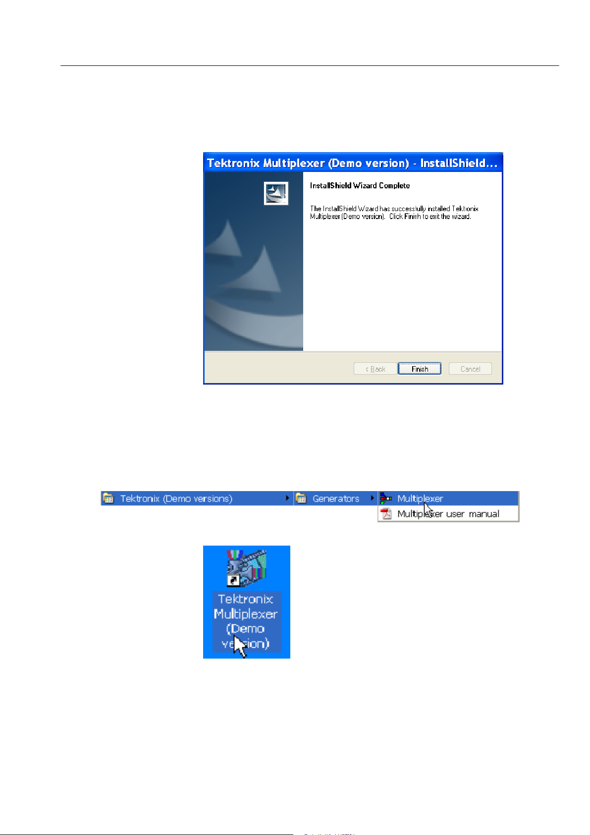
3. Click Finish to exit the Wizard once the demo version i s successfully
installed.
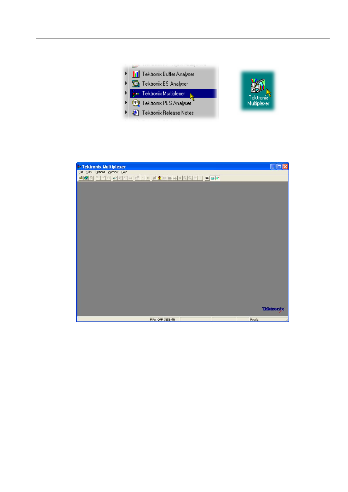
Starting the Program
Start the program by selecting the Multiplexer option from the Start > Programs
> Tektronix (Demo versions) > Generators menu or by double-clicking the
Tektronix Multiplexer (Demo version) shortcut on the desktop.
Multiplexer (Demo) User Manual
3
Page 12

Introduction to Demo Version
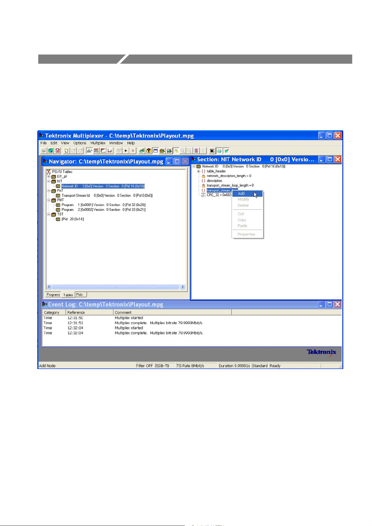
Initial Appearance
Once the demo program starts and is ready for use, it opens a main window as
follows:
Export Mode
The title bar of the main window shows Multiplexer to be a demo version.
The Export mode is disabled for the demo version. You cannot export data from
the Programs view (section data), the Tables view (section data), or the Pids view
(elementary stream and payload data).
All of the Export options (Export Payload, Export Elementary Stream, and
Export Section Data) of the Edit menu are also disabled.
4
Multiplexer (Demo) User Manual
Page 13
Introduction to Demo Version
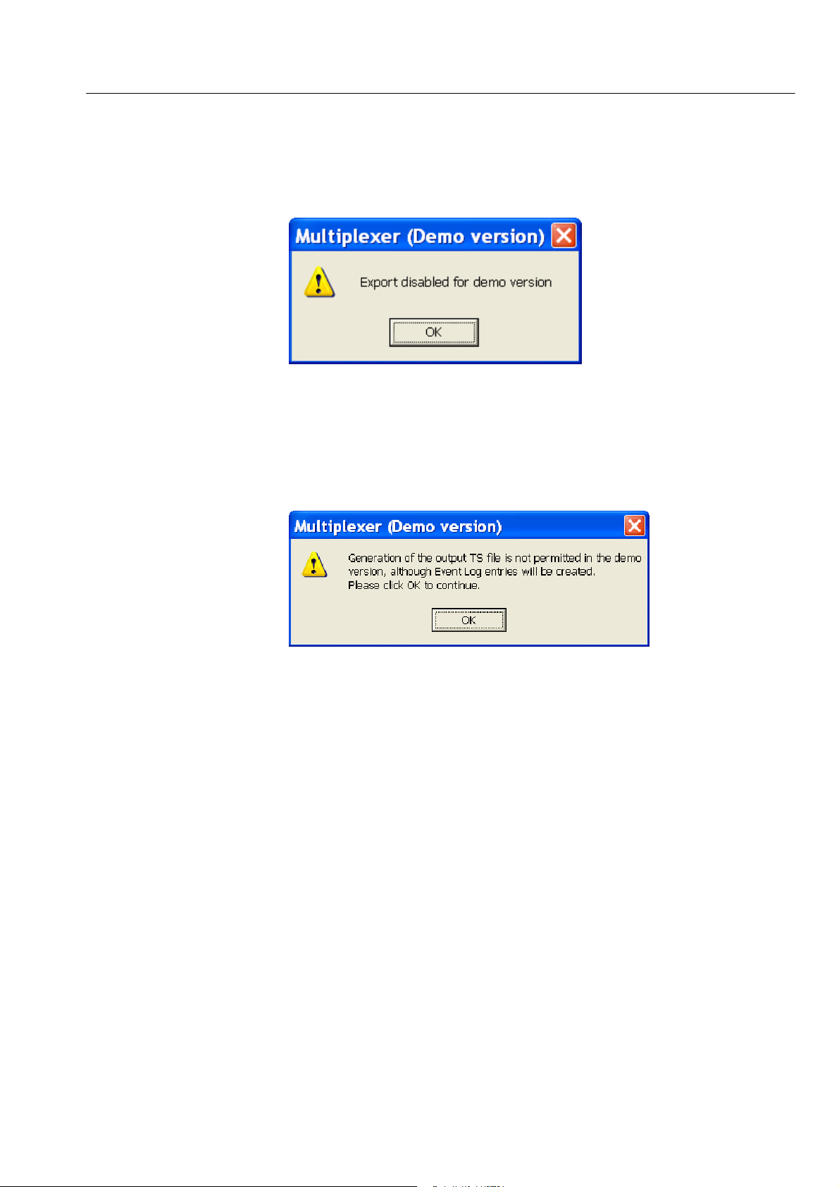
When you click the Export and Export As options of the File menu, the file is
not exported. Instead a message informs you that the export mode is disabled.
Multiplex Process
Pseudo Realtime Playout
The demo version does not generate an output TS file, so you will not be
prompted to save the output file. However, the Mux cycle will end.
When you start the Multiplex Engine, a message informs you that the output TS
file is not generated.
The Multiplexer in demo mode cannot play out the multiplexed files. The
Playout menu/toolbar option is disabled.
Multiplexer (Demo) User Manual
5
Page 14

Introduction to Demo Version
6
Multiplexer (Demo) User Manual
Page 15
Multiplexer - Getting Started
The Tektronix Multiplexer (Full version) provides off-line multiplexing of
ATSC, MPEG-2, DVB, and ISDB transport streams.
Multiplexer (Demo) User Manual
Transport streams (TS), elementary streams (ES), packetized elementary streams
(PES), Packet Identifiers (PID) can all be selected, manipulated and recombined
to form customized, synthesized transport streams. Program Specific Information
(PSI), Service Information (SI), and Program and System Information Protocol
(PSIP) are often referred to as simply SI in this section.
The functionality provided includes:
7
Page 16

Multiplexer - Getting Started
H Wizards that facilitate the completion of common tasks, such as populating
streams with Program Specific Information, Service Information, Program
and System Information Protocol (PS I/SI/PSIP), and programs.
H Table contents are displayed in and edited from structure diagrams (tree
diagrams).
H Transport Streams that either conform strictly to the standards selected for
interpretation or have precisely engineered, known, nonconformances.
H Two or more instances of Multiplexer can run concurrently. This allows table
information to be copied from one file to another.
H The source data for nonconformant streams can be saved in a raw format,
which can be quickly reloaded as the basis for generating more stream data.
H Conformance of edits to the standards is checked interactively and enforced
by default. Checking and enforcement can be turned off when specifying
nonconformances to be introduced into the new transport stream.
On opening, streams are analyzed and displayed according to the selected
standard: MPEG, DVB, ATSC, or ISDB. Scripts are used by the analysis
process; this allows private PSI/SI tables and descriptors to be defined.
Multiplexer in Playout
mode
NOTE. Most examples given in this section of the user manual are based on DVB
SI. Multiplexer is equally at home with all major DTV standards, MPEG-2,
DVB, ATSC, and ISDB as well as the major regions to those standards.
The Transport Stream Analyzer program should always be used for reliable
analysis of transport streams containing DSM-CC or MPE addressable sections.
In the absence of TS Analyzer, it is acceptable to use Multiplexer for analysis,
provided that the DSM-CC or MPE scripts are first applied using Expert mode
in the Stream Interpretation dialog box (see Scripts, page 13).
However, when you ar e multiplexing streams containing DSM-CC or MPE
addressable sections, the related scripts must not be active.
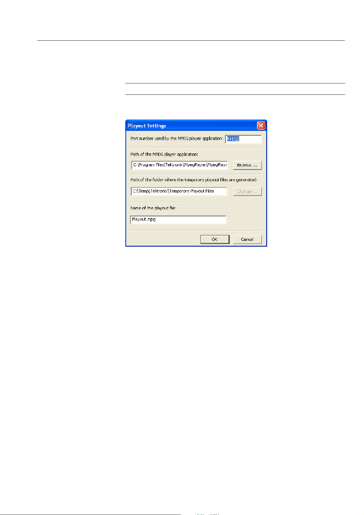
You can initiate a playout in the Multiplexer application using the playout feature
as soon as the multiplex operation is complete. Multiplexer creates a temporary
transport stream in the location specified by the Playout Settings and then
initiates a playout by loading this file into the player. To play the stream in the
loop mode, enable the loop mode in the Playout settings.
8
Multiplexer (Demo) User Manual
Page 17
Multiplexer - Getting Started
To open Playout Settings dialog box, select Multiplex > Playout settings.
NOTE. The Playout functionality is not available in demo version.
H.264 ES Input Characteristics
The H. 264 elementary streams used by the Multiplexer should comply with
ISO/IEC-14496-10/2005 R ec. H.264. The transport stream generated by the
Multiplexer should comply with ISO/IEC-13818-1/2000/AMD_3/2004.
H SEI (Supplemental enhancement information) stream support
The multiplexer detects a H.264 stream as an SEI stream if the following
conditions are met:
H VUI (video usability information) packet contains the coded bit rate.
H HRD (hypothetical reference decoder) parameters are specified in the
SEI packets.
H Non-SEI stream support
Those streams that are not detected as SEI streams are assumed to be
non-SEI streams.
PTS/DTS Timestamp
Generation
Table 1 lists the stream properties of H.264/AVC and generated transport stream
characteristics.
Multiplexer (Demo) User Manual
9
Page 18

Multiplexer - Getting Started
Table 1: PTS/DTS Timestamp Updates
H.264/AVC stream properties Comments Generated TS characteristics
SEI VUI
-- -- --
F -- --
F F --
F F F
BM(Valid Buffering Messages)
Stream without any
buffering messages
SEI NAL units potentially carrying private
data
SEI stream without full
HRD data
SEI stream with both
buffering period and
picture timing present
(HRD Compliant)
Bit rate Comments
Prompted or auto detected
Prompted or auto detected
Prompted or auto detected
Coded bit rate will be
auto-detected
TS will have PTS and DTS calculated at a constant frame rate from
the VUI parameters of the stream
unless you change the parameters.
If the stream does not have VUI
parameters 25 fps is taken as the
default.
TS will have PTS and DTS calculated at a constant frame rate from
the VUI parameters of the stream
unless you change the parameters.
If the stream does not have VUI
parameters 25 fps is used as the
default.
TS will have PTS and DTS calculated at a constant frame rate from
the VUI parameters of the stream
unless you change the parameters.
If the stream does not have VUI
parameters 25 fps is used as the
default.
TS will carry PTS and DTS as
coded by the SEI timing information.
Auto detection
Starting the Program
10
The stream bit rate is calculated as follows.
Bitrate =
Number of Frames∕ Frame Rate)
File Size
The program can be started by selecting the Tektronix Multiplexer option from
the Start > Programs menu or by double-clicking on the Tektronix Multiplexer
shortcut on the desktop.
Multiplexer (Demo) User Manual
Page 19
Multiplexer - Getting Started
Initial Appearance
Once the program has started and is ready for use, it will open a main window
that looks like the following illustration.
Initial Menu Options
Multiplexer (Demo) User Manual
Use the View menu to select a standard that will be used to interpret transport
streams, and then open a transport stream file or import a multiplex configuration file.
When the application is opened, you are presented with options relevant only to
opening new or existing multiplex files. Options that are not relevant at this time
are inactive (grayed out).
11
Page 20

Multiplexer - Getting Started
File Menu Options. Table 2 lists the options available in the initial File menu.
Table 2: File menu options
Command Function
New Opens a new multiplex configuration file.
Open Opens an MPEG file for use. The program opens the file
selection dialog box allowing you to choose the required file.
Examine TS Opens the Examine TS window, which allows a brief summary
of the stream to be viewed before it is subjected to full
analysis.
Close (Currently disabled - see page 23.)
Import... Opens a previously saved multiplex configuration file.
Export (Currently disabled -- see page 23.)
Export As (Currently disabled -- see page 23.)
1 <filename>
2 <filename>
3 <filename>
4 <filename>
Exit Finishes running the program.
A list of the four most recently used files. If the program has
recently been installed, the list might be empty or hold less
than four files.
Selecting a file name opens that file for use.
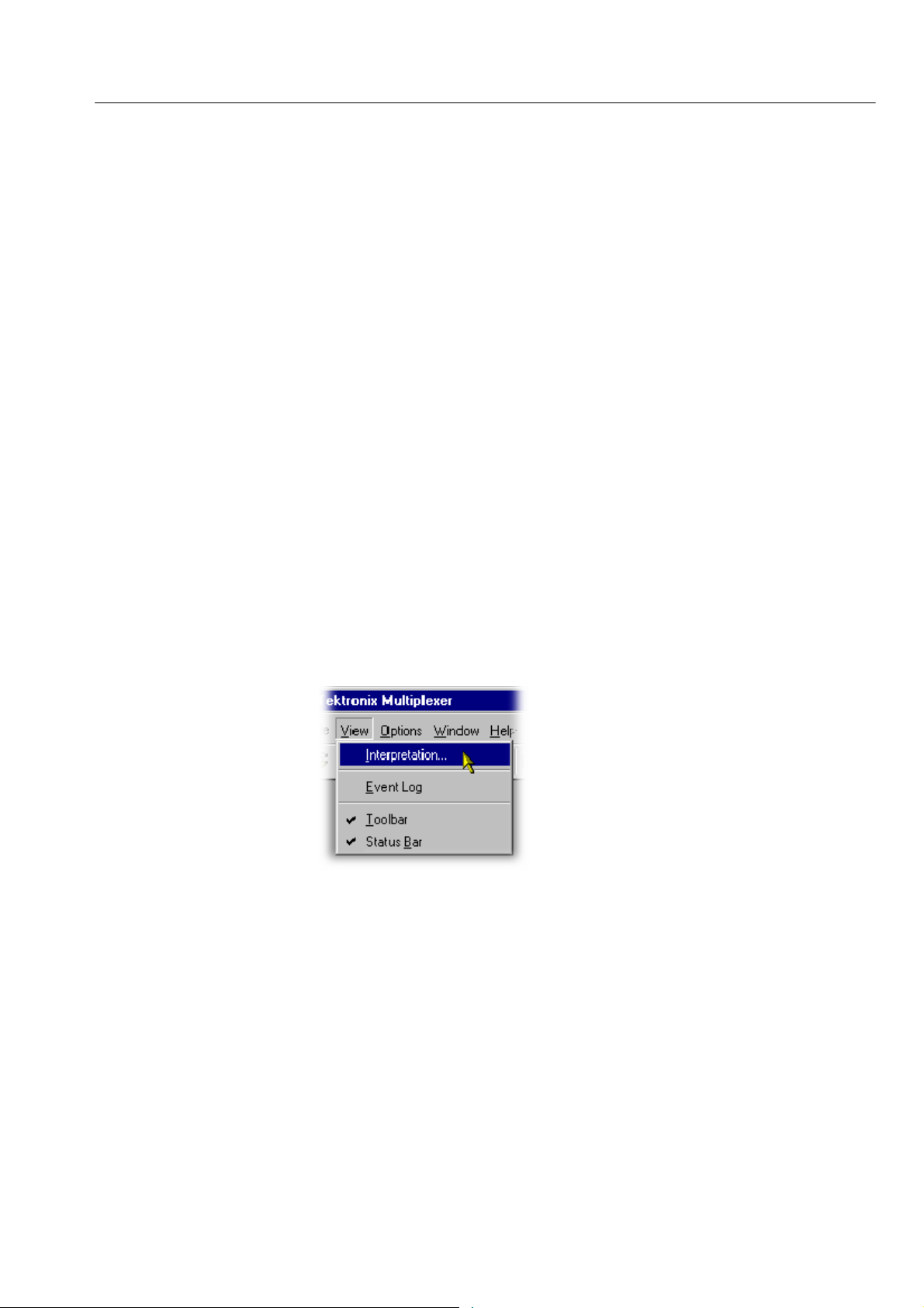
View Menu Options. Table 3 lists the options available in the initial View menu.
Table 3: View menu options
Command Function
Interpretation Opens the Stream Interpretation dialog box. This allows the
scripts to be used in stream analysis to be selected.
Event Log Opens the Event Log window.
Toolbar Displays or hides the Toolbar.
Status Bar Shows or hides the Status Bar.
A check mark next to an option indicates that the object is currently visible.
12
Multiplexer (Demo) User Manual
Page 21
Scripts
Multiplexer - Getting Started
SI scripts are necessary to enable SI table and descriptor data to be analyzed
successfully. Scripts are used to enable analysis of S I data dictated by the various
international standards, for example, MPEG-2, DVB, ATSC, and ISDB.
Essential scripts are installed and enabled using the Stream Interpretation dialog
box. In the absence of any enabled scripts, only the PAT table will be analyzed;
all other data will be presented as private data.
If a suitably configured script is selected and enabled before a stream is opened,
custom data will be analyzed when the stream is opened. If the script is not
selected or enabled, the stream will be analyzed, but any custom data will be
reported as either an error in the stream configuration or as an elementary stream
PID.
Scripts can be selected and enabled only when no files are open. The Stream
Interpretation dialog box is available when a file is open, but all activity is
disabled.
Handling Scripts
Note that a script file will not be used for analysis until:
H It is present in the Scripts text box in the current analysis mode.
H It is successfully enabled by closing the Stream Interpretation dialog box
using the OK button.
To open the Stream Interpretation dialog box, with all files closed, select
V iew > Interpretation.
Multiplexer (Demo) User Manual
13
Page 22
Multiplexer - Getting Started
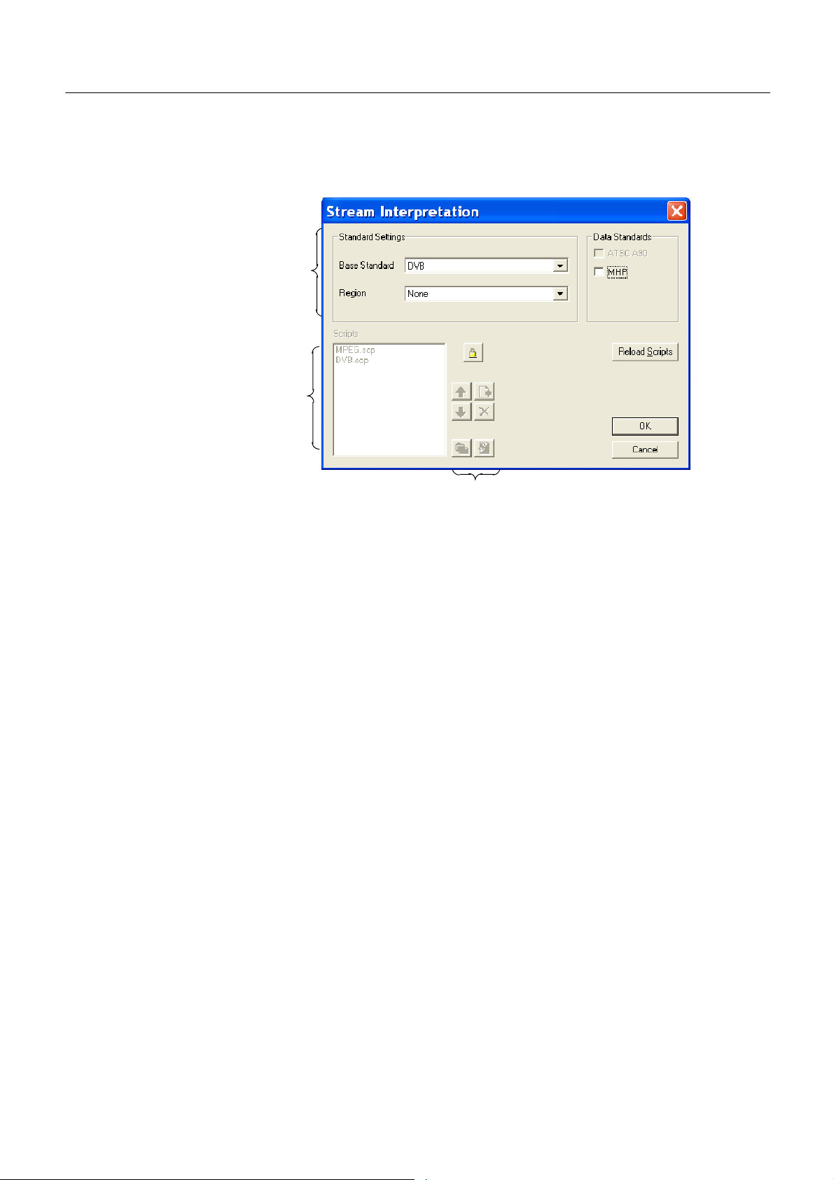
The Stream Interpretation dialog box is displayed as shown.
Script
Selection
Current
Selecting Scripts
Expert mode controls
The top half of the dialog box is concerned with selecting scripts. The text box
(Scripts) lists the scripts currently selected. The area adjacent to the text box is
dedicated to Expert mode controls.
The selection area of the Stream Interpretation dialog box is best viewed and
used from left to right.
The Base Standard drop--down allows the MPEG-2, DVB, ATSC, or ISDB
standard to be selected for analysis.
MPEG-2 only Interprets and analyzes the packets in conformance to
the MPEG-2 standards.
DVB Interprets and analyzes the Transport Stream Packets
according to the specifications of the DVB and MPEG-2
standards.
ATSC Interprets and analyzes the Transport Stream Packets
according to the specifications of the ATSC and
MPEG-2 standards.
14
ISDB Interprets and analyzes the Transport Stream Packets
according to the specifications of the ISDB and
MPEG-2 standards.
The selected standard will dictate the availability of the remaining options in the
Regions and Data Standards sections.
Multiplexer (Demo) User Manual
Page 23

Multiplexer - Getting Started
The Regions section allows country-specific regions to be added to the basic
standard scripts. If None is selected, only the standard scripts are listed in the
Scripts text box. The remaining country-specific regions add extra scripts to the
current listing. As with the Base Standard, the choice of Regions option will
dictate the availability of the options in the Data Standards section. The Custom
selection in the Regions section allows users t o include their own selection of
scripts using Expert Mode controls.
The Data Standards section offers a choice of data-specific scripts.
Note that the scripts listed by default are those resident in the default installation
directory (tektronix\scripts). Other directory locations can be specified in Expert
Mode. All selections will be retained between sessions.
Checking Syntax
Scripts are syntactically analyzed when the OK button is selected. They are also
checked when the application is opened. A fault in the syntax of a script will not
necessarily prevent a stream from being analyzed, but it might result in
incomplete analysis of the stream.
Scripts listed in the Scripts text box will not be used for stream analysis until
they have been successfully checked (the application has been opened or the
Stream Interpretation dialog box has been closed with no script-related error
messages issued).
An intermediate check of scripts listed in the S cripts text box can be made by
selecting the Reload Scripts button. This performs the same action as the OK
button but leaves the dialog box open.
Syntax errors will be indicated and reported in the Event Log (see page 69).
Multiplexer (Demo) User Manual
15
Page 24
Multiplexer - Getting Started
Expert Mode
Expert Mode allows you to select and customize the scripts to be used in
stream analysis and multiplexing. Note that when the expert mode is selected,
the Custom region option is automatically selected and the management buttons
are enabled. In Expert mode, all scripts become available t o be added to the
script list. The scripts will be checked and loaded, ready to be used for analysis,
when the OK button is selected.
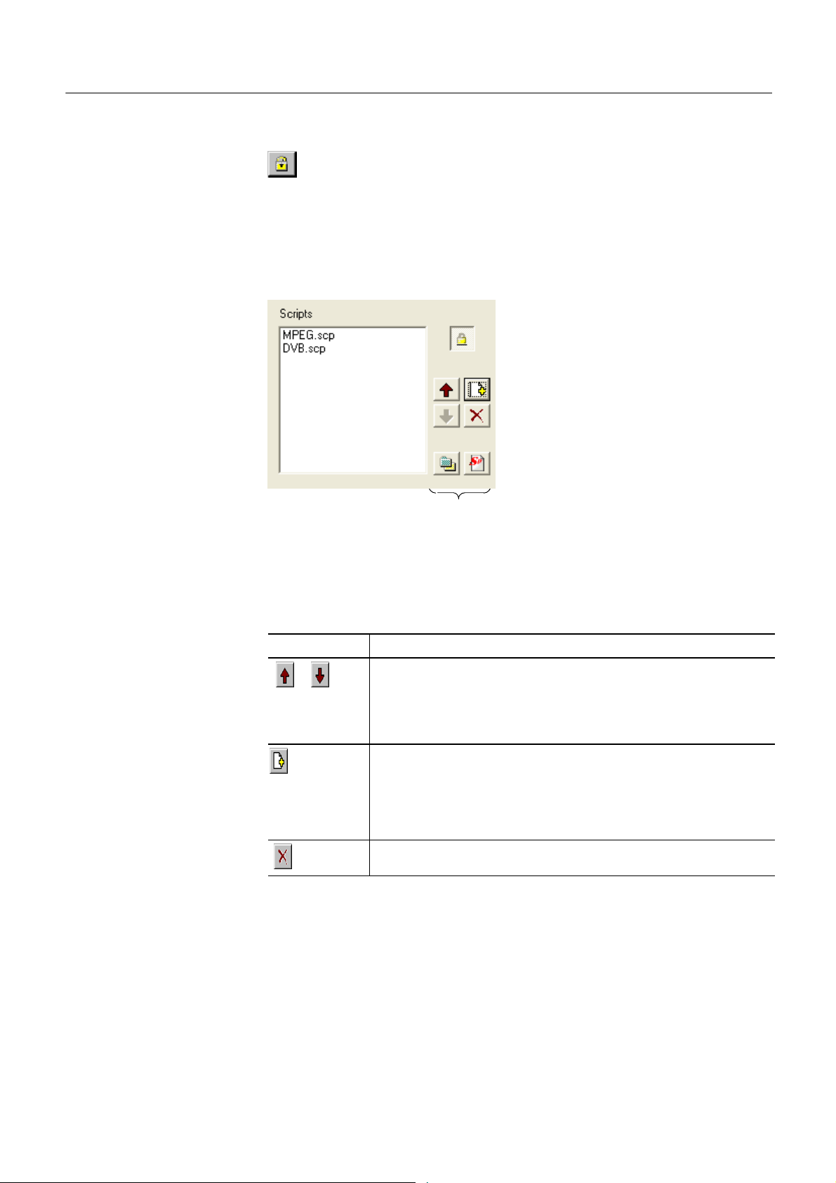
Script Management
The script management buttons act on the scripts currently listed in the Scripts
text box.
Table 4: Script Management
Buttons Function
Script files are parsed in the order that they are listed; in some circumstances this might be important. To move a file in a list, highlight the file
name and select the Up or Down arrow button as required. Each press of
the button will move the file up or down one place in the list until it reaches
the top or the bottom.
Add a script to the list: A standard Windows file selection dialog box is
opened. The default file extension is .scp. Select the required file. The
selected script will be added to the bottom of the list. If necessary, move it
using the Up and Down buttons.
Scripts can be loaded from any directory.
Delete the highlighted script.
16
Multiplexer (Demo) User Manual
Page 25

Multiplexer - Getting Started
Table 4: Script Management (Cont.)
Buttons Function
Change scripts default directory: by default, all scripts are found in a default
directory created during installation (tektronix\scripts). This button can be
used to set a different default directory.
Note that all scripts supplied by Tektronix in the default installation are
installed in a single directory; as long as this directory is designated as the
default directory, they will work satisfactorily.
View highlighted script with the associated application; by default, script files
are associated with the ScriptPad utility.
For a script file to be viewed successfully, the file extension (.scp) must be
associated with a text editor in the Microsoft Windows environment. The MPEG
Test System installation program by default associates a script editing utility
called ScriptPad; you can use another text editor, for example, Microsoft
Notepad, if preferred. ScriptPad is a simple script editor that can be installed
with the MPEG Test System. Scripts can be viewed and edited as required
(depending upon the file permissions).
Opening a Stream
Opening an MPEG Stream
Two options are available when opening a stream for multiplexing: to open an
existing stream or to open a previously prepared multiplex configuration file.
Three options are available when preparing a stream to be multiplexed:
H Create a new null stream (using File > New)
H Open an existing stream
H Import a multiplexer configuration file
Any file holding a recorded or synthesized sample of a stream that conforms to
the relevant standards can be opened and used as a basis for a new multiplex.
Note that the Examine TS option (see page 70) can be used to preview stream.
Some nonconformant streams can be opened, although, only the conformant
parts can be edited usefully. Any tables that are carried in a conformant PID and
have the correct syntax will appear in the output transport stream, as will any
elementary streams (whether referenced by a table or not) which are i n the input
transport stream.
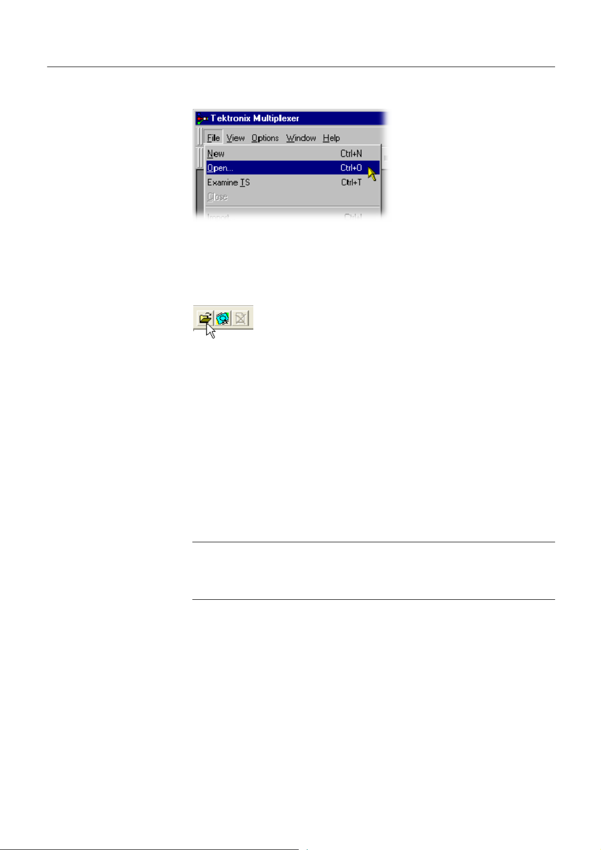
To open a file holding a transport stream, select the File > Open. If the required
file is in the list of recent files, it can be opened from the list using the Open File
dialog box.
Multiplexer (Demo) User Manual
17
Page 26
Multiplexer - Getting Started
Alternatively use the Ctrl+O keyboard shortcut or drag the file from Windows
Explorer and drop it into the Multiplexer window. A shortcut button is available
on the Toolbar for opening a file.
Opening Multiplex
Configuration Files
Any file holding a recorded or synthesized sample of a stream, which conforms
to the relevant standards, can be opened. Many nonconformant streams can be
opened provided that the PAT, PMT, and MGT tables correctly specify all the
other tables and their PIDs.
Multiplexer is used for generating both conformant and nonconformant streams.
Having generated a nonconformant stream, it might not be possible to successfully open it again in Multiplexer.
The specification for a new transport stream can be saved to a multiplex
configuration file. This also saves time for opening large MPEG files, since the
specification contains the results of the analysis from opening the original
MPEG file.
NOTE. The multiplex configuration file does not contain a copy of the transport
stream; instead it refers to the original MPEG file by the full path name.
Deleting or moving the MPEG file will result in a dialog box prompting for the
new location of the file.
Double-clicking on a *.muxml or *. mux file in Windows Explorer will open the
file in a new instance of Multiplexer.
18
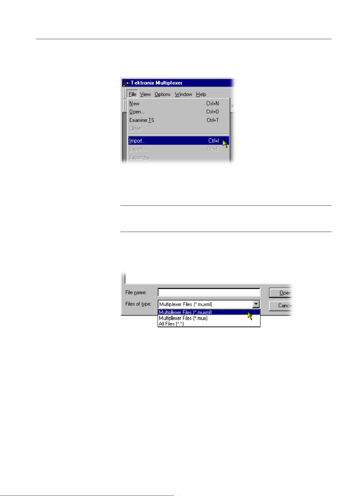
Importing a File. Importing opens a multiplex configuration file and the MPEG
file on which it is based.
To open a previously exported multiplex configuration file, select the
File > Import. If the required file is in the list of recent files, it can be opened
Multiplexer (Demo) User Manual
Page 27
Multiplexer - Getting Started
from the list to save using the Import file dialog box.
Alternatively use the Ctrl+I keyboard shortcut or drag the file from Windows
Explorer and drop it into the Multiplexer window.
Initial Stream Analysis
NOTE. Multiplexer reads the name and location of the MPEG file from the
multiplex configuration file and then opens it automatically. The previously
stored changes in the configuration file are applied to the display.
Note that the import dialog box offers a choice of file types: *.muxml, *. mux
and *.*.
The Navigator Tables view window is opened as soon as a file is opened or
imported. The program now starts to analyze the file with the loaded scripts to
determine what tables are present.
As the file is analyzed, the Top Levels of the Transport Structure diagram are
drawn in the Navigator window. The rightmost pane in the Status Bar at the
bottom of the program window shows the progress of analysis.
Multiplexer (Demo) User Manual
19
Page 28

Multiplexer - Getting Started
Files that are imported require less processing because they were analyzed in the
session from which they were exported.
What to Do Next
The file can now be manipulated to form a specification with which to synthesize
a new transport stream. Tables, elementary streams, and PIDs are viewed and
selected using the Navigator views. The components of any table selected in the
Navigator views are viewed and selected using the Section View window.
Tables, Programs and PIDs can be added and modified using the wizards
provided or manually. A selection of menu options is provided to facilitate
manipulation of the data.
The Multiplex menu has options to inhibit and reenable forced conformance to
the selected standards.
Having manipulated the file, a transport stream can be synthesized to the new
specification by the multiplex engine. The engine is started from the Multiplex
menu or using a toolbar button. The source file is used as reference data by
Multiplexer and the output written to a different file.
The illustration on page 21 gives an overview of the Multiplex process.
20
Multiplexer (Demo) User Manual
Page 29

Open/Import
Any file holding a recorded or synthesized sample of a
stream that conforms to the relevant standards can be
opened. See Opening an MPEG file.
Importing opens a multiplex configuration file and the
MPEG file on which it is based.
See Importing a File, page 18.
Transport Structure Demultiplex
As the file is analyzed, the Top Levels of the Transport
Structure diagram are drawn in the Transport Navigator.
See Initial Stream Analysis, page 19.
Multiplexer - Getting Started
Multiplexer (Demo) User Manual
Transport Structure Modifications
The file can now be manipulated to act as the specification
to synthesize a new transport stream. The tables and
elementary streams are viewed and selected either with the
aid of Wizards or in the Navigator windows.
Output/Export
The Multiplex Engine synthesizes a new transport stream
and writes it to an MPEG file.
To ensure that the specification for any synthesized stream
can be reused, it can be saved to a multiplex configuration
file.
See Multiplexing Transport Streams, page 125.
21
Page 30
Multiplexer - Getting Started
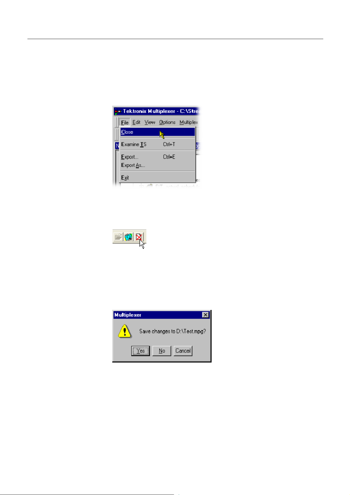
Closing Files
To close the files, select File > Close. This will close both the MPEG file and
any multiplex configuration file that is open.
A shortcut button is also available on the Toolbar for closing a file, which has a
standard file close symbol.
If a multiplex configuration file has been edited, and the changes not exported,
the program will ask if the file should be saved.
Select Yes to export the file, No to close the file without saving, or Cancel to
undo the close command and keep the file open.
22
Multiplexer (Demo) User Manual
Page 31

Menus and Controls
This section describes the various menu options, toolbar controls, status bar,
icons, and user interface.
Menu Options
The following pages describe all of the menu options. Since many of the options
are context sensitive, they will be available only when their function is appropriate for the selected display or window element. When a menu option is not
available, the option is grayed out.
File menu options
Table 5 lists the options available in the File menu.
Table 5: File menu options
Command Function
Close Closes the current file. This option is available as soon as
analysis starts. If the wrong file is being opened, or the wrong
options are selected, selecting this option will abandon the
analysis and close the file.
Examine TS Opens the Examine TS window, which allows a brief summary
of the stream to be viewed before it is subjected to full
analysis.
Export... Exports the current multiplex specification in a form that can be
imported even if it no longer generates a conformant transport
stream. This option is disabled when no file is open.
Export As... Exports the current file, as above, and allows a different file
name to be specified. This options is disabled when no file is
open.
Exit Closes any file that is open and terminates the program.
Multiplexer (Demo) User Manual
23
Page 32

Multiplexer -- Menus and Controls
Edit menu options
Table 6 lists the options available in t he Edit menu.
Table 6: Edit menu options
Command Function
Add Adds a table/section/loop to the currently selected item in the
Navigator or Section View.
Modify Edits the information in the currently selected field or item.
Delete Deletes the item currently selected.
Cut Cuts the current selection from the Window.
Copy Copies the contents of the current selection to the clipboard.
Paste Pastes data from the clipboard to the part of the transport
structure that holds that type of data.
Export Payload Extracts and exports the payload of the source transport
stream PID in the form of a simple data file.
Export Elementary Stream Removes the transport stream PID and PES headers and
exports the remaining information as a simple data file.
Export Section Data Extracts and exports section data. The created file can be
imported as ES using Multiplexer’s Add function or as SI using
the Import Section Data option (see next option).
View menu options
Import Section Data Imports SI data from a file and analyzes it. The section is
added to the Navigator view.
Table 7 lists the options available in the View menu.
Table 7: View menu options
Command Function
Interpretation Displays a read--only dialog box for viewing scripts that have
been selected for analysis (see also Initial Menu Options,
page 11).
Section View Opens the window and displays the table section currently
selected in the Navigator view.
Event Log Displays the list of events that are recorded in the Event Log.
Component Bit rate Displays a graphical comparison of the stream bit rates.
Component Duration Displays a graphical comparison of the stream component
durations.
Available Bit rate Displays a graphical view of the bit rate in the stream.
Properties Opens a properties dialog box for editing the currently selected
item in the Transport Navigator window.
24
Multiplexer (Demo) User Manual
Page 33

Multiplexer -- Menus and Controls
Table 7: View menu options (Cont.)
Command Function
Zoom In Zooms in the Available Bit rate and Component Duration
views.
Zoom Out Zooms out from the Available Bit rate and Component Duration
views.
Synchronize Synchronizes zoom levels of the Available Bit rate and
Component Duration views (toggle).
Show Cursor Shows or hides the cursor in the Available Bit rate and
Component Duration views.
Toolbar Shows or hides the Toolbar.
Status Bar Shows or hides the Status Bar.
Options menu options
Table 8 lists the options available i n the Options menu.
Table 8: Options menu options
Command Function
Display Filter Opens the SI Filter dialog box.
Single Section View Selects single or multiple section view. When disabled, multiple
section views can be opened.
Program Wizard Invokes the Program wizard.
Transport Wizard Invokes the Transport wizard.
Scan Settings Opens the Scan Settings dialog box.
Multiplexer (Demo) User Manual
25
Page 34

Multiplexer -- Menus and Controls
Multiplex menu options
Table 9 lists the options available in the Multiplex menu.
Table 9: Multiplex menu options
Command Function
Start Starts the Multiplex Engine, to synthesize a new transport
stream file.
Stop Aborts multiplexing. The output file is closed and contains all of
the data synthesized up to the point where the multiplex engine
stopped. This option is available only while the Multiplex
Engine is running.
Standard Mode Enforces conformance to the selected standards when editing
some fields that can be generated automatically.
Expert Mode Inhibits the above conformance checking so that nonconfor-
mant files can be created.
Report Provides the option of printing all or part of the transport
structure to either a file or a printer.
Seamless When enabled, the program specified in Seamless Settings is
processed and made seamless.
Seamless Settings Opens a dialog box in which the Make seamless parameters
are specified.
Playout When enabled, generates and captures
MPEG--2 transport streams that are compliant
with ATSC, DVB, and ARIB standards. This option is not
available in demo version.
Playout Settings Opens the Playout Settings dialogbox in
which, the path of the MPEG player application
and the folder where the temporary files are
specified. This option is not available in demo version.
Loop Sets whether the stream is output using the looping method.
This option is not available in demo version.
Update Opens a dialog box in which the parameters
in a stream are updated when looped. This option is not
available in demo version.
26
Multiplexer (Demo) User Manual
Page 35

Multiplexer -- Menus and Controls
Window menu options
Help menu options
Table 10 lists the options available in the Window menu.
Table 10: Window menu options
Command Function
Cascade Cascades the open windows when Options > Single Section
View is disabled.
Tile Tiles the windows horizontally when Options > Single Section
View is disabled.
Arrange Icons Aligns icons of any minimized windows at the bottom of the
program’s main window.
1 <window title>
2 <window title>
3 ... etc.
Makes the named window active, putting it on top of any
windows that had been hiding all or part of it.
Table 11 lists the options available in the Help menu.
Table 11: Help menu options
Command Function
About Multiplexer Opens a dialog box that displays the program version number.
Toolbar
Toolbars provide a set of convenient shortcuts for the more frequently used menu
options. The buttons are context sensitive and are enabled or disabled depending
upon the currently highlighted view or the action being performed.
The Toolbar can be hidden from view by selecting View > Toolbar.
Multiplexer (Demo) User Manual
27
Page 36
Multiplexer -- Menus and Controls
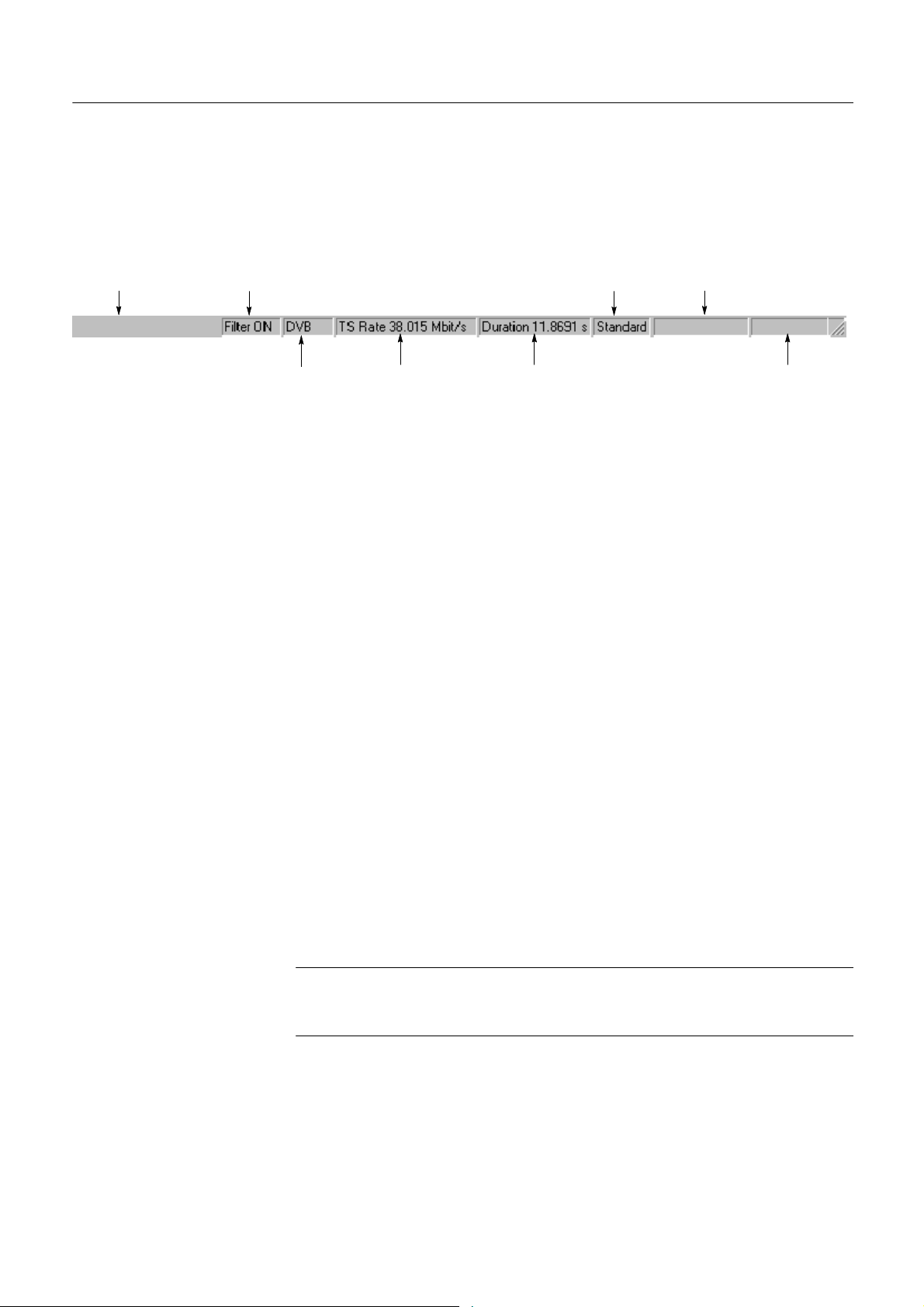
Status Bar
The Status Bar might be hidden from view, but when displayed it is always at the
bottom of the main window. For example:
Message Filter
ProcessingUser mode
Standard
interpretation
TS Rate T S Duration Progress
The following information is displayed from left to right on the Status Bar:
Message Field Provides a description of any button or menu option
over which the cursor pointer is placed. Other noncritical messages might also be shown.
Filter Status Indicates the status (On/Off) of the SI Filter.
Standard Interpretation Indicates the selected standard with which the file is pro-
cessed: MPEG-2, ATSC, DVB, or ISDB.
TS Rate & Duration Shows the transport stream rate and the duration at that
rate. A default rate is displayed during initial analysis.
28
User Mode Shows User mode selected: Expert or Standard. The
Standard mode prevents changes to certain fields. The
Expert mode enables editing.
Processing Status Indicates the progress (%) during initial analysis and
multiplexing.
Processing Progress Indicates the progress during i nitial analysis and multi-
plexing.
The Status bar can be hidden from view by selecting View > Status Bar.
NOTE. The status bar (Standard interpretation) displays ISDB--T SS whenever
the ISDB interpretation with Single segment extension is selected. Similarly,
when the Brazil Single segment is selected, the status bar displays ISDB--TB SS.
Multiplexer (Demo) User Manual
Page 37
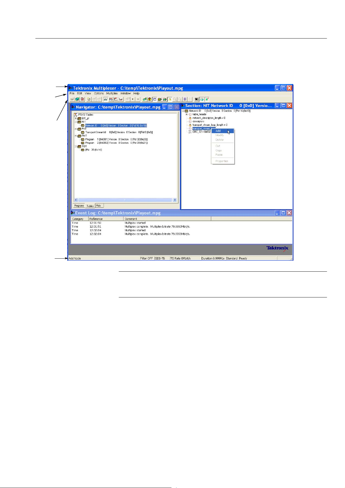
User Interface
Title bar
Menu
bar
Toolbar
Multiplexer -- Menus and Controls
Right--click menu
Navigator area
Section area
Status
Log View
NOTE. The Menu Bar contains the complete selection of options available in the
Multiplexer. Shortcuts to options are available through the toolbar and
context-sensitive shortcut menus.
Multiplexer (Demo) User Manual
29
Page 38
Multiplexer -- Menus and Controls
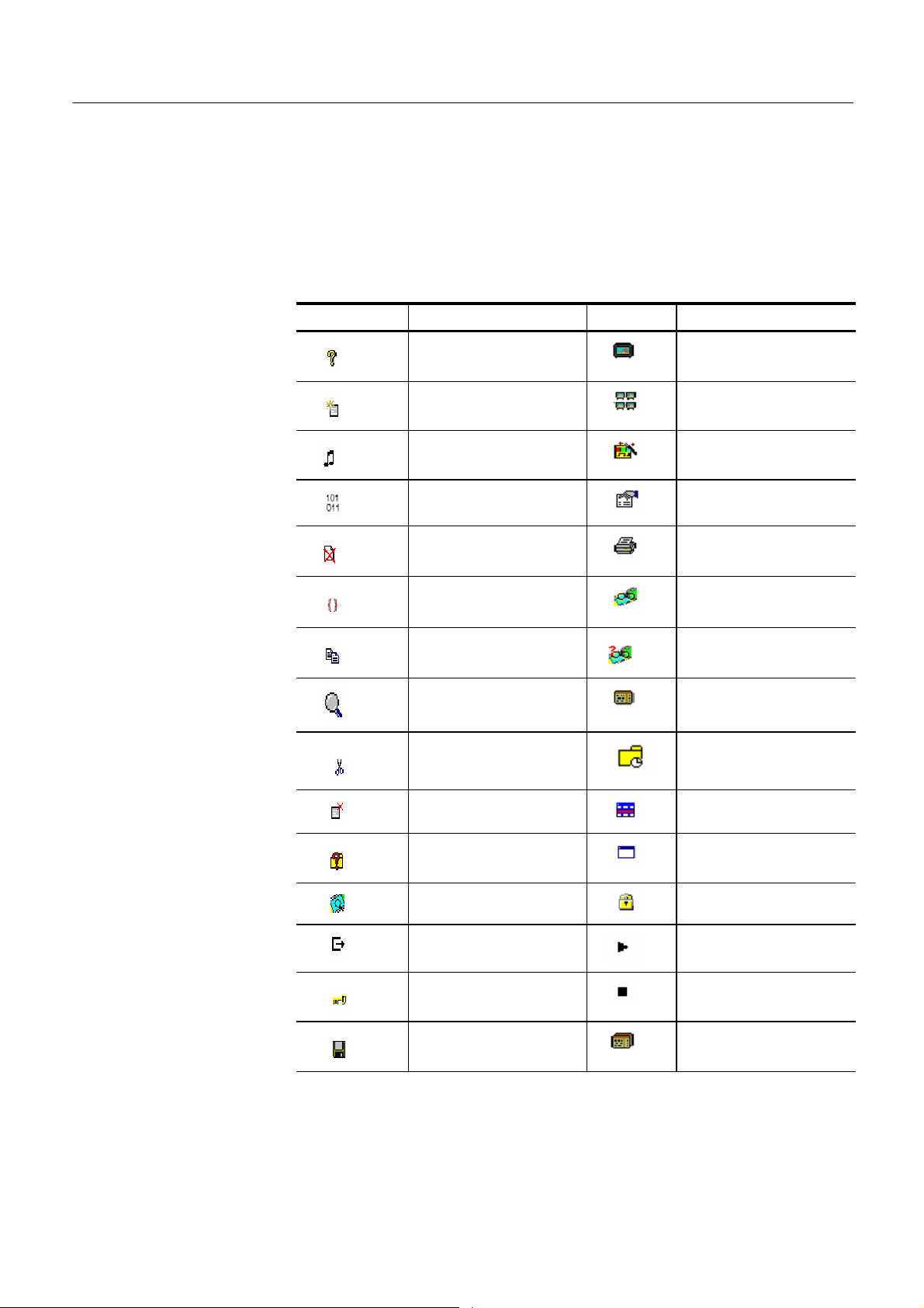
Icons
Icons are used throughout the Multiplexer user interface to assist you to identify
components and make visual links with toolbar shortcuts and menu options.
The following table lists all the icons used.
Table 12: Icons
Icon Description Icon Description
About Multiplexer Program
Add Program Group
Audio stream Program Wizard
Bit field Properties
Close Report
Container/Loop Seamless
Copy Seamless Settings
Current selection Section
Cut Section timing
Delete Section View
Display Filter dialog box Single window
Examine Transport Stream Standard mode
Exit Start
Expert mode Stop
Export Table
30
Multiplexer (Demo) User Manual
Page 39

Table 12: Icons (Cont.)
Icon DescriptionIconDescription
Export As Transport Stream icon
Export Elementary Stream Transport Wizard
Export Payload Unknown
Export Section Data Video stream
Import Section Data View Event Log
Modify View Component Duration
New View Component Bit rate
Multiplexer -- Menus and Controls
Open View Available Bit Rate
Paste
Playout
Loop
Update
NOTE. The Playout, Loop and Update icons are not available in demo version.
Multiplexer (Demo) User Manual
31
Page 40

Multiplexer -- Menus and Controls
Cutting and Pasting
Table types, sections, and PIDs can be cut, copied, and pasted using the
Windows clipboard. Only one selection can be held on the clipboard at a time.
Alternatively, a selection can be dragged and dropped using the mouse.
Cutting a Selection to the Clipboard. A selection (table type, section or PID) can
be deleted and automatically placed on the Windows clipboard. It can then be
pasted to a different file or back into the current file. Highlight the selection in
the Navigator Tables or PIDs view and select Edit > Cut or use the Ctrl+X
keyboard shortcut.
Copying a Selection to the Clipboard. A selection (table type, section or PID) can
be copied to the Windows clipboard. F rom t he clipboard, it can be pasted to a
different file or back into the current file.
Highlight the required selection in the Navigator Tables or PIDs view and then
select Edit > Copy or use the Ctrl+C keyboard shortcut.
Pasting a Selection from the Clipboard. More than one instance of Multiplexer can
run concurrently on a machine. A selection (table type, section, or PID) can be
pasted from the clipboard into any open transport stream file. The contents of the
clipboard are not affected by the paste operation, so the section can be pasted to
many files and more than once to the same file.
Activate the Navigator Tables or PIDs view of the required transport stream file
(that is, in an instance of Multiplexer). Then select Edit > Paste or use the
Ctrl+V keyboard shortcut.
The section/version is always appended to the end of the list under the appropriate table. Program/version numbers are automatically created. If the table is not
present in the multiplex configuration, it will be created automatically.
32
Multiplexer (Demo) User Manual
Page 41

Multiplexer -- Menus and Controls
Dragging and Dropping
A concept familiar to Windows users is “drag and drop” in which files can be
highlighted by clicking on them with the mouse and then dragged and dropped to
a new location, either in the same application or across applications.
In Multiplexer, the main uses of the drag and drop feature are to modify
multiplexes and to build new ones.
Elements can be dragged within Multiplexer, or from the Multiplexer Browser,
Windows Explorer or other instances of Multiplexer.
Program references and numbering will be automatically added and/or updated
when a new program is dropped onto the Navigator Programs view.
NOTE. Only the MPEG aspects of the transport structure are updated. Tables
specific to DVB and ATSC are not updated.
Manipulation in Program view. The following manipulations are available in the
Program view:
H When using Navigator Program view, a program can be copied or dragged.
The program can be dropped only on the transport stream node of the
Program view.
H Only the standard MPEG elements are copied, namely the PAT entry, the
PMT section and the elementary streams. S t andard dependent information is
not copied, for example, DVB SDT.
H Where a conflict occurs with the target, new values will be allocated for the
Program and PID numbers.
H Elementary streams can also be dragged and dropped between Program
Views. They can be dropped only onto the elementary stream root node.
H An elementary stream can have a stream type, a component tag and
descriptors associated with it; this information is retained during a drag and
drop in the program view. The program view displays this information when
the properties dialog box is activated.
Multiplexer (Demo) User Manual
33
Page 42

Multiplexer -- Menus and Controls
34
Multiplexer (Demo) User Manual
Page 43

Wizards
In the Navigator Programs view, wizards provide you with a step-by-step
approach to building streams to be multiplexed by offering defaults for PSI/SI
and t he opportunity to include user-selected programs. The standard previously
selected in the Interpretation dialog box will dictate which PSI/SI components
are offered.
There are two major wizards: the Transport Wizard and the Program Wizard.
Other minor wizards can be opened by these major wizards or they can be
opened in a new window to facilitate specific tasks, such as adding EIT
information. When configuring a new multiplex, the Transport Wizard is opened,
followed by t he Program Wizard; although, on completion of the Transport
phase, an opportunity to exit the wizard process is offered before the Program
Wizard opens. For some detailed operations, only the appropriate wizard can be
opened.
At their most basic level, wizards open, in a logical order, the property dialog
boxes t hat are available when building a stream manually.
The following paragraphs provide a step-by-step description of the wizards.
Wizard Controls
Transport Wizard
The following control buttons are provided on the wizard dialog boxes where
relevant:
Next Retain changes made using this dialog box and
move to next dialog box.
Back Discard changes made using this dialog box and
return to the previous dialog box.
Cancel Exit the wizard and discard all changes.
Finish Exit the wizard and implement all changes.
Toolbar icon:
The Transport wizard allows you to easily create a basic stream populated with
the PSI/SI necessary to hold program information. It can also be opened when
PSI/SIistobeaddedtoanexistingstream.
Multiplexer (Demo) User Manual
35
Page 44

Multiplexer -- Wizards
Creating a New Transport
Stream
The following steps show the screens used in the creation of a DVB stream.
NOTE. When the Transport Wizard is used to populate a new stream, if the
defaults in the various dialog boxes are retained, then the resulting stream will
conform to the selected standard.
1. Open a new file; F ile > New.
2. Select the Program tab in the Navigator view.
3. Select and highlight the Transport Structure element; at this stage in the
creation of a new stream, t his will be the only element visible in the Program
Navigator view.
4. Select Add from the shortcut menu.
36
Multiplexer (Demo) User Manual
Page 45

Multiplexer -- Wizards
The Transport Stream Settings dialog box allows you to set up the transport
stream identity (part of the PAT section) and version. Adjustments can also
be made to the PAT timing, if required, by selecting the PAT button.
PAT timing - see Editing PSI/SI Table Properties, page 98.
NOTE. You cannot add a PAT with the ISDB or ISDB--TB interpretation and
Single segment extension selected. When you click Add, Add a Program wizard is
displayed instead of the Transport Stream Settings.
5. Select Next to move to the Optional Tables dialog box.
6. This dialog box allows you to include, and if required, configure basic
PSI/SI information.
Multiplexer (Demo) User Manual
37
Page 46

Multiplexer -- Wizards
As the check box next to each table is enabled, the table name is added to the
graphical representation on the left. The associated buttons are also enabled
to allow timing or other aspects of the table to be modified.
NIT, TOT, and TDT Timing - see Editing PSI/SI Table Properties,page98
38
Multiplexer (Demo) User Manual
Page 47

NIT Settings
Multiplexer -- Wizards
To set up the Network Information Table (NIT), enter or select the required
values and select the OK button. Note that if a Delivery System other than
Undefined is selected, an additional settings dialog box becomes available,
specific to the Delivery System chosen.
Multiplexer (Demo) User Manual
39
Page 48

Multiplexer -- Wizards
7. Select Next to move to the Transport Wizard Complete dialog box.
This dialog box allows you to review the changes made by the wizard before
confirming the process.
The process can be cancelled, thereby losing all changes, by selecting the
Cancel button.
At this stage in the creation of a new multiplex, if you want to add programs,
leave the Add Program Wizard check box enabled and select Next. If you want
to add them by some other means, clear the Add a Program Wizard check box.
The Next button label will change to Finish, which allows you to exit the wizard
and implement all changes.
When the Transport Wizard has closed, note that the Navigator views are
updated with the new PSI/SI.
40
Multiplexer (Demo) User Manual
Page 49
Program Wizard
Multiplexer -- Wizards
Toolbar Icon:
The Program Wizard allows you to add programs as required to a stream that is
already populated with basic PSI/SI. Each use of the Program Wizard allows the
addition of one program. Adding more programs requires the wizard to be
opened each time.
If a new stream is being created, the Transport Wizard offers an opportunity to
open t he Program Wizard. Alternatively, in the Navigator Programs view,
highlight the Programs node and select Add from the shortcut menu.
Adding a Program to a
Transport Stream
To add a program to the transport stream, follow these steps:
NOTE. If, when the Program Wizard is used to add programs to a stream, the
defaults in the various dialog boxes are retained, the resulting stream will
conform t o the DVB standard.
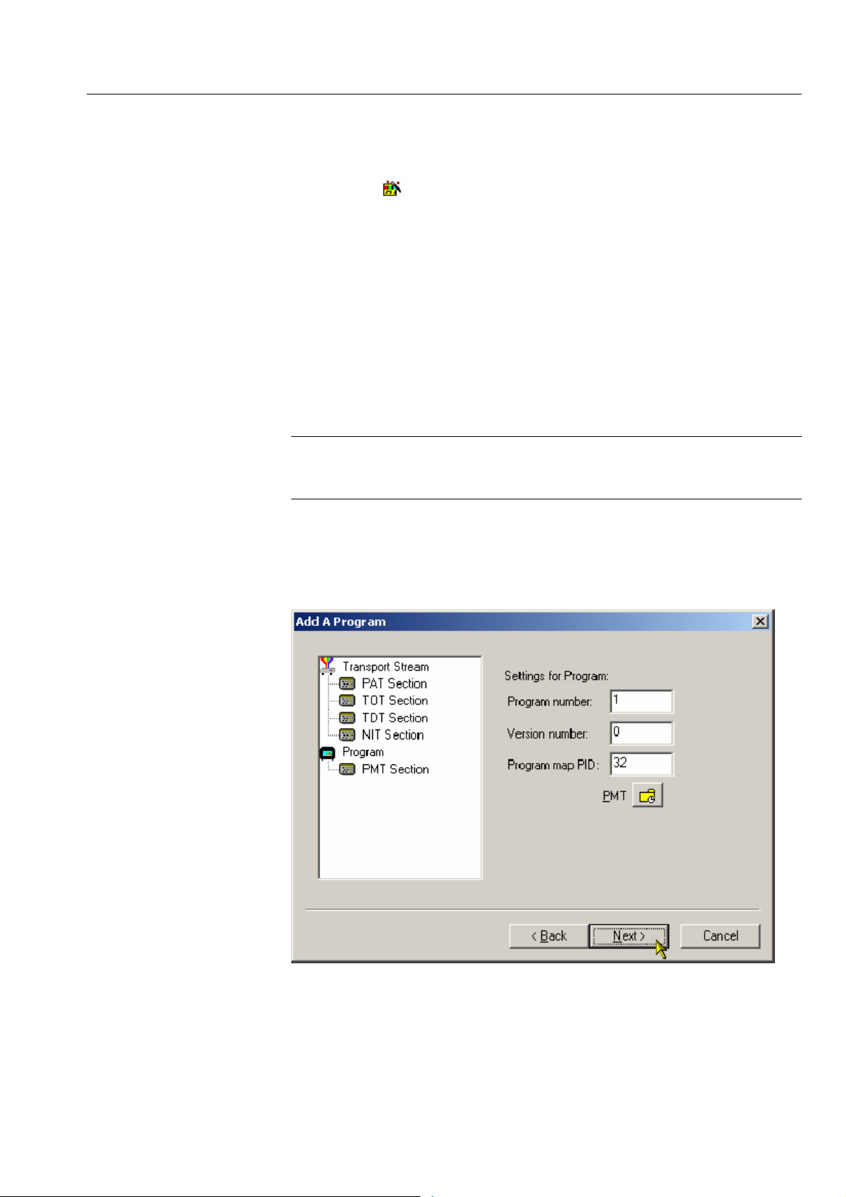
1. When you open the Program Wizard, either as a continuation of creating a
new stream or as an attempt to add a new program, a dialog box similar to
that shown below is displayed:
Multiplexer (Demo) User Manual
41
Page 50
Multiplexer -- Wizards
The values placed automatically in the three displayed fields will be the next
in the sequence of programs. (In the example screen, the stream contains no
prior programs, hence this is program number 1. PID 32 is used because that
is the first free PID after the reserved PSI/SI PIDs.)
PMT Timing - see Editing PSI/SI Table Properties, page 98.
2. Select Next to move to the Add Service Description dialog box.
NOTE. If ISDB interpretation with Single Segment extension is selected the
program number starts from 8 (default). However, you can enter numbers from 1
to 7.
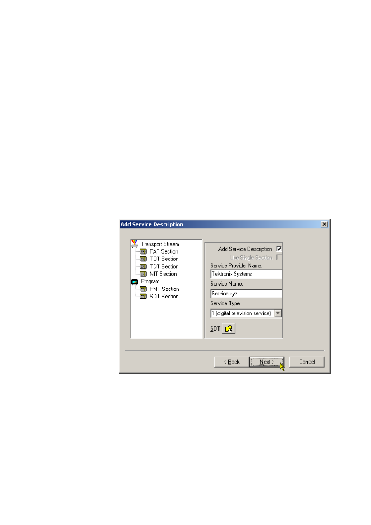
Service Description Dialog
Box
The Service Description dialog box allows you to identify the Service Provider
to be associated with a program.
42
3. By default, the Add Service Description check box is clear. When it is
enabled, a Service Provider Name and a Service Name must be entered and a
Service Type selected from the drop-down list. If no details are provided, the
section will still be created but the relevant descriptors will be empty.
Multiplexer (Demo) User Manual
Page 51
Multiplexer -- Wizards
Enabling the Use Single Section check box will cause the S DT descriptors to
be added to the existing SDT section. If the stream contains no SDT section,
the check box is disabled.
SDT timing - see Editing PSI/SI Table Properties, page 98.
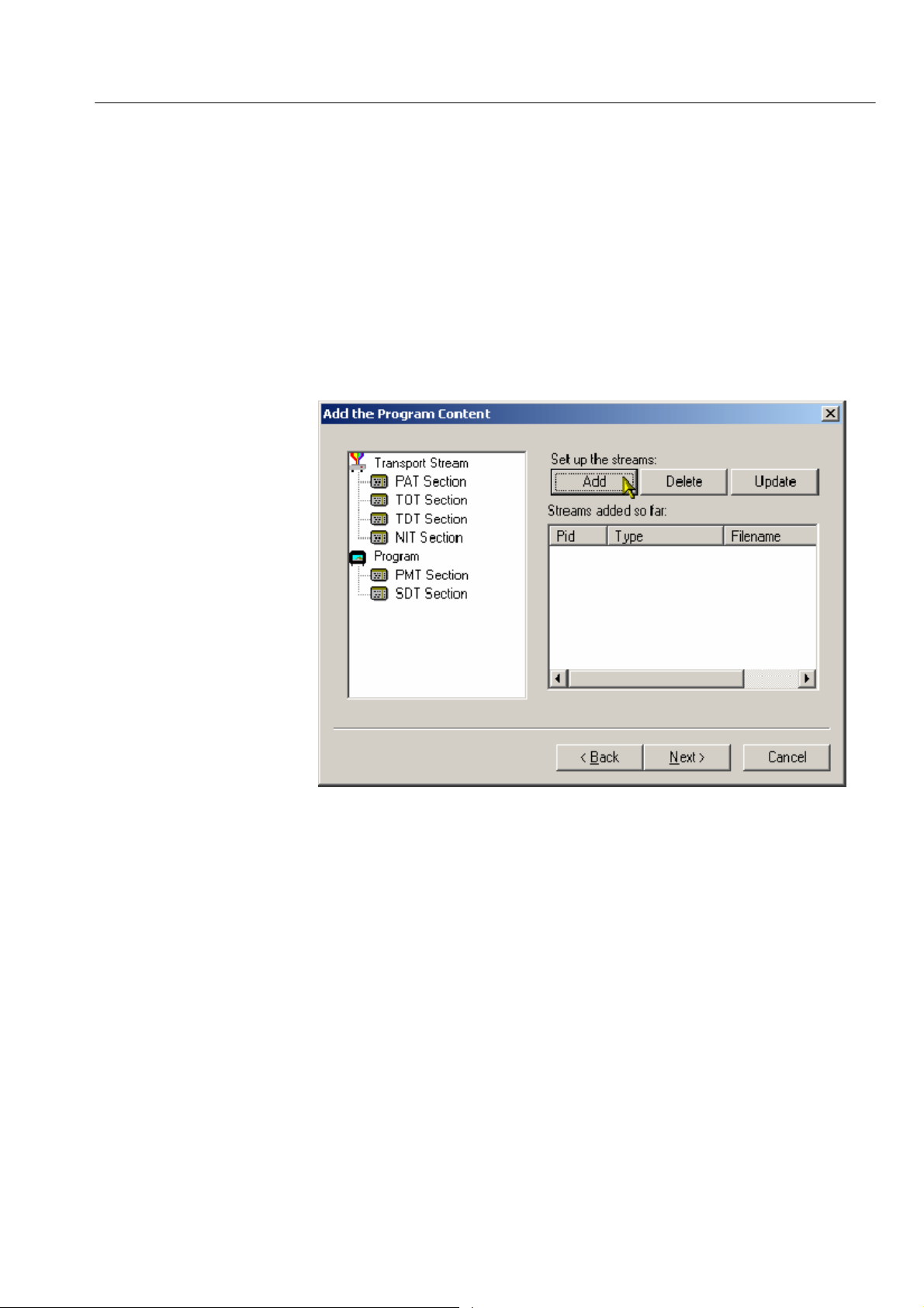
4. Select Next to move to the Program Content dialog box.
Program Content Dialog
Box
This dialog box allows you to compile a list of elementary streams to be
associated with the program in the final multiplex.
Multiplexer (Demo) User Manual
5. Select Add to display the Add Program Stream dialog box.
43
Page 52

Multiplexer -- Wizards
This dialog box allows you to identify elementary streams to be included in
the new multiplex. You must specify the PID and Stream Type of the new
stream. A C omponent Tag can also be allocated.
If the Component Tag is enabled, it can be referenced by other tables, for
example, the Event Information Table.
The dialog box consists of three tabbed pages that specify the source of the
stream, its timing within the multiplex, and whether it should be carrying a
PCR PID.
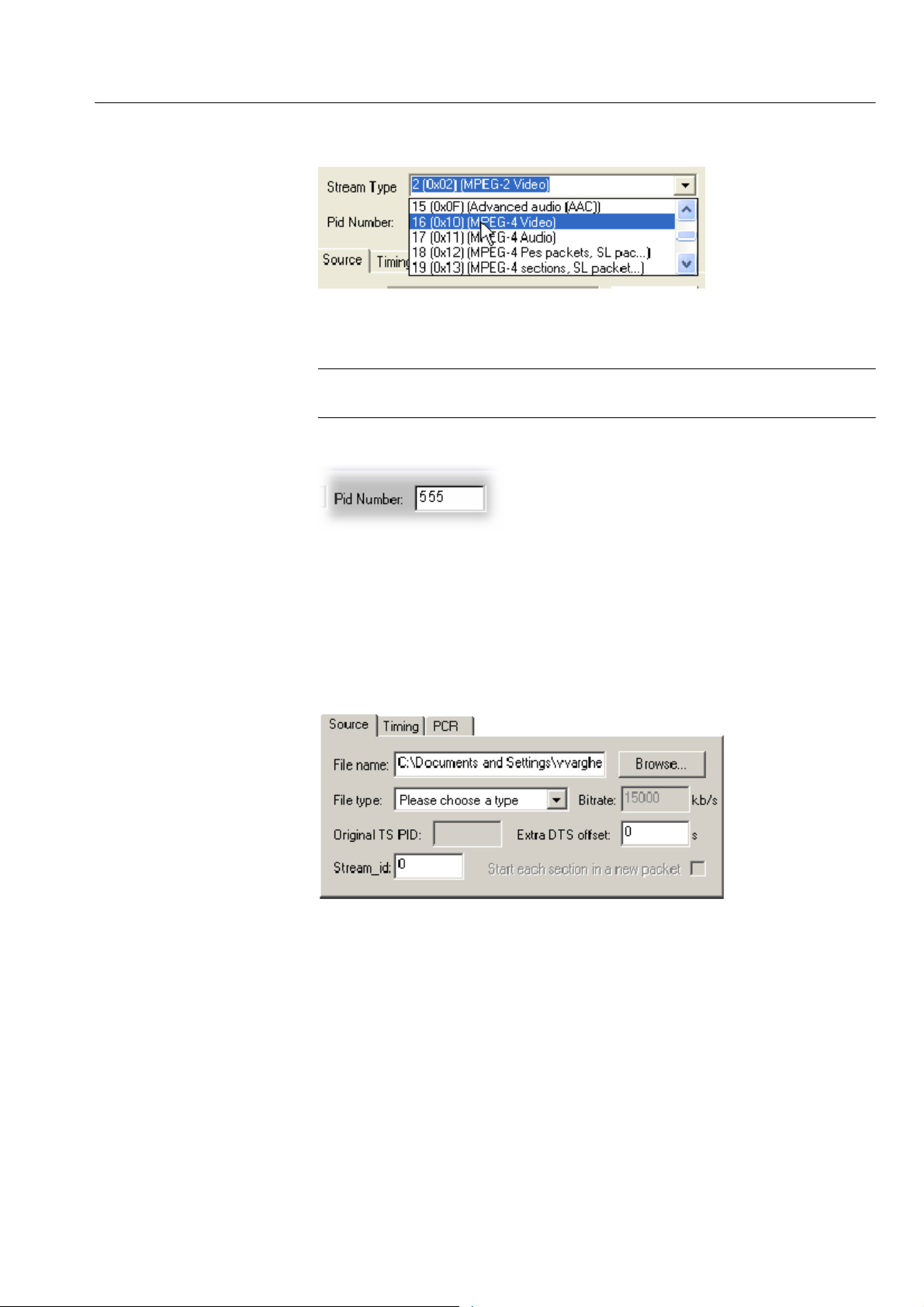
6. Select a Stream Type from the drop-down list.
44
Multiplexer (Demo) User Manual
Page 53
Multiplexer -- Wizards
This will be the S tream Type allocated to the stream in the new multiplex.
NOTE. The Stream Type drop--down list displays the previously selected stream
as the default type.
7. Allocate a PID Number in which the elementary stream is to be carried.
8. Enable the Component Tag check box, if required. Enter a Component Tag
number (0--255) in the enabled field.
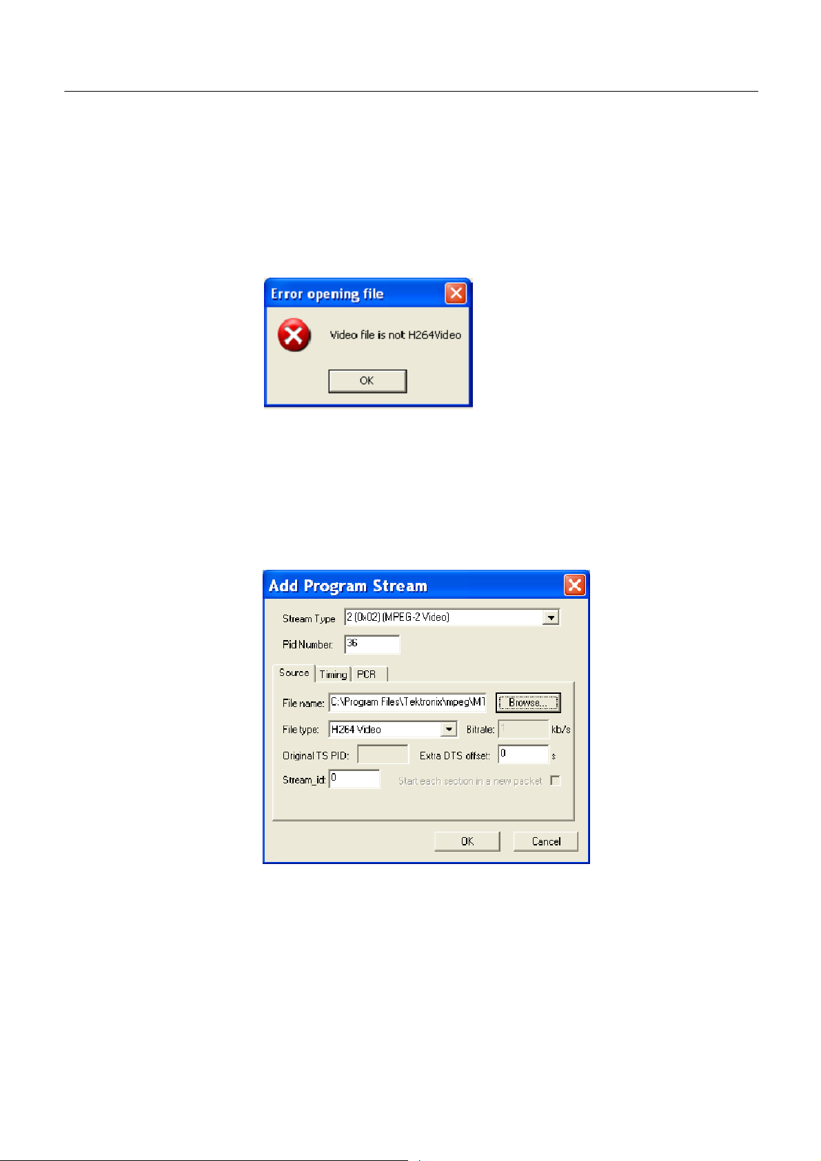
Source Tab. The Source tab of the Add Program dialog box is used to select and
specify elementary streams to be included in the new multiplex.
9. Enter an elementary stream File Name. You can enter it directly or use the
Browse button to open a standard Windows file selection dialog box.
10. Select the File type of the selected stream from the drop-down list.
Multiplexer (Demo) User Manual
H If you select MPEG-2 video, the bit rate is detected automatically and
displayed in the Bi t rate field.
H If you select H.264 video with SEI messages, the bit rate is detected
automatically and displayed in the Bit rate field.
45
Page 54
Multiplexer -- Wizards
H If you select H.264 video without SEI messages, the bit rate is not
detected automatically.
H When the selected file type does not match with the selected file name,
an error message is displayed and you will have to reselect the correct
file type.
The remaining fields on this tab will be enabled or disabled depending on the
Stream Type selected. Complete the enabled fields as necessary.
11. If you select H.264 video with SEI stream, a Suppress PTS/DTS insertion
check box is displayed. The PTS/DTS insertion can be suppressed by
selecting this check box.
46
Multiplexer (Demo) User Manual
Page 55

Multiplexer -- Wizards
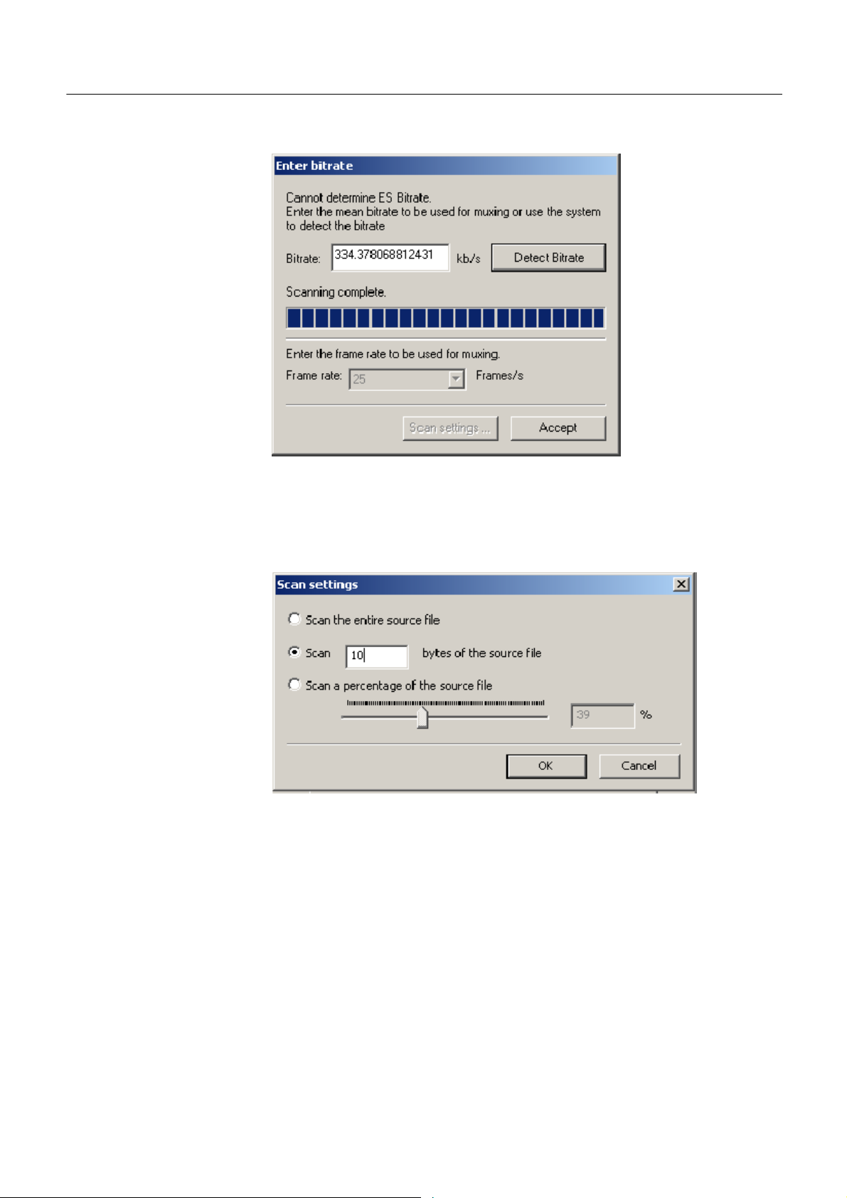
Enter Bit rate for H.264 non-SEI str eams. You can assign the bit rate in the
following ways:
H If you know the actual bit rate of the ES, enter the value in the Bit rate
field. Select the frame rate from Frame rate box and click Accept. The
entered bit rate will be displayed in the Bit rate field of the Source tab.
H If you want the Multiplexer to auto detect the possible bit rate, select the
Frame rate and click Detect Bit rate. A progress bar is displayed giving
the percentage of the scan completed and the bit rate is automatically
filled in the Bit rate field of the Source tab.
Multiplexer (Demo) User Manual
47
Page 56
Multiplexer -- Wizards
You can detect the bit rate by setting the scan value in the Scan settings
dialog box. Select the options accordingly to scan the entire source file,
bytes of the source file, or percentage of the source file.
48
Multiplexer (Demo) User Manual
Page 57
Multiplexer -- Wizards
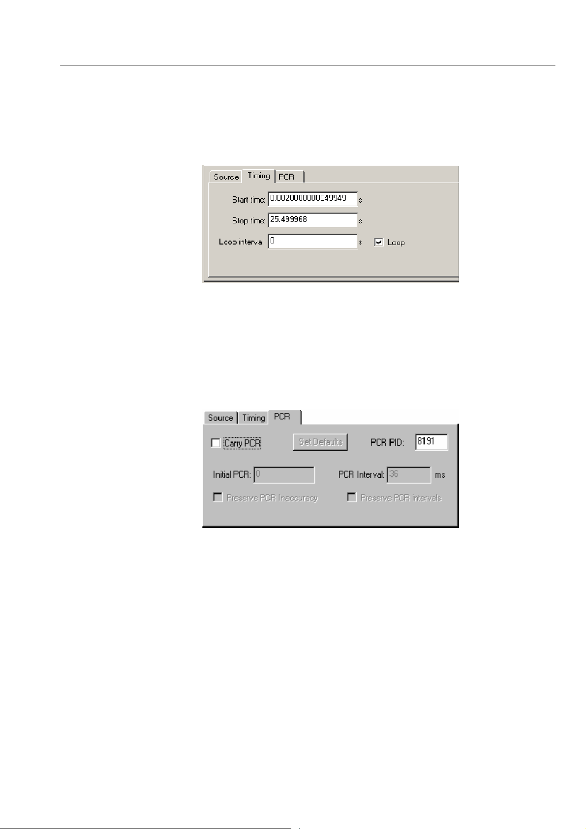
Timing Tab. The Timing tab of the Add Program dialog box is used to specify the
portion of the new multiplex that the selected stream will use. The default start
time is set to 0.002 s.
12. Complete the fields as required. The default settings assume that the stream
is to be carried throughout the new multiplex, looping if necessary.
PCR Tab. The PCR tab of the Add Program dialog box is used to specify whether
PCR information should be carried with the selected elementary stream or in a
separate associated PID.
13. If the PCR is to be held in an associated PID, disable the Carry PCR check
box and enter a PCR PID number.
14. If the PCR is to be carried with the stream, enable the Carry PCR check box
and complete the remaining fields as required.
Set Defaults returns the settings to their initial values.
Multiplexer (Demo) User Manual
49
Page 58

Multiplexer -- Wizards
15. Select the OK button to complete adding an elementary stream to the listing
in the Program Wizard.
16. More streams can be added using the Add button. Listed streams can be
deleted using the Delete button. Details of listed streams can be modified
using the Update button.
50
This completes the addition of one or more program streams.
17. Select Next to move to the Event Information dialog box.
For more details about the fields on these tabs, refer to Adding an Unreferenced
Elementary Stream, page 105.
Multiplexer (Demo) User Manual
Page 59

Multiplexer -- Wizards
Event Information Dialog
Box
The Event Information dialog box allows you to add Present and Following
event information.
18. If the Event Information Table (EIT) is to be included in the multiplex,
enable the Event Information Table check box.
19. Enable the Present and F ollowing check boxes as required.
Present/Following timing -
For more information on Present/Following timing see Editing PSI/SI Table
Properties, page 98.
Multiplexer (Demo) User Manual
51
Page 60

Multiplexer -- Wizards
20. Use the Settings buttons to open the Present/Following Events dialog box
and add and specify events as required.
21. Select Next to move to the Program Complete dialog box.
52
Multiplexer (Demo) User Manual
Page 61

Multiplexer -- Wizards
Program Complete Dialog
Box
The Program Complete dialog box provides you with a summary of the created
Transport Structure.
22. To confirm and implement the Transport Structure, select the Finish button.
Note that the proposed structure is created in the Navigator views.
This completes the procedure of adding a program to a transport stream using the
Program Wizard.
Multiplexer (Demo) User Manual
53
Page 62

Multiplexer -- Wizards
54
Multiplexer (Demo) User Manual
Page 63

Views
The Multiplexer contains a number of views, which are displayed in the working
area of the user interface. All of the views can be manipulated using conventional Windows techniques. The Navigator and Error Log views can be docked
against the edges of the UI or floated independently of the Multiplexer window.
The Section view can be manipulated within the Multiplexer window, including
tiling and cascading where multiple Section views are displayed.
Each available view displays a different aspect or level of detail of stream
analysis and manipulation.
Multiplexer (Demo) User Manual
55
Page 64

Multiplexer -- Views
Navigator Views
The Navigator view contains three subviews or tabs: Programs, Tables, and
PIDs.
Program Views
The Navigator Programs view extracts and displays system information that is
relevant to programs. Information t hat i s not directly related to programs (for
example, NIT), or that has not been incorporated into a program (for example,
elementary streams not listed in a PMT) will be omitted from the Program view.
The system information is still available for viewing in the Navigator Tables and
PIDs views.
56
Manipulation of programs and elementary streams should take place from the
Program view.
Multiplexer (Demo) User Manual
Page 65
Multiplexer -- Views
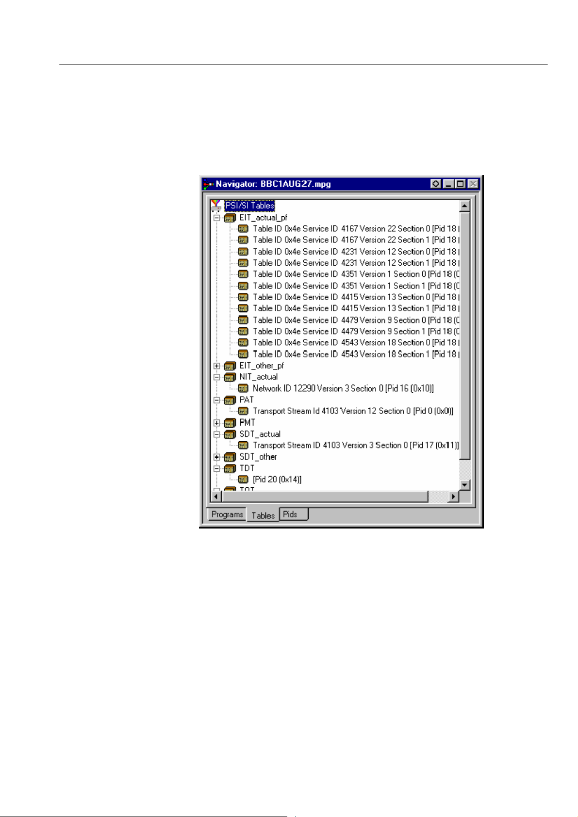
Tables View
The Tables view displays high-level structure of the Program and System
Information Protocol (PSIP), Service Information (SI), and Program Specific
Information (PSI) tables. More detailed payload information can be examined
and edited, for a selected section of a table, using the Section View.
Multiplexer (Demo) User Manual
Any PSI/SI information that the program cannot confidently analyze will be
shown in the PIDs view.
57
Page 66

Multiplexer -- Views
PIDs View
The PIDs view displays the PIDs contained in the stream. The PIDs are
displayed in ascending numerical order.
58
PSI/SI table types are identified in the section nodes of System Information
nodes.
Elementary stream PIDs are identified by source and type where possible.
Multiplexer (Demo) User Manual
Page 67

Section View
Multiplexer -- Views
The Section View displays the contents of the currently selected section in any of
the Navigator views.
The Section view is dynamic in that it will be instantly refreshed if a new section
is highlighted in the Navigator view. If no section is selected, the Section view
will be blank.
Thelockiconindicates that those items have restricted access due to the mode of user
operation: Expert or Standard.
- adjacent to certain elements of the table in the Section view
Multiplexer (Demo) User Manual
59
Page 68
Multiplexer -- Views
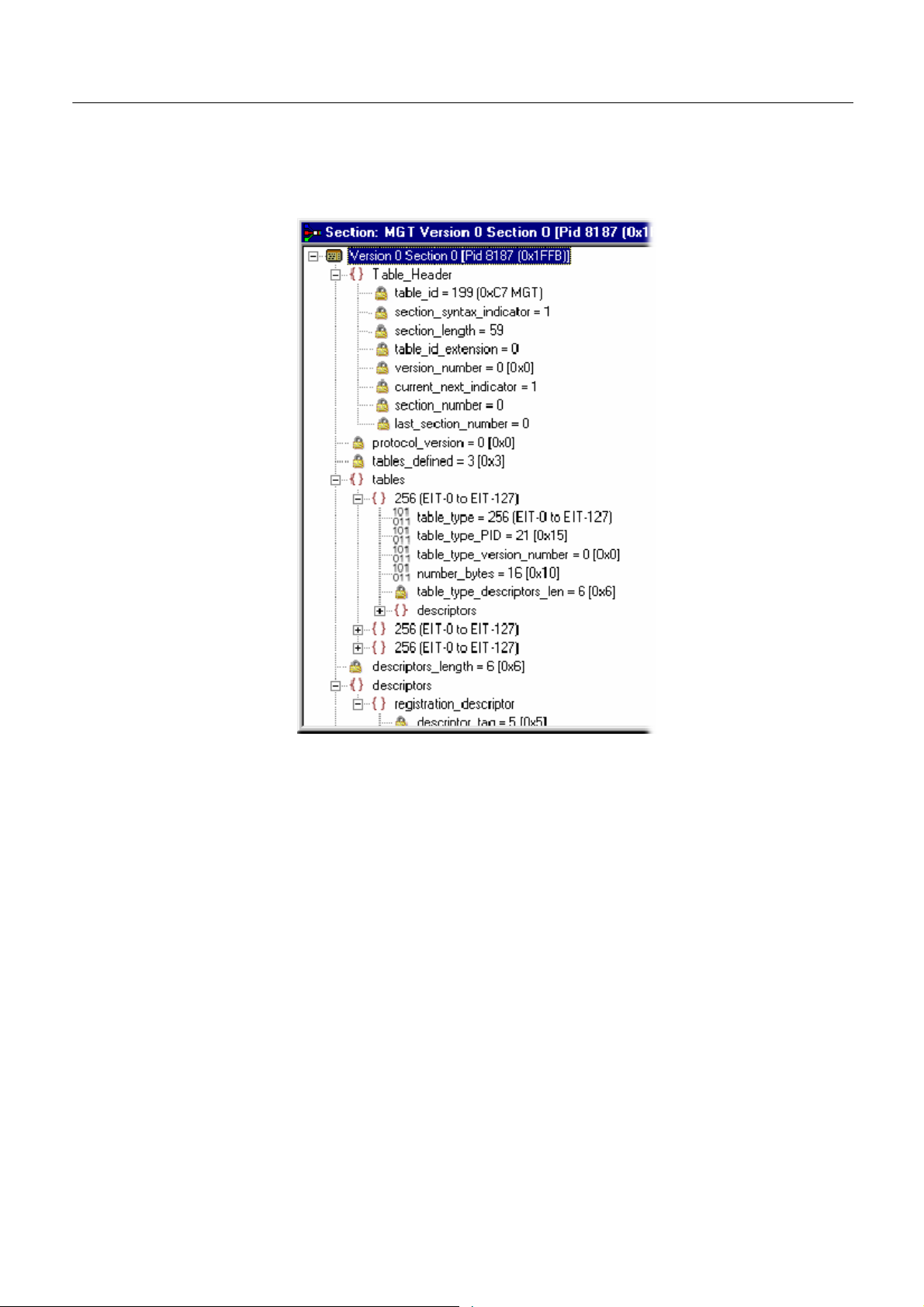
Syntax of a Section
The following diagram shows a section from a Master Guide Table (MGT).
60
The syntax specified for an MGT in the A TSC standard A65 is:
master_guide_table_section () {
table_id
section_syntax_indicator
private_indicator
zero
section_length
table_id_extension
reserved
version_number
current_next_indicator
section_number
last_section_number
protocol_version
tables_defined
for (i=0;i<tables_defined;i++) {
Multiplexer (Demo) User Manual
Page 69

table_type
reserved
table_type_PID
reserved
table_type_version_number
number_bytes
reserved
table_type_descriptors_length
for (k=0;k<N;k++)
descriptor()
}
reserved
descriptor tag
descriptors_length
for (I = 0;I< N;I++)
descriptor()
CRC_32
}
Multiplexer -- Views
The terms used in this manual to describe the components, represented by nodes,
in the structure diagram are:
Container A term used to describe a node in the structure diagram
which can contain zero, one or more loops. It is analogous to the for (i=0;i<loops_defined;i++) statement used
to describe the syntax of a table in the ATSC standards.
The container is always preceded by a field which specifies the number of loops it contains.
Loop Describes a data structure composed of a s pecified set of
fields and subordinate loops. The structure diagram
shows each loop as a node with the fields and subordinate loops as children. Each loop node in the section
view represents one iteration of the loop body (the contents of the curly braces { }) in the syntax specified by
the ATSC standards.
Field Fields are referred to in the standards documents as both
data items and fields. They are the smallest pieces of
information that make up a table.
Multiplexer (Demo) User Manual
61
Page 70

Multiplexer -- Views
Number of loops
For example, taking an MGT that defines three tables, the Section View
represents the syntax and contents of the Tables container like this:
Container
First loop
Second loop
Last loop
Contents
of the first
loop
Container for a
setofzeroor
more
The loop for the first table, EIT-0 has been expanded to show the fields and
subordinate loops that it contains.
62
Multiplexer (Demo) User Manual
Page 71
Multiplexer -- Views
Syntax of a Multiple String
Structure
The ATSC standard A65 defines a data structure called the Multiple String
Structure. An instance of this structure can contain zero or more strings and each
string can contain zero or more segments. The syntax specified for a Multiple
String Structure in A65 is:
multiple_string_structure () {
number_strings
for (i= 0;i< number_strings;i++) {
ISO_639_language_code
number_segments
for (j=0;j<number_segments;j++) {
compression_type
mode
number_bytes
for (k= 0;k<number_bytes;k++)
compressed_string_byte [k]
}
}
}
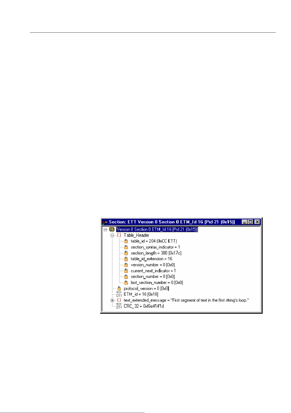
Using the notation of container, loop, and field nodes, Section View represents
the Multiple String Structure in the same way as any other data structure. For
example: an Extended Text Table (ETT) carries its extended_text_message in a
Multiple String Structure. The default view of a section of an ETT in the Section
View looks like this:
Multiplexer (Demo) User Manual
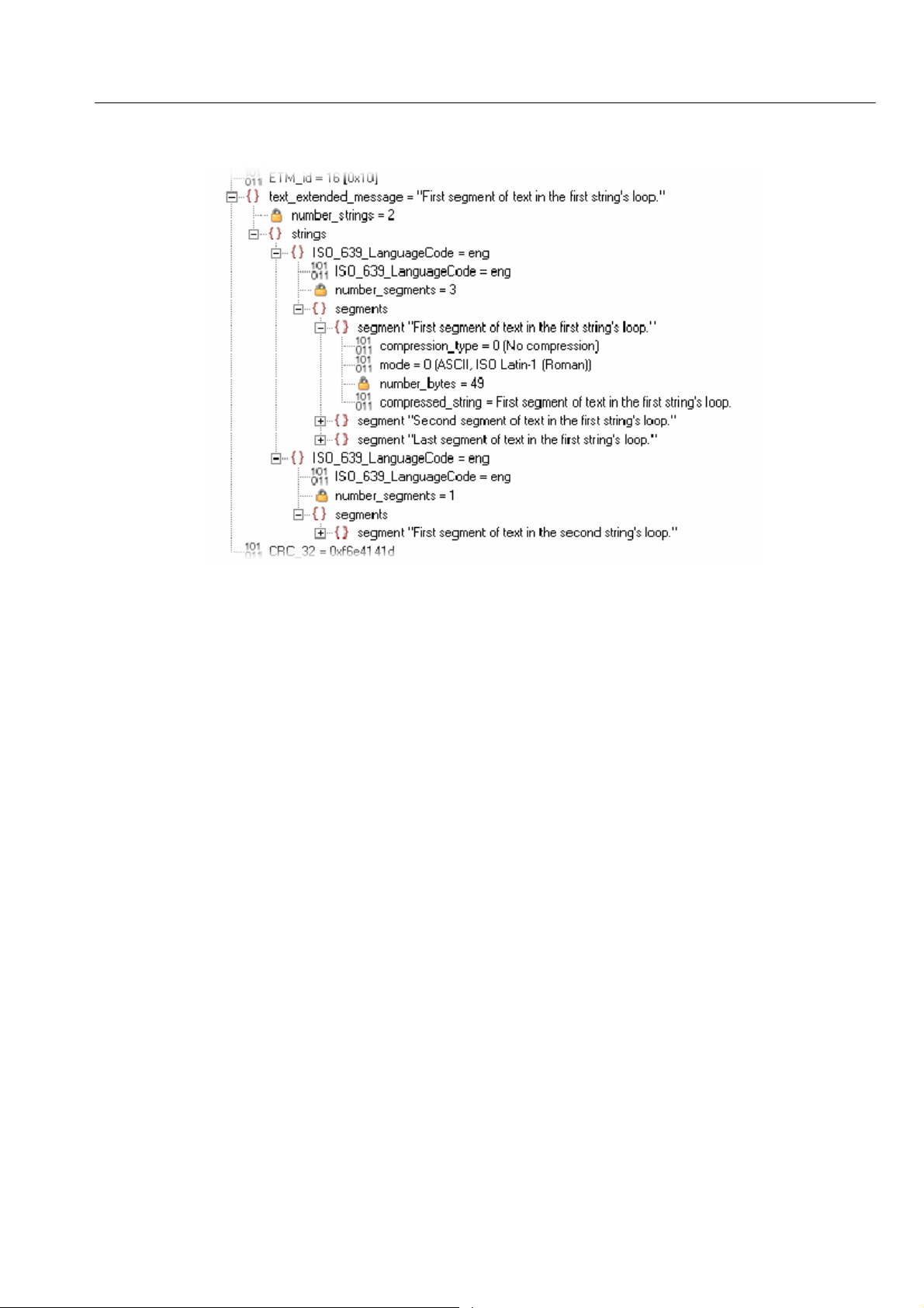
Section view displays a node for the extended_text_message with as much as
possible of t he first segment from the first string.
63
Page 72

Multiplexer -- Views
Expanding the node reveals a number_strings field which specifies the number
of strings and a container which holds them (strings):
The number_strings field shows that there are two strings in this example.
Expanding the strings container shows the loop for each string. From this it can
be seen that both strings are in English.
Expanding each of the strings reveals the number of segments (number_segments) that make up each string and a segments container. Similarly, expanding
the segments container reveals segments.
64
Multiplexer (Demo) User Manual
Page 73
Multiplexer -- Views
The contents of each segment loop define what compression and character set are
used, followed by the actual text. The text is held in the compressed_string field.
Multiplexer (Demo) User Manual
65
Page 74

Multiplexer -- Views
Expert and Standard
Modes
The Multiplexer has two modes of operation for conformance checking when
editing table contents. These are selected from the Multiplex menu. The checks
that affect the Navigator are:
Standard Mode Prevents changing the PID of a table whose PID number
is specified in the standard, for example, PID 0x0 carries
the PAT.
Expert Mode A warning is displayed and confirmation requested be-
fore changing the PID of a table whose PID number is
specified in the standard.
66
An adjacent check mark indicates the mode selected. The mode is also indicated
on the Status Bar.
Multiplexer (Demo) User Manual
Page 75

Multiplexer -- Views
In the Section View a padlock symbol
is displayed adjacent to all of the
fields that cannot be edited in the current mode. For example, the screens below
show the same tables in Standard and Expert mode.
Multiplexer (Demo) User Manual
Standard Mode Expert Mode
NOTE. The current_next_indicator in both Standard and Expert mode cannot be
edited. This is because the field is affected solely by the Section Properties
concerned with Version Timing (see Version Timing, page 100).
The selected mode is also reflected in the Wizards that are used to facilitate
creation of multiplexes. Elements that are restricted in the tables in Standard
mode will also be restricted in the relevant wizard. Similarly, elements that are
enabled in Expert mode will be enabled in the associated Wizard.
NOTE. The section view might need to be closed and reopened in order to update
the padlock icons.
67
Page 76

Multiplexer -- Views
Structure Diagram Manipulation
A tree diagram, with the “root node” or highest level component at the top
represents the Transport Structure. A square box indicates components that
contain more information beneath them in the structure.
Click on the box
to show or hide
the details
under the node.
68
Clicking on the box does not select that node. It only shows or hides the next
level of detail under that node.
If the node has a minus sign in the box the level of detail below it is currently
displayed. The lower level(s) can be hidden by clicking the mouse pointer on the
box.
If the box contains a plus sign, there is another level in the node that is currently
hidden. Click the mouse pointer on the box to display the next level of information under the node.
Components that are connected to a branch of the tree without a square box are
leaf nodes; the accompanying icon indicates the node type. They display the
lowest and finest level of detail available in this diagram. These are either a
SectionofaTableoraPID.
Multiplexer (Demo) User Manual
Page 77

Multiplexer -- Views
Fields in the Section view that cannot be edited directly are indicated by a
Event Log
padlock symbol,
Mode from the Multiplex menu. It can be reenabled by selecting Standard Mode.
Messages about significant events are written to the Event Log from the time a
file is first opened. The Event Log can be opened for viewing at any time during
or after the initial analysis. When the initial analysis is done, the mean transport
rate, bit rate for each PEES PID, and a Demultiplex complete message are
written in the Event Log.
The start and end times for generating a new transport stream are shown by the
Multiplexer started and Multiplexer completed messages.
. This protection can be switched off by selecting Expert
Note that when demultiplexing and multiplexing streams, the bit rate at which
the demultiplex or the multiplex is performed is given in the Event Log. This is
in addition to the stream bit rate derived from the stream itself.
When synthesizing a new transport stream any errors or warnings about the new
stream are written to the Event Log between the start and completed messages.
The Category column indicates the type of event. The subject or time of the
event is shown in the Reference column and the details are given in the
Comment column.
The complete text can be copied onto the Windows clipboard, using the Copy
option from the shortcut menu. The text can also be cleared with the Clear
command. Both commands are also available from the Edit menu.
Multiplexer (Demo) User Manual
69
Page 78

Multiplexer -- Views
Examine Transport Stream Window
The Examine Transport Stream (Examine TS) window (File > Examine TS)
performs two main functions within the Multiplexer:
H It allows you to take an overview of a transport stream before subjecting it to
full analysis.
H It allows tables and programs to be dragged and dropped from the examined
stream to the file that is currently open in Multiplexer.
Menu
Bar
File
Summary
Navigator
Views
70
Multiplexer (Demo) User Manual
Page 79

Multiplexer -- Views
Menu Bar
File Summary
The Examine TS window menu bar contains only two items: File and Edit.
File Menu. Table 13 lists the items in the File menu.
Table 13: Examine TS - File menu options
Command Function
Open... Analyzes and opens the selected file in the Examine TS
window. Closes the current file.
Close Closes the Examine TS window.
Edit Menu. Table 14 lists the items in the Edit menu.
Table 14: Examine TS - Edit menu options
Command Function
Copy Copies the currently highlighted section to the clipboard.
These fields provide a brief summary of the analyzed file.
Navigator Views
Filename The filename of the examined stream.
Interpretation The interpretation applied to the stream. This is the same
as that selected in the Multiplexer application through
the View menu: MPEG-2, DVB, ATSC, or ISDB.
TS Rate The transport stream bit rate derived from the stream.
Duration The duration of t he transport stream.
Status The status of the stream analysis.
The Examine TS Navigator views correspond to the Navigator views in the main
application. Programs, Tables, and PIDs are shown as they would be after a full
analysis. The PSI/SI tables are expanded and collapsed in the same manner. The
Section view is not available in the Examine TS window.
Multiplexer (Demo) User Manual
71
Page 80

Multiplexer -- Views
Examine TS Section Copy
While examining transport streams, it is possible to copy sections to the main
multiplex using the standard Windows techniques: copy and paste or by dragging
and dropping them with the aid of the mouse.
For example, to import a section that is visible in the Examine TS window into
the new multiplex configuration:
1. Select the Navigator Tables view.
2. Highlight the section to be copied in the Examine TS window and do one of
the following:
H Select Edit > Copy . With the Navigator Tables view active, select Edit >
Paste.
H Using the mouse, place the cursor over the highlighted section, press and
hold the left button on the mouse and drag the section onto the Navigator
Tables view. Release the mouse button.
3. Note that the copied section is placed in the PSI/SI structure at the correct
location. If any conflict arises concerning similar PID numbers, a new
version is created.
72
Multiplexer (Demo) User Manual
Page 81

SI Filtering
Multiplexer -- Views
Table elements can be excluded from the Navigator Tables view using the
Display Filter available through Options > Display F ilter.
The following dialog box is displayed:
Multiplexer (Demo) User Manual
73
Page 82
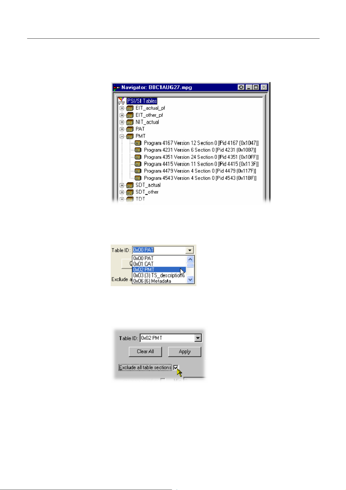
Multiplexer -- Views
Selecting a Table for
Filtering
Example: Before filtering, the stream tree might appear be as shown below:
In the F ilter SI Display dialog box, table identities are listed in the Table Id
drop-down menu.
74
All sections of a table can be excluded by enabling the Exclude all table sections
check box.
To preview the result of filtering, select the Apply button.
Note that all reference to the PMT tables is removed as shown below:
Multiplexer (Demo) User Manual
Page 83
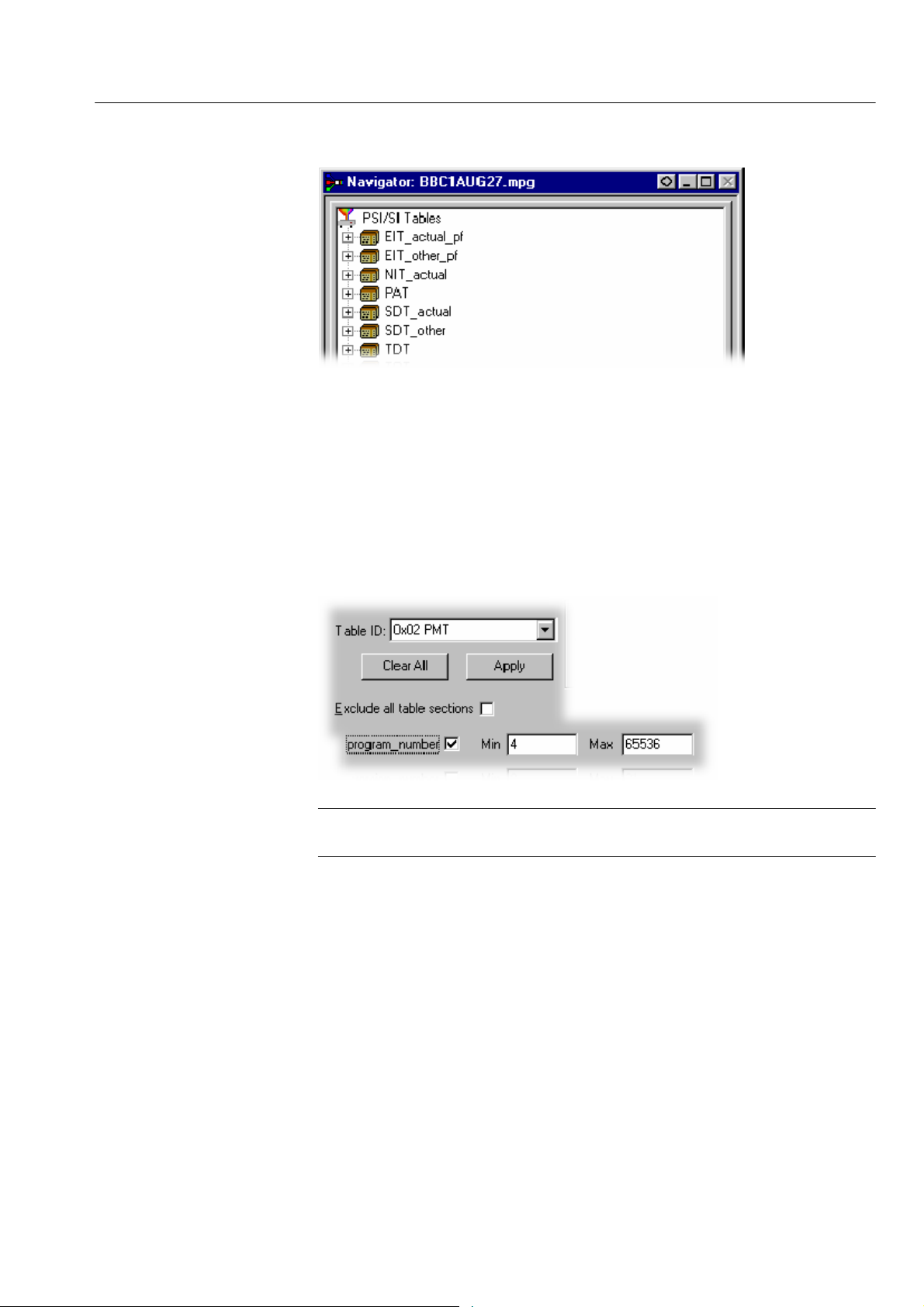
Multiplexer -- Views
To exclude a range of sections, enable the section by selecting from the Table ID
drop-down list and entering the required range.
Note that section names shown in the dialog box change according to which
table is selected.
To preview the result of filtering, select the Apply button.
For example, the following settings will result in the display shown overleaf:
NOTE. Minimum and maximum values can be entered in either decimal (12345)
or hexadecimal (0xA12B) format.
Multiplexer (Demo) User Manual
75
Page 84
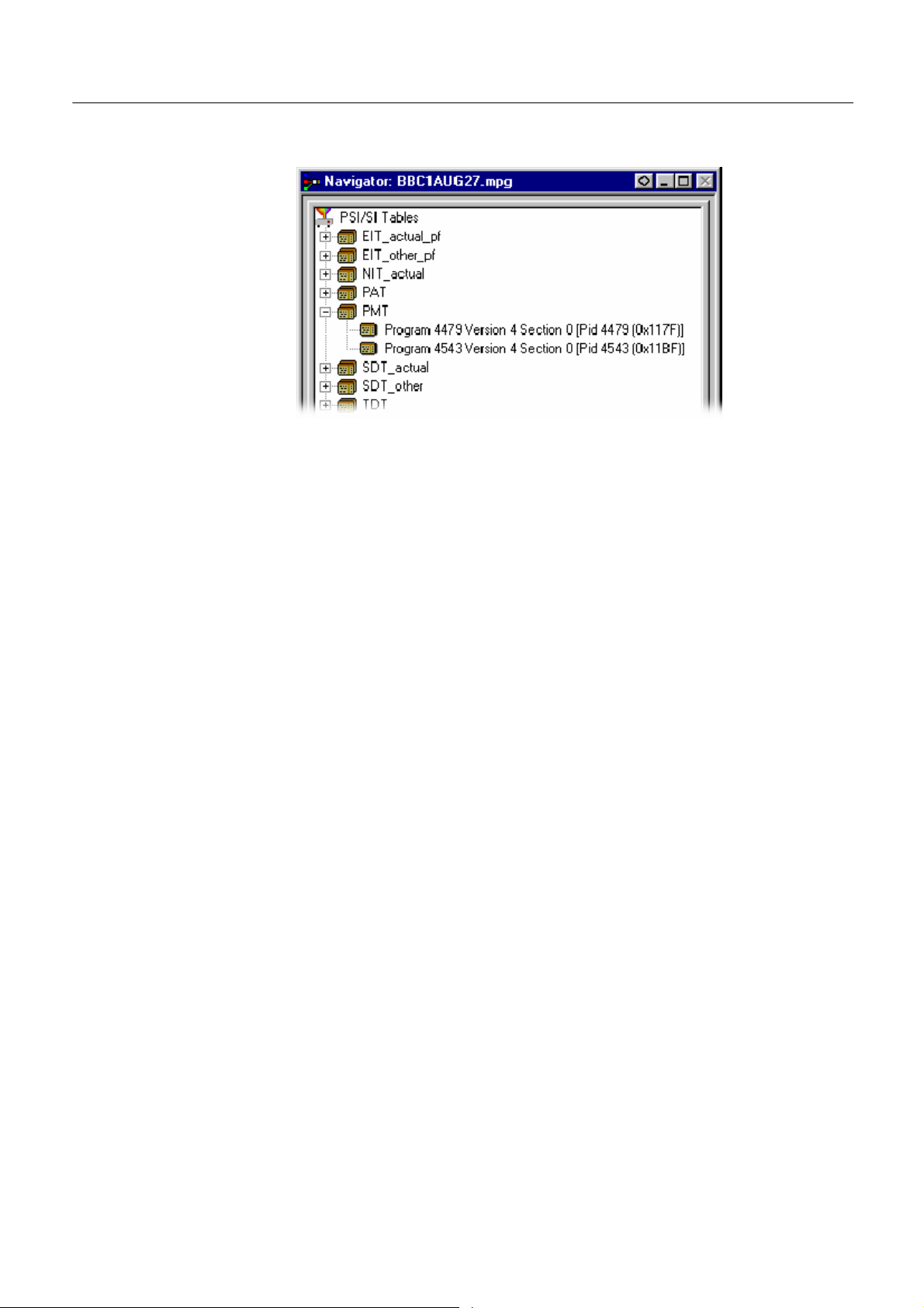
Multiplexer -- Views
The parameters for each table must be set individually. Overall settings can be
applied individually by selecting the Apply button when a setting is made or as a
whole by making all of the settings and selecting the OK button.
To preview the result of filtering, select the Apply button. All settings can be
cleared by selecting the Clear All button.
Saving/Loading SI Filter
Settings
Note that filter settings remain in force for as long as the current multiplex is
active. The settings are lost when the Multiplexer is closed unless they have been
previously saved.
The filter settings made in the Display Filter dialog box can be saved and
subsequently reapplied to the same stream or other streams.
To save the current filter settings, select the Save button and enter a name (and
location) in the Save As dialog box. To retrieve or load filter settings, select the
Load button and identify the filter file in the Open dialog box. The file extension
*.fil is used.
76
Multiplexer (Demo) User Manual
Page 85
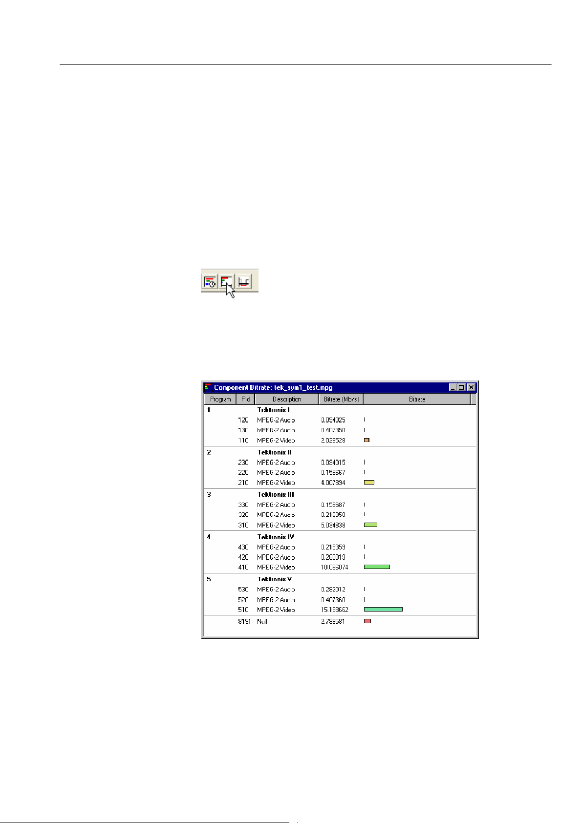
Component Views
Multiplexer -- Views
The Component views provide a graphical view of the bit rate and duration of
the components of a stream. The management of the views has a number of
common features; these are described in the Common Featur es, page 83.
Component Bit rate
The Component Bit rate view provides a graphical comparison of the stream
components.
Open the C omponent Bit rate view either by selecting View > Component Bit
rate from the Menu Bar or the toolbar button.
Each component includes the following information: Program name, PID,
Description and the Bit rate in numerical and graphical form. Where appropriate,
the Service ID and the Service Name is displayed (extracted from the SDT).
Component Duration
Multiplexer (Demo) User Manual
The Component Duration view provides a graphical view of the timing and
duration of each program/component within the current stream. Adjustments can
be made to the duration of each component.
77
Page 86

Multiplexer -- Views
Open the Component Duration view by selecting either View > Component
Duration from the Menu Bar or the toolbar button.
The following data is displayed for each component of the stream: Program,
Description, PID, Start and Stop time (in numerical and graphical form), Length
and Bit rate. The timing and bit rate elements of this information are also
available in the Program Stream Properties dialog box. (See Program Content
Dialog Box, page 43.)
78
Multiplexer (Demo) User Manual
Page 87
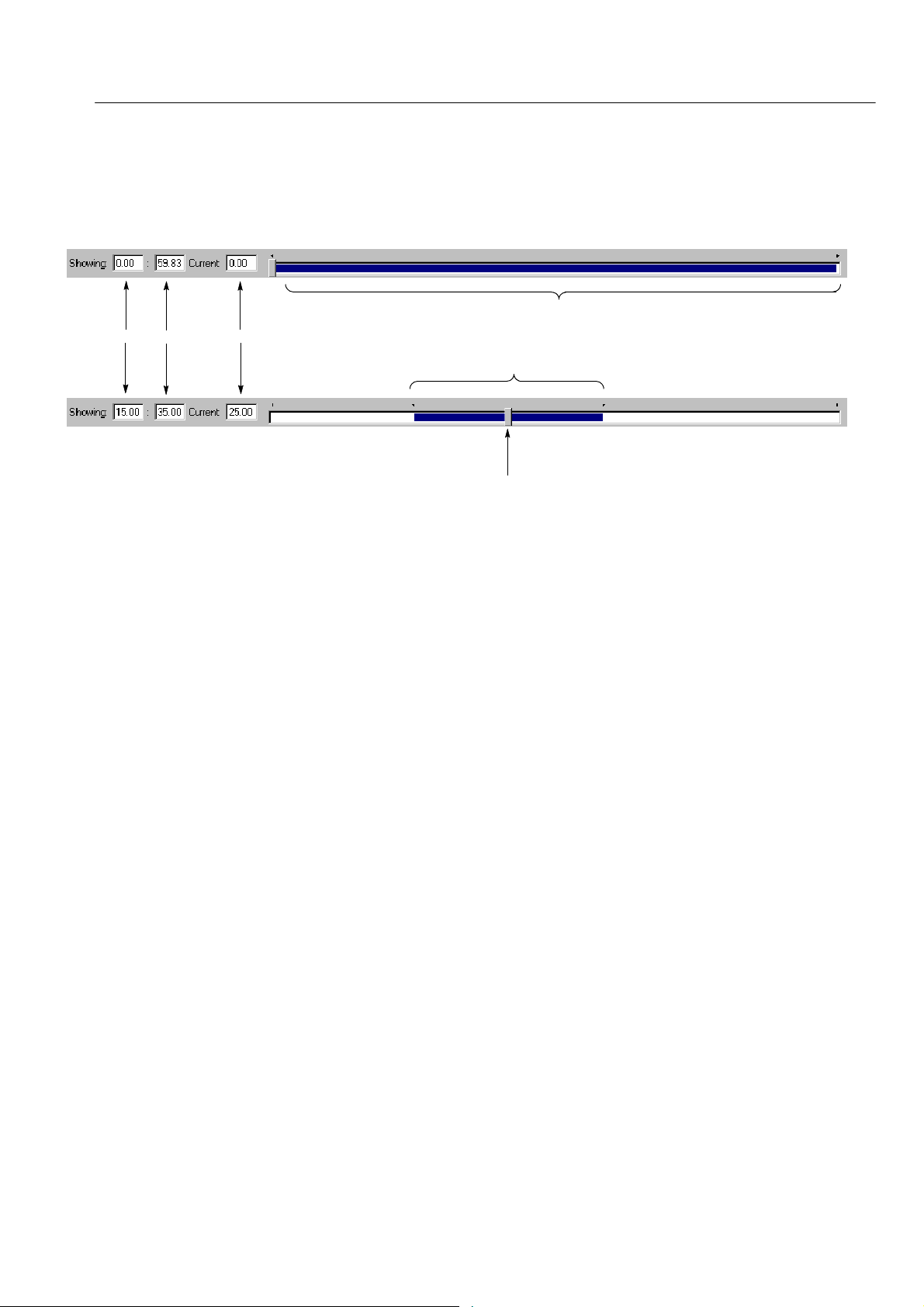
Multiplexer -- Views
Scaling Bar. The Scaling bar, which is displayed at the top of the Component
Duration view, allows you to select the portion of the transport stream that is to
be displayed.
(On opening)
Stream limits
Display
Limits
Pointer position
Display limits
(After
adjustment)
Pointer
The Stream limits bar represents the full extent of the stream. The Display limits
bar (dark portion) indicates the portion of the stream that is currently displayed
in the body of the view.
The Display limits fields indicate the extents of the Display limits bar and the
current Pointer position.
The P ointer can be dragged to a new position on the Stream limits bar. The
Display limits bar will center on the Pointer.
Multiplexer (Demo) User Manual
79
Page 88
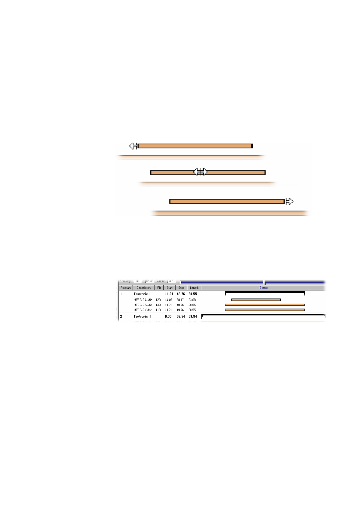
Multiplexer -- Views
Duration Control. The duration of each element in the stream is given by the Start
and Stop values and shown graphically by the associated bar. The components
are color coded according to which program group they belong to.
The Start, Stop and Length values can be changed by clicking on the appropriate
field and entering the required value. The associated bar will reflect the change.
The Start, Stop and Length values can also be changed graphically by manipulating the bar. The cursor shape indicates the action that can be taken.
The changes are reflected in the associated field values.
Components can be changed individually. In addition, whole Program groups
can be changed by manipulating the Program duration bar, but only when the
view is sorted by Program.
Program duration
A vertical dotted line indicates the upper limit of the multiplexed stream.
80
Multiplexer (Demo) User Manual
Page 89

Multiplexer -- Views
In the Transport Stream Properties dialog box (View > Properties with the
Transport Stream node highlighted in the Navigator Programs view), you can
determine how and if the stream duration i s updated. The available options will
be:
H Select Fixed to ensure that the stream duration can only be updated in the
Stream Properties dialog box.
H Select Set to the greatest component stop time to ensure that the stream
duration is set to the greatest stop time recorded in the SI/PSI/PSIP tables.
Component start and stop times changed in the Component Duration view are
automatically updated in the SI/PSI tables.
Multiplexer (Demo) User Manual
81
Page 90

Multiplexer -- Views
Available Bit rate
The Available Bit rate view displays in graphical form the available bit rate for
the duration of the multiplex.
The bit rate is calculated using the MGB2 measure (Ref: ETSI TR 101 290).
Open the Available Bit rate view by selecting View > Available Bit rate from the
Menu Bar or by using the toolbar button.
82
If the bit rate falls below zero, the points will be highlighted in red. When
editing a multiplex, you can add components which cause the bit rate to fall
below zero and no warnings will be displayed. However, if a transport stream is
then generated, errors will be logged and displayed in the Log view.
Use Refresh to redraw the graph. Clicking anywhere within the graph will place
a vertical cursor at that point; the position and bit rate are displayed in the Time
and Available Bit rate fields.
The zoom level and cursor placement of the Available Bit rate and the Component Duration views can be synchronized by selecting View > Synchronize.
Multiplexer (Demo) User Manual
Page 91

Multiplexer -- Views
Common Features
Columns in the Component views can be sorted and rearranged to suit your
preferences. Column management in the two Component views is similar.
Field Selection. You can select the fields to be displayed in each Component
view. The Header bar indicates which fields are currently displayed.
When you right-click on the Header bar, a menu is displayed. You can select
which fields are to be displayed. A check mark next to a field name indicates that
the field display is currently enabled.
The version number of the PAT and PMT can be displayed in the Description
column by enabling the Show program version option in the shortcut menu from
the Description column header.
Multiplexer (Demo) User Manual
Similarly, the PID numbers can be displayed in hexadecimal, by selecting
Display i n hexadecimal from t he P ID column shortcut menu.
83
Page 92

Multiplexer -- Views
Column Repositioning. Columns can be repositioned as required. Click and drag
the column to the required position.
Column Width. Columns can be resized as required. Place the cursor over the
dividing line between two columns; it will change to the resizing cursor. Click
and drag the column to the required width. The change will be made to the
column to the left of the cursor.
Double-clicking the column divider will automatically resize the column to the
left to the optimum size required t o view the content.
84
Multiplexer (Demo) User Manual
Page 93

Multiplexer -- Views
Column Sort. Columns can be sorted in ascending or descending order. Click the
cursor on the heading to sort the column. Clicking again will sort the column in
reverse order.
Similarly, the columns can be grouped in Program order, by clicking the
Program header.
Multiplexer (Demo) User Manual
85
Page 94

Multiplexer -- Views
Common Menu Options
The specifications for components of the various views can be manipulated by
options from the Edit menu, View Menu, and Toolbar.
There is also a shortcut menu that provides the Add, Modify, Delete, Import,
Export and Properties options. Place the mouse pointer over the component to
change and click the right mouse button to open the menu.
A typical shortcut menu is shown here:
The menu options are context-sensitive and will be enabled or disabled
according to the current selection in the view.
The following options are available from the various shortcut menus:
Add Adds a component to the currently selected item.
Modify Opens the properties dialog box.
Delete Deletes the currently selected component.
Properties Opens a properties dialog box for editing the
currently selected item.
Export Payload Extracts and exports the payload of the source
transport stream in the form of a simple data file.
Export Elementary
Stream
Export Section Data Extracts and exports section data. The created file
Import S ection Data Imports SI data form a file and analyzes it. The
Removes the transport stream and PES headers and
exports the remaining information in the form of a
simple data file.
can be imported as ES using Multiplexer’s Add
function or as SI using the Import Section Data...
option.
section is added to the Navigator view.
86
Multiplexer (Demo) User Manual
Page 95

Editing in the Navigator Views
Multiplexer provides a variety of ways of building and modifying transport
streams for multiplexing. In addition to the Menu Bar options and Toolbar
shortcuts built into the Multiplexer, many of the operations can be carried out
using familiar drag and drop Windows techniques.
In the following descriptions, the alternative methods for carrying out a task are
given at the head of the section, but only one method is described for each
action. Other methods for the same action often invoke the same dialog boxes
and s equence of follow-on actions.
Dragging and Dropping
To drag a file, click on its name and hold down the left button of the mouse
while dragging the file to the required location. The cursor will change according
to the background that it is dragged over:
(With Ctrl key held) when dropped, the file will
be copied.
When dropped, the file will be moved (cut and
pasted).
When dropped, no action will be taken.
Note that as the file is dragged over elements in the Navigator, receptive
elements (elements where the file can be meaningfully dropped) will be
highlighted.
Multiplexer (Demo) User Manual
87
Page 96
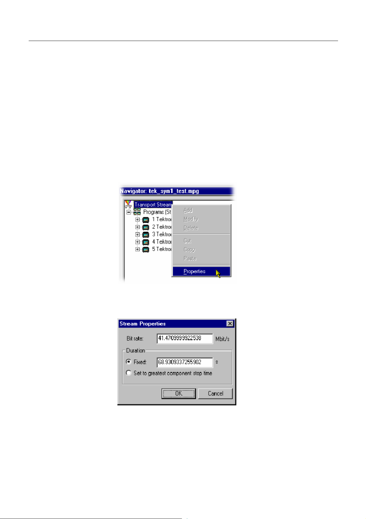
Multiplexer -- Editing in the Navigator Views
Transport Stream
Opening an MPEG File
Opening a Multiplexer File
Changing Transport
Stream Bit rate and
Duration
For information on Opening a Stream, refer to page 17.
For information on Opening a Stream, refer to page 17.
To specify a new bit rate or duration for the transport stream, select and highlight
the Transport Structure component in the Navigator view.
From the shortcut menu, select Properties. The dialog box shown below will be
displayed.
88
Edit the Bit rate and the Duration as required, then click on the OK button.
Multiplexer (Demo) User Manual
Page 97
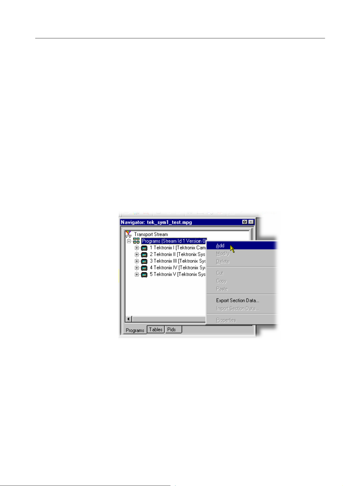
Programs
Multiplexer -- Editing in the Navigator Views
The introduction of the Navigator Programs view has provided a more programcentered means of manipulating S I/P SI. Whole programs can be added to the
multiplex and the application will update the associated tables, including the PAT
and PMT.
Note that the nodes of the tree structure in the Navigator Programs view are
context sensitive. When dragging and dropping files from either the Examine TS
window or from another instance of Multiplexer, a node will only be highlighted
as the cursor passes over it when the operation proposed is legal. There can be a
short delay before the node is highlighted, while the legality of the operation is
checked.
Adding a New Program
With the Transport Stream ID field highlighted in the Navigator Programs view,
selecting the Add option either from the shortcut menu (PAT highlighted in
Navigator Programs view) or the Menu Bar (Edit > Add) will open the P rogram
Wizard (see page 41).
Multiplexer (Demo) User Manual
In the Navigator Programs view, the PAT is represented by the Transport Stream
ID field.
89
Page 98

Multiplexer -- Editing in the Navigator Views
Copying/Moving a
Program
Methods available:
H Drag and drop (copy only) from the Examine TS window (Programs view)
to the Navigator Programs view.
H Drag and drop (copy/move) from another instance of Multiplexer to the
Navigator Programs view.
In the Navigator Programs view, programs can only be dropped onto the PAT
node.
90
Multiplexer (Demo) User Manual
Page 99
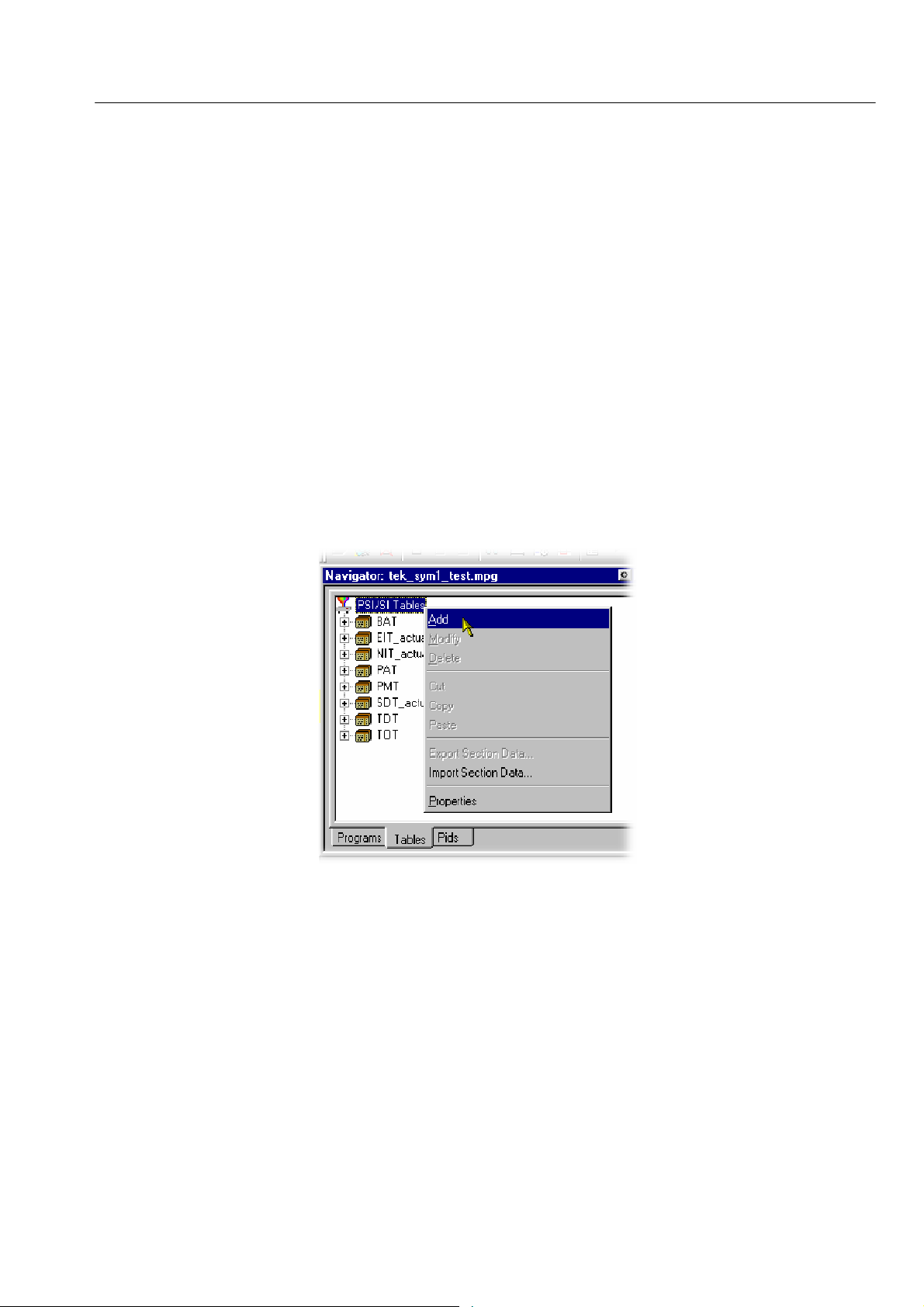
Tables
Multiplexer -- Editing in the Navigator Views
Adding a New PSI/SI Table
Methods available:
H Highlight the PSI/SI Tables level in the Navigator Tables view and select
Add from the shortcut menu.
H Drag and drop (copy only) from the Examine TS window (Tables view) to
the Navigator Tables view.
H Drag and drop (copy/move) from another instance of Multiplexer to the
Navigator Tables view.
Any Table that is defined in the selected standards, and not already present, can
be added the transport stream. To add a table to the transport stream, click on
PSI/SI Tables in the Navigator Tables view:
1. Highlight the PSI/SI Tables level and select Add from the shortcut menu.
Multiplexer (Demo) User Manual
91
Page 100

Multiplexer -- Editing in the Navigator Views
This will open the Select dialog box. The dialog box displays a list of the
table types that are not already present in the stream.
NOTE. A PAT table cannot be added when ISDB interpretation with Single
segment extension is selected.
2. Highlight the required table type and then select the OK button.
Pressing C ancel will abandon the operation without adding a new table.
Only the table types that are not currently specified for the stream are listed.
If the required table type is not listed, press the Cancel button to close the
dialog box without affecting the specification for the stream.
The Select PID & Table ID dialog box is displayed only if a PID and/or
Table ID need to be identified. Otherwise, the selected Table type is
automatically created.
92
Multiplexer (Demo) User Manual
 Loading...