

Page 1

User Manual
MTXS01
ISDB-T Transport Stream
Remultiplexing Software
071-1793-01
This document supports firmware version 4.1 and above.
www.tektronix.com
Page 2

Copyright © Tektronix, Inc. All rights reserved. Licensed software products are owned by Tektronix or its suppliers
and are protected by United States copyright laws and international treaty provisions.
Tektronix products are covered by U.S. and foreign patents, issued and pending. Information in this publication
supercedes that in all previously published material. Specifications and price change privileges reserved.
TEKTRONIX and TEK are registered trademarks of T ektronix, Inc.
Contacting Tektronix
T ektronix, Inc.
14200 SW Karl Braun Drive
P.O. Box 500
Beaverton, OR 97077
USA
For product information, sales, service, and technical suppo rt:
In North America, call 1-800-833-9200.
Worldwide, visit www.tektronix.com to find contacts in your area.
Page 3

Warranty 9(b)
Tektronix warrants that the media on which this software product is furnished and the encoding of the programs on the
media will be free from defects in materials and workmanship for a period of three (3) months from the date of
shipment. If any such medium or encoding proves defective during the warranty period, Tektronix will provide a
replacement in exchange for the defective medium. Except as to the media on which this software product is furnished,
this software product is provided “as is” without warranty of any kind, either express or implied. Tektronix does not
warrant that the functions contained in this software product will meet Customer’s requirements or that the operation
of the programs will be uninterrupted or error-free.
In order to obtain service under this warranty, Customer must notify Tektronix of the defect before the expiration of
the warranty period. If Tektronix is unable to provide a replacement that is free from defects in materials and
workmanship within a reasonable time thereafter, Customer may terminate the license for this software product and
return this software product and any associated materials for credit or refund.
THIS WARRANTY IS GIVEN BY TEKTRONIX WITH RESPECT TO THE PRODUCT IN LIEU OF ANY
OTHER WARRANTIES, EXPRESS OR IMPLIED. TEKTRONIX AND ITS VENDORS DISCLAIM ANY
IMPLIED WARRANTIES OF MERCHANTABILITY OR FITNESS FOR A PARTICULAR PURPOSE.
TEKTRONIX’ RESPONSIBILITY TO REPLACE DEFECTIVE MEDIA OR REFUND CUSTOMER’S
PAYMENT IS THE SOLE AND EXCLUSIVE REMEDY PROVIDED TO THE CUSTOMER FOR BREACH
OF THIS WARRANTY. TEKTRONIX AND ITS VENDORS WILL NOT BE LIABLE FOR ANY INDIRECT,
SPECIAL, INCIDENTAL, OR CONSEQUENTIAL DAMAGES IRRESPECTIVE OF WHETHER
TEKTRONIX OR THE VENDOR HAS ADVANCE NOTICE OF THE POSSIBILITY OF SUCH DAMAGES.
Page 4

Page 5

Table of Contents
Getting Started
Operating Basics
Appendices
Product Description . . . . . . . . . . . . . . . . . . . . . . . . . . . . . . . . . . . . . . . . . . . . . . . . . . . 1-1
Standard Accessories . . . . . . . . . . . . . . . . . . . . . . . . . . . . . . . . . . . . . . . . . . . . . . . . . . 1-1
Installing the MTXS01 Software. . . . . . . . . . . . . . . . . . . . . . . . . . . . . . . . . . . . . . . . . 1-2
Starting and Exiting the MTXS01 Software . . . . . . . . . . . . . . . . . . . . . . . . . . . . . . . . 1-5
Elements of the Application Window . . . . . . . . . . . . . . . . . . . . . . . . . . . . . . . . . . . . . 2-1
Using the MTXS01 Menus . . . . . . . . . . . . . . . . . . . . . . . . . . . . . . . . . . . . . . . . . . . . . 2-7
Creating an ISDB-T Transport Stream File . . . . . . . . . . . . . . . . . . . . . . . . . . . . . . . . 2-15
Outputting an ISDB-T Transport Stream File . . . . . . . . . . . . . . . . . . . . . . . . . . . . . . 2-16
Appendix A: Control Signal for the MTX100/A Option 02 . . . . . . . . . . . A-1
Appendix B: Transmission Control Information . . . . . . . . . . . . . . . . . . . B-1
Multiplexing to Dummy Byte Part. . . . . . . . . . . . . . . . . . . . . . . . . . . . . . . . . . . . . . . . B-1
Multiplexing to IIP. . . . . . . . . . . . . . . . . . . . . . . . . . . . . . . . . . . . . . . . . . . . . . . . . . . . B-2
Index
MTXS01 ISDB-T Transport S tream Remultiplexing Software User Manual i
Page 6

List of Figures
List of Figures
Figure 1-1: Software protection key . . . . . . . . . . . . . . . . . . . . . . . . . . . . . . 1-2
Figure 2-1: MTXS01 application window . . . . . . . . . . . . . . . . . . . . . . . . . . 2-1
Figure 2-2: Parameters setting area . . . . . . . . . . . . . . . . . . . . . . . . . . . . . . 2-2
Figure 2-3: Configuration of the hierarchy display . . . . . . . . . . . . . . . . . . 2-5
Figure 2-4: Open dialog box . . . . . . . . . . . . . . . . . . . . . . . . . . . . . . . . . . . . . 2-7
Figure 2-5: Load Parameter dialog box . . . . . . . . . . . . . . . . . . . . . . . . . . . 2-8
Figure 2-6: Reset Parameter dialog box . . . . . . . . . . . . . . . . . . . . . . . . . . . 2-9
Figure 2-7: Edit Data Rate dialog box . . . . . . . . . . . . . . . . . . . . . . . . . . . 2-10
Figure 2-8: Edit Information dialog box . . . . . . . . . . . . . . . . . . . . . . . . . . 2-10
Figure 2-9: Employment Parameter dialog box . . . . . . . . . . . . . . . . . . . . 2-11
Figure 2-10: Open Setting for no PAT TS dialog box . . . . . . . . . . . . . . . 2-14
Figure 2-11: Hierarchical view of the ISDB-T transport stream file . . . 2-17
Figure 2-12: ISDB-T Information dialog box . . . . . . . . . . . . . . . . . . . . . . 2-18
List of Tables
Figure A-1: Timing relationship of the signals on the Universal In/Out
connector . . . . . . . . . . . . . . . . . . . . . . . . . . . . . . . . . . . . . . . . . . . . . . . . . A-2
Table 2-1: Parameters for hierarchical transmission patterns . . . . . . . . 2-12
Table A-1: Pin assignment of the Universal In/Out connector . . . . . . . . A-1
Table B-1: Multiplexed information to dummy bytes . . . . . . . . . . . . . . . B-1
Table B-2: Configuration of the IIP packet . . . . . . . . . . . . . . . . . . . . . . . B-2
Table B-3: Configuration of modulation_control_configuration_
information . . . . . . . . . . . . . . . . . . . . . . . . . . . . . . . . . . . . . . . . . . . . . . . B-3
ii MTXS01 ISDB-T Transport Stream Remul tiplexing Software User Manual
Page 7

Getting Started
Page 8

Page 9

Getting Started
Product Description
This section provides the following information:
Product description
List of standard accessories
MTXS01 software installation instructions
MTXS01 software start and exit instructions
The MTXS01 software provides the capability to create a transport stream defined
in the ARIB STD-B31 “Transmission System for Digital Terrestrial Television
Broadcasting” standard from an MPEG-2 transport stream. The transport stream
that is remultiplexed by the MTXS01 software can be played from a Tektronix
MTX100/A MPEG Recorder & Player or RTX100/A ISDB-T RF Signal
Generator.
Requirements
Standard Accessories
NOTE. You can play a transport stream file created by the current version of the
MTXS01 software from the MTX100A/RTX100A, MTX100 with firmware version
2.0 or later, and RTX100 with firmware version 4.0 or later.
In the MTXS01 software, modulation parameter information is not inserted into SI
tables of a created transport stream file.
You can install the MTXS01 software on a Tektronix MTX100/A, RTX100/A, or
a PC with the following minimum requirements:
Windows XP/2000/NT operating system
CD-ROM drive (for software installation)
The following accessories are shipped with the MTXS01 software:
English User Manual (Option L0), Tektronix part number 071-1793-XX.
Japanese User Manual (Option L5), Tektronix part number 070-A861-XX
Software protection key, Tektronix part number 650-4922-00.
MTXS01 ISDB-T Transport S tream Remultiplexing Software User Manual 1-1
Page 10
Getting Started
Installing the MTXS01 Software
Perform the following steps to install the MTXS01 software on your MTX100/A,
R TX100/A, or PC:
Attaching the Software
Protection Key
Perform the following steps to attach the software protection key to the rear-panel
Printer port of the MTX100/A or RTX100/A, or to the parallel port of the PC
before using the MTXS01 software.
1. If there is a cable attached to the Printer port of the MTX100/A or RTX100/A,
or to the parallel port of the PC, disconnect the cable.
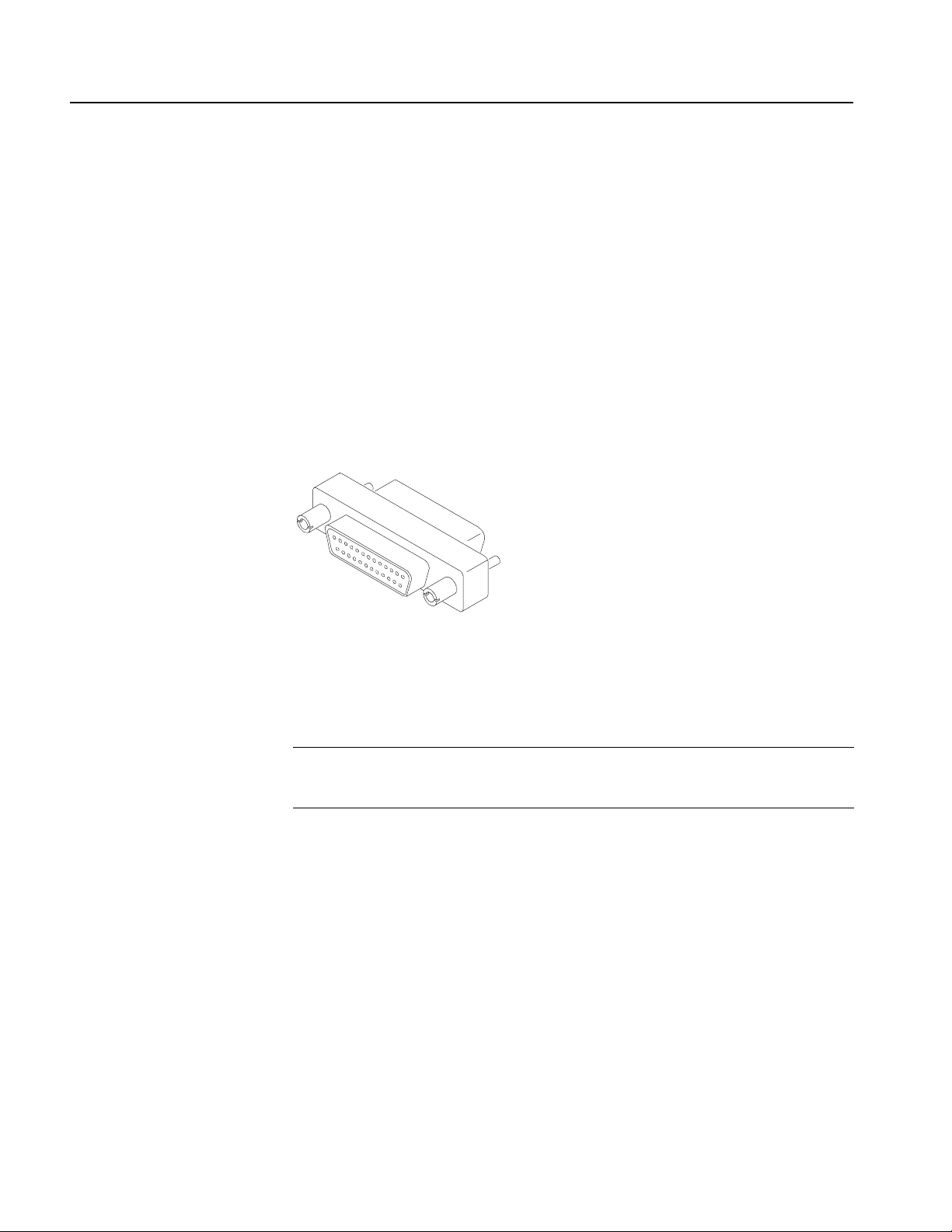
2. Attach the software protection key (see Figure 1-1) to the Printer port or
parallel port and tighten the retention screws.
Figure 1-1: Software protection key
3. If you removed a cable in step 1, reconnect it directly to the software protection
key.
NOTE. To run the MTXS01 software, the softwar e pr otection key must be installed
on the Printer port of the MTX100/A or RTX100/A, or on the parallel port of the
PC. Do not remove or misplace the software key.
Uninstalling the Existing
MTXS01 Software
1-2 MTXS01 ISDB-T Transport Stream Remul tiplexing Software User Manual
If an earlier version of the MTXS01 software is installed, perform the following
steps to uninstall the existing MTXS01 software:
1. For a MTX100/A or RTX100/A, select File > Exit in the Play or Record screen
to exit the MTX100/A or RTX100/A application. The Windows desktop
appears.
2. Select Settings > Control Panel from the Start menu. The Control panel
window appears.
3. Double-click the Add or Remove Programs icon. The Add or Remove
Programs Properties dialog box appears.
4. Select the ISDB-T Remux in the list, and then click the Remove button.
Page 11
5. After you remove the software, restart Windows.
Getting Started
Installing the Software
Perform the following steps to install the MTXS01 software:
1. For a MTX100/A or RTX100/A, select File > Exit in the Play or Record screen
to exit the MTX100/A or RTX100/A application. The Windows desktop
appears.
2. Log on to Windows as Administrator.
3. Insert the MTXS01 Version 4.1 CD-ROM into the CD-ROM (or DVD) drive.
4. Double-click the My Computer icon.
5. Double-click the CD-ROM (or DVD) drive icon.
6. Double-click the Application folder.
CAUTION. To prevent data loss, it is strongly r ecommended that you exit any open
application on your PC before you run the MTXS01 setup.exe file.
7. Double-click setup.exe icon in the list. The MTXS01 installation program
displays a series of setup windows as listed below. Click the Next> button to
accept the default parameters, or change the parameters in the setup windows
to suit your needs. Click the Back button in a setup window to return to the
previous setup window.
a. Welco me window. Read the displayed information, and then click the
Next button to proceed with the installation.
b. Choose Destination Location window. The default directory location for
the application is displayed. If you want to install the MTXS01 software in
a custom location, click the Browse... button, and then select or create a
custom directory location.
c. Select Program Folder window. The default name for the program folder
is displayed. If you want to change the name, type in a new name or select
a name from the Existing Folders list. Click the Next> button to proceed.
d. Start Copying Files window. Review the displayed information, and then
click the Next> button to start the installation.
e. Setup Complete window. If the installation is successful, you will see a
message that setup has finished installing the MTXS01 software onto your
PC. If you want to run the MTXS01 software immediately, se lect Yes,
Launch the program file, and then click the Finish button. To exit the
installation program without running the software, click the Finish button.
MTXS01 ISDB-T Transport S tream Remultiplexing Software User Manual 1-3
Page 12

Getting Started
Installing the Parallel
Driver
Creating a Desktop
Shortcut Icon
Perform the following steps to install the parallel driver:
1. Double-click the Driver folder in the MTXS01 Version 4.1 CD-ROM.
2. Double-click the SSD5411-32bit.EXE icon.
3. Click Next in the resulting window . The License Agr eement window appears.
4. Select I accept the terms in the license agreement, and then click Next. The
Destination Folder window appears.
5. Click Next. The Setup Type window appears.
6. Select Complete and click Next. The Ready to Install Program window
appears.
7. Click Install to proceed with installation.
8. When the InstallShield Wizard Completed window appears, click Finish to
complete the installation.
9. Remove the MTXS01 Version 4.1 CD-ROM from the CD-ROM (or DVD)
drive, and then store the CD-ROM in a safe location.
Perform the following steps to create an icon on the Windows desktop that you can
use to run the MTXS01 software:
1. On your Windows desktop, move the mouse cursor to any unoccupied area,
and then click the right mouse button to open the desktop menu.
2. From the desktop menu, select New > Shortcut to open the Create Shortcut
dialog box.
3. Click the Browse... button in the Create Shortcut dialog box.
4. Use the Browse dialog box to locate the ISDB-T Remux directory.
a. If you installed the MTXS01 software using the default directory location
and the default folder name in the installation procedure, select the
following directory folders in order: Program Files, Tektronix, and
ISDB-T_Remux.
b. If you installed the MTXS01software to a custom location or gave the
application folder a custom name, you will need to select your custom
directory path.
c. You should now be at a location in the directory structure where the
browse list box shows the ISDB-T_Remux.exe file.
1-4 MTXS01 ISDB-T Transport Stream Remul tiplexing Software User Manual
Page 13

5. Select the ISDB-T_Remux.exe file, and then click the Open button. The
directory path to the ISDB-T Remux.exe file will now be displayed in the
Command Line box of the Create Shortcut dialog box.
6. Click the Next> button in the Create Shortcut dialog box. The default name of
the shortcut icon is now displayed in the dialog box. You can edit the icon
name to suit your needs or accept the default name.
7. Click Finish. The ISDB-T_Remux.exe shortcut icon will appear on the
Windows desktop.
Starting and Exiting the MTXS01 Software
When you complete the installation procedure, you can use either of the following
methods to start the MTXS01 software:
On the W indows desktop, double-click the ISDB-T_Remux.exe shortcut icon
that you created during the installation procedure.
Getting Started
Select Tektronix > ISDB-T Remux from the Start - Programs menu.
To exit (quit) the MTXS01 software, select File > Exit or click the close box on
the title bar.
MTXS01 ISDB-T Transport S tream Remultiplexing Software User Manual 1-5
Page 14

Getting Started
1-6 MTXS01 ISDB-T Transport Stream Remul tiplexing Software User Manual
Page 15

Operating Basics
Page 16

Page 17

Operating Basics
This section provides the following information:
Elements of the application window
Using the MTXS01 menus
Creating an ISDB-T transport stream file
Outputting an ISDB-T transport stream file
Elements of the Application Window
Figure 2-1 shows the display elements of the MTXS01 application window.
Title bar
Menu bar
Current/Next tab
Para me te rs
setting area
Bit rate
display area
Remux Start button
Exit button
Cancel button
Hierarchy
display area
Layer change
buttons
Figure 2-1: MTXS01 application window
MTXS01 ISDB-T Transport S tream Remultiplexing Software User Manual 2-1
Page 18

Operating Basics
Title Bar
Menu Bar
Current/Next Tab
Parameters Setting Area
The title bar displays the name of the software. It also contains the standard
window-sizing boxes for Windows.
The menu bar displays the names of the pull-down menus. Refer to Using the
MTXS01 Menus on page 2-7 for detailed information about the functions available
in the menus.
Switches the Current parameters setting pane from/to Next parameters setting
pane. Use the Next parameters setting pane if you want to continuously output a
transport stream file that has a different modulation scheme than the first one. You
cannot set only parameters in the Next tab.
NOTE. Be sure to deselect the Regeneration PCR command in the Utility menu if
you set parameters in both Current and Next tabs.
When playing a remultiplexed transport str eam cr eated using the Current and Next
tabs from the MTX100/A or RTX100/A, disable the Update command in the Play
menu.
In the parameters setting area, there are fields to set transmission parameters for
remultiplexing a transport stream (see Figure 2-2).
Figure 2-2: Parameters setting area
2-2 MTXS01 ISDB-T Transport Stream Remul tiplexing Software User Manual
Page 19

Operating Basics
TS File: Specifies a transport stream file to be remultiplexed. To specify a
transport stream file, use the Open TS file command in the File menu or the
“...” button next to the text box.
Mode: Selects the transmission mode. You can select Mode 1, Mode 2, or
Mode 3.
Guard Interval: Selects the guard-interval ratio. You can select 1/32, 1/16,
1/8, or 1/4.
Partial Reception: Specifies whether or not partial reception is available in the
hierarchical layer A.
Modulation: Selects the carrier modulation scheme for each hierarchical layer .
You can select DQPSK, QPSK, 16QAM, or 64QAM.
Code Rate: Selects the inner-code coding rate for each hierarchical layer . You
can select 1/2, 2/3, 3/4, 5/6, or 7/8.
Time Interleaving: Selects the time interleaving length for each hierarchical
layer. Selectable values depend on the System Type setting in the Utility menu
and the transmission mode setting.
System Type setting Mode setting Selectable values
Digital TV Mode 1 0, 4, 8, 16
Mode 2 0, 2, 4, 8
Mode 3 0, 1, 2, 4
Digital Sound 3 Segment or
Digital Sound 1 Segment
Segment: Sets the number of OFDM segments for each hierarchical layer . The
Mode 1 0, 4, 8, 16, 32
Mode 2 0, 2, 4, 8, 16
Mode 3 0, 1, 2, 4, 8
values are determined as follows:
Hierarchical layer A: You can set the value from 1 to 13. If you set the Partial
Reception list box to ON, you cannot set values other than 1.
Hierarchical layer B: You can set the value less than or equal to 13–(setting
value of the hierarchical layer A). At this time, the number of segments for the
hierarchical layer C is set automatically; 13–(setting value of the hierarchical
layer A)–(setting value of the hierarchical layer B).
Hierarchical layer C: The value depends on the settings of the hierarchical
layers A and B.
MTXS01 ISDB-T Transport S tream Remultiplexing Software User Manual 2-3
Page 20

Operating Basics
Bit Rate Display Area
Displays the maximum and current bit rates of the selected transport stream. These
values are calculated by 188 bytes/packet.
Maximum: Displays the maximum bit rate calculated from the current
parameter settings.
Current: Displays the total information bit rate of the selected transport
stream.
NOTE. If the Current value is larger than the Maximum value, the background of
the Current field will turn red to indicate that you cannot perform any
remultiplexing proce ss under the current parameter settings.
If Partial Reception is set to ON, you may not perform any remultiplexing process
even if the Current value is smaller than the Maximum value.
If the time length of an elementary stream data is shorter than that of a transport
stream file, the Curr ent bit rate for the layer that has the elementary str eam data is
not displayed correctly (see the illustration below). In this case, if you r emultiplex
the file, relative time values of PCRs and PTS/DTSs in a created ISDB-T transport
stream file may become incorrect.
Transport stream file
Time
Acceptable:
Not acceptable:
Not acceptable:
Elementary stream data
Elementary stream data
Elementary stream data
Null
2-4 MTXS01 ISDB-T Transport Stream Remul tiplexing Software User Manual
Page 21

Operating Basics
Hierarchy Display Area
When you select a transport stream to be remultiplexed, a hierarchy display
appears in the right side of the application window. Figure 2-3 shows the
configuration of the hierarchy display.
Check box for changing
layer assignment
Component information
Component name
Hierarchical layer name
Figure 2-3: Configuration of the hierarchy display
Check Box for Changing Layer Assignment. Sets whether to change the hierarchical
layer for the transport stream component. When you select the check box, you can
change the hierarchical layer using buttons in the Check and Change Layer field.
Refer to Layer Change Buttons on page 2-6.
Hierarchical Layer Name. Shows the hierarchical layer name (A, B, or C) to which
the transport stream component is assigned. For PID and IIP (ISDB-T Information
Packet) that do not exist the packet, an x-indication is displayed instead of the
hierarchical layer name.
Component Name. Shows the name of the transport stream component.
Component Information. Shows information about the transport stream component
such as a packet ID or table ID.
The component information used in the MTXS01 software is common to the
information used in the MTX100/A and RTX100/A. For detailed information
about each transport stream component, refer to the User manual supplied with the
instrument.
MTXS01 ISDB-T Transport S tream Remultiplexing Software User Manual 2-5
Page 22

Operating Basics
Layer Change Buttons
By default, all of the transport stream components are assigned to the hierarchical
layer A. Y ou can change the lay er assignment for the components using the buttons
in the Check and Change Layer field.
A/B/C buttons: Changes the hierarchical layer of the transport stream
component that have a check mark to the hierarchical layer corresponding to
the button.
¢ button: Replaces the transport stream component that have a check mark
with a null packet.
ALL button: Selects all the check boxes of the transport stream components.
Clear button: Clears all the check boxes of the transport stream components.
Perform the following steps to change the hierarchical layer assignment for a
transport stream component:
1. Click the check box(es) of the component(s) for which you want to change the
hierarchical layer. If necessary, use the ALL or Clear button. You can select
check boxes by dragging a mouse on components with the left-mouse button
pressed. (If you drag a mouse on components with the right-mouse button
pressed, you can clear check boxes).
Remux Start Button
Cancel Button
2. Click the A, B, C, or ¢ button to change the assignment.
Y ou can also change the hierarchical layer assignment by clicking a layer name
on the hierarchy display. In this case, the layer name changes to A-B-C-¢ in
turn.
There are some restrictions on the hierarchical layer assignment for the transport
stream components:
You cannot assign the hierarchical layer that does not set the number of
segments.
If a PCR is included within a packet that has the same PID as the other
component, you cannot assign different hierarchical layers to the
components.
If there are two or more components that have the same PID, when you
change a hierarchy layer of a component, the other components are also
changed to the same hierarchical layer.
Starts the remultiplexing process.
Cancels the file loading or remultiplexing process.
2-6 MTXS01 ISDB-T Transport Stream Remul tiplexing Software User Manual
Page 23

Operating Basics
Exit Button
Exits the MTXS01 software.
Using the MTXS01 Menus
The menu bar displays the names of the four pull-down menus: File, Utility,
Remux, and Help. This section describes the function of each selection in these
menus.
File Menu
The File menu contains commands for managing file operation.
The commands are as follows:
Open TS File. Selects a transport stream file to be remultiplexed.
When you select File > Open TS File, the Open dialog box appears as shown in
Figure 2-4.
Figure 2-4: Open dialog box
Select the transport stream file you want to remultiplex in the file list and click the
Open button to open the file.
NOTE. For the selected transport stream to be recognized as a transport stream
file, sync bytes must be identified in five consecutive transport stream packets.
If a sync byte is identified in the middle of a transport stream file, the data before
the sync byte are invalid. In addition, the end of data that is less than 188 bytes is
invalid.
MTXS01 ISDB-T Transport S tream Remultiplexing Software User Manual 2-7
Page 24

Operating Basics
Close TS File. Closes the currently selected file.
Load Parameter.
Loads a saved parameter file (.prm) to use as the current settings.
When you select File > Load Parameter, and then you select a parameter file in
the Open dialog box, a dialog box appears as shown in Figure 2-5.
Figure 2-5: Load Parameter dialog box
If you click the “...” button at the right side of the text box, the Open dialog box
appears and you can select another parameter file.
NOTE. A parameter file (.prm) created by version 4.1 of the MTXS01 software
cannot be opened by earlier versions of the software.
Save Parameter. Saves the names of the transport stream files and their parameters
in the Current and Next tabs to a specified parameter file (.prm).
2-8 MTXS01 ISDB-T Transport Stream Remul tiplexing Software User Manual
Page 25

Operating Basics
Reset Parameter. Resets the current parameter settings to the default values.
When you select File > Reset Parameter, a dialog box appears as shown in
Figure 2-6.
Figure 2-6: Reset Parameter dialog box
Reset Current Parameter: Resets the parameters in the Current tab to the
default settings.
Utility Menu
Reset Next Parameter: Resets the parameters in the Next tab to the default
settings.
Reset Current & Next Parameter: Resets the parameters in the Current and
Next tabs to the default settings.
Minimize. Minimizes the MTXS01 application window.
Exit. Exits the MTXS01 software.
The Utility menu contains commands that select the digital broadcast type and set
the parameters needed for remultiplexing transmission control information.
The commands are as follows:
System Type. Specifies the terrestrial digital broadcasting type.
MTXS01 ISDB-T Transport S tream Remultiplexing Software User Manual 2-9
Page 26

Operating Basics
Edit Data Rate. Changes the data rate of the currently loaded transport stream file.
The data rate of the loaded transport stream file may be different from the actual
data rate because it is calculated based on PCRs in the file. In this case, you can
change the data rate using this command.
When you select Utility > Edit Data Rate, a dialog box appears as shown in Figure
2-7. If you change the data rate, the bit rate in the parameters setting area is also
changed.
Figure 2-7: Edit Data Rate dialog box
Current: Changes the data rate of the transport stream file in the Current tab.
Next: Changes the data rate of the transport stream file in the Next tab.
Edit Information. Sets parameters needed for remultiplexing transmitting control
information.
When you select Utility > Edit Information, a dialog box appears as shown in
Figure 2-8. The settings become available at the next remultiplexing process.
Figure 2-8: Edit Information dialog box
2-10 MTXS01 ISDB-T Transport Stream Remul tiplexing Software User Manual
Page 27

Operating Basics
Emergency Flag: Enables the start flag for emergency-alarm broadcasting.
IIP Packet PID: Specifies the PID of the ISDB-T information packet. The
default value is 0x1FF0.
Odd Number Frame: Selects how to process the last frame if the number of
multiplex frames are odd numbers. You can select Add dummy frame to the
end, Remove last frame, or As is.
Partial Reception PCR Interval: Sets the interval between PCR packets
when partial reception is specified in the hierarchical layer A.
Move the slider with the left mouse button pressed to set the interval time. The
value in the OFDM Frame box indicates the interval between frames that
include PCRs.
Employment Parameter. Sets the parameters for hierarchical transmission to the
hierarchical transmission patterns defined in ARIB TR-B14.
When you select Utility > Employment Parameter, a dialog box appears as
shown in Figure 2-9.
Figure 2-9: Employment Parameter dialog box
TR-B14 Service Pattern: Selects one of the hierarchical transmission
patterns.
MTXS01 ISDB-T Transport S tream Remultiplexing Software User Manual 2-11
Page 28

Operating Basics
T able 2-1 shows the parameters for hierarchical transmission patterns set by TR14
Service Pattern 1 to TR14 Service Pattern 6.
Table 2-1: Parameters for hierarchical transmission patterns
TR14 Service Pattern 1
Mode 3
Guard Interval 1/8
Partial Reception OFF
Layer ALayer BLayer C
Modulation 64QAM 64QAM 64QAM
Code Rate 3/4 3/4 3/4
Interleaving 2 2 2
Segment 13 0 0
TR14 Service Pattern 2
Mode 3
Guard Interval 1/8
Partial Reception OFF
Layer ALayer BLayer C
Modulation 16QAM 64QAM 64QAM
Code Rate 1/2 3/4 3/4
Interleaving 4 4 4
Segment 13 0 0
TR14 Service Pattern 3
Mode 3
Guard Interval 1/8
Partial Reception ON
Layer ALayer BLayer C
Modulation QPSK 64QAM 64QAM
Code Rate 1/2 3/4 3/4
Interleaving 4 4 4
Segment 1 12 0
TR14 Service Pattern 4
Mode 3
Guard Interval 1/8
Partial Reception OFF
Layer ALayer BLayer C
Modulation 16QAM 64QAM 64QAM
Code Rate 1/2 3/4 3/4
Interleaving 4 4 4
Segment 3 10 0
2-12 MTXS01 ISDB-T Transport Stream Remul tiplexing Software User Manual
Page 29

Operating Basics
Table 2-1: Parameters for hierarchical transmission patterns (cont.)
TR14 Service Pattern 5
Mode 3
Guard Interval 1/8
Partial Reception ON
Layer ALayer BLayer C
Modulation QPSK 16QAM 64QAM
Code Rate 1/2 1/2 3/4
Interleaving 4 4 4
Segment 1 12 0
TR14 Service Pattern 6
Mode 2
Guard Interval 1/4
Partial Reception OFF
Layer ALayer BLayer C
Modulation QPSK 16QAM 64QAM
Code Rate 1/2 1/2 3/4
Interleaving 2 2 2
Segment 1 3 9
Regenerated PCR. Selects whether to recalculate PCR values when remultiplexing
a transport stream.
NOTE. Be sure to clear the command if you have set the parameters in both Current
and Next tabs. In addition, if you play a remultiplexed transport stream created
using the Current and Next tabs from the MTX100/A or the RTX100/A, set the
Update command in the Play menu of the instrument to Off.
Duplicate Packet. Specifies whether to duplicate P AT , NIT , and CAT in null packets
in the hierarchical layer A when the following conditions are met:
1. Partial reception is specified in hierarchical layer A
.
2. Either the hierarchical layer B or C is the most robust layer.
3. PAT, NIT, or CAT is included in hierarchical layer B or C.
MTXS01 ISDB-T Transport S tream Remultiplexing Software User Manual 2-13
Page 30

Operating Basics
Open Setting for no PAT TS. Enables loading a transport stream that does not
contain any P A T s (Program Association T ables) by specifying PID values for PMT s
(Program Map Tables).
When you select Utility > Open Setting for no PAT TS, a dialog box appears as
shown in Figure 2-10.
Figure 2-10: Open Setting for no PAT TS dialog box
Automatically apply this data when no PAT was found in the stream:
Sets whether to load the transport stream by using the PMT PID values that are
specified in the dialog box when loading a transport stream that does not
contain any P ATs (if a transport stream contains any PAT, it is loaded using the
P AT). If you clear the check box, a transport stream that does not contain a P AT
cannot be loaded. By default, the check box is selected.
PMT PID: Specifies each PID value for PMTs in a transport stream to be
loaded. By default, the upper eight PID values are set to those that are allocated
by the ARIB TR-B14 standard. If you do not specify a PID value for a PMT, it
is not recognized as a PMT.
If you click the Advanced button, text boxes to set more PID values and program
numbers of PMT s are displayed. Use these text boxes to load PMTs with the same
PID value but a different program number . In addition, a text box to set a PID value
for an NIT (Network Information Table) is displayed. By default, it is set to
0x0010.
2-14 MTXS01 ISDB-T Transport Stream Remul tiplexing Software User Manual
Page 31

Operating Basics
Remux Menu
Help Menu
The Remux menu contains commands that start and cancel the remultiplexing
process.
The commands are as follows:
Start. Start the remultiplexing process.
Cancel. Cancels the remultiplexing process.
The Help menu contains command that display the version information about the
MTXS01 software.
About. Displays information including the software version number and copyright
information.
Creating an ISDB-T Transport Stream File
This section describes basic procedures for creating an ISDB-T transport stream
file from an MPEG-2 transport stream file.
1. Select File > Open TS File to open the Open dialog box.
2. Select the transport stream file you want to remultiplex, and then click the
Open button.
After the file is loaded, the “Analysis Complete” message appears.
3. Click the OK button in the dialog box.
4. Set the transmission parameter for remultiplexing the transport stream in the
parameters setting area.
a. Set the transmission mode in the Mode list box.
b. Set the guard interval ration in the Guard Interval list box.
c. Set the number of segments for hierarchical layers A and B in the Segment
list boxes.
d. Set whether or not partial reception is available in the hierarchical layer A
in the Partial Reception list box.
e. Set the carrier modulation scheme for each hierarchical layer in the
Modulation list boxes.
f. Set the inner-code coding rate for each hierarchical layer in the Code Rate
list boxes.
MTXS01 ISDB-T Transport S tream Remultiplexing Software User Manual 2-15
Page 32

Operating Basics
g. Set the time interleaving length for each hierarchical layer in the Time
Interleaving list boxes.
If you use the Employment Parameter command in the Utility menu, you
can set the parameters to the hierarchical transmission pattern defined in
ARIB TR-B14.
5. In the hierarchy display area, change the hierarchical layer assignment (A, B,
C, or, ¢) for transport stream components (refer to Layer Change Buttons on
page 2-6).
6. If necessary, click the Next tab and repeat steps 1 through 5 to set the
parameters.
7. Select Utility > Edit Data Rate to open the Edit Data Rate dialog box.
8. In the dialog box, change the data rate of the selected transport stream.
9. Select Utility > Edit Information to open the Edit Information dialog box.
10. In the dialog box, set the parameters needed for remultiplexing transmitting
control information.
11. When you set the all the parameters, click the Remux Start button or select
Remux > Start. The Save As dialog box appears.
12. Enter a file name in the File name text box (if you do not use the default file
name).
13. Click the Save button.
This creates a transport stream file defined in the ARIB STD-B31 standard.
Outputting an ISDB-T Transport Stream File
This section describes how to output an ISDB-T transport stream file from the
MTX100/A or RTX100/A.
NOTE. The MTX100/A Option 02 has differ en t pull-down menu configur ation and
pin assignment of the Universal In/Out connector when outputting an ISDB-T
transport stream file.
1. Press the front-panel PLAY button to display the Play screen (if not displayed).
2. Select File > Open to open the Select File dialog box.
3. In the dialog box, select the ISDB-T transport stream file (.rmx) you want to
output.
2-16 MTXS01 ISDB-T Transport Stream Remul tiplexing Software User Manual
Page 33

Operating Basics
The hierarchical view of the selected file is displayed on the screen as shown
in Figure 2-11.
NOTE. The ISDB-T transport str eam is differ ent fr om the typical transport str eam,
so the icon is not represented as a train.
Figure 2-11: Hierarchical view of the ISDB-T transport stream file
MTXS01 ISDB-T Transport S tream Remultiplexing Software User Manual 2-17
Page 34

Operating Basics
4. Select the ISDB-T transport stream icon and press the front-panel SELECT
button (or click the icon with the right mouse button) to open the ISDB-T
Information dialog box shown in Figure 2-12.
Figure 2-12: ISDB-T Information dialog box
Use this dialog box to check the transmission parameters of the ISDB-T
transport stream.
For the MTX100/A (other than Option 02) or RTX100/A:
5. Use an interface cable to connect the SPI In/Out connector (or the output
connector on the installed option card) on the MTX100/A or the RTX100/A
and an ISDB-T modulator.
6. Press the PLAY button on the MTX100 /A or RTX100/A to output the transport
stream.
For the MTX100/A Option 02:
7. Use an interface cable to connect the SPI In/Out connector on the MTX100/A
Option 02 and the TSP input on the ISDB-T modulator.
8. Use an interface cable to connect the Universal In/Out connector on the
MTX100/A Option 02 and the PI input on the ISDB-T modulator.
9. Select Univ I/F > PI Clock. This menu item is available only when an ISDB-T
transport stream file is loaded.
10. In the displayed submenu, select the scale factor of the Packet Information
clock to the TS clock (4 MHz).
2-18 MTXS01 ISDB-T Transport Stream Remul tiplexing Software User Manual
Page 35

Operating Basics
11. In the Univ I/F menu on the MTX100/A Option 02, make the following
settings:
Level. . . . . . . . LVDS
Format . . . . . . Parallel
Clock . . . . . . . Rise
12. Press the PLAY button on the MTX100/A Option 02 to output the transport
stream.
At this time, the transport stream data is output from the SPI In/Out connector
and control signals for the hierarchical multiplexing parameters are output
from the Universal In/Out connector.
Refer to Appendix A: Control Signals for the MTX100/A Option 02 for
information about the pin assignments of the Universal In/Out connector and
timing relationship of the output signals on the connector.
MTXS01 ISDB-T Transport S tream Remultiplexing Software User Manual 2-19
Page 36

Operating Basics
2-20 MTXS01 ISDB-T Transport Stream Remul tiplexing Software User Manual
Page 37

Appendices
Page 38

Page 39

Appendix A: Control Signal for the MTX100/A Option 02
For the MTX100/A Option 02, the control signals for the hierarchical multiplexing
parameters are output from the Universal In/Out connector when outputting an
ISDB-T transport stream.
This appendix describes the pin assignments of the Universal In/Out connector
when the control signals are output and shows the timing relationship of these
signals.
Table A-1 lists the pin assignment of the Universal In/Out connector.
Table A-1: Pin assignment of the Universal In/Out connector
Characteristics Description
Universal In/Out connector
Connect type D-sub, 25 pin
Pin assignment 1Clock
2GND 15GND
3CD3 16CD3
4CD2 17CD2
5CD1 18CD1
6CD0 19CD0
7 HFLAG3 20 HFLAG3
8 HFLAG2 21 HFLAG2
9 HFLAG1 22 HFLAG1
10 HFLAG0 23 HFLAG1
11 NC 24 NC
12 Frame 25 Frame
13 GND
1
14 Clock
1 The clock frequency can be selected from 4 MHz, 8 MHz, 16 MHz, or 32 MHz using the PI Clock command in the Univ I/F
menu.
MTXS01 ISDB-T Transport S tream Remultiplexing Software User Manual A-1
Page 40

Appendix A: Control Signal for the MTX100/A Option 02
Figure A-1 shows the timing relationship of the signals on the Universal In/Out
connector.
CD[0-3]
Data[0-7]
(packet unit)
HFLAG0
HFLAG1
HFLAG2
Frame
Data[0-7]
(byte unit)
TS-Clock
Psync
Dvalid
FFFED FFFF543210
Count-down period of the transmission
parameters change indicator
1 frame
L: fixed
1 frame
(Duty 50% ± 0.5%)
1 TSP (204 bytes)
Figure A-1: Timing relationship of the signals on the Universal In/Out connector
A-2 MTXS01 ISDB-T Transport Stream Remul tiplexing Software User Manual
Page 41

Appendix B: Transmission Control Information
This appendix describes transmission control information multiplexed to a
transport stream according as the ARIB STD-B31 5.5 standard.
Multiplexing to Dummy Byte Part
Table B-1 lists transmission control information multiplexed to dummy byte part
of each transport steam packet (189 byte to 196 byte). Some of the information uses
values set in the Edit Information dialog box in the Utility menu.
Table B-1: Multiplexed information to dummy bytes
Byte Bit Syntax Description
0(189) 7
6= 0= 1
5 reserved “1”
4 buffer_reset_control_flag “0”
3 switch-on_control_for_emergency_
2 initialization_timing_head_packet_flag Start packet after changing a transmission parameter: “1”
1 frame_head_packet_flag The multiplex frame head packet: ”1”
0 frame_indicator During even frame of the OFDM frame: “0”
1(190) 7-4 layer_indicator “0000”: dummy packet
3-0 count_down_index “1111”: Normally
2(191) 7 AC_data_invalid_flag “1”
6-5 AC_data_effective_bytes All “1”
4-0
3(192) 7-0
TMCC_identifier
broadcasting
TSP_counter
= 1
Terrestrial digital TV
Set in the Edit Information dialog box.
Normally: “0”
Normally: “0”
During odd frame of the OFDM frame: “1”
“0001”: packet transmitted by hierarchical layer A
“0010”: packet transmitted by hierarchical layer B
“0011”: packet transmitted by hierarchical layer C
“1000”: ISDB-T information packet (IIP)
“1110”: 15 frames before switching
“1101”: 14 frames before switching
:
“0001”: 2 frames before switching
“0000”: 1 frame before switching
A counter in which the head packet of the multiplex frame is 0
and increments one by one in order of packet.
= 1
Terrestrial digital audio
MTXS01 ISDB-T Transport S tream Remultiplexing Software User Manual B-1
Page 42

Appendix B: Transmission Control Information
Table B-1: Multiplexed information to dummy bytes (cont.)
Byte Bit Syntax Description
4(193) 7-0 AC_data All “1”
5(194) 7-0 AC_data All “1”
6(195) 7-0 AC_data All “1”
7(196) 7-0 AC_data All “1”
Multiplexing to IIP
Information except for Table B-1 is added to invalid hierarchy IIP (ISDB-T
_Information_Packet), and the packet is replaced with one dummy packet in a
multiplex frame. Some of the information uses values set in the Edit Information
dialog box in the Utility menu. T able B-2 shows the configuration of the IIP packet.
Table B-2: Configuration of the IIP packet
Syntax Description Number of bits
sync_byte synchronization byte: 0x47 8
transport_error_indicator Always “0” 1
payload_unit_start_indicator Always “1” 1
transport_priority Always “0” 1
PID The value is set in the Edit Information dialog box.
Default value: 0x1FF0
transport_scrambling_control Always “00” 2
adaptation_field_control Always “01” 2
continuity_counter The value is increased with each transport stream packet. It
wraps around to 0 after its maximum value (0x1111).
IIP_packet_pointer The number of packets from the multiplex position to the next
multiplex frame head in the multiplex frame of the IIP.
modulation_control_configuration_information See Table B-3. 160
IIP_branch_number Always “0x00” 8
last_IIP_branch_number Always “0x00” 8
network_synchronization_information_length Always “0x00” (no SFN information) 8
stuffing_byte (0XFF) 159 (188-29) bytes 0xFF 8X159
13
4
16
B-2 MTXS01 ISDB-T Transport Stream Remul tiplexing Software User Manual
Page 43

Appendix B: Transmission Control Information
Table B-3 shows the configuration of modulated_control_configuration_
information.
Table B-3: Configuration of modulation_control_configuration_information
Syntax Description Number of bits
TMCC_syncronization_word Even frame: “0”
Odd frame: “1”
AC_data_effective_position “1” 1
reserved All “1” 2
initialization_timing_indicator Switching timing of mode and guard interval ratio 4
current_mode Current Mode value
00: reserved, 01: Mode 1, 10: Mode 2, 11: Mode 3
current_guard_interval Current guard interval ratio
00: 1/32, 01: 1/16, 10: 1/8,11: 1/4
next_mode Next mode value 2
next_guard_interval Next guard interval ratio 2
system_indicator 00: Terrestrial digital TV, 01: Terrestrial digital audio 2
count_down_index Transmission parameter switching index 4
switch-on_control_flag_used_for_alert_broadcasting The value is set in the Edit Information dialog box. 1
current_configuration_information The following current information: (40)
partial_reception_flag Digital TV = partial reception flag
0: without partial reception, 1: with partial reception
Digital sound = system identification flag
0: 1 segment system, 1: 3 segment system
transmission_parameter_for_layer_A The following transmission-parameter information for
hierarchical layer A:
modulation_scheme Carrier modulation scheme
000: DQPSK, 001: QPSK, 010: 16 QAM, 011: 64 QAM,
111: unused hierarchical layer
coding_rate_of_inner_code Convolution coding ratio
000: 1/2, 001: 2/3, 010: 3/4, 011: 5/6, 100: 7/8,
111: unused hierarchical layer
length_of_time_interleaving Time interleaving length
000: 0 (Mode 1), 0 (Mode 2), 0 (Mode 3)
001: 4 (Mode1), 2 (Mode 2),1 (Mode 3)
010: 8 (Mode 1), 4 (Mode 2), 2 (Mode 3)
011: 16 (Mode 1), 8 (Mode 2), 4 (Mode 3)
100: 32 (Mode 1), 16 (Mode 2), 8 (Mode 3)
101-110: reserved
111: unused layer
number_of _segments Number of segments
0001-1101: 1 to 13, 1111: unused hierarchical layer
transmission_parameter_for_layer_B Transmission parameter information for hierarchical layer B
(same as layer A)
1
2
2
1
(13)
3
3
3
4
(13)
MTXS01 ISDB-T Transport S tream Remultiplexing Software User Manual B-3
Page 44

Appendix B: Transmission Control Information
Table B-3: Configuration of modulation_control_configuration_information (cont.)
Syntax Description Number of bits
transmission_parameter_for_layer_C Transmission parameter information for hierarchical layer C
(same as layer A)
next_configuration_information Next information (same as the current information) (40)
phase_correction_of_CP_in_connected_
transmission
TMCC_reserved_future_use All “1” 12
reserved_future_use All “1” 10
CRC_32 CRC value from TMCC_syncronization_word to
All “1” 3
reserved_future_use
(13)
32
B-4 MTXS01 ISDB-T Transport Stream Remul tiplexing Software User Manual
Page 45

Index
Page 46

Page 47

Index
A
A/B/C/X buttons, 2-6
ALL button, 2-6
Application window, 2-1
ARIB TR-B14, 2-11
C
Cancel button, 2-6
Clear button, 2-6
Close TS File command, 2-8
Code rate, 2-3
Current tab, 2-2
D
Duplicate Packet command, 2-13
E
Edit Data Rate command, 2-10
Edit Data Rate dialog box, 2-10
Edit Information command, 2-10
Edit Information dialog box, 2-10
Employment Parameter command, 2-11
Employment Parameter dialog box, 2-11
Exit button, 2-7
Exit command, 2-9
Exit, MTXS01 software, 1-5
I
IIP, B-2
Install, MTXS01 software, 1-3
Install, parallel driver, 1-4
L
Load Parameter command, 2-8
Load Parameter dialog box, 2-8
M
Menu bar, 2-2
Minimize command, 2-9
N
Next tab, 2-2
O
Open Setting for no PAT TS command, 2-14
Open Setting for no PAT TS dialog box, 2-14
Open TS File command, 2-7
P
Partial reception, 2-3
F
File menu, 2-7
Product description, 1-1
R
G
Guard interval, 2-3
Regenerate PCR command, 2-13
Remux menu, 2-15
Remux Start button, 2-6
Requirements, PC, 1-1
Reset Parameter command, 2-9
Reset Parameter dialog box, 2-9
H
Help menu, 2-15
Hierarchical transmission patterns, 2-12
MTXS01 ISDB-T Transport S tream Remultiplexing Software User Manual Index-1
S
Save Parameter command, 2-8
Software installation, 1-3
Software protection key, 1-2
Page 48

Index
Standard accessories, 1-1
Start, MTXS01 software, 1-5
System Type command, 2-9
T
Time interleaving , 2-3
Title bar, 2-2
U
Utility menu, 2-9
Index-2 MTXS01 ISDB-T Transport Stream Remultiplexing Software User Manual
 Loading...