


MTSA-HW and MTSA-PC
MPEG Test Systems
Quick Start User Manual
*P071366100*
071-3661-00


MTSA-HW and MTSA-PC
MPEG Test Systems
Quick Start User Manual
Warning
The servicing instructions are for use by qualified personnel only. To avoid
personal injury, do not perform any servicing unless you are qualified to do
so. Refer to all safety summaries prior to performing service.
Supports MTSA firmware v3.3.1 and above.
www.tek.com
071-3661-00

Copyright © Tektronix. All rights reserved. Licensed software products are owned by Tektronix or its subsidiaries or suppliers, and are
protected by national copyright laws and international treaty provisions. Tektronix products are covered by U.S. and foreign patents, issued
and pending. Information in this publication supersedes that in all previously published material. Specifications and price change privileges
reserved.
TEKTRONIX and TEK are registered trademarks of Tektronix, Inc.
CaptureVu and FlexVu Plus are registered trademarks of Tektronix, Inc.
Contacting Tektronix
Tektronix, Inc.
14150 SW Karl Braun Drive
P.O. Box 500
Beaverton, OR 97077
USA
For product information, sales, service, and technical support:
■
In North America, call 1-800-833-9200.
■
Worldwide, visit www.tek.com to find contacts in your area.

Table of Contents
Important safety information ................................................................................................................................ iii
General safety summary ................................................................................................................................ iii
Service safety summary ................................................................................................................................ iv
Terms in the manual ....................................................................................................................................... v
Terms on the product ..................................................................................................................................... v
Symbols on the product .................................................................................................................................. v
Compliance Information ...................................................................................................................................... vii
EMC compliance ........................................................................................................................................... vii
Safety compliance ........................................................................................................................................ viii
Environmental considerations ...................................................................................................................... ix
Preface ................................................................................................................................................................ xi
Key features .................................................................................................................................................. xi
Applications .................................................................................................................................................. xii
Installation
MTSA-HW system hardware installation ........................................................................................................ 1
Before installation ..................................................................................................................................... 1
Operating requirements ............................................................................................................................ 1
Controls and connectors .......................................................................................................................... 3
Power-on and power-off procedures ........................................................................................................ 6
Network installation .................................................................................................................................. 8
Floating license system installation ................................................................................................................ 9
Floating license server requirements ..................................................................................................... 10
Floating license installation procedure ................................................................................................... 10
Install and configure the floating license server software ....................................................................... 10
Configure the floating license client software ......................................................................................... 12
MTSA-PC standalone system installation .................................................................................................... 15
System requirements ............................................................................................................................. 15
Install the MTSA software ...................................................................................................................... 15
VLC media player installation ....................................................................................................................... 20
Operation
Product description ...................................................................................................................................... 21
Software applications ................................................................................................................................... 22
Starting an application .................................................................................................................................. 24
MTSA-HW and MTSA-PC Quick Start User Manual i

Table of Contents
Duplex operation .......................................................................................................................................... 24
Setting up loopback ................................................................................................................................ 25
Interface card status LEDs ........................................................................................................................... 26
Floating license operation ............................................................................................................................ 27
Procedures
Using the Multiplexer .................................................................................................................................... 29
Create a new stream using the Multiplexer ............................................................................................ 29
Using the Transport Stream Compliance Analyzer ...................................................................................... 42
Using the PES Analyzer ............................................................................................................................... 46
Using the T-STD Buffer Analyzer ................................................................................................................. 49
Using the ES Analyzer ................................................................................................................................. 54
TSCA FlexVuPlus display ............................................................................................................................ 57
Multiple input monitoring .............................................................................................................................. 61
Accessories
Standard accessories ................................................................................................................................... 63
Options and upgrades .................................................................................................................................. 63
Options ................................................................................................................................................... 63
MTSA-UP upgrade kits ........................................................................................................................... 64
User maintenance
General care ................................................................................................................................................ 67
Preventative maintenance ............................................................................................................................ 67
Cleaning the exterior .............................................................................................................................. 67
In case of problems ...................................................................................................................................... 68
Software problems ................................................................................................................................. 68
Hardware problems ................................................................................................................................ 69
Returning the instrument for service ............................................................................................................ 69
ii MTSA-HW and MTSA-PC Quick Start User Manual

Important safety information
This manual contains information and warnings that must be followed by the user for safe operation and to keep the product in a
safe condition.
To safely perform service on this product, see Service safety summary, which follows General safety summary in this manual.
General safety summary
Use the product only as specified. Review the following safety precautions to avoid injury and prevent damage to this product or
any products connected to it. Carefully read all instructions. Retain these instructions for future reference.
This product shall be in accordance with local and national codes.
For correct and safe operation of the product, it is essential that you follow generally accepted safety procedures, in addition to
the safety precautions specified in this manual.
The product is designed to be used by trained personnel only.
Only qualified personnel who are aware of the hazards involved must remove the cover for repair, maintenance, or adjustment.
Before use, always check the product with a known source to be sure it is operating correctly.
This product is not intended for detection of hazardous voltages.
Use personal protective equipment to prevent shock and arc blast injury where hazardous live conductors are exposed.
While using this product, you may need to access other parts of a larger system. Read the safety sections of the other
component manuals for warnings and cautions related to operating the system.
When incorporating this equipment into a system, the safety of that system is the responsibility of the assembler of the system.
To avoid fire or personal injury
Use proper power cord. Use only the power cord specified for this product and certified for the country of use. Do not use the
provided power cord for other products.
Ground the product. This product is grounded through the grounding conductor of the power cord.
To avoid electric shock, the grounding conductor must be connected to earth ground.
Before making connections to the input or output terminals of the product, make sure the product is properly grounded.
Power disconnect. The power cord disconnects the product from the power source. See instructions for the location. Do not
position the equipment so that it is difficult to operate the power cord; it must remain accessible to the user at all times to allow for
quick disconnection if needed.
Observe all terminal ratings. To avoid fire or shock hazard, observe all rating and markings on the product. Consult the product
manual for further rating information before making connections to the product.
Do not operate without covers. Do not operate this product with covers or panels removed, or with the case open. Hazardous
voltage exposure is possible.
Avoid exposed circuitry. Do not touch exposed connections and components when power is present.
Do not operate with suspected failures. If you suspect that there is damage to this product, have it inspected by qualified
service personnel. Disable the product if it is damaged.
Do not use the product if it is damaged or operates incorrectly. If in doubt about safety of the product, turn it off and disconnect
the power cord. Clearly mark the product to prevent its further operation.
MTSA-HW and MTSA-PC Quick Start User Manual iii

Important safety information
Before use, inspect voltage probes, test leads, and accessories for mechanical damage and replace when damaged. Do not use
probes or test leads if they are damaged, if there is exposed metal, or if a wear indicator shows. Examine the exterior of the
product before you use it. Look for cracks or missing pieces. Use only specified replacement parts.
Do not operate in wet/damp conditions. Be aware that condensation may occur if a unit is moved from a cold to a warm
environment.
Do not operate in an explosive atmosphere.
Keep product surfaces clean and dry. Remove the input signals before you clean the product.
Provide proper ventilation. Refer to the installation instructions in the manual for details on installing the product so it has
proper ventilation. Slots and openings are provided for ventilation and must never be covered or otherwise obstructed. Do not
push objects into any of the openings.
Provide a safe working environment. Always place the product in a location convenient for viewing the display and indicators.
Avoid improper or prolonged use of keyboards, pointers, and button pads. Improper or prolonged keyboard or pointer use may
result in serious injury. Be sure your work area meets applicable ergonomic standards. Consult with an ergonomics professional
to avoid stress injuries.
NOTE. Use only the Tektronix rackmount hardware specified for this product.
Service safety summary
The Service safety summary section contains additional information required to safely perform service on the product. Only
qualified personnel should perform service procedures. Read this Service safety summary and the General safety summary
before performing any service procedures.
To avoid electric shock. Do not touch exposed connections.
Do not service alone. Do not perform internal service or adjustments of this product unless another person capable of rendering
first aid and resuscitation is present.
Disconnect power. To avoid electric shock, switch off the product power and disconnect the power cord from the mains power
before removing any covers or panels, or opening the case for servicing.
Use care when servicing with power on. Dangerous voltages or currents may exist in this product. Disconnect power, remove
battery (if applicable), and disconnect test leads before removing protective panels, soldering, or replacing components.
Verify safety after repair. Always recheck ground continuity and mains dielectric strength after performing a repair.
iv MTSA-HW and MTSA-PC Quick Start User Manual

Important safety information
Terms in the manual
These terms may appear in this manual:
WARNING. Warning statements identify conditions or practices that could result in injury or loss of life.
CAUTION. Caution statements identify conditions or practices that could result in damage to this product or other property.
Terms on the product
These terms may appear on the product:
■
DANGER indicates an injury hazard immediately accessible as you read the marking.
■
WARNING indicates an injury hazard not immediately accessible as you read the marking.
■
CAUTION indicates a hazard to property including the product.
Symbols on the product
When this symbol is marked on the product, be sure to consult the manual to find out the nature of the potential hazards and any
actions which have to be taken to avoid them. (This symbol may also be used to refer the user to ratings in the manual.)
When this symbol is marked on the product, be sure to consult the manual to find out the nature of the potential
hazards and any actions which have to be taken to avoid them. (This symbol may also be used to refer the user to
ratings in the manual.)
The following symbols may appear on the product:
MTSA-HW and MTSA-PC Quick Start User Manual v

Important safety information
vi MTSA-HW and MTSA-PC Quick Start User Manual

Compliance Information
This section lists the EMC (electromagnetic compliance), safety, and environmental standards with which the instrument
complies. This product is intended for use by professionals and trained personnel only; it is not designed for use in households or
by children.
Questions about the following compliance information may be directed to the following address:
Tektronix, Inc
PO Box 500, MS 19-045
Beaverton, OR 97077, USA
http://www.tek.com
EMC compliance
EU EMC Directive
Meets intent of Directive 2014/30/EU for Electromagnetic Compatibility. Compliance was demonstrated to the following
specifications as listed in the Official Journal of the European Communities:
EN 61326-1. EMC requirements for electrical equipment for measurement, control, and laboratory use.
CISPR 11. Radiated and conducted emissions, Group 1, Class A.
1
2
■
IEC 61000-4-2. Electrostatic discharge immunity
■
IEC 61000-4-3. RF electromagnetic field immunity
■
IEC 61000-4-4. Electrical fast transient / burst immunity
■
IEC 61000-4-5. Power line surge immunity
■
IEC 61000-4-6. Conducted RF Immunity
■
IEC 61000-4-8. Power frequency magnetic field immunity test
■
IEC 61000-4-11. Voltage dips and interruptions immunity
EN 61000-3-2. AC power line harmonic emissions
EN 61000-3-3. Voltage changes, fluctuations, and flicker
Australia/New Zealand EMC
Complies with the EMC provision of the Radiocommunications Act per the following standard, in accordance with ACMA:
■
CISPR 11. Radiated and conducted emissions, Group 1, Class A.
1
This product is intended for use in nonresidential areas only. Use in residential areas may cause electromagnetic interference.
2
For compliance with the EMC standards listed here, high quality shielded interface cables that incorporate low impedance connection between the cable shield and the
connector shell should be used.
MTSA-HW and MTSA-PC Quick Start User Manual vii

Compliance Information
Safety compliance
This section lists the safety standards with which the product complies and other safety compliance information.
EU low voltage directive
Compliance was demonstrated to the following specification as listed in the Official Journal of the European Union:
Low Voltage Directive 2014/35/EU.
■
EN 61010-1. Safety Requirements for Electrical Equipment for Measurement, Control, and Laboratory Use – Part 1: General
Requirements.
U.S. nationally recognized testing laboratory listing
■
UL 61010-1. Safety Requirements for Electrical Equipment for Measurement, Control, and Laboratory Use – Part 1: General
Requirements.
Canadian certification
■
CAN/CSA-C22.2 No. 61010-1. Safety Requirements for Electrical Equipment for Measurement, Control, and Laboratory
Use – Part 1: General Requirements.
Additional compliances
■
IEC 61010-1. Safety Requirements for Electrical Equipment for Measurement, Control, and Laboratory Use – Part 1:
General Requirements.
Equipment type
Test and measuring equipment.
Safety class
Class 1 - grounded product.
Pollution degree descriptions
A measure of the contaminants that could occur in the environment around and within a product. Typically the internal
environment inside a product is considered to be the same as the external. Products should be used only in the environment for
which they are rated.
■
Pollution degree 1. No pollution or only dry, nonconductive pollution occurs. Products in this category are generally
encapsulated, hermetically sealed, or located in clean rooms.
■
Pollution degree 2. Normally only dry, nonconductive pollution occurs. Occasionally a temporary conductivity that is
caused by condensation must be expected. This location is a typical office/home environment. Temporary condensation
occurs only when the product is out of service.
■
Pollution degree 3. Conductive pollution, or dry, nonconductive pollution that becomes conductive due to condensation.
These are sheltered locations where neither temperature nor humidity is controlled. The area is protected from direct
sunshine, rain, or direct wind.
■
Pollution degree 4. Pollution that generates persistent conductivity through conductive dust, rain, or snow. Typical outdoor
locations.
viii MTSA-HW and MTSA-PC Quick Start User Manual

Compliance Information
Pollution degree rating
Pollution Degree 2 (as defined in IEC 61010-1). Rated for indoor, dry location use only.
IP rating
IP20 (as defined in IEC 60529).
Measurement and overvoltage category descriptions
Measurement terminals on this product may be rated for measuring mains voltages from one or more of the following categories
(see specific ratings marked on the product and in the manual).
■
Category II. Circuits directly connected to the building wiring at utilization points (socket outlets and similar points).
■
Category III. In the building wiring and distribution system.
■
Category IV. At the source of the electrical supply to the building.
NOTE. Only mains power supply circuits have an overvoltage category rating. Only measurement circuits have a measurement
category rating. Other circuits within the product do not have either rating.
Mains overvoltage category rating
Overvoltage category II (as defined in IEC 61010-1).
Environmental considerations
This section provides information about the environmental impact of the product.
Restriction of hazardous substances
Complies with RoHS2 Directive 2011/65/EU.
Product end-of-life handling
Observe the following guidelines when recycling an instrument or component:
Equipment recycling
Production of this equipment required the extraction and use of natural resources. The equipment may contain substances that
could be harmful to the environment or human health if improperly handled at the product’s end of life. To avoid release of such
substances into the environment and to reduce the use of natural resources, we encourage you to recycle this product in an
appropriate system that will ensure that most of the materials are reused or recycled appropriately.
This symbol indicates that this product complies with the applicable European Union requirements according to
Directives 2012/19/EU and 2006/66/EC on waste electrical and electronic equipment (WEEE) and batteries. For
information about recycling options, check the Tektronix Web site (www.tek.com/productrecycling).
MTSA-HW and MTSA-PC Quick Start User Manual ix

Compliance Information
Battery recycling
This product contains a small installed lithium metal button cell. Please properly dispose of or recycle the cell at its end of life
according to local government regulations.
Perchlorate materials
This product contains one or more type CR lithium batteries. According to the state of California, CR lithium batteries are
classified as perchlorate materials and require special handling. See www.dtsc.ca.gov/hazardouswaste/perchlorate for additional
information.
Transporting batteries
The small lithium primary button cell contained in this equipment does not exceed 1 gram of lithium metal content per cell, and
the cell type has been shown by the manufacturer to comply with the applicable requirements of the UN Manual of Tests and
Criteria Part III, Sub-section 38.3. Consult your carrier to determine which lithium battery transportation requirements are
applicable to your configuration, including to its re-packaging and re-labeling, prior to reshipment of the product by any mode of
transport.
x MTSA-HW and MTSA-PC Quick Start User Manual

Preface
This manual describes the functions and use of the Tektronix MTSA-HW and MTSA-PC MPEG Test Systems.
NOTE. The following naming conventions are used in this manual:
■
MTSA-HW – for information that applies to only the MTSA-HW instrument
■
MTSA-PC – for information that applies to only the standalone software
■
MTSA – for information that applies to both the MTSA-HW and MTSA-PC products
The MTSA family of MPEG Test Systems provides comprehensive MPEG transport stream (TS) analysis and interoperability
testing. Its deep analysis of the TS, PES (Packetized Elementary Stream), and elementary streams helps track down sources of
picture anomalies and identify transport streams with syntax errors. Its ability to capture events for deep analysis is also critical to
identifying the root cause of problems.
The MTSA can be delivered as a rack mountable 1RU full rack instrument (MTSA-HW) or as standalone software (MTSA-PC).
The MTSA has a high-speed analysis engine that enables reduced time to insight, rapid development, evaluation, deployment,
and diagnostics of next generation DTV and IPTV systems and services.
Key features
■
Perform analysis of key regional DTV standards - The MTSA supports the DVB, ATSC, ISDB, and ISDB-TB (Brazil) regional
standards and the specific SI (Service Information) for terrestrial, cable, and satellite transmission
■
Connect to the most important physical interfaces used for transmission - A range of RF and IP interfaces and analysis
capabilities provide the necessary connectivity to diagnose problems anywhere in the network environment, whether that be
transmission links (RF or IP layer) or content processing (TS layer)
■
Analyze content using the common DTV compression technologies - the MTSA tools support H.265 (HEVC), H.264, VC1,
MPEG 2 and MPEG 1 compression standards
■
Test and analyze the structure of the TS and the content contained within that stream - A full range of tools enables QoS
(Quality of Service) and QoE (Quality of Experience) with logging for fault diagnosis and reduced time to insight for both
constant and variable bit rate streams (CBR and VBR).
1
Using CaptureVu® technology lets engineers capture and analyze
system events in real time and deferred time to debug intermittent and complex problems that traditional analyzers miss
■
Perform custom parametric testing and analysis - The MTSA options include a versatile Multiplexer and Generator that can
be used to provide stimulus with parametric capabilities and IP multisession replication to characterize behavior of network
or the Device Under Test (DUT)
■
Perform in depth, repeatable, objective Picture Quality Analysis - the MTSA PQ software can be used to perform full
reference Picture Quality Analysis based on the Human Vision Model allowing users to assess CODEC performance and
troubleshoot picture issues in their content. The MTSA PQ option is the award winning PQA software
1
Some timing related measurements are not possible with VBR streams.
MTSA-HW and MTSA-PC Quick Start User Manual xi

Preface
Applications
Equipment manufacturers - research and development
■
CaptureVu® technology allows rapid isolation and debugging of equipment and system faults
■
High-performance Gigabit Ethernet (GbE) IP connectivity and integrated cross-layer analysis enable diagnosis of complex
timing problems in video over IP and IPTV network equipment
■
Multiplexer/Remultiplexer allows flexible test stream creation and modification
■
Rapid and in-depth analysis of selected elements of transport streams to confirm functionality and compliance to standards
■
Set-top box buffer testing and verification
■
Elementary stream analysis option for codec design and optimization High-accuracy picture quality analysis based upon the
Human Vision Model for device design optimization and fault diagnosis
Figure 1: MTSA CaptureVu
®
xii MTSA-HW and MTSA-PC Quick Start User Manual

Preface
Equipment manufacturers - manufacturing test
■
Tclips Test Streams together with the Multiplexer/Remultiplexer allow custom test stream creation and editing for fast and
flexible equipment stress testing
■
Stream playout and recording provide a repeatable test source with seamless looping and continuous time-stamping for test
and alignment of STBs, IRDs, and modulators
■
Multiport ASI and IP interfaces allow multiple devices to be tested simultaneously
■
Duplex operation allows end-to-end testing of system network elements
Broadcaster and network operator engineering
■
RF and IP connectivity and analysis provide a single-box solution for broadcast system troubleshooting at any point in the
network
■
Integrated cross-layer fault analysis and logging for network fault diagnosis reduces time to insight when troubleshooting
and removes the need for additional IP- or RF-specific diagnostic equipment
■
CaptureVu® technology allows for the isolation of intermittent network problems that other analyzers are not capable of
isolating
■
Video and audio quality analysis that help distinguish between impairments resulting from network distribution versus
artifacts resulting from compression
■
Elementary stream compliance option for evaluating different vendors’ compression equipment and diagnosing faults
MTSA-HW and MTSA-PC Quick Start User Manual xiii

Preface
xiv MTSA-HW and MTSA-PC Quick Start User Manual

Installation
The installation information is divided into sections for each of the installation types:
■
MTSA-HW system hardware. This section describes how to install the MTSA-HW system hardware, how to use the
controls and connectors, how to power-on and power-off the instrument, and how to connect the instrument to your local
Ethernet network. See MTSA-HW system hardware installation on page 1.
■
Floating license system (Option FLT only). This section describes how to install and configure Option FLT, which
provides a floating license system for the MTSA software applications. See Floating license system installation on
page 9.
■
MTSA-PC standalone system. This section describes how to install the MTSA-PC standalone system software. See
MTSA-PC standalone system installation on page 15. If you ordered Option FLT, you should install the floating license
system before installing the MTSA-PC software.
■
VLC Media Player. This section describes how to download and install the latest version of the VLC Media Player, which
enables you to to view video in the Transport Stream Compliance Analyzer (TSCA) application. See VLC media player
installation on page 20.
MTSA-HW system hardware installation
This section describes how to install the MTSA-HW system hardware and how to connect the system to your local network.
Before installation
Perform the following product inspection procedure when you receive your instrument.
1. Inspect the shipping carton for external damage, which indicates possible damage to the instrument.
2. Remove the MTSA-HW instrument from the shipping carton.
3. Check that the instrument has not been damaged in transit. The exterior should not have any scratches or impact marks.
Before shipment, the instrument is thoroughly inspected for mechanical defects.
NOTE. Save the shipping carton and packaging materials for instrument repackaging in case shipment becomes necessary.
See Returning the instrument for service on page 69.
4. Verify whether you received the standard accessories and any optional accessories that you ordered. See Accessories on
page 63.
Operating requirements
This section provides the environmental and power operating requirements for the instrument. For additional information on
product environmental and power specifications, see the MTSA-HW MPEG Test System Specifications and Performance
Verification Technical Reference.
MTSA-HW and MTSA-PC Quick Start User Manual 1

Installation
Environmental operating requirements. Check that the location of your installation has the proper operating environment as
listed in the following table.
CAUTION. Damage to the instrument can occur if this instrument is powered on at temperatures outside the specified
temperature range.
Table 1: Environmental requirements
Parameter Specification
Temperature Operating 0 °C to + 40 °C
Non operating –20 °C to + 60 °C
Cooling Ventilation Internal fans provide forced air circulation. Do not block
ventilation openings
Bare instrument To ensure proper airflow, there must be at least 2 inches of
clearance on both sides of the instrument, at least 2 inches of
clearance from the rear of the instrument, and at least a
1/2 inch of clearance from the top of the instrument.
Rackmount kit Use only the Tektronix Rackmount Slides and Rails Kit (MTSA-
HW RACK) to install this instrument in an equipment rack. To
ensure proper airflow when installing the instrument in a closed
rack with solid walls, there must be at least 2 inches of
clearance from both sides of the instrument chassis to the rack
side walls, at least 3 inches of clearance from the rear of the
instrument to the rack's back wall, and at least a 1/2 inch of
clearance from the top of the instrument to another installed
instrument. The rack intake air to the side vents must not
exceed 40 °C.
2 MTSA-HW and MTSA-PC Quick Start User Manual

Installation
Electrical power requirements. The instrument operates from an AC power input. Check that your location provides the proper
electrical power requirements as listed in the following table.
Use the proper power cord with the instrument. Standard accessories on page 63 The following table lists the power
requirements for the instrument.
Table 2: Electrical requirements
Requirement Specification
Line voltage range 100 to 240 V
CAUTION. To reduce the risk of fire and shock, ensure that the mains supply voltage
fluctuations do not exceed 10% of the operating voltage range.
Line frequency 50/60 Hz
Power consumption 100 W typical
200 W maximum
AC
WARNING. In the instrument, only the line conductor is fused for over-current protection. The fuse is internal and not user
replaceable. Do not attempt to replace the fuse. If you suspect the fuse has blown, return the unit to an authorized service center
for repair.
Controls and connectors
This section describes the MTSA-HW system instrument controls and connectors. The analysis functions (if enabled) can be
used with no installation other than providing power and making a transport stream available on the hard disk of the instrument.
The monitoring and real-time analysis functions similarly require power, but also require connection to an external transport
stream.
The MTSA-HW system is configured with the software and hardware options that you ordered at the time of purchase. MTSAHW system options can be added using upgrade kits available from Tektronix.
CAUTION. To prevent instrument damage from overheating, maintain at least two inches (5.1 cm) of clearance at the rear and
sides of the instrument cabinet when locating the instrument on a bench. When the instrument is mounted in an equipment rack,
maintain at least 3 inches (7.6 cm) of clearance from the back wall of the rack.
CAUTION. Do not supply power to the instrument until all other connections have been made.
MTSA-HW and MTSA-PC Quick Start User Manual 3

Installation
Front panel controls and connectors. The following figure and table illustrates the MTSA-HW front panel controls and
connectors.
Figure
Description
reference
1 Power / Standby button. Press the button to turn the instrument on or off. To completely remove power from
the instrument, remove the power cord.
CAUTION. To prevent data loss, it is strongly recommended that you first shut down the instrument using the
power button before disconnecting the power cord.
2 Headphone jack. 1/4 inch headphone jack for listening to the selected video.
3 USB ports. Two USB 3.0 ports for connecting a mouse and keyboard, upgrading the instrument firmware, or
saving screen and stream captures.
4 MTSA-HW and MTSA-PC Quick Start User Manual

Installation
Rear panel connectors. The following figure and table illustrates the MTSA-HW system connectors.
Figure
Description Figure
reference
1 AC power input. Connector for AC power
source.
Ensure that you use the proper power cord for
your location.
2 DisplayPort (DP). Two DisplayPort outputs for
external monitors.
3 SERIAL. The Serial Interface 9-pin connector is
not used.
4 Ethernet ports. Standard RJ-45 connector for
10/100/1000Base-T (GigE)Ethernet cable used
for video input; identical port for control. It is
recommended to use the left port for control and
the right port for video.
5 HDMI port. HDMI port output for an external
monitor.
Description
reference
6 USB ports. Four USB 3.0 ports for connecting
a mouse and keyboard, upgrading the
instrument firmware, or saving screen and
stream captures.
7 Mic input. This connector is for future use.
8 Audio output. 3.5 mm line out port for using
headphones to listen to the selected video.
9 Audio input. This connector is for future use.
10 Interface card bays. Two bays for the optional
interface cards.
MTSA-HW and MTSA-PC Quick Start User Manual 5

Installation
Optional interface card connectors. The MTSA-HW system can be configured with up to two optional cards that support
various transport streams, networks, and peripheral devices. This section describes each of the available option cards and their
connectors.
See the MTSA-HW MPEG Test System Specifications and Performance Verification Technical Reference for more detailed
information about each connector and signal input and output formats for each of the option cards.
Table 3: Optional interface cards and connectors
Multiport ASI Interface (Option ASI)
Four input/output connectors (BNC, 75 Ω)
Dual Input DVB-S/S2 Interface (Option DS2)
Two RF input connectors; two ASI output connectors
(BNC, 75 Ω). Supports DVB-S QPSK and DVB-S2
QPSK, 8PSK, 16APSK and 32APSK demodulation.
Includes level, BER, MER, SNR, constellation points.
Multifunction SDR RF Interface (Option SDR)
One RF input connector. Supports DVB-T, ISDB-T/Tb,
QAM A/B/C and 8VSB. Includes level, BER, MER,
constellation points.
10GBase-SR Dual Optical Port 10Gb/s NIC (Option
10GS)
Includes Short Reach SFP+ Modules (850 nm).
Power-on and power-off procedures
This section describes how to apply power to the instrument and how to power-on and power-off the instrument.
6 MTSA-HW and MTSA-PC Quick Start User Manual

Installation
Power cord installation. This instrument is powered by an AC power source. Connect the power cord to the power connector
on the rear panel of the instrument as shown below. The power connector is keyed to be directional, with the flat portion of the
power cord housing facing the left of the instrument (as viewed from the rear). When fully inserted, the power cord housing
latches onto the instrument power connector.
CAUTION. To minimize the risk of damage to the instrument, it is strongly recommended that the power cord be connected to the
instrument before the power cord is connected to the AC power source.
Figure 2: Connecting the power cord to the instrument
MTSA-HW and MTSA-PC Quick Start User Manual 7

Installation
Power-on procedure.
1. Apply power to the instrument.
NOTE. If the MTSA-HW instrument was previously powered off by a power interruption or by removing the power cord from
the rear of the instrument, the instrument will power on when power is reapplied.
2. Press the Power/Standby button on the instrument front panel to turn the instrument on.
NOTE. The Power/Standby button illuminates during the power-on sequence and then turns off during normal instrument
operation.
Power-off procedure.
1. Press the Power/Standby button on the instrument front panel to put the instrument in standby mode. Power off the
instrument using the Windows shutdown process (select Start > Power > Shut down...). The system (including
applications) will shut down automatically.
CAUTION. To prevent data loss, it is strongly recommended that you first shut down the instrument before disconnecting
the power cord.
2. To completely remove power from the MTSA-HW, disconnect the power cord from the instrument. The power cord has a
locking mechanism to keep it attached to the instrument. Push the button on the cord housing to release the locking
mechanism.
Network installation
The MTSA-HW system can be attached to a computer network. Refer to your Network Administrator for details of the correct
network configuration. For installation and operating instructions, refer to the documentation supplied with your network hardware
and software.
Network troubleshooting. Networks are based on standards; however, there are many unique characteristics of each network
(LAN or WAN) that make it difficult to troubleshoot without a thorough knowledge of the specific network. Consequently, an
expert who knows your network characteristics should perform in-depth network troubleshooting.
This section provides some basic procedures that can eliminate some of the more common sources of network errors. If you
cannot resolve problems using these procedures, contact your network administrator.
Basic requirements. Fulfill the following requirements before troubleshooting your host machines:
■
Configure your system for use on your network. Contact your network administrator for details. The MTSA-HW NICs are set
to DHCP for auto address setup.
■
Ensure that any applications that you may have loaded on your test system since receiving it are not using the ports
assigned to the test system components.
8 MTSA-HW and MTSA-PC Quick Start User Manual

Installation
IP parameters. The illustrations in this section show how each IP parameter (IP address, subnet mask, and default gateway) can
negatively affect network connectivity.
Common troubleshooting procedures. Many of the procedures performed in the following sections are common tasks.
NIC bandwidth limitations. The MTSA-HW platform provides two CAT5 Network Interface Cards (NICs) for analyzing IP
signals. See Rear panel connectors on page 5. As shown below, you can use the Control Panel > Network and Internet >
Network Connections view to see the available network connections.
The I/O bandwidth limitations for both 1 Gbps NICs are:
■
MPEG Player output of up to 250 Mbps
■
TSCA IP input of up to 600 Mbps
Option 10GS interface. The Option 10GS (10 Gbps) interface card has a device name of Intel X520 and the I/O bandwidth
limitations are:
■
MPEG Player output of up to 300 Mbps
■
TSCA IP input of up to 600 Mbps
Floating license system installation
Option FLT adds a floating license that enables you to use the MTSA analysis software on multiple computers connected to your
network. The floating licence mechanism requires that the license server software be installed on the MTSA-HW system or on a
network machine.
NOTE. For MTSA-HW system users, you do not have to install the license server software on the MTSA-HW system. You can
install the license server software on any machine on your network.
When you order Option FLT, the MTSA software is provided with a floating license, which uses a hardware key located on a
license server or local machine to provide the license key. This means that in order to run the MTSA software, you must have the
MTSA hardware key installed on the computer or server running the software.
NOTE. The hardware key is very important as it contains the MTSA license and therefore embodies the value of the
MTSA product. If the hardware key is lost, you will have to purchase another hardware key, which may be at full list price of the
software.
After you install Option FLT, your system will have a minimum of two floating licenses:
■
One license from your original MTSA-HW or MTSA-PC system
■
At least one license from Option FLT
MTSA-HW and MTSA-PC Quick Start User Manual 9

Installation
If you ordered multiple Option FLT, then your system will have additional licenses.
Floating license server requirements
Note the following system requirements for the floating license server:
■
The hardware key will require a USB connection on the remote server or local machine.
■
If installed on a remote server, a license server process must be run on the server machine (this process has modest
requirements for CPU load).
■
If installed on a remote server, clients require TCP/IP access to the server (this could be provided via VPN between remote
sites).
Floating license installation procedure
To install the floating license system, perform the following steps:
1. Install and configure the DK2 Network Server software on the server machine or the MTSA-HW system. See Install and
configure the floating license server software on page 10.
2. Install the MTSA software and enter the software option key on all machines that will run the MTSA software. See MTSA-PC
standalone system installation on page 15.
NOTE. For best system operation, all machines should run the same version of the MTSA software (version 3.3.1 or above).
3. Configure the DK2 Network Client software on all client machines. See Configure the floating license client software on
page 12.
Install and configure the floating license server software
The Option FLT license server hosts the hardware key, which contains one or more licenses. It is possible to have several
license servers on the network, each with their own hardware key, forming a pool of licenses for the clients to use. It is also
relatively easy to have a machine acting as both a server and a client.
NOTE. The license server software is not installed on the MTSA-HW system as shipped from the factory. However, the server
software is included in the MTSA Application Software installation package and can be downloaded from the Tektronix website.
To allow a MTSA-HW system or a server machine to act as a floating license server, perform the following procedure:
1. Select a server machine and connect the hardware key (either via the USB port or parallel port depending on hardware key
type) that contains one or more floating licenses.
2. If already installed, uninstall the existing DESkey software:
NOTE. The DESkey software will already be installed if the MTSA software was previously installed on the server machine.
It is recommended that you uninstall the older version of the DESkey software and install the new version.
a. On the server machine, open the Control Panel and select the Programs and Features icon.
b. Select DK2 DESkey Drivers and then click Uninstall/Change.
c. Click Uninstall to proceed with the software removal.
d. Close the Control Panel after the uninstall process is complete.
3. Install the new DESkey software:
a. Download the DESKey software from the Tektronix website to the server machine or MTSA-HW system or locate the
DESKey software in the MTSA Application Software download package.
b. Using Windows Explorer, locate and open the DES directory in the DESKey software download.
10 MTSA-HW and MTSA-PC Quick Start User Manual

Installation
c. Run the program named dnsrv32.exe. During the installation process, accept the default entries.
d. Run the program named dk2wn32.exe. During the installation process, accept the default entries.
e. Reboot the server machine if requested to do so at the end of the installation process.
4. Configure the DESkey license server settings:
a. On the server machine, open the Control Panel.
b. In the Control Panel, set View by to Large Icons. The default is by category.
c. Select the DESkey icon. This will show the DESkey Configuration dialog (the version numbers shown near the bottom
may vary).
d. Select the DK2 / DK38 tab. As shown below, make the following selections:
■
Check the box for Enable Bi-Tronics Compatibility.
■
Check the box for Show Window on ECP Activity.
■
Check the box for Enable Local DK2 Access.
■
Check the box for Enable Network DK2 Access.
■
Check the radio button for Search Local First.
MTSA-HW and MTSA-PC Quick Start User Manual 11

Installation
e. Select the Networking tab. The field at the bottom labeled Server Port Number shows the port to be used for
communication with any clients; the default is 3029. Press the OK button to finish.
5. Make a note of the IP address of the floating license server machine. You will need the address when you configure the
client machines.
Port 3029 blockage. Depending on the policy of your IT department, port 3029 may be blocked by the network firewall. In this
case, you will need to consult your network administrator for another unrestricted port. After you obtain a valid port number,
perform the following steps:
1. In the Networking tab, enter the new port number and click the Apply button.
2. If you get a prompt asking about restarting the server; select Yes. This will stop and restart the network server service using
the new port.
3. When the port has been applied, press the OK button to finish.
NOTE. This does not cause the server to reboot; it only restarts the license server.
Configure the floating license client software
For each client machine that will access the MTSA software, perform the following steps to configure the floating license client
software:
NOTE. The floating license client software is automatically installed when the MTSA software is installed.
You will need to enter the IP address of the MTSA floating license server machine in the steps below.
Perform the following steps to configure the DESkey license client settings:
1. On the client machine, open the Control Panel.
2. In the Control Panel, set View by to Large Icons. The default is by category.
3. Select the DESkey icon. This will show the DESkey Configuration dialog (the version numbers shown near the bottom may
vary).
12 MTSA-HW and MTSA-PC Quick Start User Manual

Installation
4. Select the DK2 / DK38 tab. As shown below, make the following selections:
■
Check the box for Enable Bi-Tronics Compatibility.
■
Check the box for Show Window on ECP Activity.
■
Check the box for Enable Local DK2 Access.
■
Check the box for Enable Network DK2 Access.
■
Check the radio button for Search Network First.
5. Select the Networking tab. The Destination Servers list should contain localhost as shown below.
MTSA-HW and MTSA-PC Quick Start User Manual 13

Installation
6. Click the Add button to open the Add DK2 Network Server dialog.
7. Enter the IP address of the MTSA floating license server machine and click OK. The IP address you entered will appear in
the Destination Servers list.
8. In the Destination Servers list, select the license server IP address as shown below (the IP address should be highlighted).
9. The field at the bottom of the Networking tab labeled Server Port Number shows the port to be used for communication with
any clients; the default is 3029.
10. Press the OK button to finish.
NOTE. Depending on the policy of your IT department, port 3029 may be blocked by the network firewall. In this case, you
will need to consult your network administrator for another unrestricted port. See Port 3029 blockage on page 12.
14 MTSA-HW and MTSA-PC Quick Start User Manual
Installation
MTSA-PC standalone system installation
The MTSA-PC standalone system makes the MTSA-HW system applications available on a PC.
The MTSA-PC includes a USB dongle and option key. When installed on your PC, the USB dongle contains the option keys to
enable various MTSA software options. The option keys stored on the USB dongle depends on which software options you
purchased. Both the USB dongle and the option key are required for opening the MTSA-PC.
If you ordered Option ESA or ALZRPK (MTS4EAV7 HEVC / AVC Video and Compressed Audio Analyzer), use the installation
procedure provided in the MTS4EAV7 User Manual.
System requirements
The following minimum PC configuration is recommended for installing the MTSA standalone system:
Parameter Requirement
Operating system Microsoft Windows 10, 64 bit
Processor Intel i7-7700T or better
Memory At least 16 GB RAM
Screen resolution 1920×1080
Hard disk size At least 256 GB SSD recommended
Install the MTSA software
1. If installed, remove the MTSA USB
hardware key (dongle) from the USB port
on the PC or floating license server
(Option FLT only).
CAUTION. To prevent installation
problems, it is recommended that you
remove the hardware key (dongle) from
the PC before you install the software.
2. Download the MTSA Application
Software download package from the
Tektronix website to your PC.
Locate the MTSA_Setup.exe file in the
download package. Be sure to right-click
and select Run as administrator.
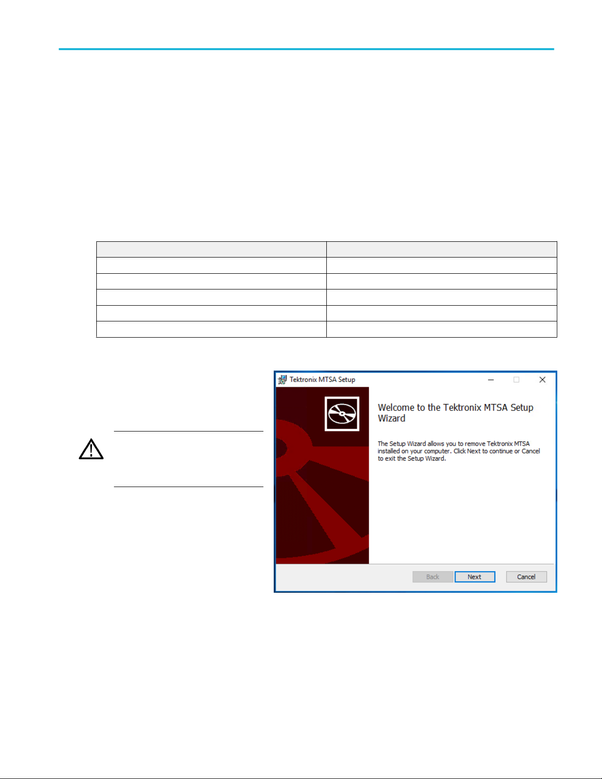
The installation program will start and
display a Welcome screen.
3. In the installation Welcome screen, select
Next.
MTSA-HW and MTSA-PC Quick Start User Manual 15

Installation
4. Read the End-User License Agreement.
Accept the agreement and select Next.
5. In the Choose Setup Type screen, select
Install on MTSA-PC to install the MTSA
software on your PC.
6. Select Next.
16 MTSA-HW and MTSA-PC Quick Start User Manual

Installation
7. In the Ready to Install screen, select
Install.
NOTE. A number of installation message
boxes display during the installation
process. Normally, no user intervention is
required.
If the installation program detects an
older version of the MTSA software, the
software is automatically uninstalled.
8. Allow the installation to proceed.
9. When the DESkey installer displays,
select Next to proceed with the DESkey
installation process. Depending on the
Windows security settings, you may see
a Windows Security message to install
device software. Select Install.
The DESkey installation is skipped if the
MTSA installation process detects that
the correct version of DESkey is already
installed.
10. When the WinPcap installer displays,
select Next.
Proceed with the WinPcap installation
process.
The WinPcap installation is skipped if the
MTSA installation process detects that
the correct version of WinPcap is already
installed.
MTSA-HW and MTSA-PC Quick Start User Manual 17

Installation
11. When installation completed screen
displays, select Finish.
A reboot is necessary before entering the
option key or using the applications.
18 MTSA-HW and MTSA-PC Quick Start User Manual

Installation
12. After the PC has restarted, install the
MTSA USB hardware key (dongle) in the
USB port of the local machine or confirm
that the hardware key has been plugged
in and detected by the remote dongle
server (Option FLT only).
13. After the PC detects the hardware key
dongle, open the MTSA Option Key
Wizard by selecting Tektronix MTSA >
OptionKey Wizard.
14. In the Tektronix Option Update dialog
box, enter the Option Key String supplied
with the installation documentation in the
Key String field.
15. Click Apply.
16. Inspect and verify the list of licensed
options.
NOTE. Operational access to features is
controlled by the licenses that are
available on the hardware key.
Applications and features can be
installed, but will not be available unless
the appropriate license has been
obtained. Notification of these is provided
when the product or additional licenses
are purchased.
The MTS4EA licensing is stored in the
USB dongle. The PQA software require
separate licensing.
17. Close the Option Key Wizard.
18. The licensed MTSA-PC standalone
applications can now be started from the
Windows Start menu or from the
shortcuts in the desktop folders (Real
Time Analyzers, Deferred Time
Analyzers, Generators, Player, or
Utilities). See Starting an application on
page 24.
MTSA-HW and MTSA-PC Quick Start User Manual 19

Installation
VLC media player installation
To be able to view video in the Transport Stream Compliance Analyzer (TSCA), the latest version of the VLC Media Player must
be downloaded from the VideoLAN Web site and installed.
1. Using an MTSA-HW instrument or PC
with access to the internet, navigate to
the VideoLan home page
(www.videolan.org).
2. Locate and download the Windows selfextracting VLC Media Player installer to
your PC hard disk. It is recommended
that you use the 64-bit version.
3. Locate the downloaded VLC Media
Player file on your instrument and run it.
4. Select your preferred language. The
Welcome / Setup screen appears.
5. Follow the setup procedure and allow the
VLC Media Player to be installed.
No further activity is required. The VLC Media Player will be used by the TSCA application as required.
20 MTSA-HW and MTSA-PC Quick Start User Manual
Operation
Product description
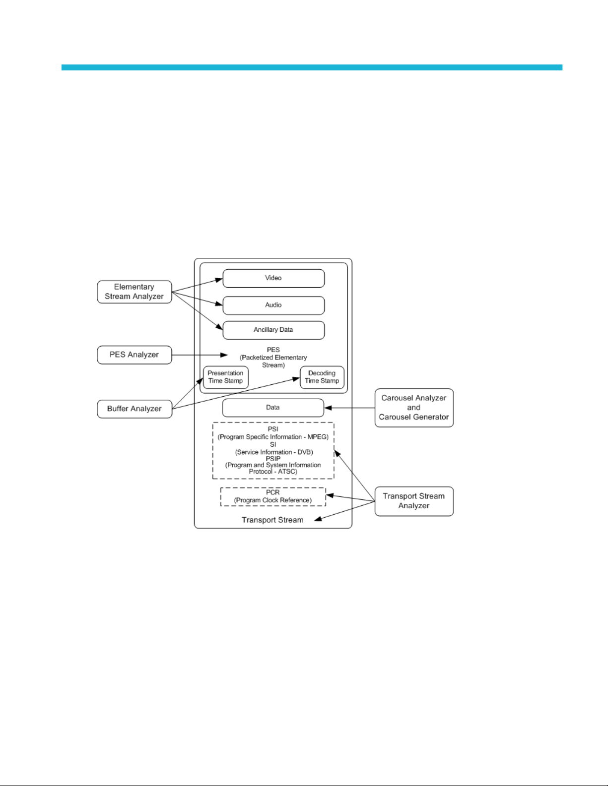
The MTSA-HW and MTSA-PC MPEG Test Systems provide a comprehensive and integrated suite of real-time and deferred
(offline) analysis tools. The tools include TS (transport stream) compliance, buffer, PES, MPEG2, and MPEG4 video and audio
elementary stream analyzers. Also included are an editor and a multiplexer to create stream content, and test and error-stressing
streams.
The applications in the MTSA analysis toolset are targeted at a specific aspect or layer of a transport stream. The following figure
illustrates this principle in simplified form.
The Procedures section tells you how to start the application, how to analyze a test stream, and what results are presented. The
procedures do not tell you how to interpret the results.
Standards compliance is ensured though built-in customizable scripting, which supports a broad range of ratified and evolving
DTV standards. New standards and proprietary tables can easily be implemented by loading Tektronix supplied updates, or
creating your own custom scripts.
MTSA-HW and MTSA-PC Quick Start User Manual 21

Operation
Software applications
This section provides an overview of the software applications that make up the MTSA MPEG Test Systems. Note that some
options might not be enabled. Detailed descriptions of all applications can be found in the MTSA application user manuals.
Application Icon
Analyzers
Transport Stream Compliance Analyzer (TSCA) –
Real-time and Deferred time transport stream
analysis with user-selectable MPEG-2, DVB, and
ATSC conformance tests. Shows transport structure,
The first RF/IP card installed in the MTSA-HW Test
System is accessed using the TS Compliance
Analyzer icon located in the Real Time Analyzers
folder on the desktop and in the Start menu.
header contents, hexadecimal packet contents, PCR
timing /transport rate graphs and error message logs.
Packetized Elementary Stream (PES) Analyzer – PES analysis with selectable test options. Shows PES
program structure, header contents, packet contents, PTS/DTS timing graphs and analysis reports.
Transport Stream – System Target Decoder (T-STD) Buffer Analyzer analyzes program streams modeling
their behavior in, and their conformance to, the MPEG-2 T-STD Buffer Model. Includes a trace facility.
1
Elementary Stream – Analyzer Elementary Stream analysis at video picture and audio level. This includes
vector graphs and macroblock picture quality.
Carousel Analyzer – Data analysis showing structure, bit rate, repetition rate, syntax and semantics of data
items.
Generators
Carousel Generator – Provides in-depth, off-line generation of MPEG-2, DVB transport streams containing a
range of data broadcast protocols.
ISDB-T Remux – Remultiplexes an existing 188- or 204-byte transport stream file into an ISDB-T/Tb (ARIB
STD-B31) compliant file (204 bytes per packet). The created file extension is .RMX and includes TMCC and
IIP sections.
1
If installed and licensed.
22 MTSA-HW and MTSA-PC Quick Start User Manual
Operation
Application Icon
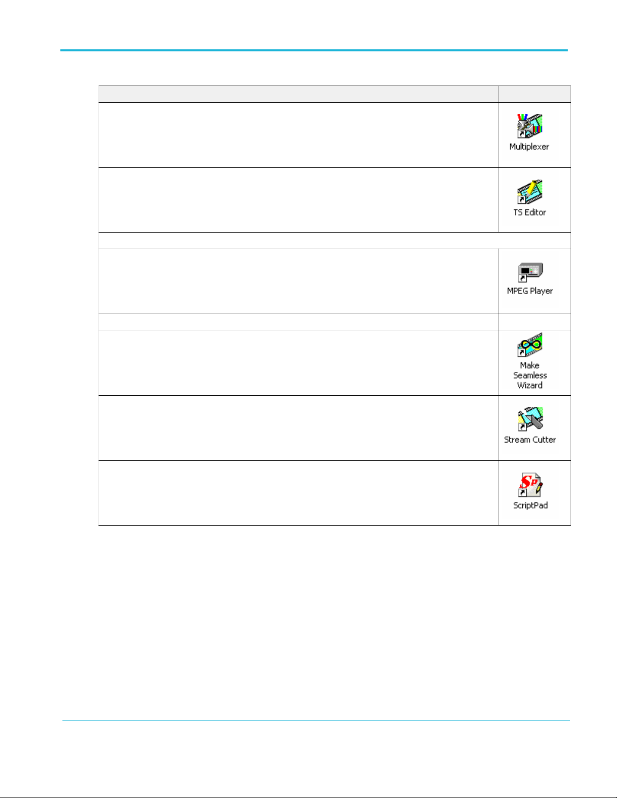
1
Multiplexer – Multiplexes table information and packetized elementary streams together to synthesize new
transport streams. A fine level of control is provided to allow nonconformances and test cases to be
specified for new transport streams.
TS Editor – Viewing and editing of transport stream packets, using a hexadecimal view of the packet
contents and semantic interpretation of the header. Provides facilities to remap PIDs, recalculate PCR
values and introduce PCR inaccuracies.
Players
MPEG Player – Plays MPEG-2 transport streams.
Utilities
Make Seamless Wizard – Guides the user through the process of creating an MPEG-2 transport stream file
for use by Stream Player in continuously looped operation.
Stream Cutter – Extracts sections of MPEG-2 transport stream files to new files.
Script Pad – Enables users to create and modify System Information (SI) scripts.
1
If installed and licensed.
MTSA-HW and MTSA-PC Quick Start User Manual 23
Operation
Starting an application
All applications are started from Start > All Programs > Tektronix MTSA menus or from the shortcuts in the desktop folders (Real
Time Analyzers, Deferred Time Analyzers, Generators, Player, or Utilities).
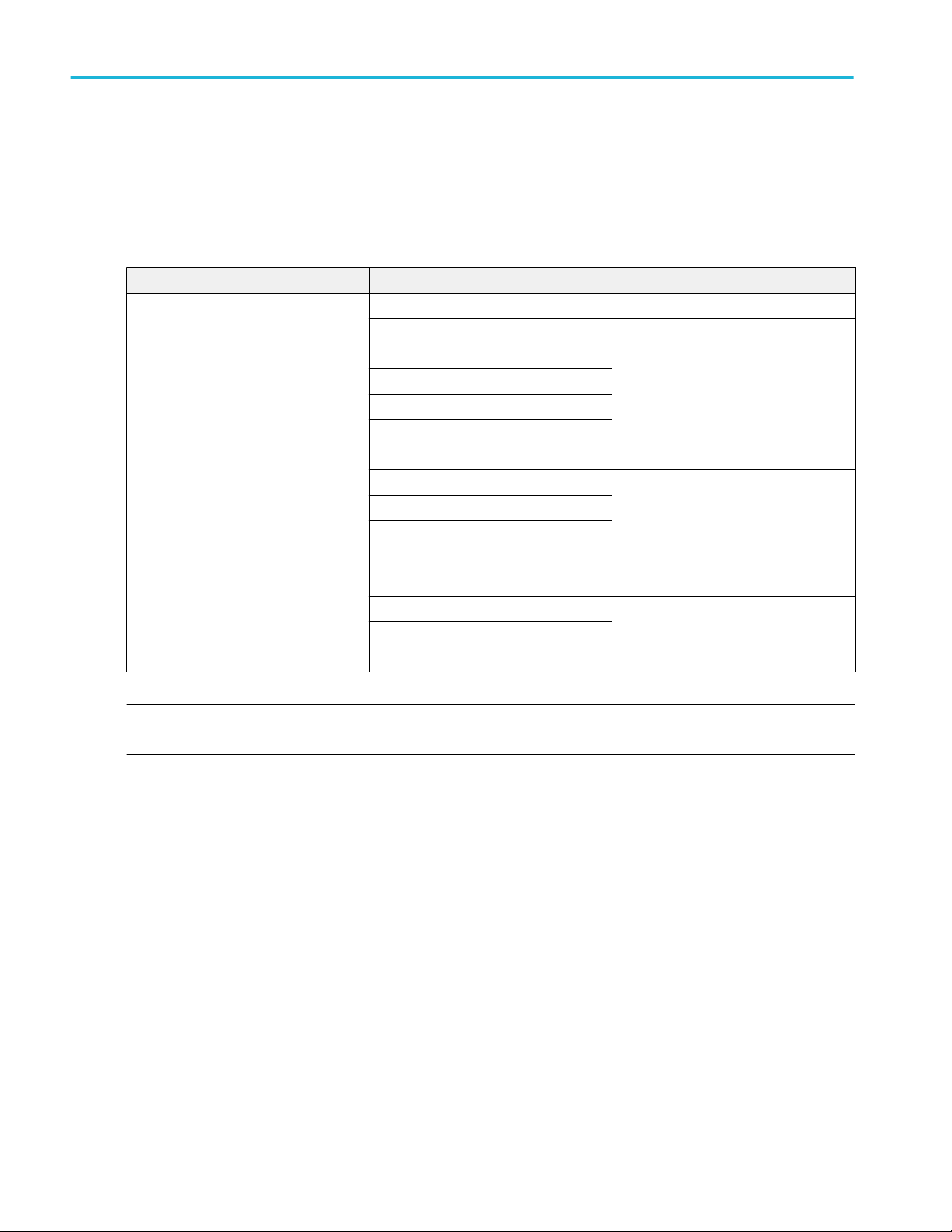
The MTSA application user manuals provide full descriptions of all applications. The following table shows the applications that
display in the Windows 10 Start menu.
Start menu Application Function
Tektronix MTSA > Option Key Wizard Product licensing
Buffer Analyzer Analyzers
Carousel Analyzer
ES Analyzer
PES Analyzer
TS Compliance Analyzer
TSCA with real time capabilities
Carousel Generator Generators
ISDB-T Remux
Multiplexer
TS Editor
MPEG Player Player
Make Seamless Wizard Utilities
ScriptPad
Stream Cutter
NOTE. Applications appear in alphabetical order in the Start menu. All applications are shown in the Start menu, but you can only
open those options that have been purchased and licensed.
Duplex operation
The MTSA-HW instrument can be operated in duplex mode (ASI or IP only). For example, while the Player is playing out a
stream, the Transport Stream Compliance Analyzer (TSCA) can be analyzing a separate stream or, if the output is looped back
to the input, the output of the Player can be monitored by the TSCA.
24 MTSA-HW and MTSA-PC Quick Start User Manual

Operation
Setting up loopback
With loopback in operation you can:
■
Use the MPEG Player to play out a stream
■
Loop the instrument output back to the input (For example, with the ASI card, loop ASI-4 back to ASI-3. With the 10G card,
loop the output back to the input using an LC multimode jumper cable.)
■
Monitor/analyze the incoming stream using the TSCA
Before starting:
■
Identify the stream to be played out (in this example, the sym1.mpg test stream is used).
■
Choose the output/input interface (ASI) and make the necessary connections (loop between the connectors).
In the following example, the stream is looped back using the ASI interface and the stream is looped in the player (to play
continuously).
MTSA-HW setup.
1. Connect a cable from the ASI-4 connector to the ASI-3 connector.
MPEG player setup.
1. Open the MPEG Player: Tektronix MTSA > MPEG Player.
2. Open a stream: File>Open...> Sym1.mpg.
NOTE. The Sym1.mpg file is provided for use to help understand the MTSA applications. The file is available in several
locations such as the hard drive of the MTSA-HW (C:\Streams\Tclips\MTS400 TestStreams) or the Tclips download from
www.tek.com.
3. Make the following settings in the Play menu:
■
Interface: ASI
■
Packet size: 188
■
Update: On
■
Loop: On
■
Other: Standard: DVB
4. Make the following settings in the ASI menu:
■
ASI Out: ASI-4
TSCA setup.
1. Open the TSCA: Tektronix MTSA > TS Compliance Analyzer.
2. In the start-up dialog box (Open Transport Stream...), select Change... in Stream Interpretation and select the DVB base
standard with no extensions. Close the Stream Interpretation dialog box.
3. Select Real-time Analysis and select ASI-3 from the Interfaces drop-down list.
4. Select OK.
MTSA-HW and MTSA-PC Quick Start User Manual 25

Operation
Start the playout and analysis.
1. Return to the MPEG Player window and play the stream by selecting: Play>Start/Stop or use the toolbar button.
2. In the Player window, note that the status bar is now displayed and that playout has started.
3. Return to the TSCA window and note that analysis has started.
The MPEG Player is now playing out the sym1.mpg transport stream and, through the ASI input and output on the instrument
connector panel, the TSCA is monitoring and analyzing the stream.
For detailed descriptions of the MPEG Player and the TSCA, refer to the MTSA-HW and MTSA-PC Generator Applications User
Manual.
Interface card status LEDs
The rear panel on the optional ASI and DVB-S2 (Option DS2) interface cards have LEDs to indicate the status of the input and
output signals. The following tables list the possible status conditions.
Table 4: ASI and DVB-S2 outputs
LED pattern Description
Short orange flashes No output is generated
Long orange flashes Null-packet stuffing only (no real data)
Solid orange Generating live output
Table 5: ASI and DVB-S2 inputs
LED pattern Description
Short green flashes No carrier/signal detected
Long green flashes Carrier detected but no data
Solid green Valid signal detected
Solid red Wrong signal connected
Five short red flashes quickly after each other Code violations
26 MTSA-HW and MTSA-PC Quick Start User Manual

Operation
Floating license operation
When your MTSA-HW or MTSA-PC system has Option FLT installed, there may be times when you are not able to run a MTSA
application because all of the floating licenses are in use. Perform the following steps if you need to force-quit a remote session
of the MTSA software in order to free up a license:
1. Login as Administrator on the floating license server machine.
2. Open the Control Panel (Settings > Control Panel) and select the DESkey icon. This will show the DESkey Configuration
dialog (the version numbers shown near the bottom may vary).
3. Select the Networking tab and click the Monitor button. This will show the DK2 Network Server Remote Monitor dialog.
4. In the DK2 Network Server Remote Monitor dialog, click the Admin button.
MTSA-HW and MTSA-PC Quick Start User Manual 27
Operation
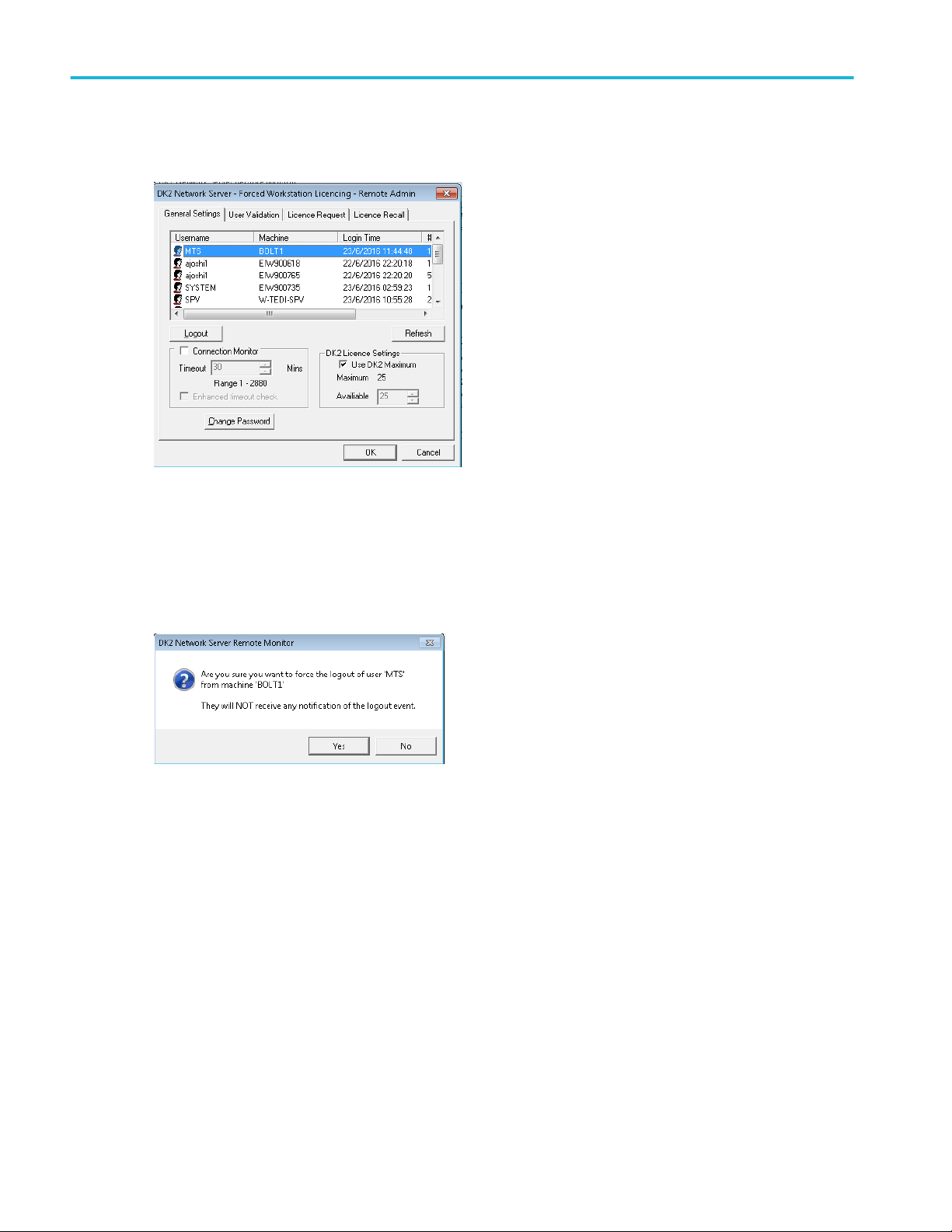
5. Enter deskey as the password in the Password Required box, and then click OK. This will show the DK2 Network Server Forced Workstation Licensing - Remote Admin dialog shown below.
6. In the DK2 Network Server - Forced Workstation Licensing - Remote Admin dialog, click the General Settings tab, and then
select client machine that you would like to force out of the MTSA software license.
7. After you select the desired client machine, click the Logout button.
8. In the confirmation window, verify you have selected the correct client machine, and then click Yes to proceed with the
force-quit operation.
9. After the force-quit operation is complete, the selected MTSA floating license is released to the pool of available licenses.
Repeat this procedure as necessary to free up the desired number of licenses.
10. After you are done freeing up licenses, click OK to close the DK2 Network Server - Forced Workstation Licensing - Remote
Admin dialog.
28 MTSA-HW and MTSA-PC Quick Start User Manual
Procedures
Using the Multiplexer
The following application example describes using the Multiplexer to create a new transport stream and add elementary streams
to the transport stream.
The new transport stream created with this procedure (named TestMux.mpg) is used to complete some of the additional
procedures in this manual.
Create a new stream using the Multiplexer
In this section of the application example, you will create a new transport stream using the Multiplexer application. You will
introduce one error so that you will be able to observe it in a later section of the application example.
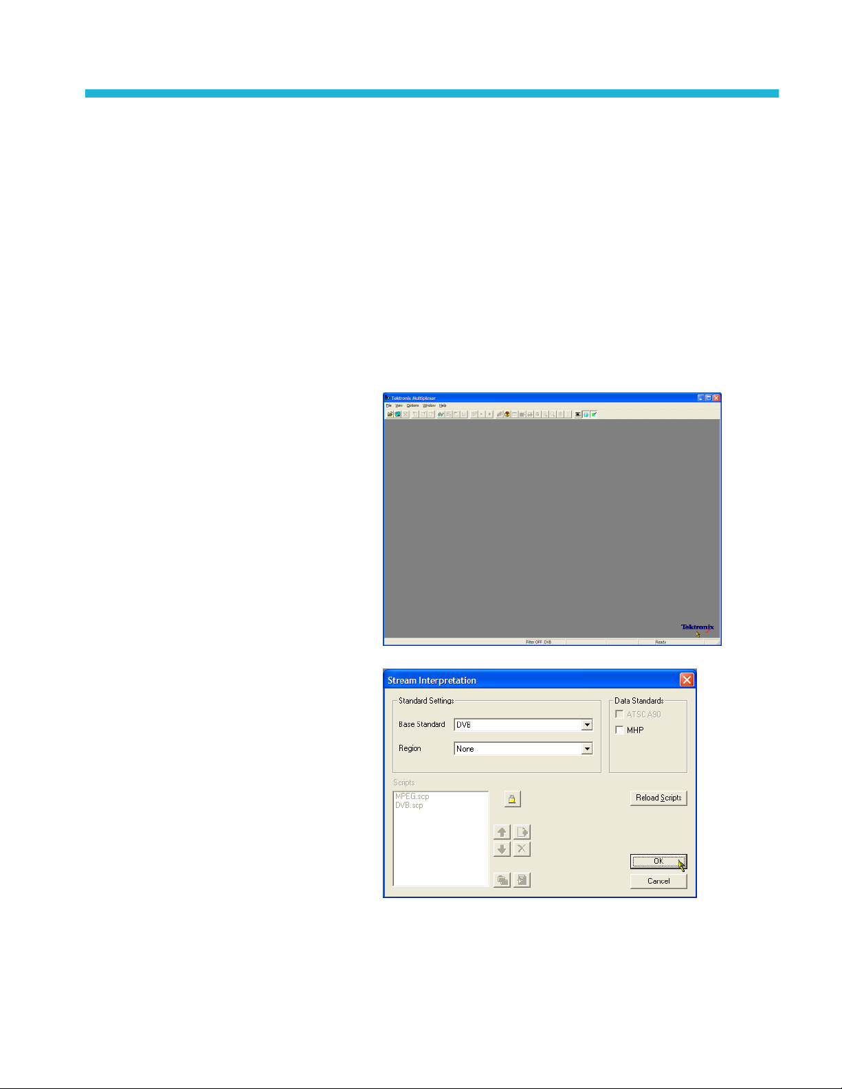
1. Open the Multiplexer application.
Tektronix MTSA > Multiplexer.
2. Select View > Interpretation.
3. In the Stream Interpretation dialog box,
ensure that the selected Base Standard
is DVB and that the Region is None.
4. Select OK to close the Stream
Interpretation dialog box.
MTSA-HW and MTSA-PC Quick Start User Manual 29
Procedures
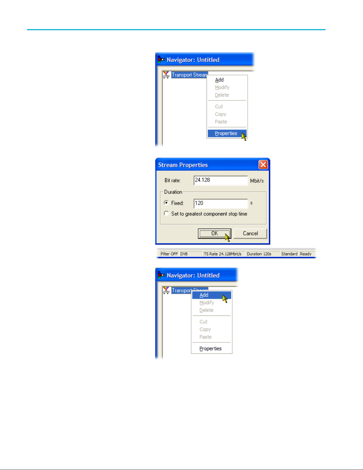
5. Select File > New.
6. In the Navigator window, highlight the
Transport Stream node and select
Properties from the context menu.
7. In the Stream Properties dialog box, enter
a bit rate of 24.128 Mbit/s and a fixed
duration of two minutes (120 seconds).
Select OK.
Note that the two values are displayed in
the status bar.
8. In the Navigator window, highlight the
Transport Stream node and select Add
from the context menu.
30 MTSA-HW and MTSA-PC Quick Start User Manual
Procedures
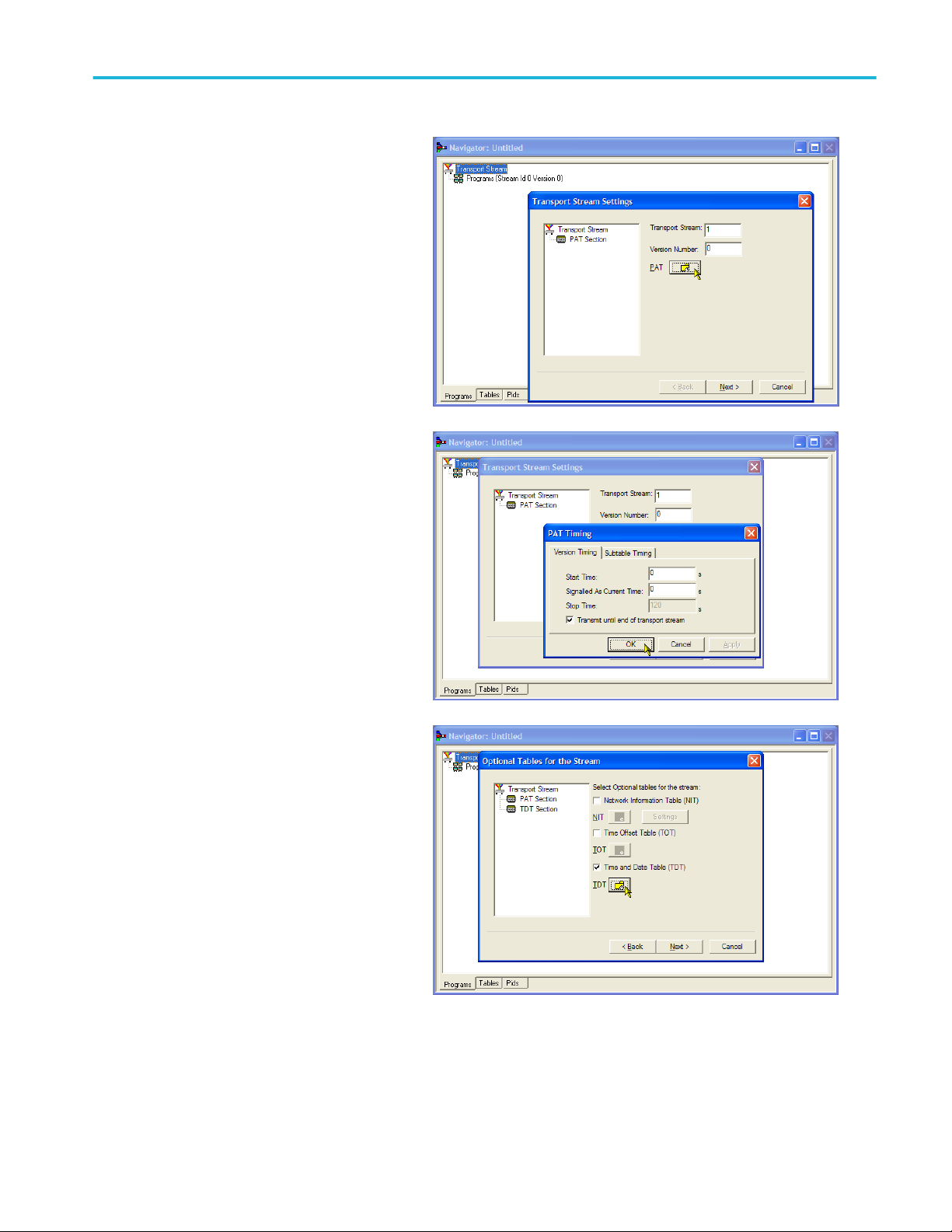
9. In the Transport Stream Settings dialog
box, enter 1 as the Transport Stream
identity.
10. Select the PAT (Program Allocation
Table) folder icon button to open the PAT
Timing dialog box.
In the Version Timing tab window, note that
the PAT timing Start time (0 s) and Stop time
(120 s) mean that the PAT will be transmitted
for the stream duration.
11. Select OK to close the PAT Timing dialog
box.
12. In the Transport Stream Settings dialog
box, select Next.
13. In the Optional Tables for the Stream
dialog box, select the TDT (Time and
Date Table) check box and select the
TDT folder icon button.
MTSA-HW and MTSA-PC Quick Start User Manual 31

Procedures
In the TDT Timing dialog box, confirm that the
Start Time is zero and the Stop Time is the
same as the duration previously set.
Note that the duration may have been
adjusted by an insignificant amount. In this
example, the set duration of 120 s is now
displayed as 119.999976127.
14. Enter a Cycle Time of 1000 ms.
15. Select OK to close the TDT Timing dialog
box.
16. In the Optional Tables for the Stream
dialog box, select the NIT (Network
Information Table) check box and select
the NIT Settings button.
17. In the Set up the NIT dialog box, enter
the Network Id 1234 and the Network
Name Tek_test.
18. Set the Original Network identity to 2 and
select Terrestrial from the Delivery
System drop-down list.
19. Select the Delivery System Settings
button.
32 MTSA-HW and MTSA-PC Quick Start User Manual

Procedures
20. In the Terrestrial Settings dialog box,
enter 0x123456 in the Centre Frequency
field.
21. Select 2 (64-QAM) from the Constellation
drop-down list.
22. Select 4 (non-hierarchical, in-depth
interleaver) from the Hierarchy
Information drop-down list.
23. Select 1 (8k mode) from the
Transmission Mode drop-down list.
24. Select OK to close the Terrestrial
Settings dialog box.
25. Select OK to close the Set up the NIT
dialog box.
26. In the Optional Tables for the Stream
dialog box, select Next to display the
Transport Wizard Complete dialog box.
The transport stream set up is complete.
Now you need to add some content in the
form of video and audio elementary
streams.
Do not close the Transport Wizard
Complete screen.
MTSA-HW and MTSA-PC Quick Start User Manual 33

Procedures
Elementary stream acquisition. For this example, you need to add a video and an audio elementary stream to the transport
stream that you have created. You can extract suitable streams from one of the sample transport streams supplied with the
MTSA installation. The stream used in this example is Sym1.mpg. This file is available on the hard drive of the MTSA-HW and
the Tclips MPEG Test Streams DVD.
1. Open a second instance of the
multiplexer. Tektronix MTSA >
Multiplexer.
2. Select File > Open.
3. In the Set MPEG File to Edit dialog box,
locate and open sym1.mpg.
4. Expand the program 1 node and the
dependent Elementary Streams node.
5. Highlight the PID 110 node. This PID is
carrying an MPEG-2 video elementary
stream.
6. Select Export Elementary Stream in the
context menu.
7. In the Save As dialog box, enter a file
name (Sym1pid110.es) and save the file
to a suitable location.
8. Repeat the action for PID120. Name the
file Sym1pid120.es.
9. Select File > Exit to close this instance of
the Multiplexer.
This completes the extraction of the video
and audio elementary streams. You can
continue with the multiplexing task.
34 MTSA-HW and MTSA-PC Quick Start User Manual

Procedures
Add elementary streams. Now you can return to the original multiplexer instance and add the elementary streams that you have
just created.
1. Ensure that Add a Program Wizard is
checked and select Next.
2. In the Add a Program dialog box, enter
1 as the program number.
3. Select the PMT folder icon.
4. In the PMT Timing dialog box, select the
Subtable Timing tab.
The subtable timing cycle time is the
period over which a table is repeated in
the stream. The maximum cycle time for
the PMT in the DVB standard is 500 ms.
5. For this example stream, set the cycle
time to 525 ms.
6. Select OK to close the PMT Timing
dialog box.
7. In the Add a Program dialog box, select
Next.
MTSA-HW and MTSA-PC Quick Start User Manual 35

Procedures
8. In the Add Service Description dialog
box, select the Add Service Description
check box.
9. Enter a Service Provider Name, for
example, Tek Broadcasting.
10. Enter a Service Name, for example,
Tek1.
11. Enter a Service Type, for example,
1 (0x1) (digital television service).
12. Select Next.
13. In the Add the Program Content dialog
box, select Add to add a video
elementary stream.
14. In the Add Program Stream dialog box,
select 2 (0x02) (MPEG-2 Video) from the
Stream Type drop-down list.
15. Ensure that the Source tab is selected.
16. Enter a File Name, or use Browse to
locate the video elementary stream
previously set up (Sym1pid110.es).
17. Select MPEG-2 video from the File type
drop-down list. Note that the file bit rate
has been entered automatically.
36 MTSA-HW and MTSA-PC Quick Start User Manual
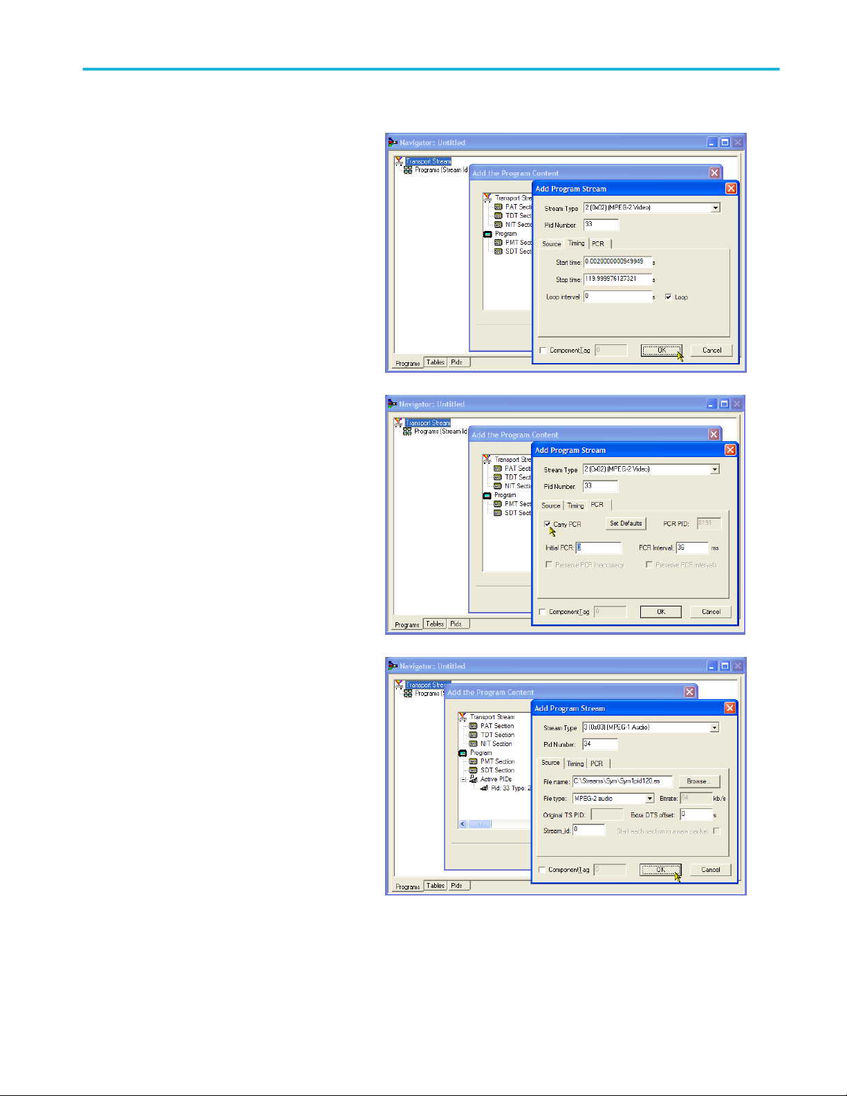
Procedures
Select the Timing tab. Note that the
elementary stream is going to run for the
length of the stream previously set, that is,
120 s.
18. Select the PCR tab. Ensure that the
Carry PCR check box is selected.
19. Select OK to close the Add Program
Stream dialog box.
20. In the Add the Program Content dialog
box, select Add again to add an audio
elementary stream.
21. Select 3 (0x03) (MPEG-1 Audio) from
the Stream Type drop-down list.
22. In the Add Program Stream dialog box,
ensure that the Source tab is selected.
23. Enter a File Name, or use the Browse
button to locate the audio elementary
stream previously set up
(Sym1pid120.es).
24. Select MPEG-2 audio from the File type
drop-down list. Note that the file bit rate
has been entered automatically.
MTSA-HW and MTSA-PC Quick Start User Manual 37

Procedures
25. Select the Timing tab. Note that the
elementary stream is going to run for the
length of the stream previously set, that
is, 120 s.
26. Select the PCR tab. Ensure that the
Carry PCR check box is cleared.
27. Enter 33 in the PCR PID field. This is the
PID that will carry the PCR information –
also the video es, Carry PCR.
28. Select OK to close the Add Program
Stream dialog box.
29. Select Next.
30. In the Event Information dialog box,
select the Event Information Tables (EIT)
check box.
31. Ensure that the Present check box is
selected.
32. Select Present Settings.
38 MTSA-HW and MTSA-PC Quick Start User Manual
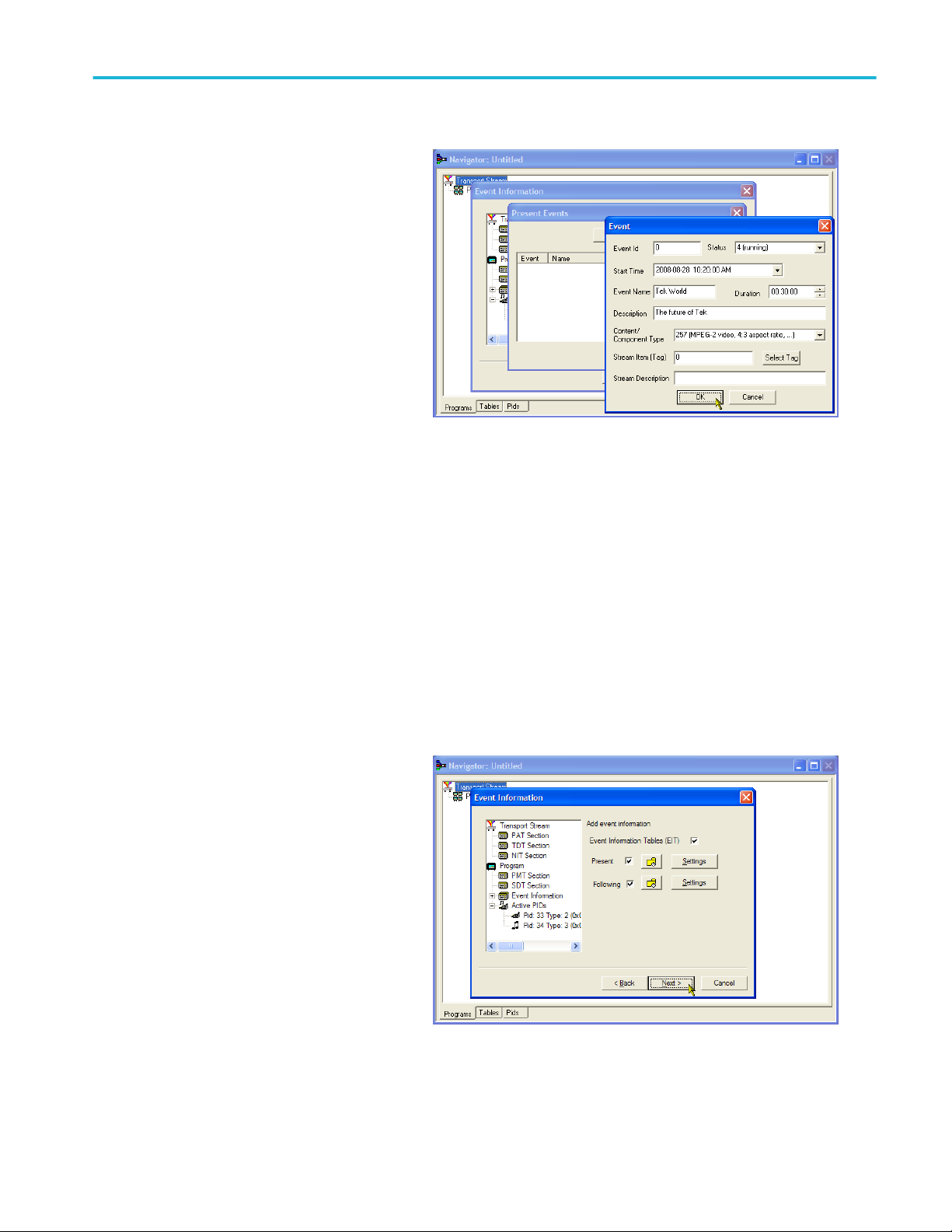
Procedures
33. In the Present Events dialog box, select
Add to set up the present event
information, that is, the time of this
broadcast. In the Event dialog box, select
4 (running) from the Status drop-down
list.
34. Set the Start Time to
2008-08-28 10:20:00 AM.
You can change the time and date by
highlighting the individual field and
entering the required value.
35. Enter an Event Name, for example, Tek
World.
36. Enter a Description, for example, The
future of Tek.
37. Enter a Duration, for example, 30m
(00:30:00).
38. Select 257 (MPEG-2 video, 4:3 aspect
ratio, ...) from the Content/Component
Type drop-down list.
39. Select OK to close the Event dialog box.
40. Select OK to close the Present Events
dialog box.
41. Ensure that the Following check box is
selected.
42. Select Following Settings.
43. Select Add to set up the following event
information, that is, the event following
the present event.
44. In the Event dialog box, enter 1 in the
Event Id field.
45. Select 1 (not running) from the Status
drop-down list.
46. Set the Start Time to
2008-08-28 10:50:00 AM.
47. Enter an Event Name, for example, Tek
News.
MTSA-HW and MTSA-PC Quick Start User Manual 39

Procedures
48. Enter a Description of the event, for
example, All the latest news from Tek.
49. Enter a Duration, for example, 30 m
(01:00:00).
50. Select 257 (MPEG-2 video, 4:3 aspect
ratio, ...) from the Content/Component
Type drop-down list.
51. Select OK to close the Event dialog box.
52. Select OK to close the Following Events
dialog box.
53. Select Next in the Event Information
dialog screen.
54. In the Program Complete dialog box,
select Finish.
You have finished creating the structure and
content of the proposed transport stream. You
can now make a couple of checks to ensure
that the stream will compile successfully.
55. Select View > Available Bitrate.
In the Available Bitrate graph, note that
the bit rate remains within the required
bitrate, that is, 124.128 Mbps.
You can examine the bit rate at any point
on the graph, by clicking a point and
reading the values from the adjacent
table.
56. Close the Available Bitrate graph.
40 MTSA-HW and MTSA-PC Quick Start User Manual

Procedures
57. Select Multiplex > Start to start the
multiplex.
58. In the Set TS Output File... dialog box,
enter the name TestMux.mpg for the new
multiplexed transport stream. (This new
transport stream is used in other
procedures.)
Watch the right side of the Status bar for
the multiplexing progress; the progress
bar may be hidden if the window is too
small horizontally.
The elementary streams and structural
information have now been multiplexed
together to form the transport stream,
TestMux.mpg.
59. It is a good idea to save the structure of
the multiplex, so that it can be recalled
and more information added to it as
required.
60. Select File > Export....
61. In the Export File dialog box, enter a
name for the multiplex structure file, for
example, TestMux.muxml and select a
location to save the file. Note the muxml
extension.
62. Using File > Import, the multiplex
structure file can be reopened at any time
to add elementary streams or structural
information.
MTSA-HW and MTSA-PC Quick Start User Manual 41
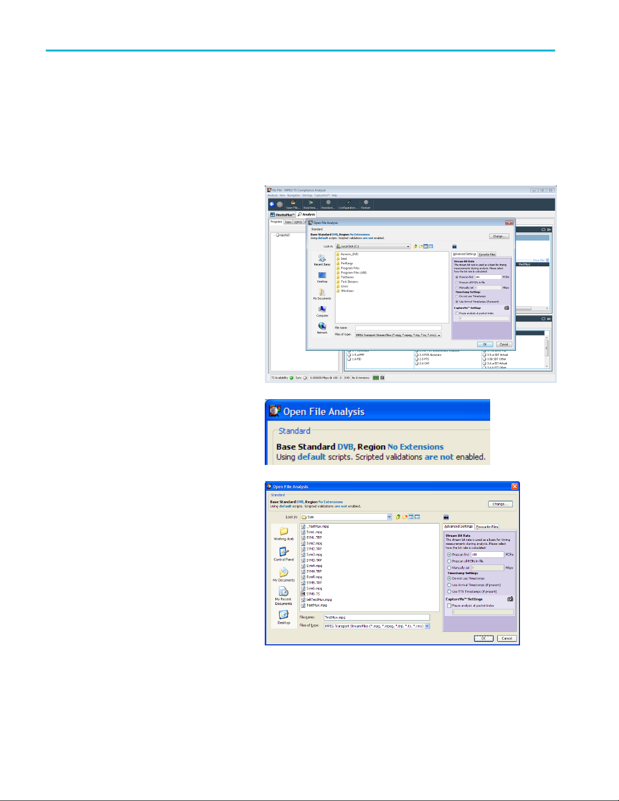
Procedures
Using the Transport Stream Compliance Analyzer
The following procedure examines a transport stream off-line using the File Analysis mode of the Transport Stream Compliance
Analyzer (TSCA) application. The procedure uses the transport stream (TestMux.mpg) created in the Using the Multiplexer
procedure.
Use the Real-time Analysis to analyze live data. Multiple input monitoring on page 61
1. Open Transport Stream Compliance
Analyzer. Tektronix MTSA > TS
Compliance Analyzer.
The Open File Analysis dialog box
displays automatically. If not, select File
Analysis in the TSCA Analysis toolbar.
In the Open File Analysis dialog box, ensure
that the Base Standard is DVB and the Region
is No Extensions.
2. Locate and select the example stream,
TestMux.mpg.
Ensure that in the Advanced Settings
pane, the Stream Bit Rate and the
Timestamp Settings are as shown.
42 MTSA-HW and MTSA-PC Quick Start User Manual
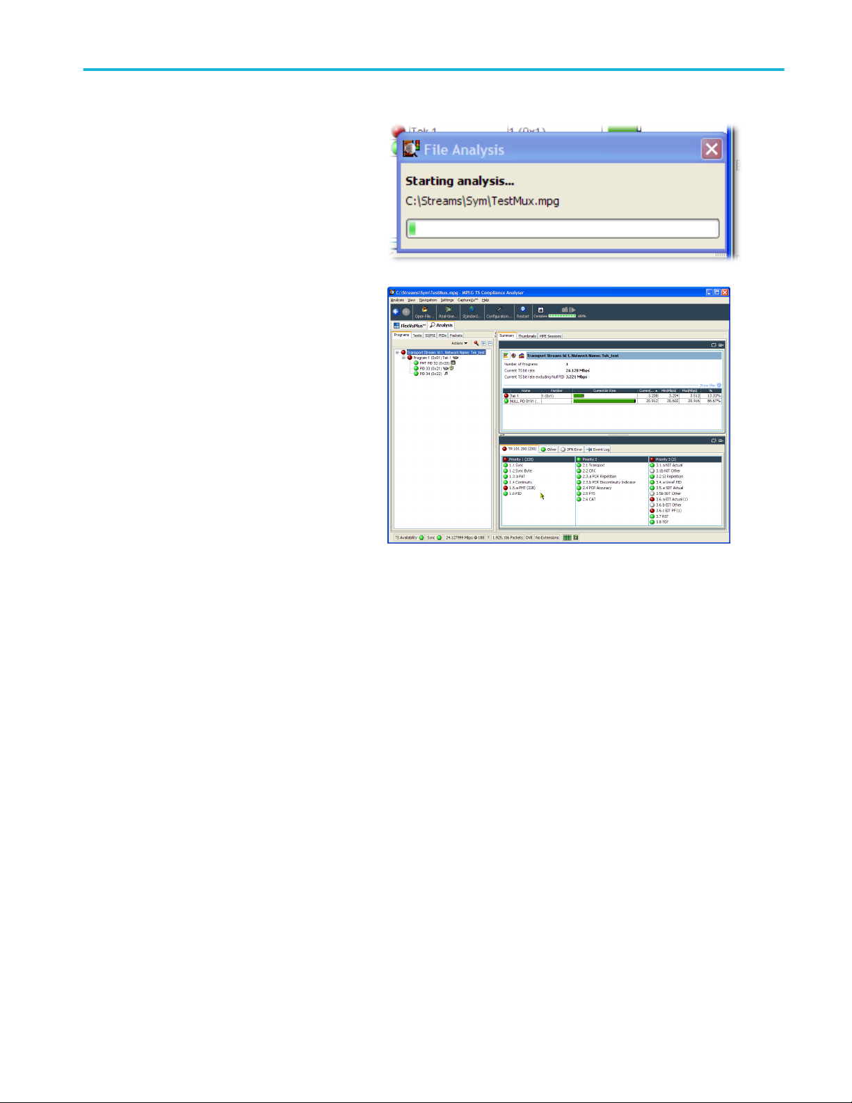
Procedures
3. The analysis will take a moment to
complete.
4. Select the Analysis tab to display the
navigation and related views.
5. Select the Programs tab and expand the
nodes in the navigation view by clicking
the plus symbols.
In the detail views, ensure that the
Summary view and the Tests view are
displayed.
The Transport Stream node and the
Program node are both red. This shows
that an error has occurred in the stream
and is still active.
6. Highlight the Transport Stream node. In
the Tests Summary detail view, TR
101 290 tab, note that test 1.5.a PMT is
indicating an error, that is, the associated
LED is red.
MTSA-HW and MTSA-PC Quick Start User Manual 43

Procedures
7. Highlight test 1.5.a PMT and select View
this test in the Tests tree from the
context menu.
The Tests tab views are displayed. The
navigation view is expanded to show the failed
test. The detail view shows any PIDs
associated with the highlighted test (none in
this example) and the event log filtered to
show only events for the highlighted test.
Examine the log entries for error information.
Note that the error reports refer to a duration
of 525 ms. This is the PMT section repetition
rate; 525 ms was the value set in the example
stream created earlier.
44 MTSA-HW and MTSA-PC Quick Start User Manual

Procedures
8. In the navigation view, highlight the
1.5 PMT (Timer) test and select Edit
Parameters from the context menu.
9. In the Edit Parameters dialog box, note
that for this stream the PMT section
maximum repetition interval is set to
500 ms. Since the repetition rate found in
this stream exceeds this value (525 ms),
it is being reported as an error. However,
by examining the maximum and minimum
repetition rates shown in the Edit
Parameters dialog box (hover the mouse
pointer over the value field and refer to
the tool tip), you can see that the rate of
525 ms is within the range recommended
by the DVB standard, 40 ms to
25000 ms.
MTSA-HW and MTSA-PC Quick Start User Manual 45

Procedures
Using the PES Analyzer
The elementary streams (including video, audio, and ancillary data) are combined into a packetized elementary stream (PES).
The header associated with each PES packet in a transport stream is of particular interest, as it contains the decode and
presentation timestamps (DTS and PTS) for the contained elementary streams. Errors in these timestamps may cause resets or
picture freeze problems at the receiver in extreme cases.
1. Open the PES Analyzer. Tektronix
MTSA > PES Analyzer.
2. Select File > Open. Locate and open a
transport stream. For example, the
TestMux.mpg file created in the Using the
Multiplexer procedure.
The analysis progress is displayed in the
status bar and the Event Log. The
Program Structure view is displayed
when analysis is complete. In this
example you can see that the stream
carries a single program, which contains
one video and one audio elementary
stream on PIDs 33 and 34 respectively.
3. Select the video stream in the Program
Structure view; the magnifying glass icon
will indicate that it has been selected.
4. Open each view option in the View menu,
that is, Event Log, Hex, Interpretation,
and PTS/DTS Timing. Each action opens
a new view in the PES Analyzer window.
It may be useful to tile the views in the
window using the Window > Tile option.
You can use the slider bar, above the
status bar, to navigate to any packet in
the PES stream. Packets are numbered
within a PID, according to their position in
the file. The slider bar displays the packet
number and the PID for the current
packet.
46 MTSA-HW and MTSA-PC Quick Start User Manual

Procedures
Packet Hex View:
In this view, you can examine every byte in the
PES.
■
The four digit numbers in the left column
are the addresses of the first byte in the
row.
■
The bytes displayed in magenta
represent the PES packet header. You
can view this as a graphical
representation in the Packet
Interpretation view.
Packet Interpretation View:
This window interprets and displays a
graphical representation of the header of the
currently selected packet. The size of the
header will vary depending on the packet
content.
MTSA-HW and MTSA-PC Quick Start User Manual 47

Procedures
PTS/DTS View:
This view shows a timing analysis of the
selected stream. The X-axis shows the
duration of the stream in seconds. The Y-axis
shows the differences between the expected
and actual DTS values. Vertical blue lines
show the difference between the PTS and
DTS for each access unit. Additional access
unit information is shown in the side panel.
A compliant stream will show each DTS on the
0 ms Y-axis; streams with errors usually show
a stepped graphical effect.
Select the toolbar magnifying glass and click
on the view to zoom in and out of the graph.
The slider at the bottom of this window
indicates where the displayed packets are in
relation to the rest of the file.
48 MTSA-HW and MTSA-PC Quick Start User Manual

Procedures
Using the T-STD Buffer Analyzer
The T-STD Buffer Analyzer application models the behavior of the buffers in the hypothetical Transport Stream System Target
Decoder, as specified in ISO/IEC 13818-1. It can process video, audio, and system control streams. The results of the analysis
are displayed as graphs of the buffer capacity over time and a log of exceptions and noteworthy events. The consequences of
non-conformance to the buffer model can include freeze frames and receiver resets.
1. Open the T-STD Buffer Analyzer.
Tektronix MTSA > Buffer Analyzer.
2. Review the configuration settings. View >
Settings.
In the System tab of the Settings dialog
box, select MPEG2 Packet
Interpretation and select Pre-Scan
Packets All Packets.
MTSA-HW and MTSA-PC Quick Start User Manual 49

Procedures
3. In the Video tab, select Buffer Sizes,
Automatic and Data Transfer,
Automatic.
4. In the Audio tab, select Buffer Size,
Automatic.
5. Close the Settings dialog box.
50 MTSA-HW and MTSA-PC Quick Start User Manual

Procedures
6. Select a file for analysis. File > New.
7. Locate and open an MPEG file. For
example, the TestMux.mpg file created in
the Using the Multiplexer procedure.
Another file selection dialog box is
opened immediately. This is for you to
name and open a buffer model results
(BMR) file, which will hold the results of
subsequent analysis.
Accept the default name and open the
file.
The program performs initial analysis to
form a Stream List and calculate the
mean transport rate. The stream list
displays all of the programs and
elementary streams in the file. All
streams in the list are marked as
Unprocessed, because no analysis has
been performed on them in this session.
8. Select Process Streams from the
transport stream context menu to start
processing the stream.
Analysis progress is displayed in the
status bar.
MTSA-HW and MTSA-PC Quick Start User Manual 51

Procedures
9. Highlight PID 33 and select All Buffers
from the context menu.
The following windows will be displayed
for a video elementary stream: PID Event
Log, Video Transport Buffer, Video
Multiplex Buffer, and Video Elementary
Buffer. (The Stream List window has
been minimized.)
10. Tile the resulting windows: Window >
Tile.
PID Event Log:
You can open two event logs: a global
event log (View > Global Event Log)
that displays high level events occurring
in the initial analysis process and a PID
event log (View > PID Event Log) that
displays events for each processed PID.
In the following buffer graph views:
■
Use the toolbar magnifying glass icons to
zoom in and out of the selected graph.
Zoom value can be reset using the Reset
Zoom toolbar button.
■
All open graphs can be viewed and
manipulated separately. Use the Options
> Synchronize Views to synchronize all
views with the currently selected view.
■
Red y-axis lines indicate the 0% and
100% limits.
Video Multiplex / Main Buffer:
In this view, for video streams, you can see
the results of modeling a multiplex buffer. For
audio and system control streams, you can
see the results for the main buffer. The title bar
shows the stream type.
Video Transport Buffer:
This view shows results of modeling the
transport buffer for video, audio, or system
control streams.
Video Elementary Buffer:
This view shows only applicable video
elementary streams.
52 MTSA-HW and MTSA-PC Quick Start User Manual

Procedures
11. Select View > Trace to display the trace
log.
The trace log can help you analyze the
message logs produced by the Buffer
Analyzer. These logs may be useful for
in-depth analysis of the internal
processing, particularly for the video
stream type. The trace view has filtering
capabilities that allow you to focus on
message types of particular interest.
MTSA-HW and MTSA-PC Quick Start User Manual 53

Procedures
Using the ES Analyzer
The ES (Elementary Stream) Analyzer application checks for compliance of CODECs to MPEG-2 and H.263 standards. Audio
decode and waveform display of MPEG-2 audio (ISO/IEC 13818 parts 3 and 7), AC-3 and MPEG-4 AAC are also supported.
ES Analyzer is a complex application which you can use to analyze many aspects of video and audio streams. For this reason,
the following procedure shows you how to access some of the analysis screens; detailed explanation of their content and
meaning can be found in the MTSA-HW and MTSA-PC Analyzer Application User Manual.
1. Open the ES Analyzer. Tektronix MTSA
> ES Analyzer.
2. Select a file for analysis. File > Open.
Locate and open an MPEG file. For
example, the TestMux.mpg file created in
the Using the Multiplexer procedure.
3. Click on each successive node in the
navigation window until the GOP (Group
of Pictures) is highlighted in the Program
1 / PES (PID 33), MPEG 2 Video branch.
54 MTSA-HW and MTSA-PC Quick Start User Manual

Procedures
4. Select the Picture Player tab. Note that
the Picture Player remote control is
displayed.
5. Click the Show Information button to
expand the control bar. The extra
information shows the position in the file
of the displayed picture; more information
is shown in the status bar.
6. Start playing the stream by clicking the
play button on the control bar.
If you stop the playout, you can select the
other GOP tabs (GOP and Picture, Slice
and MB), and examine the characteristics
of that frame.
7. For example, select the Picture Display
on the Slice and MB tab. The picture will
correspond to the picture in the Picture
Player.
8. Click Show MV (motion vectors) on the
right of the picture display. For B and P
frames, the motion vectors will be
displayed as colored arrows overlaying
the picture.
MTSA-HW and MTSA-PC Quick Start User Manual 55

Procedures
Additionally, you can see the characteristics of
any of the macroblocks that make up the
picture by hovering the mouse over a picture
macroblock.
9. Use the Previous Frame and Next Frame
buttons to move backward and forwards
in the stream and compare the motion
vectors.
You can examine the characteristics of the
audio stream in a similar manner.
10. Click on each successive node in the
navigation window until the GOP (Group
of Pictures) is highlighted in the Program
1/PES (PID 34), MPEG 1 Audio branch.
Use the audio control bar to review the
audio track. You will need to use
headphones to hear the output.
56 MTSA-HW and MTSA-PC Quick Start User Manual

Procedures
TSCA FlexVuPlus display
In the Transport Stream Compliance Analyzer (TSCA), you can use the FlexVuPlus™ display to select up to four views from the
analysis detail views to be displayed together to facilitate basic transport stream monitoring or more detailed diagnostic
monitoring.
For this exercise, close each of the currently
displayed FlexVuPlus panels by clicking the X
in the top right corner of each panel.
This is not necessary, but it may help you
visualize the following procedure more easily
as each panel is populated. Note that each of
the four FlexVuPlus panels are numbered.
Set up panel 1
1. Select the Analysis tab and then the
Tests tab.
In the top right corner of all detail views is
a FlexVuPlus panel select button. You
can use this button to display a replica of
the detail view in the selected FlexVuPlus
panel.
2. In the Test Summary view, use the
FlexVuPlus panel select button to
replicate the view in panel 1.
MTSA-HW and MTSA-PC Quick Start User Manual 57
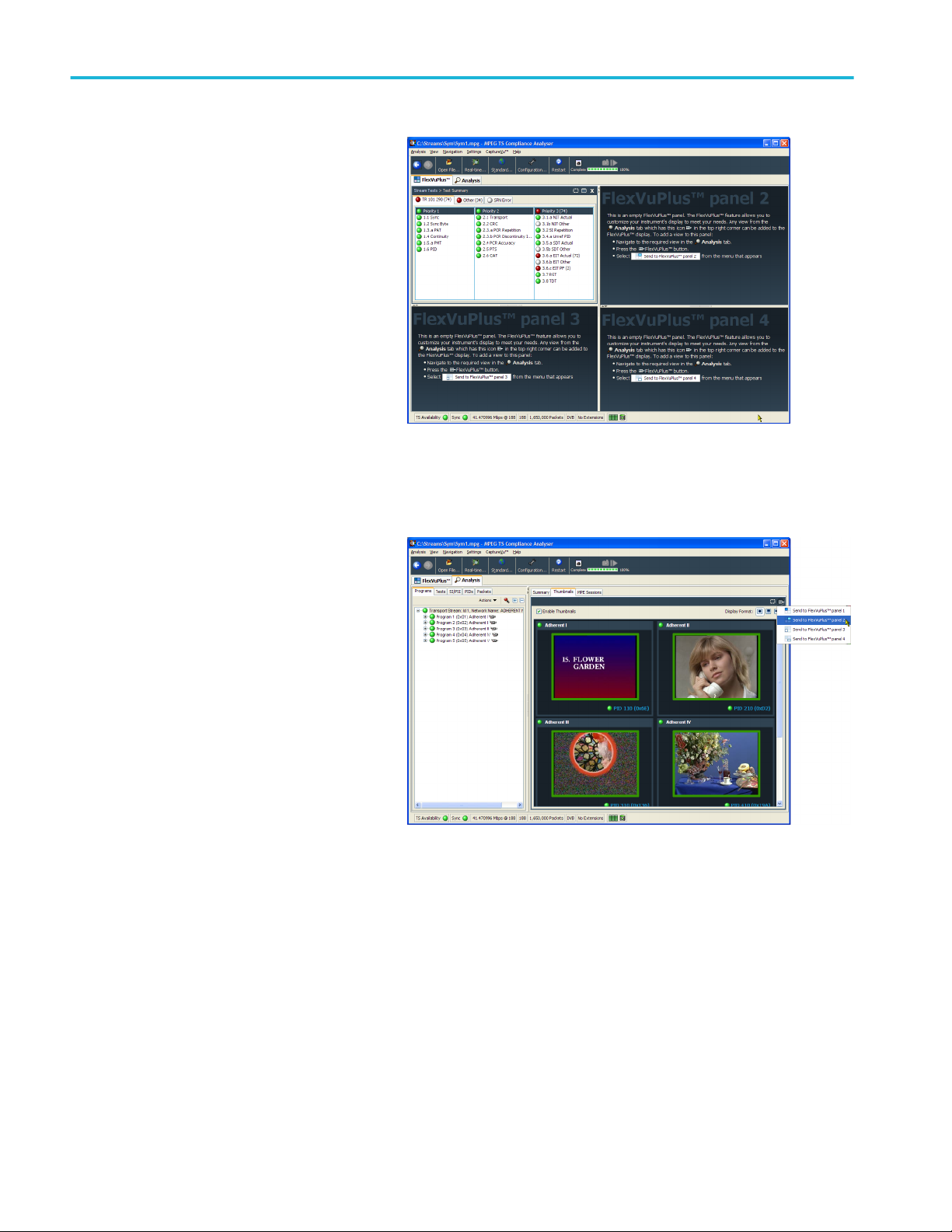
Procedures
3. The FlexVuPlus display now contains the
Test Summary view in panel 1.
Set up panel 2.
4. Select the Analysis tab and then the
Programs tab.
5. In the Thumbnails view, use the
FlexVuPlus panel select button to
replicate the view in panel 2.
58 MTSA-HW and MTSA-PC Quick Start User Manual

Procedures
6. The FlexVuPlus display now contains the
Thumbnail view in panel 2.
Set up panel 3.
7. Select the Analysis tab and then the
Tests tab.
8. In the Test Failures view, use the
FlexVuPlus panel select button to
replicate the view in panel 3.
MTSA-HW and MTSA-PC Quick Start User Manual 59

Procedures
9. The FlexVuPlus display now contains the
Test Failures view in panel 3.
Since only three panels are used in this
example, you can expand the thumbnails view
to fill the right side of FlexVuPlus™.
You can expand panel 2 vertically by selecting
the panel expand button.
(Similarly, you can expand panels horizontally
using the horizontal panel expand button.)
10. Expand panel 2 to display the complete
FlexVuPlus basic monitoring view.
To summarize, in this view you can immediately see the following:
■
In the Tests Summary view (FlexVuPlus panel 1), which tests have failed.
■
In the Test Failures view (FlexVuPlus panel 3), which tests have failed most recently.
■
In the Thumbnails view (FlexVuPlus panel 2), which elementary streams are currently carrying video content.
60 MTSA-HW and MTSA-PC Quick Start User Manual

Procedures
Multiple input monitoring
The MTSA-HW system is capable of monitoring multiple transport streams (on separate 10 G or PC NIC ports) using multiple
instances of the Transport Stream Compliance Analyzer.
1. Open Transport Stream Compliance
Analyzer. Tektronix MTSA > TS
Compliance Analyzer.
Select Real-time Analysis... in the TSCA
Analysis toolbar.
2. In the Select Real-time Interface dialog
screen, select an available input from the
Interfaces pull-down menu.
In the example the, ASI-3 input is
selected to monitor for this instance of the
TS Compliance Analyzer application.
The choices available are dependent on
the available optional inputs.
MTSA-HW and MTSA-PC Quick Start User Manual 61
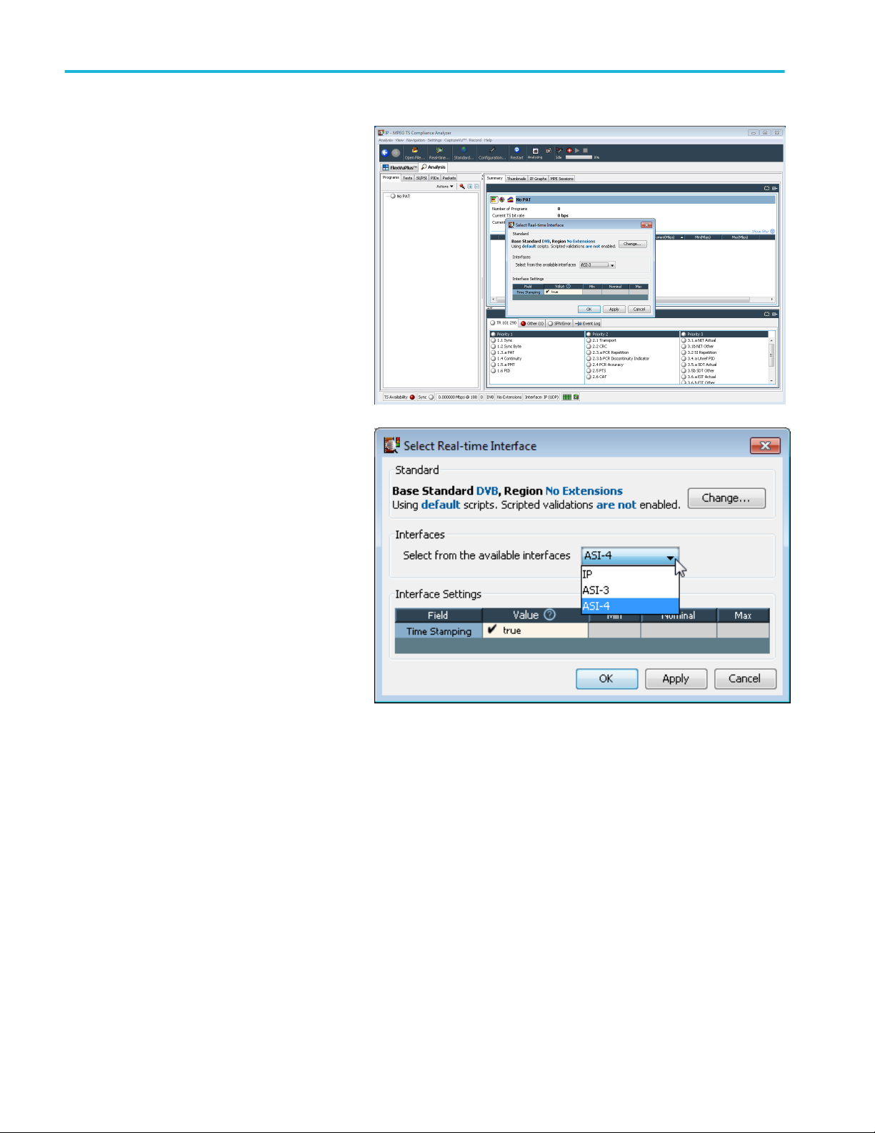
Procedures
3. Open a second instance of the Transport
Stream Compliance Analyzer. Tektronix
MTSA > TS Compliance Analyzer.
Select Real-time Analysis... in the TSCA
Analysis toolbar.
4. In the Select Real-time Interface dialog
screen, select an available input from the
Interfaces pull-down menu.
For this instance of the TS Compliance
Analyzer, ASI-4 input has been selected
to monitor.
62 MTSA-HW and MTSA-PC Quick Start User Manual

Accessories
Standard accessories
The following table lists the standard accessories that are shipped with the MTSA-HW instrument and MTSA-PC software:
Description Part number MTSA-HW MTSA-PC
Compliance certificate 001-1180-XX ■ ■
MTSA-HW and MTSA-PC Quick Start User Manual 071-3661-XX ■ ■
Supplemental information sheet; China ROHS 071-2185-XX ■ ■
Hardware key (dongle), USB NA ■
Power Cord (one of the following options)
■
Option A0 – North America
■
Option A1 – Universal Euro
■
Option A2 – United Kingdom
■
Option A3 – Australia
■
Option A4 – North America 240 V
NA ■
■
Option A5 – Switzerland
■
Option A6 – Japan
■
Option A10 – China
■
Option A11 – India
■
Option A99 – No power cord
Options and upgrades
Options
The following table lists the available hardware and software options that you can order with the MTSA-HW and MTSA-PC
systems. Accessories included with the options are also listed.
MTSA-HW and MTSA-PC Quick Start User Manual 63

Accessories
Option Description
Hardware options MTSA-HW ASI Add multiport ASI interface.
MTSA-HW 10GS Add 10 Gbase-SR dual optical port 10 Gb/s NIC. Includes short reach SFP+
modules (850 nm).
MTSA-HW SDR Add multifunction SDR RF interface with support for DVB-T, ISDB-T/Tb,
QAM A/B/ C and 8VSB. Includes level, BER, MER, constellation points.
MTSA-HW DS2 Add dual input DVB-S/S2 interface. Card supports dual port QPSK/8PSK or
single port 16APSK/32APSK demodulation. Includes level, BER, MER,
SNR, constellation points.
MTSA-HW RACK Add MTSA rackmount kit. Includes the rackmount slides and rails
Software Options MTSA-HW TSCA
MTSA-PC TSCA
MTSA-HW MUX
MTSA-PC MUX
MTSA-HW ESA
MTSA-PC ESA
MTSA-HW PBUFFA
MTSA-PC PBUFFA
MTSA-HW PQ
MTSA-PC PQ
MTSA-HW ALZRPK
MTSA-PC ALZRPK
MTSA-HW FLT
MTSA-PC FLT
Add real and deferred time Transport Stream Compliance Analyzer.
Includes real and deferred time TSCA for MPEG-2, ATSC1.0, DVB, ISDB-S,
ISDB-T, ISDB-TB. Carousel analysis and compliance for MPEG-2, DSM-CC,
DVB (INC. MHP), DTT (MHEG-5), ARIB. Closed Caption analysis, rendering
and alignment to CEA608, CEA708 and SCTE20/21 control commands.
Add Stream Multiplexer and Generator. Includes TS and ISDB-T/Tb
Multiplexer, ISDB-T Remux, TS Editor, Make Seamless, Carousel
Generator, and Tclips Test Streams; also includes HEVC stream generation
capabilities.
Add elementary stream analyzer. Includes support for VC1, AVC/H.264,
MPEG-4, MPEG-2, H.263, HEVC/H.265. Closed Caption analysis, rendering
and alignment to CEA608, CEA708 and SCTE20/21 control commands.
Add PES and T-STD Buffer Analyzers. Includes HEVC buffer analysis and
PES with AVC, HEVC and AC-3 codec analysis.
Add Picture Quality Analysis Software, Single and Double Ended. Includes
the PQA software with Option ESA to enable conversion of VC1, AVC/H.
264, HEVC/H. 265 source files to YUV for PQ Analysis.
Add Analyzer Software Bundle. Includes TSCA, ESA, MUX and PBUFFA.
Add floating license (all floating licenses include the same capabilities as
purchased); for multiple licenses, order multiple Option FLT.
MTSA-UP upgrade kits
The MTSA-UP upgrade kits are available to enhance the capabilities of the instrument and software after you purchase an
MTSA-HW or MTSA-PC system. Kits may contain software, hardware, or both.
Option Description
MTSA-UP
hardware upgrades
64 MTSA-HW and MTSA-PC Quick Start User Manual
MTSA-UP ASI Add multiport ASI interface.
MTSA-UP 10GS Add 10Gbase-SR dual optical port 10Gb/s NIC. Includes short reach SFP+
modules (850 nm).
MTSA-UP SDR Add multifunction SDR RF interface with support for DVB-T, ISDB-T/Tb,
QAM A/B/ C and 8VSB. Includes level, BER, MER, constellation points.
MTSA-UP DS2 Add dual input DVB-S/S2 interface. Card supports dual port QPSK/8PSK or
single port 16APSK/32APSK demodulation. Includes level, BER, MER,
SNR, constellation points.
MTSA-UP RACK Add MTSA rackmount kit. Includes rackmount slides and rails

Accessories
Option Description
MTSA-UP
software upgrades
MTSA-UP TSCA Add real and deferred time Transport Stream Compliance Analyzer.
Includes real and deferred time TSCA for MPEG-2, ATSC1.0, DVB, ISDB-S,
ISDB-T, ISDB-TB. Carousel analysis and compliance for MPEG-2, DSM-CC,
DVB (INC. MHP), DTT (MHEG-5), ARIB. Closed Caption analysis, rendering
and alignment to CEA608, CEA708 and SCTE20/21 control commands.
MTSA-UP MUX Add Stream Multiplexer and Generator. Includes TS and ISDB-T/Tb
Multiplexer, ISDB-T Remux, TS Editor, Make Seamless, Carousel
Generator, and Tclips Test Streams; also includes HEVC stream generation
capabilities.
MTSA-UP ESA Add elementary stream analyzer. Includes support for VC1, AVC/H.264,
MPEG-4, MPEG-2, H.263, HEVC/H.265. Closed Caption analysis, rendering
and alignment to CEA608, CEA708 and SCTE20/21 control commands.
MTSA-UP PBUFFA Add PES and T-STD Buffer Analyzers. Includes HEVC buffer analysis and
PES with AVC, HEVC and AC-3 codec analysis.
MTSA-UP PQ Add Picture Quality Analysis Software, Single and Double Ended. Includes
the PQA software with Option ESA to enable conversion of VC1, AVC/H.
264, HEVC/H. 265 source files to YUV for PQ Analysis.
MTSA-UP ALZRPK Add Analyzer Software Bundle. Includes TSCA, ESA, MUX and PBUFFA.
MTSA-UP FLT Add floating license (all floating licenses include the same capabilities as
purchased); for multiple licenses, order multiple Option FLT.
MTSA-HW and MTSA-PC Quick Start User Manual 65

Accessories
66 MTSA-HW and MTSA-PC Quick Start User Manual

User maintenance
This section describes general care and service procedures for the MTSA-HW instrument.
■
Preventive maintenance provides cleaning instructions
■
In case of problems provides some hints for troubleshooting startup errors
■
Returning the instrument for service gives instructions for repacking and shipping the instrument
General care
Protect the instrument from adverse weather conditions. The instrument is not waterproof.
CAUTION. To avoid damage to the instrument, do not expose it to sprays, liquids, or solvents.
Do not use chemical cleaning agents; they may damage the instrument. Avoid chemicals that contain benzene, toluene, xylene,
acetone, or similar solvents.
Preventative maintenance
Check the electrical performance and verify that the instrument accuracy is certified (calibrated) once a year.
Preventive maintenance mainly consists of periodic cleaning. Periodic cleaning reduces instrument breakdown and increases
reliability. You should clean the instrument as needed, based on the operating environment. Dirty conditions may require more
frequent cleaning than computer room conditions.
Cleaning the exterior
Clean the exterior surfaces of the instrument with a dry, lint-free cloth or a soft-bristle brush. If dirt remains, use a cloth or swab
dampened with a 75% isopropyl alcohol solution. A swab is useful for cleaning in narrow spaces around the controls and
connectors. Do not use abrasive compounds on any part of the instrument.
CAUTION. Avoid getting moisture inside the instrument during external cleaning and use only enough solution to dampen the
cloth or swab. Use a 75% isopropyl alcohol solution as a cleanser and rinse with deionized water.
Do not wash the front-panel On/Standby switch. Cover the switch while cleaning the instrument.
MTSA-HW and MTSA-PC Quick Start User Manual 67

User maintenance
In case of problems
This section addresses problems that you may encounter while using the test system. This section does not identify specific
problems related to performance verification or adjustments. The diagnostic procedures for the MTSA-HW system provided in
this section can help you isolate problems. For a performance verification procedure, refer to the MTSA-HW Specifications and
Performance Verification Technical Reference.
Power-on diagnostics run when you first power on the instrument to start the test system application. These diagnostics check
the operating system and hardware for correct operation. If error messages occur during the power-on diagnostics, there may be
a system error that prevents the MTSA-HW system software from starting.
The following table lists some of the symptoms of hardware problems (related to the operating system and peripheral devices)
and possible solutions.
Symptom Possible causes and recommended actions
Instrument does not power on Verify that the power cord is connected to the instrument and to
the power source.
Check that the instrument receives power when you push the
On/Standby switch; check that fan starts.
Check that power is available at the power source.
Contact your local Tektronix service center.
Instrument powers on but does not complete the power-on
sequence
Power-on diagnostics fail Contact your local Tektronix service center.
Instrument does not recognize accessories such as external
monitor, printer, or keyboard
Instrument will not power off with On/Standby switch Try powering off the instrument using the Windows
Make sure instrument boots from the hard disk drive.
Check that accessories are properly connected or installed.
Contact your local Tektronix service center.
10 shutdown procedure. If the instrument still does not power
off, use the task manager to close down tasks. Finally, try the
hard shutdown procedure; push and hold the On/Standby
switch for five seconds to power off the instrument.
Software problems
Your MTSA-HW instrument comes with software already installed. For any suspected software problems, try to isolate the
problem to the test system application software or to other installed software.
Many software problems are due to corrupt or missing software files. In most cases, the easiest way to solve software problems
is to reinstall the software. See GUID-78BED516-B6F8-4C93-8038-172CF5428567#GUID-78BED516-
B6F8-4C93-8038-172CF5428567.
If you suspect networking problems, see Network troubleshooting on page 8.
68 MTSA-HW and MTSA-PC Quick Start User Manual

User maintenance
Hardware problems
Hardware problems can have several causes. Review the installation instructions in this manual to verify that you have properly
installed the instrument. There are no user serviceable parts in the MTSA-HW system, so you should contact your local Tektronix
Service representative if you have a hardware problem.
Returning the instrument for service
When repacking the instrument for shipment, use the original packaging. If the packaging is unavailable or unfit for use, contact
your local Tektronix representative to obtain new packaging.
1. Seal the shipping carton with an industrial stapler or strapping tape. Before returning the instrument for service, contact the
Service Center to get an RMA (return material authorization) number, and any return or shipping information you may need.
2. If the instrument is being shipped to a Tektronix Service Center, enclose the following information:
■
The RMA number.
■
The owner's address.
■
Name and phone number of a contact person.
■
Type and serial number of the instrument.
■
Reason for returning.
■
A complete description of the required service.
3. Mark the address of the Tektronix Service Center and the return address on the shipping carton in two prominent locations.
MTSA-HW and MTSA-PC Quick Start User Manual 69

User maintenance
70 MTSA-HW and MTSA-PC Quick Start User Manual

Index
A
Accessories, 63
Add elementary streams, 35
Analyzer applications, 22
Applications, 22
B
Basic requirements, 8
Before installation, 1
C
Check package contents, 1
Cleaning
exterior, 67
Connectors
cards, 6
front, 4
front panel, 4
rear panel, 5
Controls, 3, 4
Create a new stream, 29
D
Display
FlexVu, 57
Dongle, 15
Duplex operation, 24
FlexVuPlus, 57
Floating license
installation, 9
operation, 27
G
General care, 67
Generator applications, 22
H
Hardware problems, 69
I
Incorrect default gateway,
Incorrect IP address,
Incorrect subnet mask,
Inputs
selecting, 61
Installation
network, 8
operating requirements, 1
standalone, 15
system requirements, 15
IP parameters, 9
L
Loopback, 25
E
Elementary stream acquisition, 34
Elementary Stream analyzer
using, 54
Elementary streams, 35
ES Analyzer
using, 54
Examine stream content, 42
M
Maintenance, 67
MTSA applications, 21
MTSA-UP upgrade kits, 64
Multi input monitoring, 61
Multiple, 61
Multiplexer
using, 29
F
Finding IP addresses,
MTSA-HW and MTSA-PC Quick Start User Manual 71

Index
N
Network installation, 8
Network troubleshooting, 8
O
Operating requirements, 1
Operation, 21
Option card connectors, 6
Option FLT, 9, 27
Option key wizard, 19, 24
Options
hardware, 63
software, 63
P
Packaging, 69
PES, 46
PES analyzer
using, 46
Pinging a host machine,
Player applications, 23
Power
off, 8
on, 8
requirements, 1
supplying, 7
Preventative maintenance, 67
Procedures
setting up FlexVu, 57
Product description, 21
Setting up loopback, 25
Setting up the FlexVu display, 57
Shipping the instrument, 69
Software
applications list, 22
problems, 68
Standalone
installation, 15
system requirements, 15
Standard accessories, 63
Start menu, 24
T
T-STD buffer analyzer
using, 49
Tracing the route,
Troubleshooting
power-on failures, 68
Troubleshooting procedures, 9
TSCA
application icons, 22
duplex setup, 25
using, 42
U
Upgrade kits, 64
Utility applications, 23
V
R
Repackaging for shipment, 69
VLC media player
installation, 20
S
Selecting inputs, 61
72 MTSA-HW and MTSA-PC Quick Start User Manual
 Loading...