

Page 1

Instructions
MTS4UP UPG, GBE, CF, EP, QB2, or VS
MTS400 Series Upgrade Kits
075-0912-01
Warning
The servicing instructions are for use by qualified
personnel only. To avoid personal injury, do not
perform any servicing unless you are qualified to
do so. Refer to all safety summaries prior to
performing service.
www.tektronix.com
*P075091201*
075091201
Page 2

Copyright © Tektronix. All rights reserved. Licensed software products are owned by Tektronix or its subsidiaries or
suppliers, and are protected by national copyright laws and international treaty provisions.
Tektronix products are covered by U.S. and foreign patents, issued and pending. Information in this publication supercedes
that in all previously published material. Specifications and price change privileges reserved.
TEKTRONIX and TEK are registered tradem arks of Tektronix, Inc.
Contacting Tektronix
Tektronix, Inc.
14200 SW Karl Braun Drive
P.O. Box 500
Beaverton, OR 97077
USA
For product information, sales, service, and technical support:
H In North America, call 1-800-833-9200.
H Worldwide, visit www.tektronix.com to find contacts in your area.
Page 3

Table of Contents
General Safety Summary iii...................................
Service Safety Summary v....................................
Kit Description 1............................................
Upgrade Kits Covered by These Instructions 1..........................
Products 2.......................................................
Minimum Tool and Equipment List 2..................................
Kit Parts Lists 3...................................................
Upgrade Instructions 7.......................................
Option UPG Software Upgrade Instructions 7...........................
Verify Operation 12.................................................
Upgrading Hardware 12.............................................
MTS4UP GBE Upgrade Instructions 14.................................
MTS4UP CF, EP, QB2, or VS Upgrade Instructions 15.....................
Replace the Cabinet 18..............................................
Restore the Operating System 19......................................
Software Upgrade Instructions 26......................................
Verify Operation 32.................................................
Software Key Upgrade Instructions 32...........................
Verify Operation 32.................................................
MTS4UP MTS400 Series Upgrade Kits
i
Page 4

Table of Contents
ii
MTS4UP MTS400 Series Upgrade Kits
Page 5

General Safety Summary
Review the following safety precautions to avoid injury and prevent damage to
this product or any products connected to it.
To avoid potential hazards, use this product only as specified.
Only qualified personnel should perform service procedures.
ToAvoidFireor
Personal Injury
Use Proper Power Cord. Use only the power cord specified for this product and
certified for the country of use.
Ground the Product. This product is grounded through the grounding conductor
of the power cord. To avoid electric shock, the grounding conductor must be
connected to earth ground. Before making connections to the input or output
terminals of the product, ensure that the product is properly grounded.
Ground Equipment connected to the Product. Ensure that any equipment
connected to this product is grounded and at the same potential.
Observe All Terminal Ratings. To avoid fire or shock hazard, observe all ratings
and markings on the product. Consult the product manual for further ratings
information before making connections to the product.
Power Disconnect. The power cord disconnects the product from the power
source. Do not block the power cord; it must remain accessible to the user at all
times.
Do Not Operate Without Covers. Do not operate this product with covers or panels
removed.
Use Proper Fuse. Use only the fuse type and rating specified for this product.
Avoid Exposed Circuitry. Do not touch exposed connections and components
when power is present.
Do Not Operate With Suspected Failures. If you suspect there is damage to this
product, have it inspected by qualified service personnel.
Do Not Operate in Wet/Damp Conditions.
Do Not Operate in an Explosive Atmosphere.
Keep Product Surfaces Clean and Dry.
Provide Proper Ventilation. Refer to the manual’s installation instructions for
details on installing the product so it has proper ventilation.
MTS4UP MTS400 Series Upgrade Kits
iii
Page 6

General Safety Summary
Terms in this Manual
Symbols and Terms
on the Product
These terms may appear in this manual:
WARNING. Warning statements identify conditions or practices that could result
in injury or loss of life.
CAUTION. Caution statements identify conditions or practices that could result in
damage to this product or other property.
These terms may appear on the product:
H DANGER indicates an injury hazard immediately accessible as you read the
marking.
H WARNING indicates an injury hazard not immediately accessible as you
read the marking.
H CAUTION indicates a hazard to property including the product.
The following symbols may appear on the product:
CAUTION
Refer to Manual
Protective Ground
(Earth) Terminal
iv
MTS4UP MTS400 Series Upgrade Kits
Page 7

Service Safety Summary
Only qualified personnel should perform service procedures. Read this Service
Safety Summary, and the General Safety Summary located in the RSA6100A
Service manual (Tektronix part number 071--1914--xx) before performing any
service procedures.
Do Not Service Alone. Do not perform internal service or adjustments of this
product unless another person capable of rendering first aid and resuscitation is
present.
Disconnect Power. To avoid electric shock, switch off the instrument power, then
disconnect the power cord from the mains power.
Use Care When Servicing With Power On. Dangerous voltages or currents may
exist in this product. Disconnect power, remove battery (if applicable), and
disconnect test leads before removing protective panels, soldering, or replacing
components.
To avoid electric shock, do not touch exposed connections.
MTS4UP MTS400 Series Upgrade Kits
v
Page 8

Service Safety Summary
vi
MTS4UP MTS400 Series Upgrade Kits
Page 9

Kit Description
This document provides instructions for performing hardware and/or software
and option key upgrades on the following Tektronix products:
H MTS400 Series MPEG Test System
H MTS4SA MPEG Test System
Upgrade Kits Covered by These Instructions
H MTS4UP UPG -- This kit provides a software upgrade for your MTS4xx.
This upgrade is included with all of the hardward updates, or may be ordered
separately.
As the user of an MTS400 Series MPEG Test System you will be familiar with
the software key (or dongle) that must be attached to your unit before you can
open any of the MTS applications. Two styles of software key are available, each
performs the same function: parallel port or (MTS4SA only) USB. The option
key string supplied with this upgrade kit is generated using the serial number of
the software key and the list of options to be licensed.
NOTE. Only the software applications already installed on your MPEG test
system will be available after the upgrade. If additional applications are
required, contact your Tektronix representative.
H MTS4UP GBE -- This kit adds a Gigabit Ethernet interface and IP Analysis
software to your MTS400 or MTS430 (SFP required). This kit may be
combined with any of the following hardware upgrade kits.
There are also four optical length input options available with option GbE:
H MTS4UP LX -- Adds a 1000Base-LX wavelength optical port with LC
connector (single mode 1310 nm)
H MTS4UP SX -- Adds a 1000Base--SX short wavelength optical port with
LC connector (multimode 850 nm).
H MTS4UP ZX -- Adds a 1000Base-ZX wavelength optical port with LC
connector (multimode 1550 nm).
H MTS4UP CU -- adds a 1000Base-T electrical port with RJ45 connector.
MTS4UP MTS400 Series Upgrade Kits
1
Page 10

Kit Description
Products
H MTS4UP CF -- This kit adds a COFDM DVB-T interface to your MTS400
Series instrument. This kit may only be combined with the MTS4UP GBE
kit.
H MTS4UP EP -- This kit adds a QPSK/8PSK interface to your MTS400
Series instrument. This kit may only be combined with the MTS4UP GBE
kit.
H MTS4UP QB2 -- This kit adds a QAM B interface to your MTS400 Series
instrument. This kit may only be combined with the MTS4UP GBE kit.
H MTS4UP VS -- This kit adds an 8VSB interface to your MTS400 Series
instrument. This kit may only be combined with the MTS4UP GBE kit.
These kits apply to the MTS400 and MTS430 MPEG Test Systems. The
MTS4UP UPG software upgrade can also be used with an MTS4SA installation.
Minimum Tool and Equipment List
No tools are required to perform the software upgrade. The hardware upgrades
will require:
Required tools and equipment Part number
Anti-static wrist strap Standard equipment
Screwdriver handle with T-15 TORX tip Standard equipment
2
MTS4UP MTS400 Series Upgrade Kits
Page 11

Kit Parts Lists
Kit Description
MTS4UP UPG
MTS4UP GBE
The MTS4UP UPG software upgrade kit contains these parts:
Quantity Part number Description
1Each 020-2654-xx DOCUMENTATION KIT; ENGLISH GETTING STARTED
MANUAL W/DOCUMENTATION CD-ROM; MTS400
SERIES
1 Each 063-3814-xx SOFTWARE PKG; APPLICATION INSTALL CD-ROM;
MTS400 SERIES
1Each NS IMPORTANT DOCUMENTS ENVELOPE, WITH PRODUCT
OPTION KEY
1 Each 071-1507-xx MANUAL, TECH; USER, VOLUME 1 AND 2; MTS400
SERIES
1 Each 071-1726-xx MANUAL, TECH; RELEASE NOTES; MTS400 SERIES
1Each 075-0912-01 KIT INSTRUCTION; MTS4UP UPG, GBE, CF, EP, QB2, or
VS
NS - Not Saleable
The MTS4UP GBE upgrade kit contains all the parts listed for the
MTS4UP UPG software upgrade kit, and these additional parts:
Quantity Part number Description
1Each 672--6300--xx ASSEMBLY, CHEETAH II SPE--0028--03--002 AND
OPTICAL EAGLE BOARD; PMC--0005--03--001, SAFETY
CONTROLLED
1 Each 063--3971--xx SOFTWARE PKG; MICROSOFT WINDOWS XP
PROFESSIONAL,W/SP2B RECOVERY MEDIA AND NERO
BURNING SOFTWARE, VER 1.4;MTS400 SERIES
2Each 211--0722--00 SCREW,CAP; 6--32 X 0.75,HEX SKT,SST
MTS4UP MTS400 Series Upgrade Kits
3
Page 12

Kit Description
MTS4UP CF
MTS4UP EP
The MTS4UP CF upgrade kit contains all the parts listed for the MTS4UP UPG
software upgrade kit, and these additional parts:
Quantity Part number Description
1Each 672--1780--xx TESTED SET, BASE BAND AND COFDM; SAFETY
CONTROLLED
1 Each 174--5336--xx CABLE ASSEMBLY;5--PIN;RS232 INTERFACE BETWEEN
SBC AND RF CARD; 12.5 INCH L +/-- .500; SAFETY
CONTROLLED
1 Each 174--5135--xx CABLE ASSY;RF , BNC TO BNC;75 OHM
1 Each 015--0688--xx ADAPTER, RF; BNC JACK TO F PLUG
1 Each 063--3971--xx SOFTWARE PKG; MICROSOFT WINDOWS XP
PROFESSIONAL,W/SP2B RECOVERY MEDIA AND NERO
BURNING SOFTWARE, VER 1.4;MTS400 SERIES
2Each 211--0722--00 SCREW,CAP; 6--32 X 0.75,HEX SKT,SST
The MTS4UP EP upgrade kit contains all the parts listed for the MTS4UP UPG
software upgrade kit and these additional parts:
Quantity Part number Description
1Each 672--1781--xx TESTED SET, BASE BAND AND 8PSK; SAFETY
CONTROLLED
1 Each 174--5336--xx CABLE ASSEMBLY;5--PIN;RS232 INTERFACE BETWEEN
SBC AND RF CARD; 12.5 INCH L +/-- .500; SAFETY
CONTROLLED
1 Each 174--5135--xx CABLE ASSY;RF , BNC TO BNC;75 OHM
1 Each 063--3971--xx SOFTWARE PKG; MICROSOFT WINDOWS XP
PROFESSIONAL,W/SP2B RECOVERY MEDIA AND NERO
BURNING SOFTWARE, VER 1.4;MTS400 SERIES
2Each 211--0722--00 SCREW,CAP; 6--32 X 0.75,HEX SKT,SST
4
MTS4UP MTS400 Series Upgrade Kits
Page 13

Kit Description
MTS4UP QB2
MTS4UP VS
The MTS4UP QB2 upgrade kit contains all the parts listed for the
MTS4UP UPG software upgrade kit and these additional parts:
Quantity Part number Description
1Each 672--1782--xx TESTED SET, BASE BAND AND QB2; SAFETY
CONTROLLED
1 Each 174--5336--xx CABLE ASSEMBLY;5--PIN;RS232 INTERFACE BETWEEN
SBC AND RF CARD; 12.5 INCH L +/-- .500; SAFETY
CONTROLLED
1 Each 174--5135--xx CABLE ASSY;RF , BNC TO BNC;75 OHM
1 Each 063--3971--xx SOFTWARE PKG; MICROSOFT WINDOWS XP
PROFESSIONAL,W/SP2B RECOVERY MEDIA AND NERO
BURNING SOFTWARE, VER 1.4;MTS400 SERIES
2Each 211--0722--00 SCREW,CAP; 6--32 X 0.75,HEX SKT,SST
The MTS4UP VS upgrade kit contains all the parts listed for the MTS4UP UPG
software upgrade kit, and these additional parts:
Quantity Part number Description
1Each 672--1783--xx TESTED SET, BASE BAND AND 8VSB; SAFETY
CONTROLLED
1 Each 174--5336--xx CABLE ASSEMBLY;5--PIN;RS232 INTERFACE BETWEEN
SBC AND RF CARD; 12.5 INCH L +/-- .500; SAFETY
CONTROLLED
1 Each 174--5135--xx CABLE ASSY;RF , BNC TO BNC;75 OHM
1 Each 015--0688--xx ADAPTER, RF; BNC JACK TO F PLUG
1 Each 063--3971--xx SOFTWARE PKG; MICROSOFT WINDOWS XP
PROFESSIONAL,W/SP2B RECOVERY MEDIA AND NERO
BURNING SOFTWARE, VER 1.4;MTS400 SERIES
2Each 211--0722--00 SCREW,CAP; 6--32 X 0.75,HEX SKT,SST
MTS4UP MTS400 Series Upgrade Kits
5
Page 14

Kit Description
6
MTS4UP MTS400 Series Upgrade Kits
Page 15

Upgrade Instructions
These instructions are for personnel who are familiar with servicing the product.
If you need further details for disassembling or reassembling the product, refer to
the appropriate product manual. Contact your nearest Tektronix, Inc., Service
Center or Tektronix Factory Service for installation assistance.
CAUTION. To prevent static discharge damage, service the product only in a
static-free environment. Observe standard handling precautions for static-sensitive devices while installing this kit. Always wear a grounded wrist strap,
grounded foot strap, and static resistant apparel while installing this kit.
If you are installing an MTS4UP UPG software upgrade only, follow the
procedure below. If you are installing any of the hardware options, go to
Upgrading Hardware on page 12.
Option UPG Software Upgrade Instructions
Perform the following steps to upgrade the MTS400 Series software and
software key:
1. Ensure that the instrument or PC to be upgraded is switched on and has
completed the start-up process.
2. Ensure that the software key (dongle) is attached to your instrument.
3. Insert the MTS400 Series Application Install CD-ROM supplied with this kit
into the CD-ROM drive of the instrument or PC to be upgraded. The
CD-ROM will autostart and display the Welcome screen shown in Figure 1.
NOTE. If the CD-ROM fails to autostart, use Windows Explorer to locate and run
the following file on the CD-ROM: start.exe.
4. Click Next to initiate the upgrade process (see Figure 1).
MTS4UP MTS400 Series Upgrade Kits
7
Page 16

Upgrade Instructions
Figure 1: InstallShield Wizard welcome screen
5. Allow the installation process to proceed. The average installation time is
approximately five minutes.
NOTE. A number of dialog boxes are displayed during the installation process.
Normally, no user intervention is required.
6. When the upgrade installation is complete, the Update Complete screen is
displayed as shown in Figure 2.
8
MTS4UP MTS400 Series Upgrade Kits
Page 17

Upgrade Instructions
Figure 2: InstallShield Wizard update complete screen
7. Select the Yes, I want to restart my computer now option, and then click
Finish. The instrument or PC will shut down and then restart.
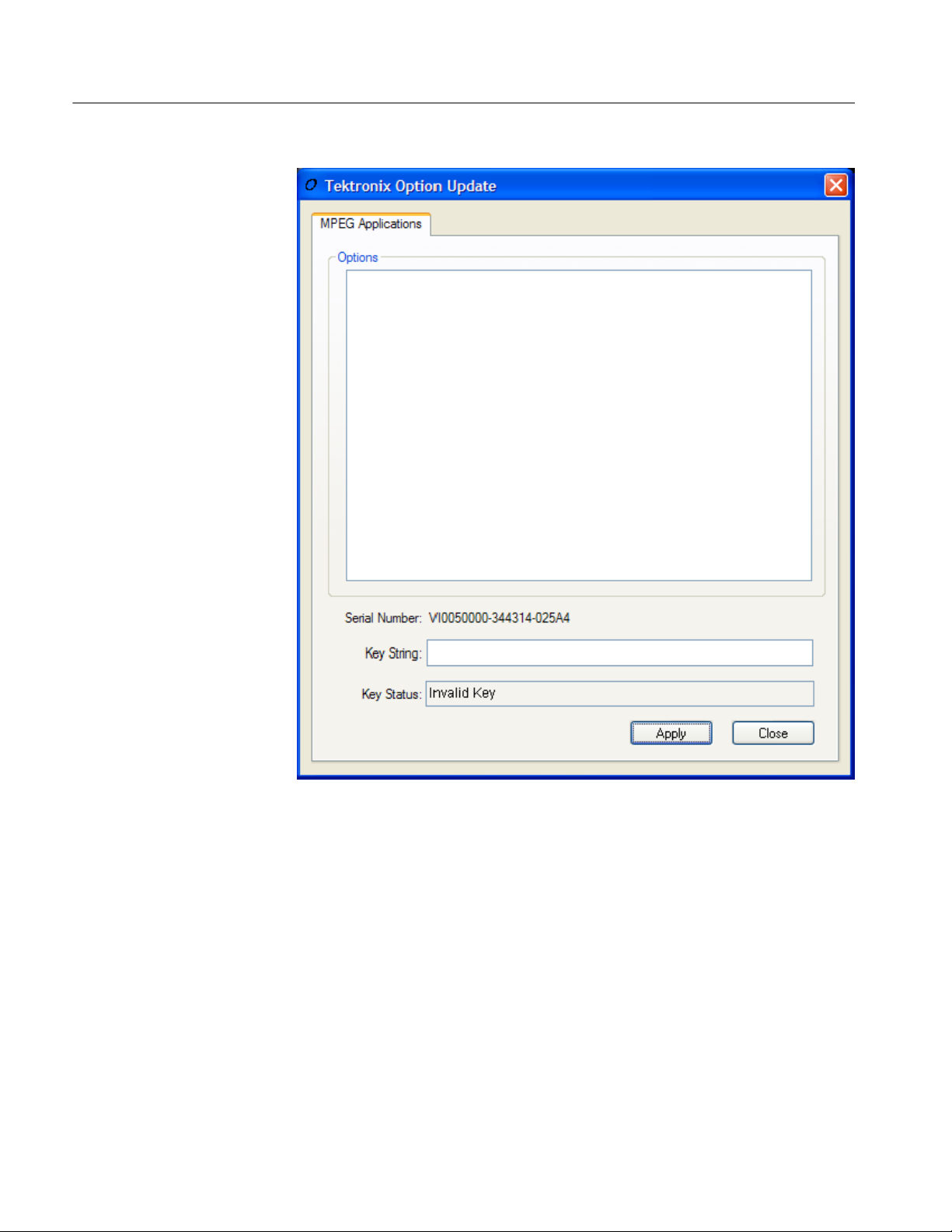
8. When the unit has completed the start-up process, the Tektronix Option
Update wizard will start automatically (see Figure 3).
MTS4UP MTS400 Series Upgrade Kits
9
Page 18

Upgrade Instructions
10
Figure 3: Tektronix Option Update Wizard - Initial view
Note that the Serial Number of the software key has been detected, but the
Key Status is invalid because no KeyString has been entered.
9. In the Tektronix Option Update dialog box, enter the Option Key String,
found on the Product Option Key label supplied with these upgrade
instructions, in the Key String field. Click Apply.
MTS4UP MTS400 Series Upgrade Kits
Page 19

Upgrade Instructions
Figure 4: Tektronix Option Update Wizard - Complete
10. Inspect and verify the list of licensed options (see Figure 24).
11. Close the Tektronix Option Update wizard.
12. Peel the backing off of the Product Option Key label and apply it to the
instrument rear panel, as shown in Figure 5. If there is already an option key
label on the rear panel apply the new one over the old one.
The upgrade is now complete.
MTS4UP MTS400 Series Upgrade Kits
11
Page 20

Upgrade Instructions
Verify Operation
Upgrading Hardware
Accessing the Module Bay
Figure 5: Product Option key label location
To verify operation of the upgraded applications, open and close each installed
application in turn.
If any licensed application fails to open correctly, contact your Tektronix
representative.
Use the following procedure to install any of the hardware upgrades.
WARNING. To avoid electric shock, switch off the instrument power, then
disconnect the power cord from the mains power. Failure to do so can cause
injury or death.
12
In order to install any of the hardware upgrades you must first remove the
cabinet and the circuit board retaining plate. Follow these steps to access the
module bay:
1. Power down the system and unplug the power cord.
MTS4UP MTS400 Series Upgrade Kits
Page 21

Upgrade Instructions
2. Disconnect any cables from the rear panel. Note the location of any cables
for reinstallation.
3. Install the protective cover on the front of the instrument and place the
cabinet on the working surface with the rear panel facing up.
4. Remove the handle from the side of the instrument and remove the four feet
from the rear of the instrument. Retain the screws for reinstallation.
WARNING. To prevent damage to the EMI shielding and injury to yourself, use
care when touching the EMI shielding strips around the front of the chassis. If
you accidentally bend the “fingers” of the strip, it could create sharp protruding
edges, which may cut you as you handle the chassis.
5. Use a wrench as a lever to pry the cabinet loose from the chassis. Loosen
each side alternately until the cabinet is released from the EMI gasket.
6. Slide the cabinet up and off the chassis.
7. Set the instrument onto the work surface so the bottom is down, as shown in
Figure 6.
8. Remove the five T-15 screws securing the circuit board retaining plate to the
chasis and lift it away (see Figure 6).
MTS4UP MTS400 Series Upgrade Kits
13
Page 22

Upgrade Instructions
Remove
screws (5)
Circuit board
retaining plate
Figure 6: Removing the circuit board retaining plate
If you are installing an MTS4UP GBE Gigabit Ethernet input upgrade, with or
without any of the other hardware upgrades, continue with the process below.
If you are installing an MTS4UP CF, MTS4UP EP, MTS4UP QB2, or MTS4UP
VS upgrade without an MTS4UP GBE, go to page 15.
MTS4UP GBE Upgrade Instructions
Perform the following steps to install the MTS4UP GBE Gigabit Ethernet
interface:
1. Turn the instrument so the rear panel is facing you.
2. Remove the two blank panels covering slots 2 and 3.
3. Align the Gigabit Ethernet interface module over the slot 2 connector, with
the card edge engaged in the slot 2 card guide, and slide the module down
into slot 2 (see Figure 7).
14
MTS4UP MTS400 Series Upgrade Kits
Page 23

Upgrade Instructions
4. Press down firmly to engage the module into the connector (see Figure 7).
Figure 7: Gigabit Ethernet module in place
5. Secure the Gigabit Ethernet module in place, using the screws that held the
slot 2 blank panel in place.
6. Replace the slot 3 blank panel.
If you are installing any of the other hardware options at this time continue with
the following procedure. Otherwise, go to Restore the Operating System on
page 19.
MTS4UP CF, EP, QB2, or VS Upgrade Instructions
These hardware upgrades are all installed in a similar manner, and must be
installed in slot 4.
1. Remove the three blank panels covering slots 4, 5, and 6.
2. Align the hardware upgrade module over the slot 4 connector, with the edge
of the long card engaged in the slot 4 card guide, and slide the module down
into slot 4.
3. Press down firmly to engage the module into the slot 4 connector (see
Figure 8).
MTS4UP MTS400 Series Upgrade Kits
15
Page 24

Upgrade Instructions
Figure 8: Hardware upgrade module installed in slot 4
4. Secure the hardware upgrade module in place, using the screws that held the
slot 4 and 5 blank panels in place.
5. Attach the 2x5 connector end of the interface cable provided in the kit to the
COM2 connector on the controller board in slot 11, as shown in Figure 9.
This connector is keyed and can only be installed one way.
6. Connect the other end of the interface cable to J14 on the hardware upgrade
module, as shown in Figure 10.
16
MTS4UP MTS400 Series Upgrade Kits
Page 25

Upgrade Instructions
Figure 9: Interface cable connected to controller board
Figure 10: Interface cable connected to the hardware upgrade module
MTS4UP MTS400 Series Upgrade Kits
17
Page 26

Upgrade Instructions
Replace the Cabinet
Replace the circuit board retaining plate and the cabinet by reversing the
Accessing the Module Bay instructions on page 12.
CAUTION. To prevent damage to the instrument, make sure that the internal
cables do not catch when you slide the cabinet back onto the chassis. Make sure
that the edges of the cabinet go under the retaining tabs around the front of the
chassis. You may have to push on the side of the cabinet to get all of the edges
under the tabs and over the EMI gasket.
At the rear of the chassis, you may have to push on the sides of the cabinet to get
the rear of the cabinet to fit over the edges of the chassis and EMI gasket.
18
MTS4UP MTS400 Series Upgrade Kits
Page 27
Restore the Operating System
After installing the hardware upgrade, you must restore the operating system to
install the new application software and drivers required for the hardware.
CAUTION. To avoid losing access to your licensed applications, you must use the
MTS400 Series system Recovery media supplied with this upgrade kit.
Upgrade Instructions
MTS400 Series system
Operating System Restore
To restore the MTS400 Series system operating system, use the following steps.
This restore process is effective only if the hard disk drive is still good. The
process will restore the operations system and the application software. (The
process should take less than one hour.)
CAUTION. To prevent data loss, back up your hard drive before you restore the
MTS400 Series system. All data on the hard drive will be destroyed during the
system restore process.
1. Start the MTS400 Series system.
2. During the boot process, insert the MTS400 Series System Operating System
Restore DVD in the CD--ROM drive. The system will autostart the recovery
application when the boot process finishes, see Figure 11.
MTS4UP MTS400 Series Upgrade Kits
19
Page 28

Upgrade Instructions
Figure 11: Operating system recovery application
3. Press the “1” key to begin the system restore process. The Acquiring
Device... dialog box will appear briefly and display a progress bar.
4. When the system restore is complete, press any key and then press the “4”
key, see Figure 12.
20
MTS4UP MTS400 Series Upgrade Kits
Page 29

Upgrade Instructions
Reinstate the SCSI Drives
Figure 12: Restore Complete
5. When prompted, press the “Y” key to reboot the instrument. Remove the
DVD from the CD--ROM drive while the system is rebooting.
6. On startup, the system will prompt you to set up Windows XP. Follow the
onscreen procedure, accepting the license agreement and defaults where
necessary.
NOTE. The screen will go blank for a few minutes during this process. Do not
turn the instrument off.
7. The system will restart on its own.
After restoring the operating system, confirm that the SCSI drives (drives E and
F) have been recognized by the system. Figure 13 shows the drives in Windows
Explorer.
MTS4UP MTS400 Series Upgrade Kits
21
Page 30
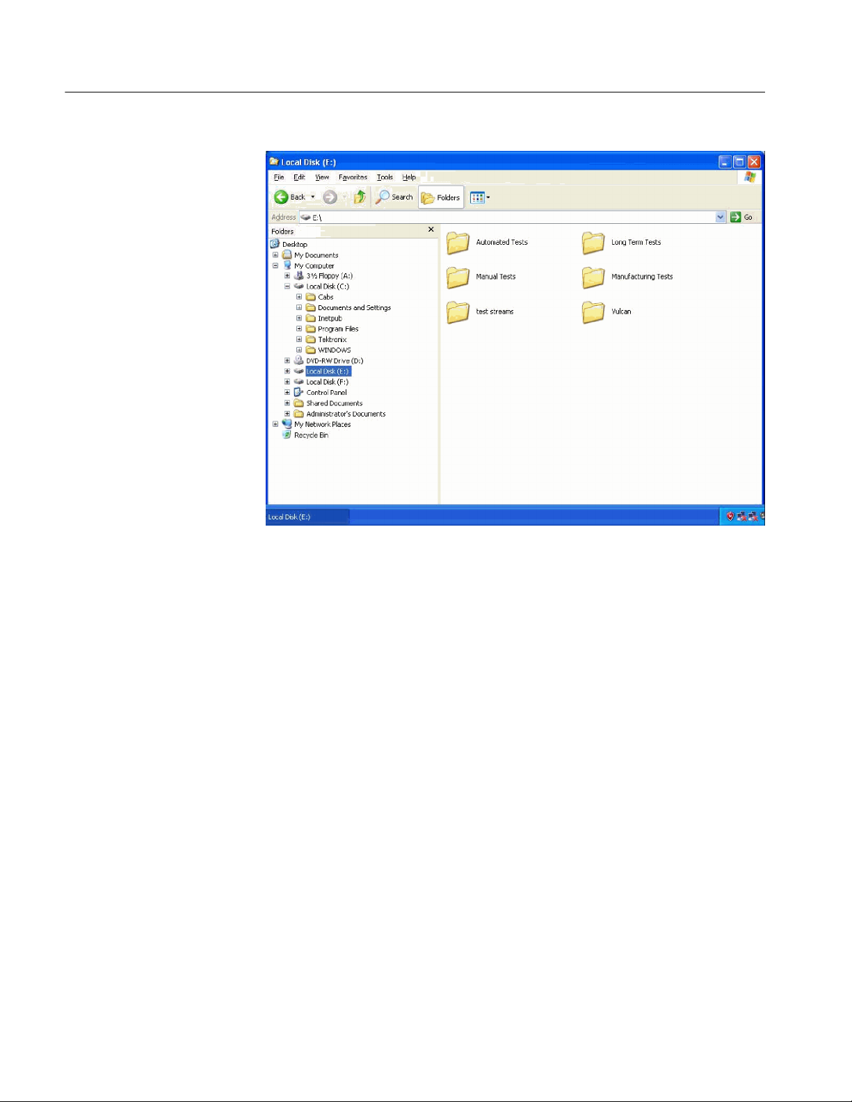
Upgrade Instructions
Figure 13: SCSI drives automatically recognized
If drives E and F are not listed in Windows Explorer, complete the following
procedure to allow them to be recognized by the system.
1. Open the Windows Disk Management window (Start > Control Panel >
Performance and Maintenance > Administrative Tools > Computer
Management > Storage > Disk management).
Note that Disk 0 and Disk 1 are described as Foreign, as shown in
Figure 14.
22
MTS4UP MTS400 Series Upgrade Kits
Page 31

Upgrade Instructions
Figure 14: Computer Management - SCSI drives, foreign
2. Right--clickonDisk0orDisk1andselectImport Foreign Disks... from
the shortcut menu (see Figure 15).
MTS4UP MTS400 Series Upgrade Kits
23
Page 32

Upgrade Instructions
Figure 15: Select Import Foreign Disks...
3. In the Import Foreign Disks dialog box, ensure that the disk group is
checked and select OK. See Figure 16.
Figure 16: Import Foreign Disks dialog box
4. In the Foreign Disk Volumes dialog box, select OK. See Figure 17.
24
MTS4UP MTS400 Series Upgrade Kits
Page 33

Upgrade Instructions
Figure 17: Foreign Disk Volumes dialog box
5. This takes a little time. Wait until the drives appear in the upper window, as
shown in Figure 18.
Figure 18: SCSI drives manually recognized
If the SCSI drives fail to import, follow this procedure:
1. Copy the file “SCSIKeyDel.reg” from the restore DVD to your C: drive.
2. Double click the file to initiate it.
3. When prompted to add information to the registry, press “Yes.”
4. When the information successfully entered message appears, press “OK.”
MTS4UP MTS400 Series Upgrade Kits
25
Page 34

Upgrade Instructions
5. Reboot the MTS400 platform.
6. Import the SCSI drives again, using the procedure above, starting on
page 22.
This completes the MTS400 Operating System Restore Procedure. Close the
Computer Management window. You must now upgrade the software, as
described in the following procedure.
Software Upgrade Instructions
Perform the following steps to upgrade the MTS400 Series software and
software key:
1. Ensure that the instrument or PC to be upgraded is switched on and has
completed the start-up process.
2. Ensure that the software key (dongle) is attached to your instrument.
3. Insert the MTS400 Series Application Install CD-ROM supplied with this kit
into the CD-ROM drive of the instrument or PC to be upgraded. The
CD-ROM will autostart and display the Welcome screen shown in Figure 19.
NOTE. If the CD-ROM fails to autostart, use Windows Explorer to locate and run
the following file on the CD-ROM: start.exe.
4. Click Next.
H If you have not installed Option GBE, just accept the defaults during the
upgrade process and reboot when complete. Go to step 13 on page 29.
H If you have installed Option GBE the Setup Type dialog box will be
displayed, which allows you to select the type of installation (see
Figure 20). Continue to step 5.
26
MTS4UP MTS400 Series Upgrade Kits
Page 35
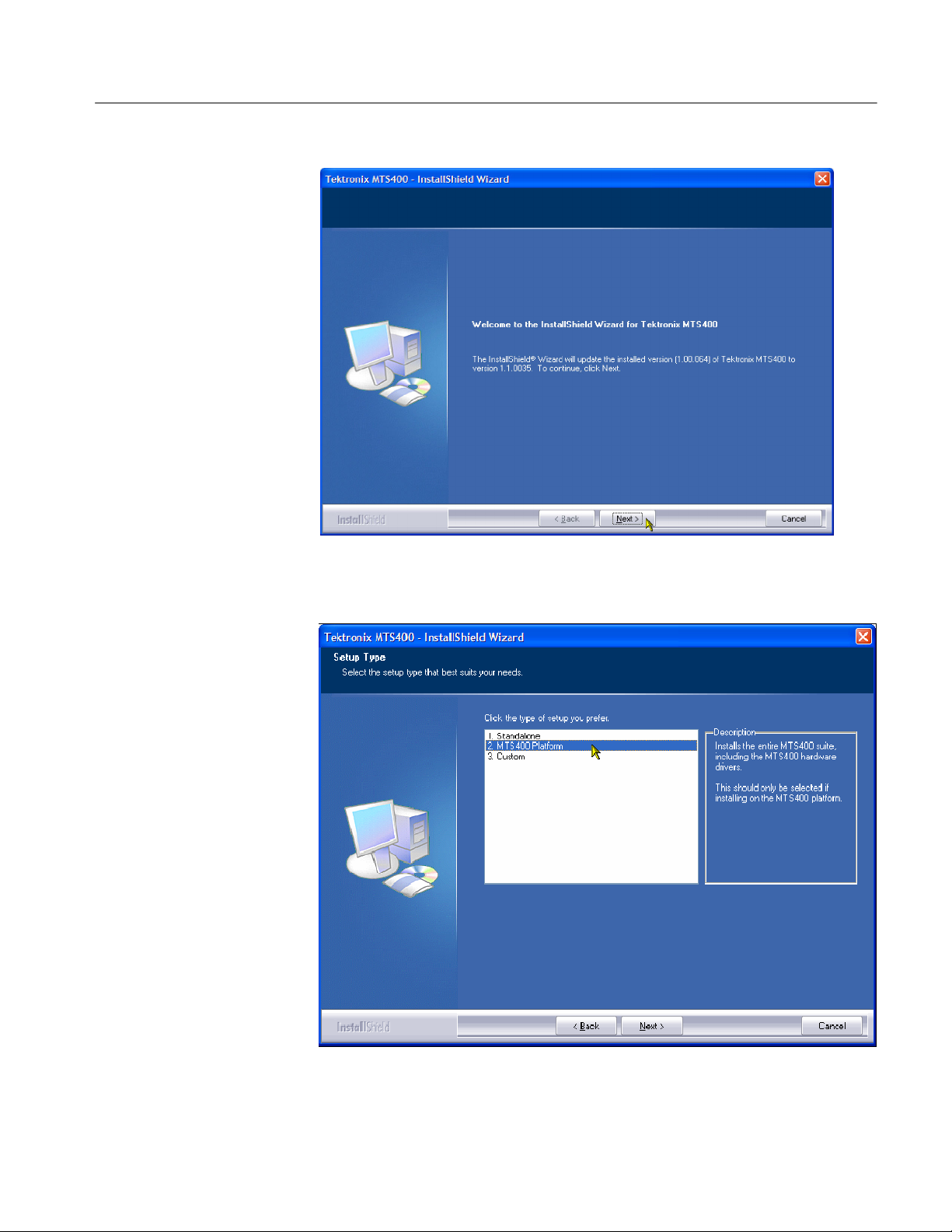
Upgrade Instructions
Figure 19: InstallShield Wizard welcome screen
Figure 20: MTS400 Installation - Setup Type
MTS4UP MTS400 Series Upgrade Kits
27
Page 36
Upgrade Instructions
5. Choose 2. MTS400 PLATFORM and select Next.
6. Allow the installation process to proceed. The average installation time is
approximately five minutes.
NOTE. A number of dialog boxes are displayed during the installation process.
Normally, no user intervention is required.
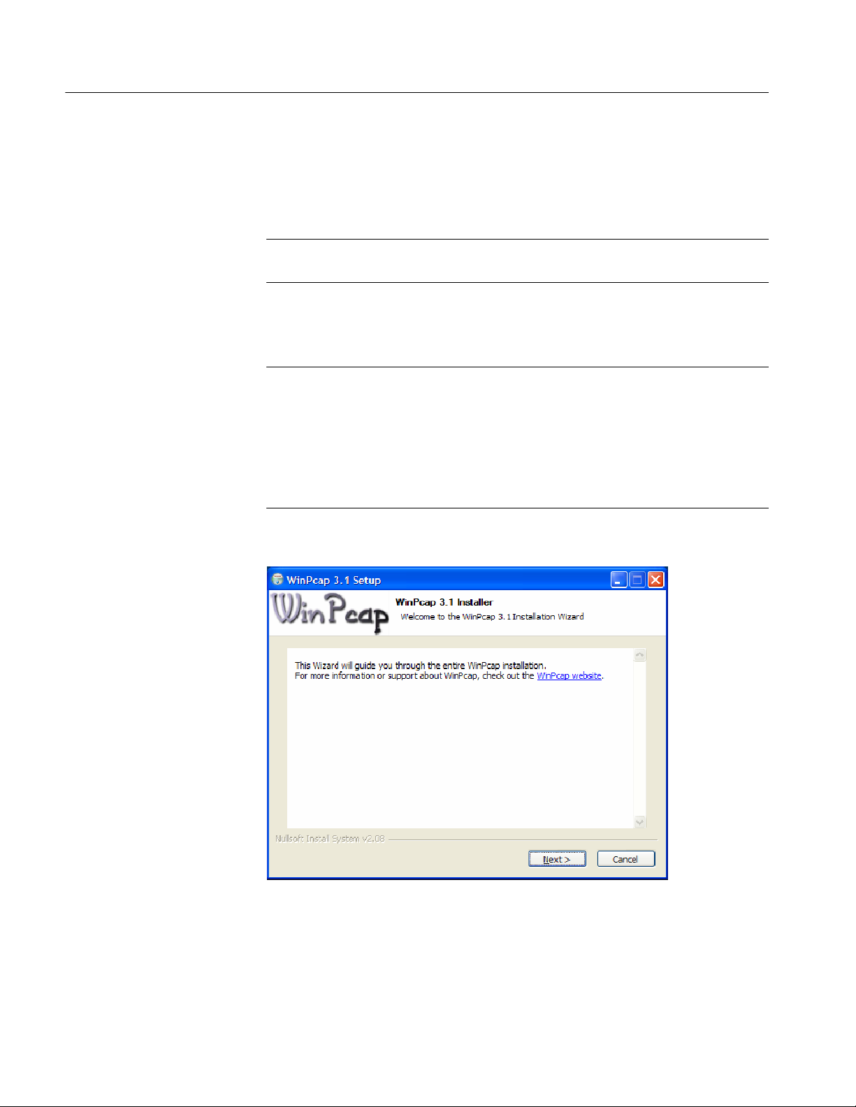
7. Allow the installation process to proceed until the WinPcap Setup dialog box
is displayed, See Figure 21.
NOTE. If WinPcap has been previously installed, the following message will be
displayed:
WinPcap 3.1 is already installed on this machine.
The installation will be aborted.
Select OK to abort the WinPcap installation and continue with the MTS400
installation.
28
Figure 21: WinPcap Setup dialog
8. In the WinPcap Setup dialog box, select Next.
MTS4UP MTS400 Series Upgrade Kits
Page 37

Upgrade Instructions
9. The WinPcap License agreement is displayed. Read the agreement and select
IAgreeif you agree.
10. When the WinPcap completed dialog appears, click FINISH.
11. When the upgrade installation is complete, the Update Complete screen is
displayed as shown in Figure 22.
Figure 22: InstallShield Wizard update complete screen
12. Select the Yes, I want to restart my computer now option, and then click
Finish. The instrument or PC will shut down and then restart.
13. After the unit has completed the start-up process, start the Tektronix Option
Update wizard by selecting Start > Programs > Tektronix MTS400 >
OptionKey Wizard. The Option Update window should open, as shown in
Figure 23.
MTS4UP MTS400 Series Upgrade Kits
29
Page 38
Upgrade Instructions
30
Figure 23: Tektronix Option Update Wizard - Initial view
Note that the Serial Number of the software key has been detected, but the
Key Status is invalid because no KeyString has been entered.
14. In the Tektronix Option Update dialog box Key String field, enter the Option
Key String, found on the Product Option Key label supplied with these
upgrade instructions, and then click Apply.
15. Inspect and verify the list of licensed options (see Figure 24).
MTS4UP MTS400 Series Upgrade Kits
Page 39

Upgrade Instructions
Figure 24: Tektronix Option Update Wizard - Complete
16. Close the Option Key Wizard.
17. Peel the backing off of the Product Option Key label and apply it to the
instrument rear panel, as shown in Figure 5. If there is already an option key
label on the rear panel, paste the new one over the old one.
The upgrade is now complete. The licensed MTS400applications will now be
available in the Windows Start menu.
MTS4UP MTS400 Series Upgrade Kits
31
Page 40

Upgrade Instructions
Verify Operation
For complete verification, perform the Performance Verification procedure found
in the Specifications and Performance Verification manual (071-1724-xx), on the
documentation CD included in this kit.
If any licensed application fails to open correctly, contact your Tektronix
representative.
Software Key Upgrade Instructions
Perform the following steps to upgrade the MTS400 software key. This process
can be used where a new application is to be licensed on an MTS400, software
version 1.4 or later, but the software does not require an upgrade.:
1. Ensure that the software key (dongle) is attached to your instrument.
Verify Operation
2. Switch the instrument on and allow the start-up process to complete.
3. Start the Tektronix Option Update Wizard (Start > Programs > Tektronix
MTS400 > OptionKey Wizard).
4. In the Tektronix Option Update Wizard dialog box, enter the Option Key
String, found on the Product Option Key label supplied with these upgrade
instructions, in the Key String field. Click Apply.
5. Inspect and verify the list of licensed options.
6. Close the Option Key Wizard.
7. Peel the backing off of the Product Option Key label and apply it to the
instrument rear panel, as shown in Figure 5. If there is already an option key
label on the rear panel, paste the new one over the old one.
The software key upgrade is now complete.
To verify operation of the upgraded applications, open and close each installed
application in turn.
32
If any licensed application fails to open correctly, contact your Tektronix
representative.
g End of document g
MTS4UP MTS400 Series Upgrade Kits
 Loading...