

Page 1

MTS400 Series
MPEG Test Systems
Getting Started Manual
071-1505-06
This document applies to version 1.4 and above.
Warning
The servicing instructions are for use by qualified
personnel only. To avoid personal injury, do not
perform any servicing unless you are qualified to
do so. Refer to all safety summaries prior to
performing service.
www.tektronix.com
Page 2

Copyright ©Tektronix. All rights reserved. Licensed software products are owned by Tektronix or its suppliers and
are protected by United States copyright laws and international treaty provisions.
Tektronix products are covered by U.S. and foreign patents, issued and pending. Information in this publication
supersedes that in all previously published material. Specifications and price change privileges reserved.
TEKTRONIX and TEK are registered trademarks of Tektronix, Inc.
Contacting Tektronix
Tektronix, Inc.
14200 SW Karl Braun Drive or P.O. Box 500
Beaverton, OR 97077 USA
For product information, sales, service, and technical support:
■ In North America, call 1-800-833-9200.
■ Worldwide, visit www.tektronix.com to find contacts in your area.
Page 3

Warranty 2
Tektronix warrants that this product will be free from defects in materials and workmanship for a period of one (1)
year from the date of shipment. If any such product proves defective during this warranty period, Tektronix, at its
option, either will repair the defective product without charge for parts and labor, or will provide a replacement in
exchange for the defective product. Parts, modules and replacement products used by Tektronix for warranty work
may be new or reconditioned to like new performance. All replaced parts, modules and products become the
property of Tektronix.
In order to obtain service under this warranty, Customer must notify Tektronix of the defect before the expiration of
the warranty period and make suitable arrangements for the performance of service. Customer shall be responsible
for packaging and shipping the defective product to the service center designated by Tektronix, with shipping
charges prepaid. Tektronix shall pay for the return of the product to Customer if the shipment is to a location within
the country in which the Tektronix service center is located. Customer shall be responsible for paying all shipping
charges, duties, taxes, and any other charges for products returned to any other locations.
This warranty shall not apply to any defect, failure or damage caused by improper use or improper or inadequate
maintenance and care. Tektronix shall not be obligated to furnish service under this warranty a) to repair damage
resulting from attempts by personnel other than Tektronix representatives to install, repair or service the product; b)
to repair damage resulting from improper use or connection to incompatible equipment; c) to repair any damage or
malfunction caused by the use of non-Tektronix supplies; or d) to service a product that has been modified or
integrated with other products when the effect of such modification or integration increases the time or difficulty of
servicing the product.
THIS WARRANTY IS GIVEN BY TEKTRONIX WITH RESPECT TO THE PRODUCT IN LIEU OF ANY
OTHER WARRANTIES, EXPRESS OR IMPLIED. TEKTRONIX AND ITS VENDORS DISCLAIM ANY
IMPLIED WARRANTIES OF MERCHANTABILITY OR FITNESS FOR A PARTICULAR PURPOSE.
TEKTRONIX' RESPONSIBILITY TO REPAIR OR REPLACE DEFECTIVE PRODUCTS IS THE SOLE AND
EXCLUSIVE REMEDY PROVIDED TO THE CUSTOMER FOR BREACH OF THIS WARRANTY.
TEKTRONIX AND ITS VENDORS WILL NOT BE LIABLE FOR ANY INDIRECT, SPECIAL, INCIDENTAL,
OR CONSEQUENTIAL DAMAGES IRRESPECTIVE OF WHETHER TEKTRONIX OR THE VENDOR HAS
ADVANCE NOTICE OF THE POSSIBILITY OF SUCH DAMAGES.
Page 4

Warranty 9(b)
Tektronix warrants that the media on which this software product is furnished and the encoding of the programs on
the media will be free from defects in materials and workmanship for a period of three (3) months from the date of
shipment. If any such medium or encoding proves defective during the warranty period, Tektronix will provide a
replacement in exchange for the defective medium. Except as to the media on which this software product is
furnished, this software product is provided "as is" without warranty of any kind, either express or implied.
Tektronix does not warrant that the functions contained in this software product will meet Customer's requirements
or that the operation of the programs will be uninterrupted or error-free.
In order to obtain service under this warranty, Customer must notify Tektronix of the defect before the expiration of
the warranty period. If Tektronix is unable to provide a replacement that is free from defects in materials and
workmanship within a reasonable time thereafter, Customer may terminate the license for this software product and
return this software product and any associated materials for credit or refund.
THIS WARRANTY IS GIVEN BY TEKTRONIX WITH RESPECT TO THE PRODUCT IN LIEU OF ANY
OTHER WARRANTIES, EXPRESS OR IMPLIED. TEKTRONIX AND ITS VENDORS DISCLAIM ANY
IMPLIED WARRANTIES OF MERCHANTABILITY OR FITNESS FOR A PARTICULAR PURPOSE.
TEKTRONIX' RESPONSIBILITY TO REPLACE DEFECTIVE MEDIA OR REFUND CUSTOMER'S
PAYMENT IS THE SOLE AND EXCLUSIVE REMEDY PROVIDED TO THE CUSTOMER FOR BREACH OF
THIS WARRANTY. TEKTRONIX AND ITS VENDORS WILL NOT BE LIABLE FOR ANY INDIRECT,
SPECIAL, INCIDENTAL, OR CONSEQUENTIAL DAMAGES IRRESPECTIVE OF WHETHER TEKTRONIX
OR THE VENDOR HAS ADVANCE NOTICE OF THE POSSIBILITY OF SUCH DAMAGES.
Page 5

Table of Contents
General Safety Summary ...................................................................................... v
Service Safety Summary...................................................................................... vii
Environmental Considerations ............................................................................ ix
Preface.................................................................................................................... xi
Related Material..................................................................................................... xii
Manual Conventions........................................................................................... xiii
Getting Started
Product Description ............................................................................................ 1-1
Features and Benefits............................................................................................ 1-2
Hardware Features ................................................................................................ 1-3
Options.................................................................................................................. 1-4
Accessories ......................................................................................................... 1-12
Software Protection............................................................................................. 1-13
MTS400 Series system Installation.................................................................. 1-15
Unpacking the MTS400 Series system ............................................................... 1-15
Standard Test System Interconnections .............................................................. 1-15
Powering On and Off .......................................................................................... 1-22
Network Installation............................................................................................ 1-23
Duplex Operation................................................................................................ 1-23
MTS4SA Stand-Alone System Installation..................................................... 1-27
Installation........................................................................................................... 1-29
VLC Media Player Installation ........................................................................... 1-37
Starting an Application ....................................................................................1-39
Starting the TSCA............................................................................................... 1-40
Setting the Interpretation Standard ..................................................................... 1-42
Off-Line Analysis ...............................................................................................1-44
Real-Time Analysis ............................................................................................ 1-46
Stream Analysis Results...................................................................................... 1-47
Operating Basics
Operating Basics .................................................................................................2-1
Software Applications........................................................................................... 2-1
MTS400 Series MPEG Test Systems Getting Started Manual i
Page 6

Table of Contents
Appendices
Appendix A: Cleaning and Maintenance ......................................................... A-1
General Care......................................................................................................... A-1
Preventive Maintenance .......................................................................................A-1
In Case of Problems ............................................................................................. A-3
Repackaging for Shipment................................................................................... A-4
Appendix B: MTS400 Series system Recovery................................................ B-1
Overview .............................................................................................................. B-1
Restore Operating System.................................................................................... B-3
Install the MTS400 Series system Applications................................................... B-8
Reformat the SCSI Drives.................................................................................... B-9
Appendix C: Network Troubleshooting........................................................... C-1
Basic Requirements.............................................................................................. C-1
IP Parameters ....................................................................................................... C-2
Common Troubleshooting Procedures................................................................. C-5
Sources of Network Information.......................................................................... C-8
Glossary
Index
ii MTS400 Series MPEG Test Systems Getting Started Manual
Page 7

Table of Contents
List of Figures
Figure 1-1: MTS400 Series system front panel..................................................................1-1
Figure 1-2: MTS400 Series system rear-panel connectors...............................................1-16
Figure 1-3: SFP module ................................................................................................... 1-20
Figure 1-4: TSCA - File Open..........................................................................................1-47
Figure B-1: SCSI drives automatically recognized........................................................... B-4
Figure B-2: Computer Management - SCSI drives, foreign.............................................. B-5
Figure B-3: Select Import Foreign Disks… ...................................................................... B-5
Figure B-4: Import Foreign Disks dialog box................................................................... B-6
Figure B-5: Foreign Disk Volumes dialog box ................................................................. B-6
Figure B-6: SCSI drives manually recognized.................................................................. B-7
Figure B-7: MTS400 Installation – Setup Type................................................................ B-8
Figure C-1: Incorrect IP address ....................................................................................... C-2
Figure C-2: Incorrect subnet mask.................................................................................... C-3
Figure C-3: Incorrect default gateway IP address............................................................. C-4
Figure C-4: Ping.exe command window........................................................................... C-6
Figure C-5: Tracert.exe command window....................................................................... C-7
Figure C-6: Command prompt with nslookup results....................................................... C-8
MTS400 Series MPEG Test Systems Getting Started Manual iii
Page 8

Table of Contents
List of Tables
Table 1-1: MTS400 System options .................................................................................1-4
Table 1-2: MTS430 System options .................................................................................1-7
Table 1-3: MTS4SA Stand-alone System options .............................................................1-9
Table 1-4: MTS4UP options ........................................................................................... 1-10
Table 1-5: Standard accessories for the MTS400 Series system ..................................... 1-12
Table 1-6: Standard accessories for the MTS4SA Stand-Alone System .........................1-13
Table 1-7: Rear-panel connectors .................................................................................... 1-17
Table 1-8: Electrical operating requirements................................................................... 1-21
Table 1-9: MTS400 Series system Start menu................................................................. 1-39
Table 2-1: MTS400 / MTS430 / MTS4SA / MTS4UP installed applications .................. 2-1
Table A-1: Troubleshooting power-on failures................................................................. A-3
Table B-1: MTS400 Series system Recovery Media........................................................ B-1
iv MTS400 Series MPEG Test Systems Getting Started Manual
Page 9

General Safety Summary
Review the following safety precautions to avoid injury and prevent damage to this
product or any products connected to it.
To avoid potential hazards, use this product only as specified.
Only qualified personnel should perform service procedures.
While using this product, you may need to access other parts of the system. Read
the General Safety Summary in other system manuals for warnings and cautions
related to operating the system.
To Avoid Fire or Personal Injury
Use Proper Power Cord. Use only the power cord specified for this product and
certified for the country of use.
Connect and Disconnect Properly. Do not connect or disconnect probes or test
leads while they are connected to a voltage source.
Ground the Product. This product is grounded through the grounding conductor of
the mainframe power cord. To avoid electric shock, the grounding conductor must
be connected to earth ground. Before making connections to the input or output
terminals of the product, ensure that the product is properly grounded.
Observe All Terminal Ratings. To avoid fire or shock hazard, observe all ratings
and markings on the product. Consult the manual for further ratings information
before making connections to the product.
Do not apply a potential to any terminal, including the common terminal, that
exceeds the maximum rating of that terminal
Powering Off. The power cord provides Mains disconnect.
Replace Batteries Properly. Replace batteries with the same type and rating.
Do Not Operate Without Covers. Do not operate this product with covers or panels
removed.
Use Proper Fuse. Use only the fuse type and rating specified for this product.
Avoid Exposed Circuitry. Do not touch exposed connections and components when
power is present.
MTS400 Series MPEG Test Systems Getting Started Manual v
Page 10
General Safety Summary
Wear Eye Protection. Wear eye protection if exposure to high-intensity rays or
laser radiation exists.
Do Not Operate With Suspected Failures. If you suspect there is damage to this
product, have it inspected by qualified service personnel.
Do Not Operate in Wet/Damp Conditions.
Do Not Operate in an Explosive Atmosphere.
Keep Product Surfaces Clean and Dry.
Provide Proper Ventilation. Refer to the manual’s installation instructions for
details on installing the product so it has proper ventilation.
Symbols and Terms
Terms in this Manual. These terms may appear in this manual:
WARNING. Warning statements identify conditions or practices that could result in
injury or loss of life.
CAUTION. Caution statements identify conditions or practices that could result in
damage to this product or other property.
Terms on the Product. These terms may appear on the product:
DANGER indicates an injury hazard immediately accessible as you read the
marking.
WARNING indicates an injury hazard not immediately accessible as you read the
marking.
CAUTION indicates a hazard to property including the product.
Symbols on the Product. The following symbols may appear on the product:
CAUTION
Refer to Manual
WARNING
High Voltage
Protective Ground
(Earth) Terminal
Standby
vi MTS400 Series MPEG Test Systems Getting Started Manual
Page 11

Service Safety Summary
Only qualified personnel should perform service procedures. Read this Service
Safety Summary and the General Safety Summary before performing any service
procedures.
Do Not Service Alone. Do not perform internal service or adjustments of this
product unless another person capable of rendering first aid and resuscitation is
present.
Disconnect Power. To avoid electric shock, switch off the instrument power, then
disconnect the power cord from the mains power.
Use Care When Servicing With Power On. Dangerous voltages or currents may
exist in this product. Disconnect power, remove battery (if applicable), and
disconnect test leads before removing protective panels, soldering, or replacing
components.
To avoid electric shock, do not touch exposed connections.
MTS400 Series MPEG Test Systems Getting Started Manual vii
Page 12

Service Safety Summary
viii MTS400 Series MPEG Test Systems Getting Started Manual
Page 13

Environmental Considerations
This section provides information about the environmental impact of the product.
Product End-of-Life Handling
Observe the following guidelines when recycling an instrument or component:
Equipment Recycling. Production of this equipment required the extraction and use
of natural resources. The equipment may contain substances that could be harmful
to the environment or human health if improperly handled at the product's end of
life. In order to avoid release of such substances into the environment and to
reduce the use of natural resources, we encourage you to recycle this product in an
appropriate system that will ensure that most of the materials are reused or
recycled appropriately.
The symbol shown to the left indicates that this product complies with
the European Union's requirements according to Directive 2002/96/EC
on waste electrical and electronic equipment (WEEE). For information
about recycling options, check the Support/Service section of the
Tektronix Web site (www.tektronix.com).
Mercury Notification. This product uses an LCD backlight lamp that contains
mercury. Disposal may be regulated due to environmental considerations. Please
contact your local authorities or, within the United States, the Electronics
Industries Alliance (www.eiae.org) for disposal or recycling information.
Restriction of Hazardous Substances
This product has been classified as Monitoring and Control equipment, and is
outside the scope of the 2002/95/EC RoHS Directive.
MTS400 Series MPEG Test Systems Getting Started Manual ix
Page 14

Environmental Considerations
x MTS400 Series MPEG Test Systems Getting Started Manual
Page 15

Preface
This manual describes the functions and use of the Tektronix MTS400 Series
MPEG Test Systems. The following naming conventions are used in this manual:
MTS400 Series system – for information that applies to the MTS400, the
MTS430, and the MTS4SA
MTS400 system – for information that applies to only the MTS400
MTS430 system - for information that applies to only the MTS430
MTS4SA Stand-alone system - for information that applies to only the
MTS4SA
MTX100B/RTX100B/RTX130B - for information that applies to only the
MTX100B MPEG Recorder and Player, the RTX100B ISDB-T RF Signal
Generator, and the RTX130B QAM and VSB RF Signal Generator.
The manual is organized into the following sections:
Getting Started
Description and overview of the MTS400 Series system, plus instructions for
installing the stand-alone version of the MTS400 Series system.
Operating Basics
A brief introduction to the software applications installed in the MTS400
Series system. For detailed operating information about the applications, refer
to the MTS400 Series MPEG Test Systems User Manual.
Appendices
Appendix A: Cleaning and Maintenance.
Appendix B: System Recovery. Explains how to reinstall the operating
system and application software if you encounter problems with the
software.
Appendix C: Network Troubleshooting. A high-level overview of
diagnosing and troubleshooting network connection problems.
Glossary
Index
MTS400 Series MPEG Test Systems Getting Started Manual xi
Page 16

Preface
Related Material
The following table lists the other manuals available for the MTS400 Series
system.
Related documentation
Title Part number Description
MTS400 Series
MPEG Test Systems
User Manual
MTS400 Series
MPEG Test Systems
Technical Reference
MTS400 Series
MPEG Test Systems
Programmers Manual
MTS400 Series
MPEG Test Systems
Release Notes
MTS400 Series
MPEG Test Systems
Getting Started
Manual (Japanese)
MTS4EA Compressed
Video Elementary
Stream Analyzer User
Manual
071-1507-xx Provides in-depth operating information for the
software applications included in the MTS400
Series system.
071-1724-xx Provides the MTS400 Series system
specifications and a performance verification
procedure. Available only as a PDF file on the
MTS400 Series Customer Documentation
CD-ROM.
071-1725-xx Provides the remote control commands for the
Player application. Available only as a PDF file
on the MTS400 Series Customer
Documentation CD-ROM.
071-1726-xx Provides information about software problems
and behaviors.
071-1727-xx Provides a Japanese language version of this
manual.
071-1641-xx Provides operating information for the optional
MTS4EA Compressed Video ES Analyzer
application.
Additional documentation, such as Read Me files, may be included on the
installation disks.
User documents can also be downloaded from the Tektronix Web site:
www.tektronix.com/manuals.
xii MTS400 Series MPEG Test Systems Getting Started Manual
Page 17

Preface
The following URLs access the Web sites for the standards organizations listed
(the URLs listed were valid at the time of writing):
MPEG-2 standards (International Organization for Standards)
www.iso.org/
DVB standards (European Technical Standards Institute)
www.etsi.org/
ATSC standards (Advanced Television Systems Committee)
www.atsc.org/
Manual Conventions
Naming conventions for the interface elements are based on standard Windows
naming conventions.
Naming conventions for MPEG-2, ATSC, and DVB structures follow the
conventions established by the standards organizations.
The following formatting conventions apply to this manual:
Bold text refers to specific interface elements that you are instructed to select,
click, or clear.
Example: Select Settings from the Configuration menu.
Mono-spaced text can indicate the following:
Text you enter from a keyboard
Example: Enter the network identity (http://TSMonitor01)
Characters you push on your keyboard
Example: Push
CTRL+C to copy the selected text.
Paths to components on your hard drive
Example: The program files are installed at the following location:
C:\Program Files\Tektronix\
MTS400 Series MPEG Test Systems Getting Started Manual xiii
Page 18

Preface
xiv MTS400 Series MPEG Test Systems Getting Started Manual
Page 19

Getting Started
Page 20

Page 21
Product Description
The MTS400 Series MPEG Test Systems provide a comprehensive and integrated
suite of real-time and deferred (offline) analysis tools. The tools include TS
(transport stream) compliance, buffer, PES, MPEG2, and MPEG4 video and audio
elementary stream analyzers. Also included are an editor and a multiplexer to
create stream content, and test and error-stressing streams.
Standards compliance is ensured though built-in customizable scripting, which
supports a broad range of ratified and evolving DTV standards. New standards and
proprietary tables can easily be implemented by loading Tektronix supplied
updates, or creating your own custom scripts.
The MTS400 series instruments have a large LCD display with a powerful
2.8 GHz processor with support for multiple physical layer interfaces such as ASI,
SPI, SMPTE310M, RF, including QAM (annex B), COFDM DVB-T,
QPSK/8PSK, and 8VSB, and IP (10/100 BaseT and Gigabit Ethernet).
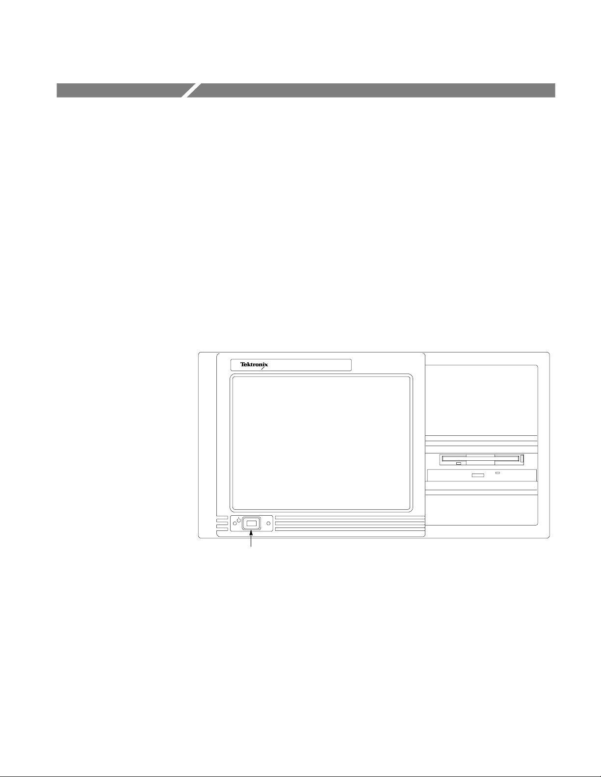
On/Stby switch
Figure 1-1: MTS400 Series system front panel
There are three variants of the MTS400 Series MPEG Test System: the MTS400
system, the MTS430 system, and the MTS4SA Stand-alone system.
The MTS400 system includes SPI, ASI and SMPTE310M interfaces, real-
time transport stream analysis and transport stream play and record.
MTS400 Series MPEG Test Systems Getting Started Manual 1-1
Page 22

Product Description
Features and Benefits
The MTS430 system includes SPI, ASI and SMPTE310M and 10/100 IP
interfaces, real-time transport stream analysis, play and record, deferred time
transport stream, packetized elementary stream, and buffer analysis and
multiplexing.
The MTS4SA Stand-alone system allows the deferred analysis and testing
components to be installed on a personal computer.
See Options, starting on page 1-4, for the details of each system.
The MTS400 Series software will also run on the MTX100B, RTX100B, and
RTX130B. Real-time analysis requires that the MTX100B Option 7 is available.
The system provides the following features:
The CaptureVu™ feature captures and analyzes system events in real time
and deferred time to debug the intermittent and complex problems that
traditional analyzers miss.
Real-time video over IP analysis and recording for broadband and video on
demand applications is supported using the MTS430 system’s built-in Gigabit
Ethernet port. (This feature is also available separately as a stand-alone
application to run on your PC with a standard 10/100 or Gigabit Ethernet
network interface card).
High performance analysis engine to analyze transport streams up to
400 Mbps (in deferred time). This greatly reduces the amount of time taken
by the deferred time software to analyze large and complex transport stream
files. This capability also protects your investment in the MTS400 because the
deployment of new services, such as VOD and HD, will require greater
aggregated bandwidth and data rates than are available in other products
today.
The innovative “program centric” user interface brings expert power to the
novice user by helping locate network and service related problems fast.
Broadest and deepest range of analysis of legacy and next generation
compressed standards including MPEG-2, MPEG-4, H.264,
and SMPTE VC-1. Mobile video standards included are 3GPP and DVB-H.
Support for a full and wide range of current world-wide DTV standards.
Rapid implementation and analysis of new and proprietary DTV standards is
enabled by a flexible user-definable scripting language.
Modular design allows you to purchase only the performance that you require
today and makes it easy to upgrade for changing needs.
1-2 MTS400 Series MPEG Test Systems Getting Started Manual
Page 23

Product Description
Hardware Features
The basic MTS400 Series instrument consists of:
One, 80 GB IDE hard drive
(disk space, operating system and software applications)
Two, 72 GB SCSI hard drives (disk space, MPEG file storage)
2.8 GHz P4 processor
1 GB RAM
DVD drive (-R/-RW,+R/+RW)
3.5 inch floppy disk drive (1.44 MB high-density)
An LCD display, 1024 x 768, 10.4 inch
Operating System: Windows XP Pro
Ethernet connectors
(one 10/100-base T connector and one 10/100/1000-base T connector)
USB port
A170 card, LVDS/ASI/SMPTE310 interface
A12 card, main MPEG input/output
MTS400 Series MPEG Test Systems Getting Started Manual 1-3
Page 24

Product Description
Options
MTS400 System Options
A range of options is available for the MTS400 Series MPEG Test Systems. The
option descriptions begin on the following pages:
MTS400 System Options (page 1-4)
MTS430 System Options (page 1-7)
MTS4SA Stand-alone System (page 1-9)
MTS4UP Options (page 1-10)
The MTS400 platform includes SPI, ASI, SMPTE310M interfaces, real time TS
analysis, and TS play and record.
MTS400 System Basic Application Set.
Transport Stream Compliance Analyzer (TSCA) - Real Time
Tracer
Player / Recorder
TS Editor
TS Cutter
Script Pad
Table 1-1: MTS400 System options (cont.)
Item Opt Description
MTS400
MTS400 Series MPEG Test System
IPE Add 10/100BaseT Video over IP electrical interface to MTS400
MX Add Deferred Time Multiplexer to MTS400
ES Add ES Analyzer to MTS400
BA Add Buffer Analyzer to MTS400
PA Add PES to MTS400
DB Add Carousel Analyzer to MTS400
CG Add Carousel Generator to MTS400
DBCG Add Carousel Analyzer and Carousel Generator to MTS400
1-4 MTS400 Series MPEG Test Systems Getting Started Manual
Page 25

Product Description
Table 1-1: MTS400 System options (cont.)
Item Opt Description
MTS400
L99 Electronic User Documentation (No printed manuals)
TSCA Add Transport Stream Compliance Analyzer to MTS400
TSCL Add Transport Stream Compliance Analyzer Lite (file size limited) to
MTS400
GBE Add GbE (GigE) Video over IP interface to MTS400, includes IP analysis
software
CU 1000BASE-T electrical port with RJ45 connector for MTS400 gigabit
Ethernet interface
LX 1000BASE-LX long wavelength optical port with LC connector for
MTS400 gigabit Ethernet interface (single mode 1310 NM)
SX 1000BASE-SX short wavelength optical port with LC connector for
MTS400 gigabit Ethernet interface (multi mode 850 NM)
ZX 1000BASE-ZX long wavelength optical port with LC connector for
MTS400 gigabit Ethernet interface (single mode 1550 NM)
CF Add COFDM DVB-T interface to MTS400
EP Add QPSK/8PSK interface to MTS400
QB2 Add QAM (Annex B) interface to MTS400
VS Add 8VSB interface to MTS400
R3 Repair Service 3 years
R5 Repair service 5 years
L0 English Documentation
L5 Japanese Documentation
A0 North American Power
A1 Universal Euro Power
A2 United Kingdom Power
A3 Australia Power
A4 240 V North America Power
A5 Switzerland Power
A6 Japan Power
A10 China Power
A11 India Power
A99 No Power cord or AC adapter
Additional MTS4EA Options (Compressed Video ES Analyzer) (at order time)
MTS400
4EAB Base software with video standard package including: MPEG-4 Simple
Profile, H.263+, H.263, H.261, CD and Manual
M4SP MPEG-4 Advanced Simple Profile (Levels 0 - 5)
M2ML MPEG-2 Main Profile Main Level
MTS400 Series MPEG Test Systems Getting Started Manual 1-5
Page 26

Product Description
Table 1-1: MTS400 System options (cont.)
Item Opt Description
M2HL MPEG-2 Main Profile High Level & High Level 1440 (High Definition)
AVCE H.264/AVC Baseline and Extended Profiles (Levels 1 - 5)
AVCH H.264/AVC High Profile with FREXT (10 bit, 4:22:2, 4:4:4)
AVCM H.264/AVC Main Profile (Levels 1 - 5)
AVDM Audio visual delay measurement. Requires option 4EAB
SWSE First 12 Months’ Software Subscription on the MTS4EA software and its
options loaded on the MTS400, when purchased with a new MTS400.
(Does not cover the MTS400 software.)
VC-1 VC-1 (all profiles, all levels) and Windows Media V9 (ASF)
AUD Audio (including AAC, HE AAC, AC-3)
1-6 MTS400 Series MPEG Test Systems Getting Started Manual
Page 27

Product Description
MTS430 System Options
The MTS430 platform includes SPI, ASI, SMPTE310M and 10/100 IP interfaces,
real time TS analysis, play and record, deferred time TS, PES and Buffer Analysis,
and Multiplexing.
MTS430 System Basic Application Set.
Transport Stream Compliance Analyzer (TSCA) - Real Time / Deferred
Packetized Elementary Stream (PES) Analyzer
Transport Stream – System Target Decoder (T-STD) Buffer Analyzer
Tracer
Player / Recorder
TS Editor
Multiplexer (+ Make Seamless Wizard)
TS Cutter
Script Pad
Table 1-2: MTS430 System options (cont.)
Item Opt Description
MTS430
MTS430 MPEG Test System
ES Add ES Analyzer to MTS430
DB Add Carousel Analyzer to MTS430
CG Add Carousel Generator to MTS430
DBCG Add Carousel Analyzer and Carousel Generator to MTS430
GBE Add GbE (GigE) Video over IP interface to MTS400, includes IP analysis
software
CU 1000BASE-T electrical port with RJ45 connector for MTS400 gigabit
Ethernet interface
LX 1000BASE-LX long wavelength optical port with LC connector for
MTS400 gigabit Ethernet interface (single mode 1310 NM)
SX 1000BASE-SX short wavelength optical port with LC connector for
MTS400 gigabit Ethernet interface (multi mode 850 NM)
ZX 1000BASE-ZX long wavelength optical port with LC connector for
MTS400 gigabit Ethernet interface (single mode 1550 NM)
SWSM First 12 months MTS400 software subscription (Does not include
subscription to MTS4EA)
MTS400 Series MPEG Test Systems Getting Started Manual 1-7
Page 28

Product Description
Table 1-2: MTS430 System options (cont.)
Item Opt Description
MTS430
A11 India Power
A99 No Power cord or AC adapter
CF Add COFDM DVB-T interface to MTS430
EP Add QPSK/8PSK interface to MTS430
QB2 Add QAM (Annex B) interface to MTS430
VS Add 8VSB interface to MTS430
R3 Repair Service 3 years
R5 Repair service 5 years
L0 English Documentation
L5 Japanese Documentation
L99 Electronic User Documentation (No printed manuals)
A0 North American Power
A1 Universal Euro Power
A2 United Kingdom Power
A3 Australia Power
A4 240V North America Power
A5 Switzerland Power
A6 Japan Power
A10 China Power
Additional MTS4EA Options (Compressed Video ES Analyzer) (at order time)
MTS430
4EAB Base software with video standard package including: MPEG-4 Simple
Profile, H.263+, H.263, H.261, CD and Manual
M4SP MPEG-4 Advanced Simple Profile (Levels 0 – 5)
M2ML MPEG-2 Main Profile Main Level
M2HL MPEG-2 Main Profile High Level & High Level 1440 (High Definition)
AVCE H.264/AVC Baseline and Extended Profiles (Levels 1 – 5)
AVCM H.264/AVC Main Profile (Levels 1 – 5)
SWSE First 12 Months Software Subscription on the MTS4EA software and its
options loaded on the MTS430, when purchased with a new MTS430.
(Does not cover the MTS430 software.)
VC-1 VC-1 (all profiles, all levels) and Windows Media V9 (ASF)
AUD Audio (including AAC, HE AAC, AC-3)
1-8 MTS400 Series MPEG Test Systems Getting Started Manual
Page 29

Product Description
MTS4SA Stand-alone System
This product provides deferred analysis software for stand-alone operation.
MTS4SA Stand-alone System Basic Application Set
Tracer
Player
TS Editor
TS Cutter
Script Pad
Table 1-3: MTS4SA Stand-alone System options
Item Opt Description
MTS4SA
Stand Alone Deferred Time Software Package
USB USB Security software key supplied with Stand
Alone Software Package
PPD Parallel Port Security software supplied with Stand
Alone Software Package
MX Security software key to add Deferred Time Multiplexer to MTS4SA
ES Security software key to add ES Analyzer to MTS4SA
PB Security software key to add PES & Buffer Analyzer to MTS4SA
BA Security software key to add Buffer Analyzer to MTS4SA
PA Security software key to add PES to MTS4SA
DB Security software key to add Carousel Analyzer to MTS4SA
CG Security software key to add Carousel Generator to MTS4SA
DBCG Security software key to add Carousel Analyzer and Carousel Generator
to MTS4SA
TSCA Security software key to add Deferred Time Transport Stream
Compliance Analyzer to MTS4SA
TSCB Security software key to add real time and deferred time Transport
Stream Compliance Analyzer to MTS4SA for IP interface only
TSCL Security software key to add Deferred Time Transport Stream
Compliance Analyzer Lite (file size limited) to MTS4SA
TSCR Security software key to add Real Time Transport Stream Compliance
Analyzer to MTS4SA for IP interface only
L0 English Documentation
L5 Japanese Documentation
L99 Electronic User Documentation (No printed manuals)
Upgrade
requires either
USB or PPD
(not both).
MTS400 Series MPEG Test Systems Getting Started Manual 1-9
Page 30

Product Description
MTS4UP Options
The MTS4UP options allow you to upgrade to add options after ordering an
MTS400, MTS430, or MTS4SA.
Table 1-4: MTS4UP options (cont.)
Item Opt Description
MTS4UP
MTS4 Series Field Upgrade Kit
IPE Add 10/100BaseT Video over IP electrical interface to MTS400
MX Add Deferred Time Multiplexer to MTS4 series
ES Add ES Analyzer to MTS4 series
BA Add Buffer Analyzer to MTS4 series
PA Add PES to MTS4 series
DB Add Carousel Analyzer to MTS4 series
CG Add Carousel Generator to MTS4 series
DBCG Add Carousel Analyzer and Carousel Generator to MTS4 series
TSCA Add Transport Stream Compliance Analyzer to MTS4 series
TSCB Upgrade to add real time and deferred time transport stream
compliance analyzer to MTS4SA for IP interface only
TSCL Add Transport Stream Compliance Analyzer Lite (file size limited) to
MTS4 series
TSCP Upgrade to add Transport Stream Compliance Analyzer, PES Analyzer
and Buffer Analyzer to MTS4 series
TSCR Add Real Time Transport Stream Compliance Analyzer to MTS4SA for
IP interface only
UPG Upgrade to latest version of MTS4 series base software and installed
options. Includes CD and Manual (excluding MTS4EA). Requires
MTS4UP Opt. SWS1.
IF Tektronix installs MTS4UP
IFC Tektronix installs MTS4UP with calibration
GBE Add GbE (GigE) Video over IP interface to MTS400, includes IP analysis
software
CU 1000BASE-T electrical port with RJ45 connector for MTS400 gigabit
Ethernet interface
LX 1000BASE-LX long wavelength optical port with LC connector for
MTS400 gigabit Ethernet interface (single mode 1310 NM)
SX 1000BASE-SX short wavelength optical port with LC connector for
MTS400 gigabit Ethernet interface (multi mode 850 NM)
ZX 1000BASE-ZX long wavelength optical port with LC connector for
MTS400 gigabit Ethernet interface (single mode 1550 NM)
CF Add COFDM DVB-T interface to MTS400
1-10 MTS400 Series MPEG Test Systems Getting Started Manual
Page 31

Product Description
Table 1-4: MTS4UP options (cont.)
Item Opt Description
MTS4UP
EP Add QPSK/8PSK interface to MTS400
QB2 Add QAM (Annex B) interface to MTS400
VS Add 8VSB interface to MTS400
L0 English documentation
L5 Japanese documentation
L99 Electronic user documentation (no printed manuals)
Accessories
Table 1-5 lists the standard accessories that are shipped with the MTS400 Series
system.
Table 1-5: Standard accessories for the MTS400 Series system (cont.)
Quantity Description Part number
1 each Compliance certificate 001-1180-xx
1 each Easy Restore License NA
1 each Certificate Of Authenticity: Microsoft Windows XP NA
1 each Software package: Operating System Restore DVD,
MTS400 MPEG Test System
1 each Software package: MTS400 MPEG Test System Installation
CD-ROM
1 each Software package: MTS400 MPEG Test System product
documentation CD-ROM
1 each Keyboard, 105 key layout 119-6989-xx
2 each Cable assembly; RF, BNC to BNC; 75 Ω 174-4954-xx
2 each Cable assembly: DB25 174-4955-xx
1 each Opt. L0 only: Getting Started manual (English) 071-1505-xx
1 each Opt. L5 only: Getting Started manual (Japanese) 071-1727-xx
1 each Opt. L99 only: Product Documentation CD-ROM 063-3857-xx
1 each Release notes 071-1726-xx
1 each Software key, parallel port 119-6962-xx
COFDM RF Interface only
1 each Adapter, RF; BNC to F type 015-0688-xx
1 each Cable assembly; RF, BNC to BNC; 75 Ω 174-5135-xx
063-3971-xx
063-3814-xx
063-3857-xx
MTS400 Series MPEG Test Systems Getting Started Manual 1-11
Page 32

Product Description
Table 1-5: Standard accessories for the MTS400 Series system (cont.)
Quantity Description Part number
QPSK/8PSK RF Interface only
1 each Cable assembly; RF, BNC to BNC; 75 Ω 174-5135-xx
QAM B RF Interface only
1 each Cable assembly; RF, BNC to BNC; 75 Ω 174-5135-xx
8VSB RF Interface only
1 each Adapter, RF; BNC to F type 015-0668-xx
1 each Cable assembly; RF, BNC to BNC; 75 Ω 174-5135-xx
Table 1-6 lists the standard accessories that are shipped with the MTS4SA Standalone System.
Table 1-6: Standard accessories for the MTS4SA Stand-Alone System
Quantity Description Part number
1 each Compliance certificate 001-1180-01
1 each Software package: CD-ROM, MTS400 MPEG Test System 063-3814-xx
1 each Software package: MTS400 MPEG Test System product
documentation CD-ROM
1 each Opt. PPD only: Software key (dongle); Parallel or USB port NA
1 each Opt. L0 only: Getting Started manual (English) 071-1505-xx
1 each Opt. L5 only: Getting Started manual (Japanese) 071-1727-xx
1 each Opt. L99 only: Product Documentation CD-ROM 063-3857-xx
1 each Release notes 071-1726-xx
1 each Software key, parallel port 119-6962-xx
063-3857-xx
1-12 MTS400 Series MPEG Test Systems Getting Started Manual
Page 33

Product Description
Software Protection
Purchased MTS400 Series system software options are enabled by the application
of an option key string in association with a software key containing a unique
serial number. A software key is a small hardware device. Two types of key are
available; one can be connected to the parallel port, and the other can be connected
to the USB (Universal Serial Bus) port. The type of software key that is supplied
with your product will depend on which product configuration you ordered. For
the MTS400 Series system and the MTX100B/RTX100B/RTX130B, the parallel
port software key is initially installed at the factory.
If you subsequently obtain additional options, software (and upgrade instructions)
will be supplied.
Any printer that is compatible with the installed operating system can be connected
to the unit through the parallel port version of the software key.
MTS400 Series MPEG Test Systems Getting Started Manual 1-13
Page 34

Product Description
1-14 MTS400 Series MPEG Test Systems Getting Started Manual
Page 35

MTS400 Series System Installation
This section describes how to install the MTS400 Series system instruments. The
analysis functions (if enabled) can be used with no installation other than providing
power and making a transport stream available on the hard disk of the unit. The
monitoring and real-time analysis functions similarly require power, but also
require connection to an external transport stream.
The MTS400 Series system and the MTX100B/RTX100B/RTX130B are
configured with the software and hardware options that you ordered at the time of
purchase. MTS400 Series system options can be added using upgrade kits
available from Tektronix.
Unpacking the MTS400 Series System
Table 1-5 on page 1-11 lists the standard accessories that are shipped with the
MTS400 Series system.
Instrument Operating Position
CAUTION. Do not operate the MTS400 Series system instrument in the vertical
position. Using it in the vertical position does not allow sufficient ventilation or
clearance for cables at the rear of the unit.
Standard Test System Interconnections
Use the following procedure to make electrical, signal, and network connections:
CAUTION. Do not supply power to the instrument until all other connections have
been made.
MTS400 Series MPEG Test Systems Getting Started Manual 1-15
Page 36

MTS400 Series System Installation
Figure 1-2 and Table 1-7 show the MTS400 Series system rear-panel connectors.
When the instrument is mounted securely, make the transport stream, network and
peripheral device connections necessary for the working environment.
Figure 1-2: MTS400 Series system rear-panel connectors
CAUTION. To prevent instrument damage from overheating, maintain at least two
inches (5.1 cm) of clearance at the rear and sides of the instrument cabinet when
locating the instrument on a bench.
1-16 MTS400 Series MPEG Test Systems Getting Started Manual
Page 37

MTS400 Series System Installation
The following table describes the transport stream, network and peripheral device
connectors. See the MTS400 Series MPEG Test Systems Technical Reference for
more detailed information about each connector and signal input and output
formats.
Table 1-7: Rear-panel connectors (cont.)
Position Board Connector
7 LVDS/ASI/SMPTE310
(A170 Card)
8 Main Input/Output
(A12 Card)
11 I/O
Input/Output
12 SBC
(Single Board
Computer)
Rear panel
function
ASI/SMPTE Out 75 Ω BNC connector
ASI/SMPTE In 75 Ω BNC connector
DVB/SPI In 25-way, D-type connector
Reference Clock
Input
External trigger 50 Ω BNC connector
DVB/SPI Out 25-way, D-type connector
Monitor 15-pin, D-type for SVGA monitor
Ethernet 10 Base-T/100 Base-T, RJ45
Ethernet Gigabit connector for Ethernet
Parallel 25-way, D-type for parallel
Keyboard Six-pin mini-DIN connectors for
Mouse Six-pin mini-DIN connectors for
RS-232 9-pin connector for COM (serial)
SCSI
Terminator
Power Connect AC Mains power here
Description
50 Ω BNC connector
connector for Ethernet
communications
communications
communication. The parallel port
software key is located here.
PS2 compatible keyboard
(duplicated on side panel)
PS2 compatible keyboard
(duplicated on side panel)
connections
Terminates the SCSI bus
MTS400 Series MPEG Test Systems Getting Started Manual 1-17
Page 38

MTS400 Series System Installation
Table 1-7: Rear-panel connectors (cont.)
Position Board Connector
function
Side Panel
Keyboard Six pin mini-DIN connectors for
Mouse Six pin mini-DIN connectors for
USB Universal Serial Bus
Headphones Connector to attach headphones
Description
PS2 compatible keyboard
(duplicated on rear panel)
PS2 compatible keyboard
(duplicated on rear panel)
bypassing the internal speaker
Plug the keyboard into the proper rear panel connectors. Note that the keyboard
has two connectors at the end of the cable; one connector for the keyboard and one
connector for the track pad. Refer to Figure 1-2. Alternative connectors for mouse
and keyboard are provided on the side panel of the unit.
Ensure that the software key is in place. If you are using the parallel port software
key, ensure that the securing screws are tightened to 4 inch-pounds of torque
(45 Newton centimeters).
CAUTION. To prevent instrument damage from electrostatic discharge, ensure that
the parallel port software key securing screws are properly tightened before
operating the instrument.
NOTE. The MTS400 Series system applications will not run without the software
key installed. Do not remove the software key.
To use the parallel port with the software key installed, attach any parallel port
cables (such as a printer cables) directly to the software key. The software key
does not interfere with parallel communications.
NOTE. If you return the test system to a Tektronix Service Center for upgrade or
repair, do not remove the software key.
1-18 MTS400 Series MPEG Test Systems Getting Started Manual
Page 39

MTS400 Series System Installation
RF Cards
The preferred positions in the MTS400 for RF cards are in slots four and five.
See Figure 1-2, page 1-16.
The connectors on the RF cards are as follows:
COFDM Connections
Connector Connector Description
ASI/SMPTE In/Out 75 Ω BNC Standard ASI / SMPTE310M compliant
RF In F-type RF input
8PSK Connections
Connector Connector Description
ASI/SMPTE In/Out 75 Ω BNC Standard ASI / SMPTE310M compliant
RF In F-type RF input
LNB Power (Low Noise Block) When lit, this LED indicates that the LNB
regulated power supply is OK
QAM (Annex B) Connections
Connector Connector Description
ASI/SMPTE In/Out 75 Ω BNC Standard ASI / SMPTE310M compliant
RF In F-type RF input
8VSB Connections
Connector Connector Description
ASI/SMPTE In/Out 75 Ω BNC Standard ASI / SMPTE310M compliant
RF In F-type RF input
The In Lock LED on each card indicates that full lock has been acquired onto the
channel and the signal is being received correctly.
On each card, the ASI/SMPTE In connector is looped through to the ASI/SMPTE
Out connector. When the RF card is to be used, the RF card ASI/SMPTE Out must
be connected to the A170 (LVDS/ASI/SMPTE310) card ASI/SMPTE In. This
allows the full range of measurements to be made.
MTS400 Series MPEG Test Systems Getting Started Manual 1-19
Page 40

MTS400 Series System Installation
When using the RF input, for example a satellite feed, connect it to the RF In
connector on the RF card. If an ASI/SMPTE input is also available, it can be
connected to the RF card ASI Input. Which input is monitored and analyzed will
depend on the input selection made when opening the Transport Stream
Compliance Analyzer (see MTS400 Series MPEG Test Systems User Manual,
Section 2).
GigE Interface Connections
The GigE video over IP interface card provides for up to four SFP (Small Format
Pluggable) modules, which can be used to facilitate the Ethernet Optical and
copper interconnections. SFP modules are used to facilitate different wavelengths
for the Ethernet Optical interconnection feature.
Figure 1-3: SFP module
Figure 1-3 shows an SFP module and optical port plug. The options tables in
Section 1 of this manual include the available SFP module options.
The GigE interface card has been tested with SFP module(s) ordered from
Tektronix. SFP modules purchased from a supplier other than Tektronix are not
warranted to work.
The preferred position in the MTS400 for the GigE card is in slot two, see
Figure 1-2, page 1-16. The SFP ports are numbered from one to four (from the top
of the card).
WARNING. To avoid exposure to hazardous laser radiation, use only Class 1 lasers
as defined in the USA Federal Regulations CDRH 21 CFR 1040 and
IEC/EN 60825/A2:2001.
NOTE. The optical port plug should be in place when no fiber cable is connected.
1-20 MTS400 Series MPEG Test Systems Getting Started Manual
Page 41

MTS400 Series System Installation
Supplying Power
The MTS400 Series system and MTS430 units are designed to operate from a
single-phase power source having one of its current carrying conductors at or near
earth ground (the neutral conductor). Power sources that have both current carrying
conductors live with respect to ground, such as phase-to-phase or multiphase
systems, are not recommended. A protective ground connection, by way of the
grounding conductor in the power cord, is essential for safe operation.
The electrical operating requirements for the MTS400 Series system are shown in
Table 1-8. See the MTS400 Series system Technical Reference for more detailed
electrical characteristics.
Table 1-8: Electrical operating requirements
Requirement Specification
Source Voltage 100 to 240 VAC ± 10% (90 to 264 VAC RMS)
Frequency 50/60 Hz
Maximum Power Consumption 4 Amps
Inrush Surge Current 13 A at 240 VAC, 50 Hz
4.8 A peak at 100 VAC, 60 Hz
After you have installed the MTS400 Series system and completed making the
signal and peripheral connections, plug the power cord into the mains power
supply. See Figure 1-2 for the location of the power connector on the rear panel.
MTS400 Series MPEG Test Systems Getting Started Manual 1-21
Page 42

MTS400 Series System Installation
Powering On and Off
This section contains the procedure for powering on the instrument for the first
time. To power off the instrument, see Powering Off (page 1-23).
First Time Power On
Power on the test system as follows:
1. Push the front-panel On/Standby switch to power on the instrument.
On/Stby switch
2. Wait for the instrument to complete its power-on self-tests.
3. On startup, the system will prompt you to set up Windows XP. Follow the on-
screen procedure, accepting defaults where necessary.
4. Allow the system to restart when prompted.
NOTE. If you later want to set a password, refer to your Windows documentation.
1-22 MTS400 Series MPEG Test Systems Getting Started Manual
Page 43

MTS400 Series System Installation
Powering Off
Always power off the instrument using the Windows XP shutdown process (select
START > Shut down… or START > Turn off computer). The system
(including applications) will shut down automatically. When prompted, push the
front panel On/Standby switch to remove power from the unit.
Alternatively, push the front panel On/Standby switch for two seconds and release.
The system will shut down and power off automatically with no further
intervention.
Network Installation
The MTS400 Series system can be attached to a computer network. Refer to your
Network Administrator for details of the correct network configuration. For
installation and operating instructions, refer to the documentation that is supplied
with the network hardware and software.
Duplex Operation
Setting Up Loopback
The MTS400 Series system can be operated in duplex mode (ASI/SMPTE only).
For example, while the Player is playing out a stream, the TS Compliance
Analyzer can be analyzing a separate stream or, if the output is looped back to the
input, the output of the Player can be monitored by TS Compliance Analyzer
(TSCA).
NOTE. Duplex operation is unavailable on the MTX100B/RTX100B/RTX130B.
With the setting up loopback procedure you can:
Use the MPEG Player to play out a stream
Loop the instrument output back to the input
Monitor/analyze the incoming stream using the TSCA
Before starting:
Identify the stream to be played out (in this example, the sym1.mpg test
stream is used).
MTS400 Series MPEG Test Systems Getting Started Manual 1-23
Page 44

MTS400 Series System Installation
Choose the output/input interface (ASI/SMPTE310 or DVB SPI) and make
In the following example, the stream is looped back using the ASI interface and
the stream is looped (to play continuously).
NOTE. You can choose either ASI or SPMTE310 to be supplied through the BNC
connectors. The DVB SPI output will always be available, whatever the settings
are in the player. IP is unavailable.
MPEG Player Setup
1. Open the MPEG Player:
2. Open a stream:
3. Make the following settings in the Play menu:
the necessary connections (loop between the connectors) at the rear of the
instrument (see Figure 1-2 on page 1-16).
Start menu > Programs > Tektronix MTS400 > Player > MPEG Player.
File > Open… > sym1.mpg.
Packet size: 188
Update: On
Sync: TS Packet
Loop: On
Other: Standard: DVB
TSCA Setup
1. Open the TSCA:
Start menu > Programs > Tektronix MTS400 > Analyzers >
TS Compliance Analyzer.
2. In the start-up dialog box (Open Transport Stream…), select Change… in
Stream Interpretation and select the DVB base standard with no extensions.
Close the Stream Interpretation dialog box.
3. Select Real-time Analysis and select ASI from the Interfaces drop-down list.
4. Select OK.
Start the Playout/Analysis
1. Return to the MPEG Player window and play the stream by selecting:
Play > Start/Stop or use the toolbar button.
2. In the Player window, note that the status bar is now displayed and that
playout has started.
3. Return to the TSCA window and note that analysis has started.
1-24 MTS400 Series MPEG Test Systems Getting Started Manual
Page 45

MTS400 Series System Installation
The MPEG Player is now playing out the sym1.mpg transport stream and, through
the ASI input and output on the instrument connector panel, the TSCA is
monitoring and analyzing the stream.
For detailed descriptions of the MPEG Player and the TSCA, refer to the MTS400
Series User Manual.
MTS400 Series MPEG Test Systems Getting Started Manual 1-25
Page 46

MTS400 Series System Installation
1-26 MTS400 Series MPEG Test Systems Getting Started Manual
Page 47

MTS4SA Stand-Alone System Installation
The MTS4SA Stand-alone system makes the MTS400 Series system applications
(except the real-time features) available on a PC. The full specification is given in
the MTS400 Series system Technical Reference.
If the MTS4EA option (MTS4EA Compressed Video ES Analyzer) was
purchased, use the installation procedure provided in the accompanying user
manual (MTS4EA Compressed Video ES Analyzer User Manual, 071-1641-xx).
If the MTS4SA Stand-alone system software is to be installed on an AD953A
MPEG Test System, the following option is offered:
The MTS400 real-time applications will not work with the AD953A hardware.
Push No to retain the AD953A real-time software.
MTS400 Series MPEG Test Systems Getting Started Manual 1-27
Page 48

MTS4SA Stand-Alone System Installation
System Requirements
The following minimum PC configuration is recommended for installing the
MTS4SA Stand-alone system:
Microsoft Windows™ 2000 or Windows XP operating system
Processor speed >1.0 GHz
Memory at least 256 MB RAM
Screen resolution at least 1024 x 768
120 MB minimum hard disk space
NOTE. The MTS4EA MPEG Compressed Video ES Analyzer application will run
satisfactorily on a PC with the preceding specifications. However, some of the
more intensive operations will benefit from using a more powerful PC. Refer to the
MPEG Compressed Video ES Analyzer User Manual for more details.
NOTE. All deferred applications will run satisfactorily on the AD953 MPEG Test
System.
1-28 MTS400 Series MPEG Test Systems Getting Started Manual
Page 49

MTS4SA Stand-Alone System Installation
Installation
1. Ensure that the PC is switched on and has completed the start-up process.
2. Ensure that the software key (dongle) supplied is attached to your PC.
3. Place the MTS4SA CD-ROM in the PC CD-ROM drive.
The CD will autostart and display a Welcome dialog box.
4. Select Next. The Setup Type dialog box will be displayed, which allows you
to select the type of installation.
MTS400 Series MPEG Test Systems Getting Started Manual 1-29
Page 50

MTS4SA Stand-Alone System Installation
Three options are offered:
Stand-alone Installs the MTS400 suite without the hardware driver
MTS400 Platform Installs the entire MTS400 suite, including the hardware
NOTE. Although they will be installed, real-time features of the MTS400 test
system will not be usable, since the MTS400 hardware will not be present.
Custom Allows you to install any combination of the MTS400
5. Choose the setup that you require and select Next.
NOTE. Operational access to features is controlled by the licenses that are
available on the software key (see page 1-11). Applications and features can be
installed, but will not be available unless the appropriate license has been
obtained. Notification of these is provided when the product or additional licenses
are purchased.
software.
drivers.
applications.
6. If the Custom setup has been chosen, refer to Custom Setup on page 1-35.
1-30 MTS400 Series MPEG Test Systems Getting Started Manual
Page 51

MTS4SA Stand-Alone System Installation
7. Confirm the installation by selecting Install.
NOTE. A number of message boxes are displayed during the installation process.
Normally, no user intervention is required.
MTS400 Series MPEG Test Systems Getting Started Manual 1-31
Page 52

MTS4SA Stand-Alone System Installation
8. Allow the installation process to proceed until the WinPcap Setup dialog box
is displayed.
CAUTION. If WinPcap has been previously installed, the following message will be
displayed:
WinPcap 3.1 is already installed on this machine.
The installation will be aborted.
Select OK to abort the WinPcap installation and continue with the MTS400
installation.
9. In the WinPcap Setup dialog box, select Next.
10. The WinPcap License agreement is displayed. Read the agreement and select
I Agree if you agree.
NOTE. The average installation time for the MTS4SA Stand-alone system is
approximately five minutes.
1-32 MTS400 Series MPEG Test Systems Getting Started Manual
Page 53

MTS4SA Stand-Alone System Installation
11. When installation is complete, the InstallShield Wizard Complete dialog box
is displayed.
12. Choose the option to restart the PC, and then select Finish. The PC will shut
down and restart.
13. When the PC has restarted, the MTS400 Option Key Wizard must be started;
select Start > Programs > Tektronix MTS400 > OptionKey Wizard.)
14. In the Option Key Wizard dialog box, enter the Option Key String supplied
with the installation documentation in the Key String field. Click Apply.
15. Inspect and verify the list of licensed options.
MTS400 Series MPEG Test Systems Getting Started Manual 1-33
Page 54

MTS4SA Stand-Alone System Installation
16. Close the Option Key Wizard.
17. The licensed MTS400 Stand-alone applications will now be available in the
Windows Start menu (see Table 1-9, page 1-39).
NOTE. Desktop icons are not installed automatically for stand-alone operation.
The icons can be installed using the Custom install option. Applications can be
started from the Windows Start menu.
The software key must be installed before any of the applications can be opened
(see
Software Protection, page 1-13).
1-34 MTS400 Series MPEG Test Systems Getting Started Manual
Page 55

MTS4SA Stand-Alone System Installation
Custom Setup
1. Select the check boxes next to the required features.
2. When you have selected all the required features, select Next to proceed with
the installation.
MTS400 Series MPEG Test Systems Getting Started Manual 1-35
Page 56

MTS4SA Stand-Alone System Installation
3. Custom installation allows you to specify the file extensions that will be
associated with the MTS400 software. Associated files can be opened in the
TSCA or edited using the TS Editor by selecting them in Windows Explorer.
4. Select the check boxes of the files to be associated with the MTS400.
5. Select Next to proceed with the installation; the installation continues as for
Complete or Deferred installation.
1-36 MTS400 Series MPEG Test Systems Getting Started Manual
Page 57

MTS4SA Stand-Alone System Installation
VLC Media Player Installation
For thumbnails and video viewing to operate correctly in the Transport Stream
Compliance Analyzer (TSCA), the latest version of the VLC Media Player must be
downloaded from the VideoLAN Web site and installed.
1. Using a PC with access to the internet, navigate to the VideoLan home page
(http://www.videolan.org).
2. Locate and download the Windows self-extracting VLC Media Player
installer to your PC hard disk.
NOTE. Do not download or attempt to install the Windows zip package without the
installer.
3. Locate the downloaded VLC Media Player file on your PC and run it.
4. Select your preferred language. The Welcome / Setup screen appears.
5. Follow the setup procedure and allow the VLC Media Player to be installed.
No further activity is required. The VLC Media Player will be used by the TSCA
as required.
MTS400 Series MPEG Test Systems Getting Started Manual 1-37
Page 58

MTS4SA Stand-Alone System Installation
MTX100B/RTX100B/RTX130B and VLC Media Player
If the VLC Media Player is installed on the MTX100B/RTX100B/RTX130B, the
audio feature in the media player must be disabled.
In the VLC Media Player, perform the following steps to disable the audio feature:
1. Select Settings > Preferences....
2. Select Audio from the list on the left hand side of the Preferences dialog box.
3. Under General audio settings, clear the Enable audio check box.
4. Click the Save button to accept the changes and close the Preferences dialog
box.
1-38 MTS400 Series MPEG Test Systems Getting Started Manual
Page 59

Starting an Application
All applications are started from the Start > All Programs > Tektronix MTS400
menus.
A brief description of each application is given on page 2-1 of this manual. The
MTS400 Series system User Manual provides full descriptions of all applications.
Table 1-9 shows the hierarchy of applications in the Start menu.
Table 1-9: MTS400 Series system Start menu
Tektronix MTS400 >
Analyzers >
Generators >
Player > MPEG Player*
Utilities >
OptionKey Wizard
Buffer Analyzer
Carousel Analyzer
ES Analyzer
PES Analyzer
TS Compliance Analyzer
Carousel Generator
Multiplexer
TS Editor
Make Seamless Wizard
ScriptPad
Stream Cutter
* MTX100B/RTX100B/RTX130B MPEG Player – Start > Programs >
Tektronix > MPEG Player.
NOTE. Even though all applications are shown in the Start menu, you can only
open those options that have been purchased and licensed.
This section briefly describes how to set up and analyze off-line and real-time
streams using the Transport Stream Compliance Analyzer (TSCA). You can find
detailed setup information and how to interpret the analysis results in the relevant
chapter of the user manual.
MTS400 Series MPEG Test Systems Getting Started Manual 1-39
Page 60

Starting an Application
Starting the TSCA
You must perform the following actions to analyze a stream:
Start the TSCA.
Verify and, if necessary, select the stream interpretation standard.
Set the stream transport rate calculation method (off-line only).
Identify and select the stream to be analyzed (off-line or real-time).
Here is a brief description of how to start the TSCA and analyze a transport stream.
Detailed descriptions of the various dialog boxes can be found in the TSCA section
of the MTS400 Series system User Manual.
1. From the Start menu, select Start > All Programs > Tektronix MTS400 >
Analyzers > TS Compliance Analyzer.
The TSCA opens and is immediately overlaid by the Open Transport
Stream… dialog box.
1-40 MTS400 Series MPEG Test Systems Getting Started Manual
Page 61
Starting an Application
NOTE. The Real-time Analysis selection in the Open Transport Stream… dialog
box is not available in stand-alone configurations.
MTS400 Series MPEG Test Systems Getting Started Manual 1-41
Page 62

Starting an Application
Setting the Interpretation Standard
For a stream to be analyzed correctly, the interpretation standard in the TSCA must
match that used to create the stream. You can see the Base Standard and Region
currently set for the TSCA by looking at the stream interpretation fields in the
status bar of the Main window.
1-42 MTS400 Series MPEG Test Systems Getting Started Manual
RegionBase standard
Page 63

Starting an Application
1. If you need to change the interpretation standard, click Change… in the Open
Transport Stream dialog box. The Stream Interpretation dialog box is
displayed.
2. In the Stream Interpretation dialog box, select the Base Standard and Region
as required. Note that the scripts used in the current selection are listed in the
Script Files pane.
MTS400 Series MPEG Test Systems Getting Started Manual 1-43
Page 64

Starting an Application
Off-Line Analysis
1. Select the File Analysis view.
2. Identify and select a file.
For the file to be analyzed correctly, the bit rate must be known. You can let
the TSCA do this automatically or you can set it manually.
3. Calculate the stream bit rate.
If PCRs (Program Clock Reference) are present in the file, the TSCA is able
to calculate the bit rate automatically either by prescanning the first 100 PCRs
or by scanning the entire file. Scanning the entire file is a more accurate
method of calculating the bit rate but analysis of the file will take longer.
If timestamping is present in the file to be analyzed, it can be used to provide
a more accurate calculation of the bit rate. If timestamps are found not to be
present, the bit rate will be calculated using PCRs.
The stream bit rate can also be set manually.
1-44 MTS400 Series MPEG Test Systems Getting Started Manual
Page 65

Starting an Application
4. Set the CaptureVu™ packet index.
The packet index field allows you to specify how many packets in the stream
are to be analyzed. The value entered will be the last packet analyzed; that is,
from packet zero to the value entered. Note that if too small a sample of the
stream is analyzed, insufficient service information may be available for
meaningful analysis.
Clear the Stop Analysis at Packet Index check box to ensure full stream
analysis.
5. Select OK to proceed with the off-line file analysis. During analysis of a
stream, a progress bar is displayed in the toolbar.
MTS400 Series MPEG Test Systems Getting Started Manual 1-45
Page 66

Starting an Application
Real-Time Analysis
1. Select the Real-time Analysis view.
2. Select the MTS400 Series system interface. This is the input on which your
real-time stream is being received. It can be ASI, SMPTE, DVB Parallel, an
RF interface, or an IP interface. The drop-down list content will depend on
which interface is fitted in the system (if any).
3. When the interface is selected, the available settings are displayed. Select a
configuration that may have been previously set up, or enter values and make
adjustments as required.
4. If an IP connection is made, use the Browse button to open the Browse for IP
Flow… dialog box and select a session containing a transport stream.
5. Select OK to proceed with the real-time file analysis.
1-46 MTS400 Series MPEG Test Systems Getting Started Manual
Page 67

Starting an Application
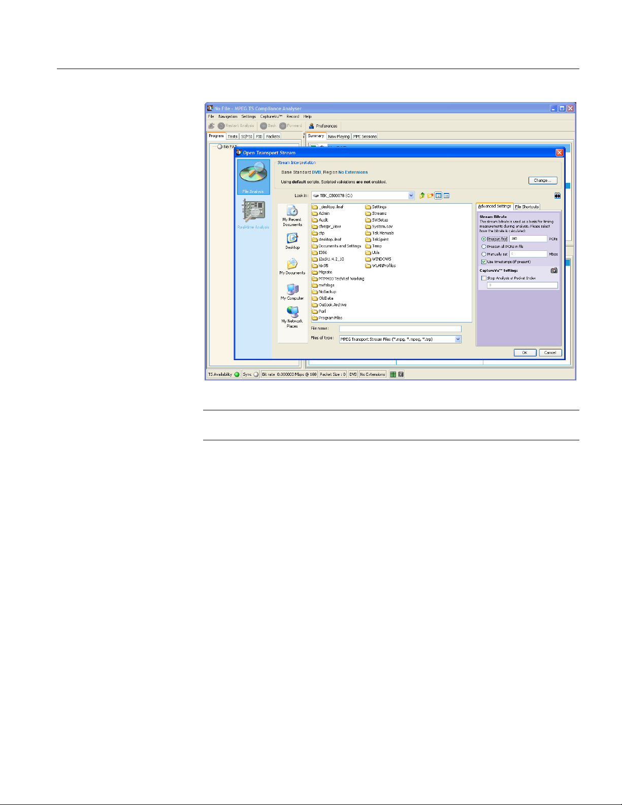
Stream Analysis Results
Figure 1-4 shows the result of off-line analysis. The layout of the real-time analysis
view is similar.
Figure 1-4: TSCA - File Open
MTS400 Series MPEG Test Systems Getting Started Manual 1-47
Page 68

Starting an Application
1-48 MTS400 Series MPEG Test Systems Getting Started Manual
Page 69

Operating Basics
Page 70

Page 71

Operating Basics
Software Applications
This section provides an overview of the software applications that make up the
MTS400 Series MPEG Test Systems. Note that some options might not be
enabled. Detailed descriptions of all applications can be found in the MTS400
Series system MPEG Test System User Manual.
The MTS4EA Compressed Video ES Analyzer options are described in the
MTS4EA User Manual (071-1641-xx).
Table 2-1: MTS400 / MTS430 / MTS4SA / MTS4UP installed applications (continued)
Application Desktop Icon1
Analyzers
Transport Stream Compliance Analyzer (TSCA) - Real Time
Real-time transport stream analysis with user-selectable MPEG-2, DVB, ATSC and ISDB conformance tests.
Shows transport structure, header contents, hexadecimal packet contents, PCR timing /transport rate graphs
and error message logs.
Transport Stream Compliance Analyzer (TSCA) - Deferred
Deferred transport stream analysis with user-selectable MPEG-2, DVB, ATSC and ISDB conformance tests.
Shows transport structure, header contents, hexadecimal packet contents, PCR timing /transport rate graphs
and error message logs.
Transport Stream Compliance Analyzer Lite (TSCA) - Deferred
Same as for the TS Analyzer except that the file size of transport streams to be analyzed is limited to 192 MB.
Packetized Elementary Stream (PES) Analyzer
PES analysis with selectable test options. Shows PES program structure, header contents, packet contents,
PTS/DTS timing graphs and analysis reports.
Transport Stream – System Target Decoder (T-STD) Buffer Analyzer
Analyzes program streams modeling their behavior in, and their conformance to, the MPEG-2 T-STD Buffer
Model. Includes a trace facility.
Elementary Stream Analyzer
Elementary Stream analysis at video picture and audio level. This includes vector graphs and macroblock
picture quality.
MTS400 Series MPEG Test Systems Getting Started Manual 2-1
Page 72

Operating Basics
Table 2-1: MTS400 / MTS430 / MTS4SA / MTS4UP installed applications (continued)
Application Desktop Icon1
Carousel Analyzer
Data analysis showing structure, bit rate, repetition rate, syntax and semantics of data items.
Generators
Carousel Generator
Provides in-depth, off-line generation of MPEG-2, DVB transport streams containing a range of data
broadcast protocols.
Multiplexer
Multiplexes table information and packetized elementary streams together to synthesize new transport
streams. A fine level of control is provided to allow nonconformances and test cases to be specified for new
transport streams.
TS Editor
Viewing and editing of transport stream packets, using a hexadecimal view of the packet contents and
semantic interpretation of the header. Provides facilities to remap PIDs, recalculate PCR values and introduce
PCR inaccuracies.
Players
MPEG Player
Records and plays MPEG-2 streams.
(The MTX100B/RTX100B/RTX130B players are described in their respective user manuals:
MTX100B User Manual, Tektronix part number 071-1927-xx, RTX100B User Manual, Tektronix part number
071-1930-xx, and RTX130B User Manual, Tektronix part number 071-1933-xx.)
Utilities
Make Seamless Wizard
Guides the user through the process of creating an MPEG-2 file for use by Stream Player in continuously
looped operation.
Stream Cutter
Extracts sections of MPEG-2 files to new files.
Script Pad
Enables users to create and modify System Information (SI) scripts.
1
If installed
2-2 MTS400 Series MPEG Test Systems Getting Started Manual
Page 73

Appendices
Page 74

Page 75

Appendix A: Cleaning and Maintenance
This appendix describes general care and service procedures for the MPEG Test
System.
Preventive Maintenance provides cleaning instructions.
In Case of Problems provides some hints for troubleshooting startup errors.
Repackaging for Shipment gives instructions for packing and shipping the
instrument.
General Care
Protect the instrument from adverse weather conditions. The instrument is not
waterproof.
CAUTION. To avoid damage to the instrument, do not expose it to sprays, liquids,
or solvents.
Do not use chemical cleaning agents; they may damage the instrument. Avoid
chemicals that contain benzene, toluene, xylene, acetone, or similar solvents.
Preventive Maintenance
Check the electrical performance and verify that the instrument accuracy is
certified (calibrated) once a year.
Preventive maintenance mainly consists of periodic cleaning. Periodic cleaning
reduces instrument breakdown and increases reliability. You should clean the
instrument as needed, based on the operating environment. Dirty conditions may
require more frequent cleaning than computer room conditions.
Cleaning the Exterior
Clean the exterior surfaces of the instrument with a dry, lint-free cloth or a softbristle brush. If dirt remains, use a cloth or swab dampened with a 75% isopropyl
alcohol solution. A swab is useful for cleaning in narrow spaces around the
controls and connectors. Do not use abrasive compounds on any part of the
instrument.
MTS400 Series MPEG Test Systems Getting Started Manual A-1
Page 76
Appendix A: Cleaning and Maintenance
CAUTION. Avoid getting moisture inside the instrument during external cleaning
and use only enough solution to dampen the cloth or swab. Use a 75% isopropyl
alcohol solution as a cleanser and rinse with deionized water.
Do not wash the front-panel On/Standby switch. Cover the switch while cleaning
the instrument.
Cleaning the Compact Disc Drive
The compact disc drive requires routine maintenance to operate at maximum
efficiency. The compact discs can be damaged if dirt and dust accumulate on the
surface of the discs. Store any discs in their protective containers to keep them
from being exposed to dust or dirt.
CAUTION. Electrostatic discharge (ESD) can damage components in the CD-ROM
drive. Do not touch lens or exposed metallic parts on the platter, with the
exception of the center hub.
Clean the face of the CD-ROM drive monthly with a cloth dampened with
deionized water.
Cleaning the Keyboard
CAUTION. Do not allow moisture to enter the disc drive. When power is applied,
the internal components might be damaged.
Clean the exterior surfaces of the keyboard and integrated tracking device with a
dry, lint-free cloth or a soft-bristle brush. A swab is useful for cleaning in narrow
spaces around the controls and connectors. Do not use abrasive compounds on any
part of the instrument.
CAUTION. Avoid getting moisture inside the keyboard and integrated tracking
device during external cleaning and use only enough solution to dampen the cloth
or swab. Use a 75% isopropyl alcohol solution as a cleanser and rinse with
deionized water.
A-2 MTS400 Series MPEG Test Systems Getting Started Manual
Page 77

Appendix A: Cleaning and Maintenance
In Case of Problems
This section addresses problems that you may encounter while using the test
system. This section does not identify specific problems related to performance
verification or adjustments. The diagnostic procedures for the MTS400 Series
system provided in this section can help you isolate problems. For a performance
verification procedure, refer to the MTS400 Series system MPEG Test System
Technical Reference, supplied as a PDF file on the MTS400 Series system MPEG
Test System Recovery CD-ROM.
Power-on diagnostics run when you first power on the instrument to start the test
system application. These diagnostics check the operating system and hardware for
correct operation. If error messages occur during the power-on diagnostics, there
may be a system error that prevents the MTS400 Series system software from
starting.
Table A-1 lists some of the symptoms of hardware problems (related to the
operating system and peripheral devices) and possible solutions.
Table A-1: Troubleshooting power-on failures
Symptom Possible causes and recommended actions
Instrument does not power on Verify that the power cord is connected to the
instrument and to the power source.
Check that the instrument receives power when you
push the On/Standby switch; check that fans start.
Check that power is available at the power source.
Contact your local Tektronix service center.
Instrument powers on but does not
complete the power-on sequence
Power-on diagnostics fail Contact your local Tektronix service center.
Instrument does not recognize
accessories such as monitor,
printer, or keyboard
Instrument will not power off with
On/Standby switch
Check for and remove any disk in the floppy disk
drive; make sure instrument boots from the hard disk
drive.
Check that accessories are properly connected or
installed.
Contact your local Tektronix service center.
Try powering off the instrument using the Windows
XP shutdown procedure. If the instrument still does
not power off, use the task manager to close down
tasks. Finally, try the hard shutdown procedure; push
and hold the On/Standby switch for five seconds to
power off the instrument.
MTS400 Series MPEG Test Systems Getting Started Manual A-3
Page 78

Appendix A: Cleaning and Maintenance
Software Problems
Your MPEG Test System comes with software already installed. For any suspected
software problems, try to isolate the problem to the test system application
software or to other installed software.
Many software problems are due to corrupt or missing software files. In most
cases, the easiest way to solve software problems is to reinstall the software. See
the Software Repair and Recovery appendix.
If you suspect networking problems, see Appendix C: Network Troubleshooting.
Hardware Problems
Hardware problems can have several causes. Review the installation instructions in
this manual to verify that you have properly installed the instrument. There are no
user serviceable parts in the MTS400 Series systems, so you should contact your
local Tektronix Service representative if you have a hardware problem.
Repackaging for Shipment
Your instrument was originally shipped by Tektronix in a carton with packaging
components designed to protect the instrument from damage during shipment. If
you need to ship the instrument to another location, it is strongly recommended
that you use the original shipping carton and packaging components to provide
adequate protection during shipment.
CAUTION. To prevent the invalidation of your instrument’s warranties, Tektronix
strongly recommends that you use your original shipping carton (one that is in
good condition) when you ship the instrument to another location or when you
return the instrument to a Tektronix service center for repair.
Tektronix cannot honor the instrument’s warranties if the instrument arrives at the
service center damaged and it was not shipped in its original carton or in a
replacement carton (and its supporting packaging material) purchased from
Tektronix. If you lose your original packaging material, contact your Tektronix
representative to obtain replacement packaging.
A-4 MTS400 Series MPEG Test Systems Getting Started Manual
Page 79

Appendix A: Cleaning and Maintenance
Packaging Inspection
When preparing to ship your instrument to another location, it is important to
inspect your packaging materials for condition and missing components.
If the condition of your packaging materials is poor, or if you are missing some of
the components, it is strongly recommended that you order a new packaging kit.
Replacement Packaging Materials
New packaging materials are available from Tektronix. To obtain these items,
contact your Tektronix representative.
The replacement packaging kit, Tektronix part number 065-0714-xx, includes all
the packaging material required to properly package the instrument for shipment.
Repackaging Procedure
When the instrument is shipped, it is important to package it well to protect the
instrument. It is not necessary to return the accessories received with the
instrument when returning the instrument for repair.
1. If the instrument is to be shipped to a Tektronix field office for repair, attach a
tag to the instrument showing the following:
Owner’s name and address
Instrument serial number
Description of the problem(s) encountered and/or service required.
2. Place the protective front cover on the front of the instrument.
3. Place the instrument in the protective bag. The bag prevents dust, moisture,
and other debris from entering the cabinet.
4. Fold the top of the bag neatly over the top of the instrument to make it as flat
as possible and seal with packing tape.
5. Place the front cushion over the front of the instrument.
6. Place the rear cushion over the rear of the instrument.
7. Carefully lift the instrument with front and rear cushions attached and lower it
into the shipping box.
8. Position the cardboard tray into the top of the box, pressing the tray down
until it rests on the tops of the front and rear cushions.
MTS400 Series MPEG Test Systems Getting Started Manual A-5
Page 80

Appendix A: Cleaning and Maintenance
NOTE. To ensure packaging integrity and product safety, the tray must be installed
regardless of whether accessories are being included in the package.
9. If you are shipping the accessories, arrange the accessories in the tray.
10. Close and tape the shipping box.
11. Attach the appropriate shipping documents needed to ship the instrument to
its destination.
A-6 MTS400 Series MPEG Test Systems Getting Started Manual
Page 81

Appendix B: MTS400 Series System Recovery
If you have problems with the MTS400 Series system software, use the procedures
in this section to restore the system to factory default installation and
configuration.
NOTE. If you are restoring software after replacing the hard disk drive with one
that you ordered from Tektronix, follow the instructions provided with the hard
disk replacement kit.
NOTE. The procedures described in this section are not applicable to the
MTX100B/RTX100B/RTX130B.
Overview
These procedures require the MTS400 Series system Recovery media, which were
shipped with your system (see Table B-1).
Table B-1: MTS400 Series system recovery media
Quantity Description Part number
1 ea Software package: Operating System Restore DVD,
MTS400 MPEG Test System
1 ea Software package: MTS400 MPEG Test System Installation
CD-ROM
Only a qualified technician who is familiar with installing drivers and configuring
systems for networking should perform this installation.
These tips apply to the procedures in this section:
063-3971-xx
063-3814-xx
Use default settings unless otherwise indicated in the following procedures.
These procedures use drive “D:” as the CD-ROM drive.
At the end of some steps, you are instructed to restart the system. To do this,
if you are prompted to restart, select Yes. If not prompted, select Shutdown
from the Start menu and then select Restart the computer.
MTS400 Series MPEG Test Systems Getting Started Manual B-1
Page 82

Appendix B: MTS400 Series System Recovery
The procedures in this appendix tell you how to:
Restore the operating system to factory default
Reinstate the SCSI drives (if required)
Install MTS400 Series system applications
Reinstate the software license option key
Reformat the SCSI drives (if required)
The complete system includes:
• Microsoft Windows XP Professional with Service Pack 2B
• Internet Explorer 6.0 SP2
• SigmaTel C-Major Sound Driver
• Mobility Radeon 7500 Display Driver (ATI)
• Tektronix Soft Power Down Driver & Shutdown Service
• Intel EtherExpress PRO/100B and PRO/1000 PCI Adapter Driver
• Symbios SCSI Driver
• Nero CD/DVD recording software
• Intel Application Accelerator
• Intel INF Update
• Media Player 10
• Tektronix MTS400 Series system MPEG Test Systems application software
B-2 MTS400 Series MPEG Test Systems Getting Started Manual
Page 83

Appendix B: MTS400 Series System Recovery
Restore Operating System
In some situations, such as when the power is interrupted or files are mistakenly
deleted, the system might fail to boot from the hard drive. If this happens, use the
MTS400 Series System Recovery media to restore the hard drive to factory default
installation status.
CAUTION. To avoid losing access to your licensed applications, you must use the
MTS400 Series system Recovery media supplied with the unit (or subsequent
upgrade).
MTS400 Series System Operating System Restore
To restore the MTS400 Series system operating system, use the following steps.
This restore process is effective only if the hard disk drive is still good. The
process will restore the operations system and the application software. (The
process should take less than 30 minutes.)
CAUTION. To prevent data loss, back up your hard drive before you restore the
MTS400 Series system. All data on the hard drive will be destroyed during the
system restore process.
1. Start the MTS400 Series system with the MTS400 Series System Operating
System Restore DVD in the CD-ROM drive. The system will autostart the
recovery application.
2. Push the “1” key to begin the system restore process. The Acquiring Device…
dialog box will appear briefly and display a progress bar.
3. When the system restore is complete, remove the DVD from the CD-ROM
drive, push any key and then push the “4” key.
4. When prompted, push the “Y” key to reboot the instrument.
5. On startup, the system will prompt you to set up Windows XP. Follow the on-
screen procedure, accepting defaults where necessary.
6. Allow the system to restart when prompted.
MTS400 Series MPEG Test Systems Getting Started Manual B-3
Page 84

Appendix B: MTS400 Series System Recovery
Reinstate the SCSI Drives
After restoring the operating system, confirm that the SCSI drives (drives E and F)
have been recognized by the system. Figure B-1 shows the drives in the Windows
Explorer.
Figure B-1: SCSI drives automatically recognized
If the drives (E and F) are not listed in Windows Explorer, complete the following
procedure to allow them to be recognized by the system.
1. Open the Windows Disk Management window (Start > Control Panel >
Performance and Maintenance > Administrative Tools > Computer
Management > Storage > Disk management).
Note that Disk 0 and Disk 1 are described as Foreign, as shown in
Figure B-2.
B-4 MTS400 Series MPEG Test Systems Getting Started Manual
Page 85

Appendix B: MTS400 Series System Recovery
Figure B-2: Computer Management - SCSI drives, foreign
2. Right-click on Disk 0 or Disk 1 and select Import Foreign Disks… from the
shortcut menu (see Figure B-3).
Figure B-3: Select Import Foreign Disks…
MTS400 Series MPEG Test Systems Getting Started Manual B-5
Page 86

Appendix B: MTS400 Series System Recovery
3. In the Import Foreign Disks dialog box, ensure that the disk group is checked
and select OK.
Figure B-4: Import Foreign Disks dialog box
4. In the Foreign Disk Volumes dialog box, select OK.
Figure B-5: Foreign Disk Volumes dialog box
B-6 MTS400 Series MPEG Test Systems Getting Started Manual
Page 87

Appendix B: MTS400 Series System Recovery
The disk display should now be as shown in Figure B-6.
Figure B-6: SCSI drives manually recognized
This completes the MTS400 Operating System Restore Procedure.
MTS400 Series MPEG Test Systems Getting Started Manual B-7
Page 88

Appendix B: MTS400 Series System Recovery
Install the MTS400 Series System Applications
The procedure for installing the MTS400 Series system applications on either an
MTS400 or an MTS430 is similar to the procedure for stand-alone installations
(see page 1-27).
In the procedure described on page 1-29 (MTS4SA Stand-Alone System
Installation section), select MTS400 Platform (shown in Figure B-7) and continue
with the installation.
Figure B-7: MTS400 Installation – Setup Type
Note that after installing the MTS400 applications, the software license key must
be reinstated - this is also described in the stand-alone installation procedure (see
page 1-27).
B-8 MTS400 Series MPEG Test Systems Getting Started Manual
Page 89

Appendix B: MTS400 Series System Recovery
Reformat the SCSI Drives
CAUTION. All data stored on the SCSI drives will be lost when they are reset.
Ensure that any important data is backed up.
Two SCSI (small computer system interface) hard drives are used for MPEG file
storage. If the drives have become corrupted, they should be reset using the
following procedure:
1. Insert the MTS400 Series system Operating System Restore DVD in the CD-
ROM drive. Locate the SCSI_DRV folder.
2. Copy the whole SCSI_DRV folder to the C: drive. The folder contains the
following files:
drives.bat
readme.doc
complete.txt
complete2.txt
3. Remove the MTS400 Series system Operating System Restore DVD.
4. In the SCSI_DRV folder, run the file drives.bat (double-click on the file
name).
5. When the process is complete, restart the instrument.
MTS400 Series MPEG Test Systems Getting Started Manual B-9
Page 90

Appendix B: MTS400 Series System Recovery
B-10 MTS400 Series MPEG Test Systems Getting Started Manual
Page 91

Appendix C: Network Troubleshooting
Networks are based on standards; however, there are many unique characteristics
of each network (LAN or WAN) that make it difficult to troubleshoot without a
thorough knowledge of the specific network. Consequently, an expert who knows
your network characteristics should perform in-depth network troubleshooting.
This appendix provides some basic procedures that can eliminate some of the more
common sources of network errors. If you cannot resolve problems using these
procedures, contact your network administrator.
Basic Requirements
Fulfill the following requirements before troubleshooting your host machines:
Configure your system for use on the network as described in the
documentation that is supplied with the Network Adapter card. Contact your
network administrator for details.
Ensure that any applications that you may have loaded on your test system
since receiving it are not using the ports assigned to the test system
components.
MTS400 Series MPEG Test Systems Getting Started Manual C-1
Page 92

Appendix C: Network Troubleshooting
IP Parameters
The illustrations in this section show how each IP parameter (IP address, subnet
mask, and default gateway) can negatively affect network connectivity.
Incorrect IP Address
If the IP address for your test system is incorrect (not unique), then you may not be
able to communicate over the network. In Figure C-1, TVTest_1 uses the same IP
address as Rennes. If Rennes is started first, TVTest_1 will recognize the IP
address conflict and will not load TCP/IP; consequently, the system cannot be
reached over the network.
If your IP address is incorrect, and the IP address does not exist on your subnet,
you may be able to communicate from the device (system or monitoring station),
but you may not be able to communicate to the device.
Test system:
Rennes
Figure C-1: Incorrect IP address
Test system:
TVTest_2
IP address: 128.193.99.2
Test system:
TVTest_1
No TCP/IP
communication
IP address: 128.181.99.62 IP address: 128.181.99.62
C-2 MTS400 Series MPEG Test Systems Getting Started Manual
Page 93

Appendix C: Network Troubleshooting
Incorrect Subnet Mask
Subnets and subnetting networks are complex and require a thorough
understanding of IP addressing. Call your network administrator if you think your
networking problem involves subnets. Figure C-2 shows a simple (and fairly
common) subnet mask problem.
In Figure C-2, the subnet mask for TVTest_1 indicates that the network address is
contained in the first two bytes of the IP address. In dotted decimal notation, the
network address is 128.181. This information allows the device to communicate
with any other device with the same network address without being routed through
a default gateway.
Subnet mask: 255.255.255.0
IP address: 128.181.96.201
Router
Test system:
Rennes
IP address: 128.181.99.82 IP address: 128.181.99.72
Subnet mask: 255.255.255.0
Test system:
Carnac
Test system:
TVTest_2
Subnet mask: 255.255.255.0
Figure C-2: Incorrect subnet mask
TVTest_1 cannot communicate with Carnac, because, according to the subnet
mask on TVTest_1, Carnac and TVTest_1 are logically on the same network.
Consequently, messages sent from TVTest_1 to Carnac are never routed. Because
these two devices do not share a connection, TVTest_1 will never find the correct
address for the network card on Carnac and will not be able to reach Carnac.
No TCP/IP
communication
Test system:
TVTest_1
IP address: 128.181.99.62
Subnet mask: 255.255.0.0
TVTest_1 can communicate with TVTest_2 and Rennes because these three
devices share a connection, so messages from TVTest_1 do not need to be routed.
TVTest_1 is therefore able to find the correct addresses for TVTest_2 and Rennes
in spite of having an incorrect subnet mask.
MTS400 Series MPEG Test Systems Getting Started Manual C-3
Page 94

Appendix C: Network Troubleshooting
_
Incorrect Default Gateway IP Address
The default gateway you have specified in the TCP/IP Properties dialog box is the
device that “knows about” your subnetwork and others on your network. When
you send messages (for instance traps from your system to a device on another
subnet), the default gateway is able to route the message to the appropriate subnet.
If the IP address specified in the TCP/IP Properties dialog box is incorrect,
messages to devices on other subnets will not reach their destination (because they
never made it to the default gateway). See Figure C-3.
IP address: 128.181.96.201
Subnet mask: 255.255.255.0
Default gateway: 128.181.96.1
Test system:
Carmac
Gateway
(router)
IP address: 128.181.99.1
Test system:
Rennes
IP address: 128.181.99.82 IP address: 128.181.99.72
Gateway
(router)
Subnet mask: 255.255.255.0 Subnet mask: 255.255.255.0
Default gateway: 128.181.99.1 Default gateway: 128.181.99.1
WAN
Test system:
TVTest_2
IP address: 128.181.96.1
communication
No TCP/IP
Test system:
TVTest
IP address: 128.181.99.62
Subnet mask: 255.255.255.0
Default gateway: 128.181.99.10
1
Figure C-3: Incorrect default gateway IP address
C-4 MTS400 Series MPEG Test Systems Getting Started Manual
Page 95

Appendix C: Network Troubleshooting
Common Troubleshooting Procedures
Many of the procedures performed in the following sections are common tasks.
Pinging a Host Machine
One of the utilities provided with all TCP/IP installations is Ping.exe. (Look in the
C:\windows\system32\ directory.) This utility allows you to send communication
packets to and record the response from an indicated host machine. This
determines whether your packets arrived at the destination. To run ping, use the
following procedure:
1. Select Run from the Start menu. The Run dialog box appears.
2. Type one of the following into the Run text box:
ping machineName
ping IPaddress
In the examples, machineName and IPaddress represent the host machine
name and IP address, respectively, of the networked device you are trying to
ping.
3. Click OK.
A DOS window indicates whether or not the machine is responding to the
ping. In Figure C-4, the destination machine (Oxford4) is not responding.
MTS400 Series MPEG Test Systems Getting Started Manual C-5
Page 96

Appendix C: Network Troubleshooting
Figure C-4: Ping.exe command window
Ping only runs briefly, and the DOS window closes when the process is complete.
Tracing the Route of TCP/IP Packets
Sometimes it is helpful to know how far your packets made it on the way to a
destination machine and which devices the packets pass through on the way. The
utility that provides this functionality is tracert.exe. Tracert can also indicate
a congested point in the network. To run tracert, use the following procedure:
1. Select Run from the Start menu. The Run dialog box appears.
2. Type one of the following into the Run text box:
tracert machineName
tracert IPaddress
In the examples, machineName and IPaddress represent the host machine
name and IP address, respectively, of the networked device you are trying to
reach.
3. Click OK.
A DOS window (see Figure C-5) indicates the progress of your packets. The
far right column indicates the IP address of the nodes on the network that
successfully pass your tracert packets. This information indicates the last
good node on the path to the destination device.
C-6 MTS400 Series MPEG Test Systems Getting Started Manual
Page 97

Appendix C: Network Troubleshooting
Figure C-5: Tracert.exe command window
Finding IP Addresses for Devices on Your Network
At times, you may need to find or confirm the IP address of a computer on your
network (or find the network name if all you have is an IP address). You may want
to find this information to ensure that IP addresses and network names you use in
the Hosts file are correct. The utility that will display this information is
nslookup.exe. Use nslookup as described below:
1. Select Run from the Start menu. The Run dialog box appears.
2. Enter one of the following and push Enter, where machineName or IPaddress
is the network name or IP address, respectively, of the device you are trying
to look up.
nslookup machineName
nslookup IPaddress
The network name and IP address of the device you are trying to look up is
displayed. If your network uses DNS, the IP address and network name of the
DNS server is also displayed. See Figure C-6.
MTS400 Series MPEG Test Systems Getting Started Manual C-7
Page 98

Appendix C: Network Troubleshooting
Figure C-6: Command prompt with nslookup results
Sources of Network Information
If you need more information about network troubleshooting, some potential
resources are listed below.
NOTE. These resources may provide you with more information. Most of this
information is supplied as is, with no warranty as to its fitness, written or implied.
The best source of network troubleshooting help is your network administrator.
Cisco Systems, Inc. http://www.cisco.com/
This site is particularly useful for networks that use Cisco devices. (This URL
was valid as of January 2005.)
Dulaney, E; Lawrence, S; Scrimger, R; Tilke, A; White, J; Williams, R;
Wolford, K. MCSE Training Guide: TCP/IP. Indianapolis, IN.
New Riders, 1998
This is a training guide for Microsoft Certified Systems Engineer certification,
and covers TCP/IP and network troubleshooting.
Taylor, E. Network Troubleshooting Handbook. New York, NY. McGraw–
Hill, 1999
C-8 MTS400 Series MPEG Test Systems Getting Started Manual
Page 99

Glossary
Page 100

 Loading...