

Tektronix MTS4KUP ESS, MTS4SA MPEG, MTS4KUP ESE, MTS4KUP GEN, MTS4KUP PQ Instructions Manual
...Page 1

xx
MTS4KUP
10GS, ASI, ESE, ESS, GEN, IPTV, LX, PB, PQ, QB2, S2, SX,
VQ, VS, and ZX
ZZZ
MTS4000 Upgrade Kits
Instructions
*P075103600*
075-1036-00
Page 2

Page 3

xx
MTS4KUP
10GS, ASI, ESE, ESS, GEN, IPTV, LX, PB, PQ, QB2, S2, SX, VQ,
VS, and ZX
ZZZ
MTS4000 Upgrade Kits
Instructions
www.tektronix.com
075-1036-00
Page 4

Copyright © Tektronix. All rights reserved. Licensed software products are owned by Tektronix or its subsidiaries
or suppliers, and are protected by national copyright laws and international treaty provisions.
Tektronix products are covered by U.S. and foreign patents, issued and pending. Information in this publication
supersedes that in all previously published material. Specifications and price change privileges reserved.
TEKTRONIX and TEK are registered trademarks of Tektronix, Inc.
Contacting Tektronix
Tektronix, Inc.
14150 SW Karl Braun Drive
P.O. B o x 5 0 0
Beaverto
USA
For product information, sales, service, and technical support:
n, OR 97077
In North America, call 1-800-833-9200.
Worl dwid e, visi t www.tektronix.com to find contacts in your area.
Page 5

Table of Contents
General Safety Summary ......................................................................................... iv
Service Safety Summary...................................... ................................ .................... vi
Kit description ........................................... .................................. ....................... vii
Kit parts li
Software upgrade instructions.................................... .................................. ............... 5
Hardware upgrade instructions.................................................................................... 7
Optical SFP upgrades ............................................................................................. 17
sts ................... ................................ .................................. ................... 1
MTS4000 Upgrade Kit Instructions i
Page 6

Table of Contents
List of Figure
Figure 1: IPTV interface card bumper installation ............................................................. 8
Figure 2: QB
Figure 3: Remove rear panel ........... ................................ .................................. ........ 10
Figure 4: CIP cable installation on option IPTV interface card .................. ............................ 12
Figure 5: COM connectors on motherboard............................ ................................ ........ 13
Figure 6: CIP cable installation on option QB2, S2, and VS interface cards . .............................. 14
Figure 7: Sample SFP optical module........................................................................... 17
2, S2, and VS interface cards bumper installation............................................... 8
s
ii MTS4000 Upgrade Kit Instructions
Page 7

List of Tables
Table 1: Recommended tool list . ................................ .................................. ............... 7
Table 2: Int
erface card slot locations ............................ .................................. ............... 9
Table of Contents
MTS4000 Upgrade Kit Instructions iii
Page 8

General Safety Summary
General Safet
To Avoid Fi
re or Personal
Injury
ySummary
Review the fo
this product or any products connected to it.
To avoid pot
Only qualified personnel should perform service procedures.
Use proper
certified for the country of use.
Ground th
of the power cord. To avoid electric shock, the grounding conductor must be
connected to earth ground. Before making connections to the input or output
terminals of the product, ensure that the product is properly grounded.
Observe all terminal ratings. To a voi d fire or shock hazard, observe all ratings
and markings on the product. Consult the product manual for further ratings
information before making connections to the product.
The inputs are not rated for connection to mains or Category II, III, or IV circuits.
Do not apply a potential to any terminal, including the common terminal, that
exceeds the maximum rating of that terminal.
llowing safety precautions to avoid injury and prevent damage to
ential hazards, use this product only as specified.
power cord. Use only the power cord specified for this product and
eproduct.This product is grounded through the grounding conductor
Power disconnect. The power cord disconnects the product from the power source.
Donotblockthepowercord;itmustremain accessible to the user at all times.
Do not operate without covers. Do not operate this product with covers or panels
removed.
Do not operate with suspected failures. If you suspect that there is damage to this
product, have it inspected by qualified service personnel.
Avoid exposed circuitry. Do not touch exposed connections and components when
power is present.
Wear eye protection. Wear eye protection if exposure to high-intensity rays or
laser radiation exists.
Do not operate in wet/damp conditions.
Do not operate in an explosive atmosphere.
Keep product surfaces clean and dry.
Provide proper ventilation. Refer to the manual's installation instructions for details
on installing the product so it has proper ventilation.
iv MTS4000 Upgrade K it Instructions
Page 9

General Safety Summary
TermsinThisManual
Symbols and Terms on the
Product
These terms may
WAR NI NG . Warning statements identify conditions or practices that could result
in injury or loss of life.
CAUTION. Caution statements identify conditions or practices that could result in
damage to this product or other property.
These terms may appear on the product:
DANGER in
the marking.
WARNING
read the marking.
CAUTIO
The following symbol(s) may appear on the product:
appear in this manual:
dicates an injury hazard immediately accessible as you read
indicates an injury hazard not immediately accessible as you
N indicates a hazard to property including the product.
MTS4000 Upgrade Kit Instructions v
Page 10

Service Safety Summary
Service Safet
y Summary
Only qualifie
Safety Summary and the General Safety Summary before performing any service
procedures.
Do Not Service Alone. Do not perform internal service or adjustments of this
product unless another person capable of rendering first aid and resuscitation is
present.
Disconnect Power. To avoid electric shock, switch off the instrument power, then
disconnect the power cord from the mains power.
Use Care When Servicing With Power On. Dangerous voltages or currents may
exist in
disconnect test leads before removing protective panels, soldering, or replacing
components.
To avoid electric shock, do not touch exposed connections.
d personnel should perform service procedures. Read this Service
this product. Disconnect power, remove battery (if applicable), and
vi MTS4000 Upgrade Kit Instructions
Page 11

Kit description
Kit description
This document provides instructions for performing hardware and/or software and
option key upgrades on the following Tektronix products:
MTS4000 MPEG Test System
MTS4SA MPEG Test System
Upgrade kits covered by
these instructions
MTS4KUP GEN – Multiplexer, MPEG Playe
Make Seamless Wizard, Transport Stream Cutter, and Script Pad.
Includes Tclips test streams media.
MTS4KUP ESS – Standard ES analysis. Includes MTS4CC with all options
plus MPEG-2 ES Analyzer.
MTS4KUP ESE – Enhanced ES analysis. Includes MTS4EAB with all
options plus MPEG-2 ES Analyzer.
MTS4KUP VQ – Video quality software, single e nded. Includes VQS1000
with all options.
MTS4KUP PQ – Picture quality analysis software, single and double ended.
Includes PQASW with IP option.
MTS4KUP PB – PES and T-STD Buffer Analyzers.
MTS4KUP ASI – Adds the Multiport A SI interface (four ports).
MTS4KUP S2 – Adds the DVB-S/S2 interface supporting QPSK, 8PSK,
16APSK AND 32APSK demodulation. (Requires Option ASI.)
MTS4KUP VS – Adds the 8VSB interface. (Requires Option ASI.)
MTS4KUP QB2 – Adds the QAM B interface. (Requires Option A SI.)
r, Transport Stream Editor,
MTS4KUP 10GS – Adds the 10GBASE-SR dual optical port 10Gb/s NIC.
Includes short reach SFP+ modules (850 nm).
MTS4KUP IPTV – Adds the IPTV Gigabit Ethernet Interface with
10/100/1000 Base-T RJ45 Electrical Port. (Requires Option ASI.)
The following optical length input options are available for use with option
IPTV:
MTS4KUP SX – 1000 Base-SX Short Wavelength Optical Port with LC
Connector for IPTV Ethernet Interface (Multi Mode 850 nm)
MTS4KUP LX – 1000 Base
Connector for IPTV Ethernet Interface (Single Mode 1310 nm)
MTS4KUP ZX – 1000BASE-ZX optical port with LC connector for IPTV
Ethernet interface (single mode 1550 nm).
MTS4000 Upgrade Kit Instructions vii
-LX Long Wavelength Optical Port with LC
Page 12

Kit description
viii MTS4000 Upgrade Kit Instructions
Page 13

Kit parts lists
MTS4KUP GEN
MTS4KUP ESS
MTS4KUP ESE
Quantity Part Num ber Description
1
1 020-2965-xx
1 075-1036-xx
1 071-2179-xx
Quantity Part Num be
1
1
1 075-1036-xx
1 071-2179-xx
Quantity Part Num ber Description
1
1
1 075-1036-xx
1 071-2179-xx
N/A MTS4000 OPTION KEY LABEL
TCLIPS MPEG TEST STREAMS DVD PACKAGE
MTS4KUP UPGRADE KIT INSTRUCTIONS
MANUAL, TECH; SMPLP; TEKTRONIX SUPPLEMENTAL
INFORMATION SHEET FOR THE P EOPLES REPUBLIC OF
CHINA; CHINA ROHS
r
Descripti
N/A MTS4000 O
N/A CD FOR DO
MTS4KUP
MANUAL
INFORMATION SHEET FOR THE P EOPLES REPUBLIC OF
CHINA; CHINA ROHS
N/A MTS4000 OPTION KEY LABEL
N/A CD FOR DO NGLE UPDATE
MTS4KUP UPGRADE KIT INSTRUCTIONS
MANUAL, TECH; SMPLP; TEKTRONIX SUPPLEMENTAL
INFORMATION SHEET FOR THE P EOPLES REPUBLIC OF
CHINA; CHINA ROHS
on
, TECH; SMPLP; TEKTRONIX SUPPLEMENTAL
PTION KEY LABEL
NGLE UPDATE
UPGRADE KIT INSTRUCTIONS
S4KUP VQ
MT
Quantity Part Num ber Description
1
1 075-1036-xx
1 071-2179-xx
N/A VQS1000 OPTION KEY LABEL
MTS4KUP UPGRADE KIT INSTRUCTIONS
MANUAL, TECH; SMPLP; TEKTRONIX SUPPLEMENTAL
NFORMATION SHEET FOR THE PEOPLES REPUBLIC OF
I
CHINA; CHINA ROHS
MTS4000 Upgrade Kit Instructions 1
Page 14

Kit parts lists
MTS4KUP PQ
MTS4KUP PB
MTS4KUP ASI
Quantity Part Number Description
1
1 020-3054-xx
1 075-1036-xx
1 071-2179-xx
Quantity Part Number Description
1
1 075-1036-xx
1 071-2179-xx
Quantity Part Number Description
1
1
1 075-1
1 071-
N/A PQA600 OPTION KEY LABEL
PQA600 APPLICATION SOFTWARE KIT
MTS4KUP UPGRADE KIT INSTRUCTIONS
MANUAL, TE CH; SMPLP; TEKTRONIX SUPPLEMENTAL
INFORMATIO
CHINA; CHINA ROHS
N/A MTS4000 OPTIO N KEY LABEL
MTS4KUP UPGRADE KIT INSTRUCTIONS
MANUAL, TE CH; SMPLP; TEKTRONIX SUPPLEMENTAL
INFORMATION SHEET FOR THE PEOPLE S REPUBLIC OF
CHINA; CHINA ROHS
N/A QUAD ASI/SDI ADAPTER CIRCUIT BD ASSEMBLY
N/A MTS4000 OPTIO N KEY LABEL
036-xx
2179-xx
MTS4KUP UPGRADE KIT INSTRUCTIONS
MANUAL, TE CH; SMPLP; TEKTRONIX SUPPLEMENTAL
INFORMATION SHEET FOR THE PEOPLE S REPUBLIC OF
A; CHINA ROHS
CHIN
N SHEET FOR THE PEOPLES REPUBLIC OF
MTS4KUP S2
Quantity Part Number Description
1
1 174-5135-00
1 174-6103-00
1 348-2003-00
1 075-1036-xx
1 071-2179-xx
N/A BASE BAND AND DVB-S2 CIRCUIT BD ASSEMBLY
CABLE ASSY; RF, BNC TO BNC;75 OHM
CABLE, ASSEMBLY
BUMPER, RUBBER; CLEAR, 0.375 DIA X 0.200 H
MTS4KUP UPGRADE KIT INSTRUCTIONS
MANUAL, TE CH; SMPLP; TEKTRONIX SUPPLEMENTAL
INFORMATION SHEET FOR THE PEOPLE S REPUBLIC OF
CHINA; CHINA ROHS
2 MTS4000 Upgrade Kit Instructions
Page 15

Kit parts lists
MTS4KUP VS
MTS4KUP QB2
Quantity Part Num ber Description
1
1 174-5135-00
1 348-2003-00
1 075-1036-xx
1 071-2179-xx
Quantity Part Num ber Description
1
1 174-5135-00
1 174-6103-00
1 348-2003-00
1 075-1036-xx
1 071-2179-xx
N/A BASE BAND AND 8VSB CIRCUIT BD ASSEMBLY
CABLE ASSY; RF, BNC TO BNC;75 OHM
BUMPER, RUBBER; CLEAR, 0.375 DIA X 0.200 H
MTS4KUP UPGRADE KIT INSTRUCTIONS
MANUAL, TECH; SMPLP; TEKTRONIX SUPPLEMENTAL
INFORMATI
CHINA; CHINA ROHS
N/A BASE BAND AND QB2 CIRCUIT BD ASSEMBLY
CABLE ASSY; RF, BNC TO BNC;75 OHM
CABLE, ASSEMBLY
BUMPER, RUBBER; CLEAR, 0.375 DIA X 0.200 H
MTS4KUP UPGRADE KIT INSTRUCTIONS
MANUAL, TECH; SMPLP; TEKTRONIX SUPPLEMENTAL
INFORMATION SHEET FOR THE P EOPLES REPUBLIC OF
CHINA; CHINA ROHS
ON SHEET FOR THE PEOPLES REPUBLIC OF
MTS4KUP 10GS
MTS4KUP IPTV
Quantity Part Num ber Description
1
1 075-1036-xx
1 071-2179-xx
Quantity Part Num ber Description
1
1 174-5135-00
1 174-6103-00
1 348-2003-00
1 075-1036-xx
1 071-2179-xx
N/A 10G ETHERNET ADAPTER WITH SFP+ CONNECTIVITY
CIRCUIT BD ASSEMBLY
MTS4KUP UPGRADE KIT INSTRUCTIONS
MANUAL, TECH; SMPLP; TEKTRONIX SUPPLEMENTAL
FORMATION SHEET FOR THE PEOPLES REPUBLIC OF
IN
CHINA; CHINA ROHS
N/A IPTV CIRCUIT BD ASSEMBLY
CABLE ASSY; RF, BNC TO BNC;75 OHM
CABLE, ASSEMBLY
BUMPER, RUBBER; CLEAR, 0.375 DIA X 0.200 H
MTS4KUP UPGRADE KIT INSTRUCTIONS
MANUAL, TECH; SMPLP; TEKTRONIX SUPPLEMENTAL
INFORMATION SHEET FOR THE P EOPLES REPUBLIC OF
CHINA; CHINA ROHS
MTS4000 Upgrade Kit Instructions 3
Page 16

Kit parts lists
MTS4KUP SX
MTS4KUP LX
MTS4KUP ZX
Quantity Part Number Description
1 131-7834-00
1 075-1036-xx
1 071-2179-xx
Quantity Part Number Description
1 131-7957-00
1 075-1036-xx
1 071-2179-xx
QuantityPart Num
1 131-7958-00
1 075-1
1 071-2
ber
036-xx
179-xx
OPTICAL GIGA BIT ETHERNET/FIBRE CHANNEL 850NM
SFP, 1.25/1.0
MTS4KUP UPGR
MANUAL, TEC
INFORMATION SHEET FOR THE PEOPLE S REPUBLIC OF
CHINA; CHINA ROHS
OPTICAL GIGABIT ETHERNET/FIBRE CHANNEL 1310NM
SFP SFF, 1.25/1.0625GBAUD, 3.3V
MTS4KUP UPGRADE KIT INSTRUCTIONS
MANUAL, TE CH; SMPLP; TEKTRONIX SUPPLEMENTAL
INFORMATION SHEET FOR THE PEOPLE S REPUBLIC OF
CHINA; CHINA ROHS
Descrip
OPTICA
SFP, 1.25/1.0625GBAUD, 3.3V
MTS4KUP UPGRADE KIT INSTRUCTIONS
MANUAL, TE CH; SMPLP; TEKTRONIX SUPPLEMENTAL
INFORMATION SHEET FOR THE PEOPLE S REPUBLIC OF
CHIN
tion
L GIGABIT ETHERNET/FIBRE CHANNEL 1550NM
A; CHINA ROHS
625GBAUD, 3.3V
ADE KIT INSTRUCTIONS
H; SMPLP; TEKTRONIX SUPPLEMENTAL
4 MTS4000 Upgrade Kit Instructions
Page 17

Software upgrade instructions
Many of the upgrades available for the MTS4000 are software only; there is no
hardware to install. These software upgrades are also available for the MTS4SA.
The software only upgrades are:
MTS4KUP ESE MTS4KUP PB MTS4KUP GEN
MTS4KUP ESS MTS4KUP PQ MTS4KUP VQ
Software only upgrades require that the pre-installed software be unlocked. Use
he following procedure(s) to unlock the software.
t
MTS4KUP ESE, ESS, PB,
and GEN key entry
1. Check that the USB software key (dongle) is installed in one of the USB ports.
2. Power on the instrument.
3. Start the MTS4000 Option Key Wizard. Select Start > Programs >
Tektronix MTS4000 > OptionKey Wizard.
4. In the Tektronix Option Update dialog box, enter the Option Key String
supplied with the installation documentation in the Key String field.
5. Click Apply.
6. Verify that the Option is enabled in the MPEG Applications list.
MTS4000 Upgrade Kit Instructions 5
Page 18

Software upgrade instructions
MTS4KUP PQ license entry
7. ESE or ESS Optio
a. Insert the CD, provided in the kit, into the CD/DVD drive.
b. Navigate to the CD and display its contents. Double click the
remoteupdate.exe file to update the dongle.
c. Follow any on-screen instructions.
d. When completed, remove the CD.
8. Peel the backing off of the Product Option Key label and apply it to the
instrument rear panel.
Option PQ enables the PQA600 software that is installed on the
MTS4000 instrument.
1. Power on the instrument.
2. Launch t
3. From the PQA600 toolbar, go to Help > License Manager.
4. Enter the License string supplied with the installation documentation.
5. Peel the backing off of the PQA Product Option label and apply it to the
instrument rear panel. Do not cover any existing labels.
he PQA600 software.
ns only:
MTS4KUP VQ license entry
Option VQ enables the VQS1000 software that is installed on the
MTS4000 instrument.
1. Power on the instrument.
2. Launch the VQS1000 software.
om the VQS1000 toolbar, go to Help > License Manager.
3. Fr
4. Enter the License string supplied with the installation documentation.
5. Peel the backing off of the VQS Product Option label and apply it to the
instrument rear panel. Do not cover any existing labels.
6 MTS4000 Upgrade Kit Instructions
Page 19

Hardware upgrade instructions
Interface card upgrades available for the MTS4000 require the installation of
hardware internal to the instrument. These upgrades are:
MTS4KUP 10GS MTS4KUP IPTV MTS4KUP S2
MTS4KUP ASI MTS4KUP QB2 MTS4KUP VS
These instructions are for personnel who are familiar with servicing the product.
Contact your nearest Tektronix, Inc., Service Center or Tektronix Factory Service
for installation assistance.
NOTE. Up to four optional interface cards can be installed into the instrument,
but only t
CAUTION. To prevent static discharge damage, service the product only
in a stat
static-sensitive devices while installing this kit. Always wear a grounded wrist
strap, grounded foot strap, and static resistant apparel while installing this kit.
wo of the following options: S2, VS, QB2, IPTV.
ic-free environment. Observe standard handling precautions for
Recommended tool list
Table 1: Recommended tool list
Description
Anti-static wrist strap
Screwdriver handle with P2 tip
9/16 inch socket and wrench (Option ASI only)
MTS4000 Upgrade Kit Instructions 7
Page 20

Hardware upgrade instructions
Prepare IPTV, QB2, S2, and
VS interface cards
Some interface
card before installing into the instrument. Refer to the following illustrations for
the proper locations to install the bumper.
cards require the application of a rubber bumper to the interface
Figure 1: IPTV interface card bumper installation
Figure 2: QB2, S2, and VS interface cards bumper installation
8 MTS4000 Upgrade Kit Instructions
Page 21
Hardware upgrade instructions
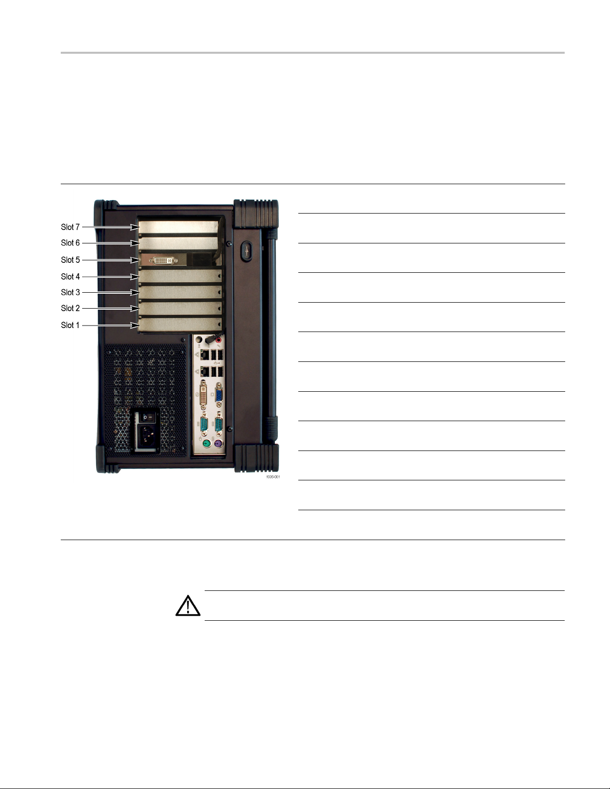
Install the interface card
Before install
ing any of the interface cards, refer to the following table and
illustration to determine which slots in the instrument you’ll be installing your
interface card or cards. Due to their size, some interface cards require two slots.
Table 2: Interface card slot locations
Interface
Instrument Slot Identification
1
Up to four optional interface cards can be installed into the instrument, but only two of the following options: S2, VS, QB2, IPTV.
Card
10GS
ASI
IPTV 6
QB2 2 & 3 COM3
S2 2 & 3 COM3
VS 2 & 3 COM3
IPTV
QB2
IPTV
VS
IPTV
S2
QB2
S2
QB2
VS
VS
S2
Slot
Location
1
4
6
2&3
6
2&3
6
2&3
6&7
2&3
6&7
2&3
6&7
2&3
CIP connection
on motherboard
N/A N/A
N/A N/A
COM3
COM3
COM4
COM3
COM4
COM3
COM4
COM3
COM4
COM3
COM4
COM3
COM4
CIP connection
on interface card
J10
J14
J14
J14
J10
J14
J10
J14
J10
J14
J14
J14
J14
J14
J14
J14
1. Power off the system and disconnect the power cord.
WAR NI NG . To avoid electric shock, verify the power cord is disconnected from the
instrument. Failure to do so can c ause injury or death.
2. Disconnect any cables from the rear panel. Note the location of any cables
for reinstallation.
MTS4000 Upgrade Kit Instructions 9
Page 22

Hardware upgrade instructions
3. Close front of t
with the rear panel facing up.
4. Unscrew the ei
out of the panel.)
he instrument and place the cabinet on the working surface
ght screws securing the rear panel. (The screws do not come
Figure 3: R emove rear panel
5. Lift the rear panel off the instrument. If necessary, disconnect the power
connector to the fan.
10 MTS4000 Upgrade K it Instructions
Page 23
Hardware upgrade instructions
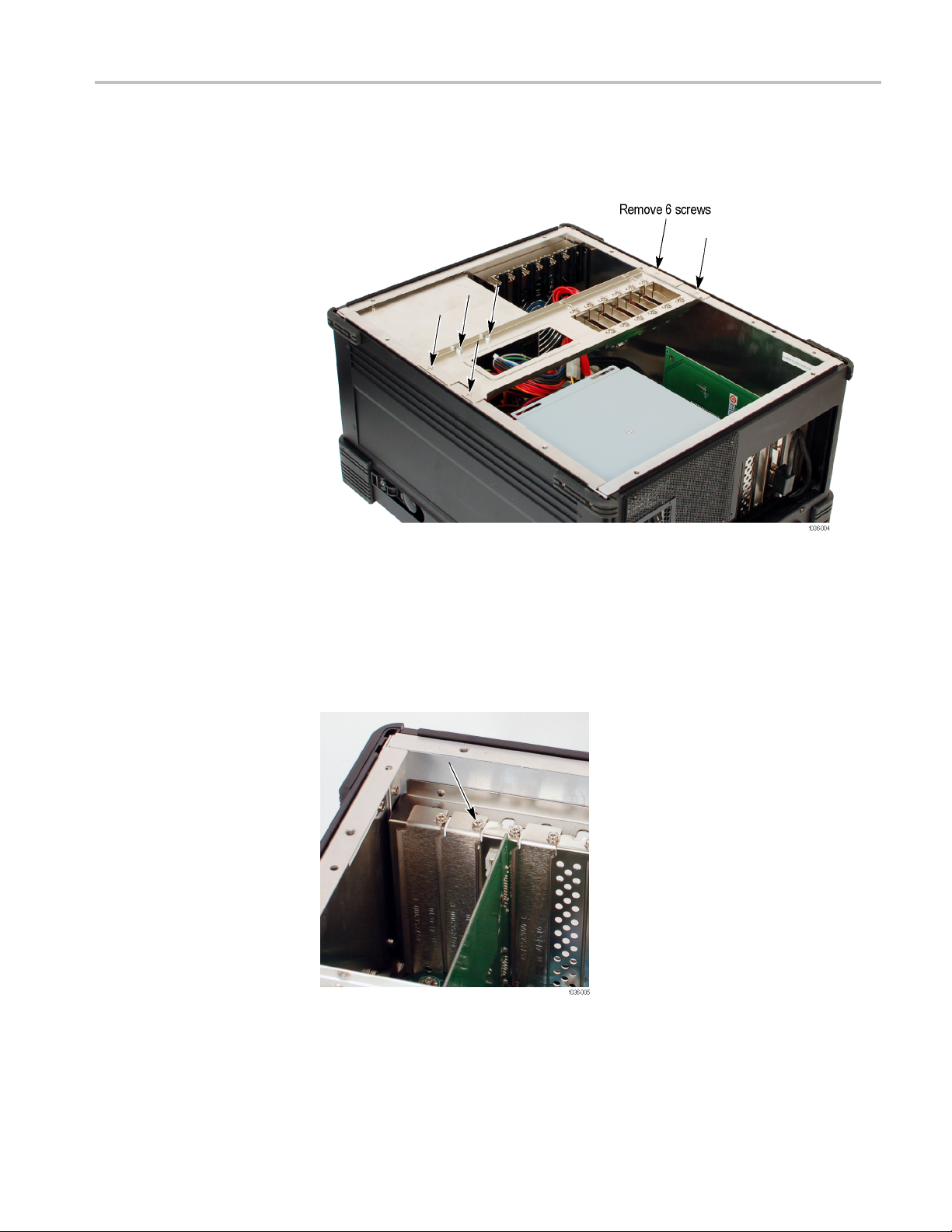
6. Remove the six s
from the cabinet.
7. Depending on the option card being installed, remove the appropriate
blank panel from the rear of the instrument. Use the table to identify the
mmended location for each of the available interface card. See the table
reco
Interface card slot locations.
crews from the interface card support bracket and lift it
nstalling multiple option cards, remove all appropriate blank panels at
If i
this time.
8. Install the interface card into the appropriate slot. Align the interface card
with the interface slot on the motherboard and the rear panel opening and
push the card into the interface slot.
MTS4000 Upgrade Kit Instructions 11
Page 24

Hardware upgrade instructions
9. Use the screw(s
card to the chassis.
NOTE. Some interface cards require the removal of two blank panels.
10. ASI Option only:
a. Install two
Torque the BNC nuts to 14 in/lb. with a 9/16" socket.
11. IPTV Optio
a. Install the CIP cable from J10 on the IPTV interface card to a COM
connecto
table at the beginning of this procedure to identify the proper placement of
the interface card and proper COM connector.
NOTE. The CIP cable must be installed so that the green wire on the CIP
cable connects to pin 1 on the option card. Pin 1 on the card is identified
with a triangle.
) from the removed blank panel(s) and attach the interface
BNC washers and a nut to each of the four BNC connectors.
n only:
r on the motherboard. Refer to the Interface card slot locations
Figure 4: CIP cable installation on option IPTV interface card
12 MTS4000 Upgrade K it Instructions
Page 25

Hardware upgrade instructions
Figure 5: COM connectors on motherboard
MTS4000 Upgrade Kit Instructions 13
Page 26

Hardware upgrade instructions
12. QB2, S2, and VS O
a. Install the CIP cable from J14 on the interface card to a COM connector
on the motherb
the beginning of this procedure to identify the proper placement of the
interface card and proper COM connector.
NOTE. The CIP cable must be installed so that the green wire on the CIP
cable connects to pin 1 on the option card. Pin 1 on the card is identified
with a triangle.
ptions only:
oard. Refer to the Interface card slot locations table at
Figure 6: CIP cable installation on option QB2, S2, and VS interface cards
14 MTS4000 Upgrade K it Instructions
Page 27

Hardware upgrade instructions
CAUTION. Before reinstalling the interface card support bracket in the next step,
check that non
13. Reinstall the interface card support bracket.
14. Some option cards are longer then others. If the option card being installed
reaches the adjustable card stabilizers on the interface card support bracket,
then you ne
a. Align the circuit board with the center of the pad on the stabilizer.
b. Slowly, lower the stabilizer by adjusting the two screws counterclockwise.
e of the card stabilizers are already in their lowered position.
ed to support the circuit board.
Adjust the screws a few turns at a time, alternating between the two
screws.
the interface card.
Continue lowering the stabilizer until the pad makes contact with
c. After the pad has made contact with the interface card, adjust the screws
tight enough so they don’t wobble.
NOTE. There should be two pads stacked together on the stabilizer. If not, use
one from an unused stabilizer.
MTS4000 Upgrade Kit Instructions 15
Page 28

Hardware upgrade instructions
15. Connect the power cable to the rear panel fan (if it was disconnected) and
install the rear panel.
16 MTS4000 Upgrade K it Instructions
Page 29

Optical SFP upgrades
Optical SFP up
grades
The Optical S
used with the Option IPTV interface card.
There are no
the Option IPTV interface card when required.
The Optica
MTS4KUP SX MTS4KUP LX MTS4KUP ZX
Figure 7: Sample SFP optical module
FP upgrade kits simply contain the new optical SFP module, to be
installation requirements other than installing the SFP module into
l SFP upgrade kits are:
MTS4000 Upgrade Kit Instructions 17
 Loading...