


Technical Reference
MTS400 Series
MPEG Test Systems
Specifications and Performance Verification
071-1724-04
This document applies to firmware version 1.4
and above.
Warning
The servicing instructions are for use by qualified
personnel only. To avoid personal injury, do not
perform any servicing unless you are qualified to
do so. Refer to all safety summaries prior to
performing service.
www.tektronix.com

Copyright Tektronix. All rights reserved. Licensed software products are owned by Tektronix or its subsidiaries or
suppliers, and are protected by national copyright laws and international treaty provisions.
Tektronix products are covered by U.S. and foreign patents, issued and pending. Information in this publication supercedes
that in all previously published material. Specifications and price change privileges reserved.
TEKTRONIX and TEK are registered trademarks of Tektronix, Inc.
Contacting Tektronix
Tektronix, Inc.
14200 SW Karl Braun Drive
P.O. Box 500
Beaverton, OR 97077
USA
For product information, sales, service, and technical support:
H In North America, call 1-800-833-9200.
H Worldwide, visit www.tektronix.com to find contacts in your area.

Table of Contents
General Safety Summary iii. . . . . . . . . . . . . . . . . . . . . . . . . . . . . . . . . . .
Service Safety Summary v. . . . . . . . . . . . . . . . . . . . . . . . . . . . . . . . . . . .
Preface vii. . . . . . . . . . . . . . . . . . . . . . . . . . . . . . . . . . . . . . . . . . . . . . . . . . .
Related Manuals vii. . . . . . . . . . . . . . . . . . . . . . . . . . . . . . . . . . . . . . . . . . . . . . . . .
Specifications
Electrical Specifications 1−2. . . . . . . . . . . . . . . . . . . . . . . . . . . . . . . . . . . . . . . . . . .
Mechanical Characteristics 1−19. . . . . . . . . . . . . . . . . . . . . . . . . . . . . . . . . . . . . . . .
Environmental Characteristics 1−20. . . . . . . . . . . . . . . . . . . . . . . . . . . . . . . . . . . . . .
Certifications and Compliances 1−21. . . . . . . . . . . . . . . . . . . . . . . . . . . . . . . . . . . . .
Performance Verification
Preparation 2−1. . . . . . . . . . . . . . . . . . . . . . . . . . . . . . . . . . . . . . . . . . . . . . . . . . . . .
Verification Procedures 2−3. . . . . . . . . . . . . . . . . . . . . . . . . . . . . . . . . . . . . . . . . . .
MTS400 Series MPEG Test Systems Technical Reference
i

Table of Contents
List of Figures
Figure 2−1: Cable connections on the MTS400 Series system 2−3. . . . . . . . . . . . .
Figure 2−2: Clock settings dialog box 2−4. . . . . . . . . . . . . . . . . . . . . . . . . . . . . . . .
Figure 2−3: PCR Initial Value settings dialog box 2−5. . . . . . . . . . . . . . . . . . . . . . .
Figure 2−4: Others settings dialog box and Select Update Item settings dialog box ...2−6
Figure 2−5: Stream Interpretation display in the Open Transport Stream window ... 2−7
Figure 2−6: Real Time Analysis display in the Open Transport Stream window ... 2−8
Figure 2−7: ASI interface analysis results 2−9. . . . . . . . . . . . . . . . . . . . . . . . . . . . .
Figure 2−8: Record Settings dialog box 2−10. . . . . . . . . . . . . . . . . . . . . . . . . . . . . . .
Figure 2−9: Record Settings window with the recording function armed 2−11. . . . .
Figure 2−10: MPEG Player playing a SMPTE310M transport stream 2−13. . . . . . .
Figure 2−11: SMPTE310M interface analysis results 2−14. . . . . . . . . . . . . . . . . . . .
Figure 2−12: SPI interface analysis results 2−16. . . . . . . . . . . . . . . . . . . . . . . . . . . .
Figure 2−13: RF interface selection 2−17. . . . . . . . . . . . . . . . . . . . . . . . . . . . . . . . . .
Figure 2−14: RF interface settings 2−18. . . . . . . . . . . . . . . . . . . . . . . . . . . . . . . . . . .
List of Tables
Table 1−1: Platform characteristics 1−2. . . . . . . . . . . . . . . . . . . . . . . . . . . . . . . . . .
Table 1−2: A11 and A12 Main MPEG I/O board electrical characteristics 1−4. . .
Table 1−3: A170 LVDS/ASI/SMPTE310M Interface board
electrical characteristics.. 1−6. . . . . . . . . . . . . . . . . . . . . . . . . . . . . . . . . . . . . .
Table 1−4: Baseband board electrical characterisics 1−8. . . . . . . . . . . . . . . . . . . .
Table 1−5: QPSK/8PSK interface board electrical characteristics
with a QPSK input 1−9. . . . . . . . . . . . . . . . . . . . . . . . . . . . . . . . . . . . . . . . . . . .
Table 1−6: QPSK/8PSK interface board electrical characteristics
with an 8PSK input 1−9. . . . . . . . . . . . . . . . . . . . . . . . . . . . . . . . . . . . . . . . . . .
Table 1−7: 8PSK and QPSK measurements 1−10. . . . . . . . . . . . . . . . . . . . . . . . . . .
Table 1−8: COFDM interface board electrical characteristics 1−11. . . . . . . . . . . . .
Table 1−9: COFDM measurements 1−12. . . . . . . . . . . . . . . . . . . . . . . . . . . . . . . . . .
Table 1−10: 8VSB board electrical characteristics 1−14. . . . . . . . . . . . . . . . . . . . . .
Table 1−11: 8VSB measurements 1−14. . . . . . . . . . . . . . . . . . . . . . . . . . . . . . . . . . .
Table 1−12: QAM Annex B board characteristics 1−15. . . . . . . . . . . . . . . . . . . . . .
Table 1−13: QAM Annex B measurements 1−16. . . . . . . . . . . . . . . . . . . . . . . . . . .
Table 1−14: Video over IP board - Ethernet Electrical Port 1−17. . . . . . . . . . . . . . .
Table 1−15: Video over IP board - Ethernet Optical port 1−17. . . . . . . . . . . . . . . . .
Table 1−16: AC power source electrical characteristics 1−18. . . . . . . . . . . . . . . . . .
Table 1−17: Mechanical characteristics 1−19. . . . . . . . . . . . . . . . . . . . . . . . . . . . . .
Table 1−18: Environmental characteristics 1−20. . . . . . . . . . . . . . . . . . . . . . . . . . . .
Table 1−19: Certifications and compliances 1−21. . . . . . . . . . . . . . . . . . . . . . . . . . .
ii
MTS400 Series MPEG Test Systems Technical Reference

General Safety Summary
Review the following safety precautions to avoid injury and prevent damage to
this product or any products connected to it.
To avoid potential hazards, use this product only as specified.
Only qualified personnel should perform service procedures.
While using this product, you may need to access other parts of the system. Read
the General Safety Summary in other system manuals for warnings and cautions
related to operating the system.
To Avoid Fire or
Personal Injury
Use Proper Power Cord. Use only the power cord specified for this product and
certified for the country of use.
Connect and Disconnect Properly. Do not connect or disconnect probes or test
leads while they are connected to a voltage source.
Ground the Product. This product is grounded through the grounding conductor
of the power cord. To avoid electric shock, the grounding conductor must be
connected to earth ground. Before making connections to the input or output
terminals of the product, ensure that the product is properly grounded.
Observe All Terminal Ratings. To avoid fire or shock hazard, observe all ratings
and markings on the product. Consult the product manual for further ratings
information before making connections to the product.
Do not apply a potential to any terminal, including the common terminal, that
exceeds the maximum rating of that terminal.
Powering Off. The power cord provides Mains disconnect.
Replace Batteries Properly. Replace batteries only with the proper type and rating
specified.
Do Not Operate Without Covers. Do not operate this product with covers or panels
removed.
Use Proper Fuse. Use only the fuse type and rating specified for this product.
Avoid Exposed Circuitry. Do not touch exposed connections and components
when power is present.
Wear Eye Protection. Wear eye protection if exposure to high-intensity rays or
laser radiation exists.
Do Not Operate With Suspected Failures. If you suspect there is damage to this
product, have it inspected by qualified service personnel.
Do Not Operate in Wet/Damp Conditions.
MTS400 Series MPEG Test Systems Technical Reference
iii

General Safety Summary
Do Not Operate in an Explosive Atmosphere.
Keep Product Surfaces Clean and Dry.
Provide Proper Ventilation. Refer to the manual’s installation instructions for
details on installing the product so it has proper ventilation.
Symbols and Terms
Terms in this Manual. These terms may appear in this manual:
WARNING. Warning statements identify conditions or practices that could result
in injury or loss of life.
CAUTION. Caution statements identify conditions or practices that could result in
damage to this product or other property.
Terms on the Product. These terms may appear on the product:
DANGER indicates an injury hazard immediately accessible as you read the
marking.
WARNING indicates an injury hazard not immediately accessible as you read the
marking.
CAUTION indicates a hazard to property including the product.
Symbols on the Product. The following symbols may appear on the product:
iv
CAUTION
Refer to Manual
WARNING
High Voltage
Protective Ground
(Earth) Terminal
Standby
MTS400 Series MPEG Test Systems Technical Reference

Service Safety Summary
Only qualified personnel should perform service procedures. Read this Service
Safety Summary and the General Safety Summary before performing any service
procedures.
Do Not Service Alone. Do not perform internal service or adjustments of this
product unless another person capable of rendering first aid and resuscitation is
present.
Disconnect Power. To avoid electric shock, switch off the instrument power, then
disconnect the power cord from the mains power.
Use Care When Servicing With Power On. Dangerous voltages or currents may
exist in this product. Disconnect power, remove battery (if applicable), and
disconnect test leads before removing protective panels, soldering, or replacing
components.
To avoid electric shock, do not touch exposed connections.
MTS400 Series MPEG Test Systems Technical Reference
v

Service Safety Summary
vi
MTS400 Series MPEG Test Systems Technical Reference

Preface
Related Manuals
This manual lists the electrical, mechanical, and environmental specifications,
and the certification and compliance statements for the Tektronix MTS400 Series
MPEG Test Systems instruments. Also provided are procedures for verifying the
performance of the instrument.
NOTE. Text in this manual about the MPEG Player refers to the MPEG player
application installed in the MTS400 Series systems (MTS400, and MTS430).
The MTX100B MPEG Player and Recorder is described in the MTX100B user
documentation.
The following manuals are also available to use with the MTS400 Series MPEG
Test Systems. These manuals are shipped with each system, and are also
available on the Tektronix Web site.
H MTS400 Series MPEG Test Systems Getting Started Manual (Tektronix part
numbers: 071-1505-xx, English; 071-1727-xx, Japanese). This manual
describes the functions and use of the instrument, and provides software
recovery and network troubleshooting information.
H MTS400 Series MPEG Test Systems User Manual (Tektronix part number
071-1507-xx). This manual provides in-depth operating information for the
software applications included in the MTS400 Series system.
H MTS400 Series MPEG Test Systems Programmers Manual (Tektronix part
number 071-1725-xx). This manual describes the remote control commands
available for the MPEG Player application.
H MTS400 Series MPEG Test Systems Release Notes (Tektronix part number
071-1726-xx). This manual provides information about software problems
and behaviors.
MTS400 Series MPEG Test Systems Technical Reference
vii

Preface
viii
MTS400 Series MPEG Test Systems Technical Reference

Specifications
This chapter contains specifications for the MTS400 Series MPEG Test Systems.
All specifications are guaranteed unless labeled “typical.” Typical specifications
are provided for your convenience but are not guaranteed.
Unless otherwise stated, all specifications apply to both the MTS400 and
MTS430 MPEG Test Systems.
To meet specifications, the following conditions must be met:
H The system must have been calibrated/adjusted in an ambient temperature
between 20 °C and 30 °C (68 °F and 86 °F).
H The system must be kept within the environmental limits specified in this
document.
H The system must be powered from a source maintaining voltage and
frequency within the limits described in this document.
H The system must have been operating continuously for at least 20 minutes
within the specified operating temperature range.
H The instrument must have had its signal-path-compensation routine last
executed after at least a 20 minute warm-up period at an ambient temperature
within 5 °C of the current ambient temperature.
Any conditions that are unique to a particular characteristic are expressly stated
as part of that characteristic.
NOTE. The product calibration classification for this system is List 2; no
calibration data reports are available. However, all measurement equipment
used to establish or verify conformance of the product with published specifications is traceable.
MTS400 Series MPEG Test Systems Technical Reference
1−1

Specifications
Electrical Specifications
The following tables list the published specifications for the MTS400 Series
MPEG Test Systems.
Platform Characteristics
Table 1−1 lists the general characteristics of the MTS400 Series platform.
Table 1−1: Platform characteristics
Characteristic Description
Operating system Microsoft Windows XP Professional with
Service Pack 2
Processor P4, 2.8 GHz
Disk space
Operating system and software applications 82 GB, Ultra ATA100 IDE hard drive
MPEG file storage 144 GB total (two, 72 GB SCSI hard drives,
one for Playout and one for Record)
MPEG storage disk I/O port SCSI-3 (Ultra 160), Micro D68 connector,
68 pin
RAM 1 GB (one SIM of DDRS memory)
CD-ROM drive CD−R/W, DVD−R/RW, DVD+R/RW
Floppy disk drive 3.5 inch, 1.44 MB high density, double-sided
(2HD)
Display LCD, 1024 X 768, 10.4 inch
Ethernet
10/100 One 10/100Base-T; RJ45 connector
1−2
Supported protocol: Ethernet/IP/UDP/
MPEG-TS and VLAN
When used in MPEG-TS protocol, the
minimum and maximum link bit rates are
250 kbps and 100 Mbps respectively
IP playout bit rate is typically up to 90 Mbps
10/100/1000 (GigE) One 10/100/1000Base-T; RJ45 connector
Supported protocol: Ethernet/IP/UDP/
MPEG-TS and VLAN
When used in MPEG-TS analysis and
record, the minimum and maximum link bit
rates are typically 250 kbps and 100 Mbps
respectively
IP playout bit rate is typically up to
190 Mbps
MTS400 Series MPEG Test Systems Technical Reference

Specifications
Table 1−1: Platform characteristics (Cont.)
Characteristic Description
Keyboard port Mini DIN, PS-2, one on the rear panel and
one on the left front side panel; not hot
pluggable
Mouse port Mini DIN, PS-2; one on the rear panel and
one on the left front side panel; not hot
pluggable
Printer port IEEE P1284. Bidirectional parallel commu-
nications port
External VGA Output 15-pin, high density, Sub-D; resolution
needs to be set to the same as the integral
LCD display, 1024 x 768
COM port RS-232
USB port USB device connector
MTS400 Series MPEG Test Systems Technical Reference
1−3

Specifications
A11 and A12 Main MPEG
I/O Board Characteristics
The electrical characteristics listed in Table 1−2 apply to both the A11 and A12
Main MPEG I/O boards.
Table 1−2: A11 and A12 Main MPEG I/O board electrical characteristics
Characteristic Description
Internal reference clock, typical 27 MHz "1 ppm
This clock is used for the following functions:
output clock, PCR/PTS/DTS timing, packet
operation timing, and TDT/STT timing
External reference / clock input
Input connector type BNC, 50 , AC coupled
Frequency
External reference input 8.12698 MHz, 10 MHz, 27 MHz
External clock input 160 kHz to 25 MHz (parallel clock)
1.28 MHz to 32 MHz (serial clock)
Amplitude
External reference input, typical 0 "6 dBm (peak-to-peak, sine wave)
0.5 V to 3.0 V (square wave)
External clock input, typical 0.5 V to 3.0 V (square wave)
External TTL trigger input
Input connector type BNC, 1 k
Threshold level
High level >3.5 V (maximum voltage limit is 7.0 V)
Low level <0.8 V
PPL
Frequency range 64 MHz to 128 MHz
Output clock
Maximum rate 64 MHz (serial clock)
25 MHz (parallel clock)
Internal and external 27 MHz Output clock = (X / (2 * Y * Z)) * 27 MHz
512 < X < 131071, 3400 < Y < 6000, 2 <= Z
<= 65536 (second power)
1−4
External parallel clock Output clock = 108 MHz * Y / X,
512 < X < 131071, 8 < Y < 16383
External serial clock Output clock = 864 MHz * Y / X,
512 < X < 131071, 8 < Y < 16383
Output data rate 250 kbps minimum,
214 Mbps maximum
P/N and jitter (serial clock) <−104 dBc/Hz, RBW = 300 Hz, @21.455707 MHz
+ 20 kHz
MTS400 Series MPEG Test Systems Technical Reference

Specifications
Table 1−2: A11 and A12 Main MPEG I/O board electrical characteristics (Cont.)
Characteristic Description
DVB−SPI Interface
Input/output configuration Output only
Connector type D-sub, 25-pin
Data rate 250 kbps to 108 Mbps (107 Mbps maximum in
duplex mode)
Pin assignment 1 DCLK
2 Ground
3 to 10 DATA 7 to DATA 0
11 DVALID
12 PSYNC
13 Shield
14 /DCLK
15 Ground
16 to 23 /DATA 7 to DATA 0
24 /DVALID
25 /PSYNC
Output amplitude, typical 240 mV to 550 mV (BUS LVDS with 100
termination)
Output offset 1.1 V to 1.5 V
Output impedance 100 , between differential outputs with output off
Data delay "5 ns from DCLK falling edge
Input level >200 mVpp, (RI+)−(RI−) with 100 termination
Data hold time T/2 "T/10, T=1/f, data latch on DCLK rising edge
MTS400 Series MPEG Test Systems Technical Reference
1−5

Specifications
A170
LVDS/ASI/SMPTE310M
Interface Board
Table 1−3 lists the electrical characteristics of the A170 LVDS/ASI/
SMPTE310M Interface board.
Table 1−3: A170 LVDS/ASI/SMPTE310M Interface board electrical
characteristics
Characteristic Description
Internal reference clock, typical 27 MHz "1 ppm
ASI interface
Connector type BNC (common connector with SMPTE310M
interface)
Bit rate 250 kbps to 213 Mbps (107 Mbps maximum in
duplex mode)
Output
Output impedance 75 transformer coupled
Voltage 800 mV "10% into 75 load
Jitter v0.2 UI
Maximum rise/fall time v1.2 ns, 20% to 80%
Return loss, typical >17 dB (5 MHz to 270 MHz) into 75 load
Transmission format Packet mode or Burst mode
Input
Input impedance 75 transformer coupled
Voltage 200 mV to 880 mV (maximum limit: 3 Vpp @AC,
15 mA @DC)
Data format Accepts both Packet mode and Burst mode ASI
signals
Return loss, typical >17 dB (5 MHz to 270 MHz) into 75 load
SMPTE310M interface
Connector type BNC (common connector with ASI interface)
Bit rate 19,392,658.5 bps
Output
Output impedance 75 transformer coupled
Voltage 800 mV "10% into 75 load
Jitter, typical <2 ns p-p logic 0 rising edge when triggered on
negative edge (EN50083-9.1998 Figure A.4)
1−6
<1.4 ns p-p logic 1 rising edge when triggered on
negative edge (EN50083-9.1998 Figure A.5)
Rise/fall time 0.4 ns v X v 5 ns, 20% to 80%
Return loss, typical >30 dB (5 MHz to 38.785316 MHz) into 75 load
MTS400 Series MPEG Test Systems Technical Reference

Table 1−3: A170 LVDS/ASI/SMPTE310M Interface board electrical
characteristics (Cont.)
Characteristic Description
SMPTE310M interface (cont.)
Input
Input impedance 75 transformer coupled
Voltage 200 mV to 880 mV (maximum limit: 3 Vpp @AC,
15 mA @DC)
Data format Bi-phase coded, compliant with SMPTE310M
Input bit rate 19,392,658.5 bps
Return loss, typical >17 dB (5 MHz to 38.785316 MHz) into 75 load
DVB−SPI interface
Input/output configuration Input only
Connector type D-sub, 25-pin
Data rate 250 kbps to 108 Mbps (107 Mbps maximum in
duplex mode)
Pin assignment 1 DCLK
2 Ground
3 to 10 DATA 7 to DATA 0
11 DVALID
12 PSYNC
13 Shield
14 /DCLK
15 Ground
16 to 23 /DATA 7 to DATA 0
24 /DVALID
25 /PSYNC
Specifications
Data delay "5 ns from DCLK falling edge
Input level >200 mVpp, (RI+)−(RI−) with 100 termination
Input impedance 100 , between differential inputs
Clock pulse width T/2 "T/10, T=1/f (f = byte clock frequency)
Data hold time T/2 "T/10, T=1/f, data latch on DCLK rising edge
MTS400 Series MPEG Test Systems Technical Reference
1−7

Specifications
Baseband Board
Characteristics
Table 1−4 lists the electrical characteristics of the MTM400 Baseband board.
Table 1−4: Baseband board electrical characterisics
Characteristic Description
ASI interface
Connector type BNC (common connector with SMPTE310M
interface)
Bit rate 250 kbps to 155 Mbps
ASI Input Accepts both Burst mode and Packet mode ASI
format
Signal amplitude 2.0 V peak-to-peak, maximum
Input impedance 75 transformer coupled
Return loss, typical 10 dB minimum, 5 MHz to 270 MHz
Link rate, typical 270 Mbaud "100 ppm
ASI Output
Signal amplitude 1.0 V peak-to-peak, maximum
600 mV peak-to-peak, minimum
into 75 load
Output impedance 75 transformer coupled
Return loss, typical 10 dB @ 270 MHz
SMPTE310M interface
Connector type BNC
Bit rate 19,392,658.5 bps "2.8 ppm
SMPTE Input
Input impedance 75 transformer coupled
Data format Bi−phase coded, compliant with SMPTE310M
Signal amplitude 2.0 V peak-to-peak, maximum
200 mV peak-to-peak minimum
Return loss, typical 10 dB minimum @ 20 MHz
SMPTE Output
Signal amplitude 600 mV minimum, 1.0 V maximum
into 75 load
Output impedance 75 transformer coupled
Return loss, typical 10 dB minimum @ 20 MHz
1−8
MTS400 Series MPEG Test Systems Technical Reference

Specifications
QPSK/8PSK Board
Characteristics
Tables 1−5 and 1−6 list electrical characteristics of the QPSK/8PSK board.
Table 1−5: QPSK/8PSK interface board electrical characteristics with a QPSK
input
Characteristic Description
Input frequency range 950 MHz to 2150 MHz with 1 MHz step size
Input signal amplitude range −60 dBm to −30 dBm for a CBER of <1e
Modulation format QPSK in accordance with ETSI EN 300 421
Modulated baud rate 1 MBaud min, 30 MBaud max
Viterbi values supported 1/2, 2/3, 3/4, 5/6, 6/7, 7/8
FEC In accordance with ETSI EN 300 421
Turbo viterbi values supported 1/2, 2/3, 3/4, 5/6, 7/8
Turbo FEC Turbo code
Connector style F-style
Input termination impedance 75 nominal
Input return loss 4 dB min, 950 MHz to 2050 MHz
LNB supply voltage Selectable; 13.0 V "1.5 V or 18.0 V "1.5 V, with
100 , 5 watt resistor load
LNB supply maximum current 200 mA maximum
LNB 22 kHz signaling frequency 17.6 kHz min, 26.4 kHz max (22 kHz "20%)
LNB 22 kHz signaling amplitude 600 mV p-p with a 100 load
Ultimate modulation error ratio (with
equalizer)
26 dB with an equalizer
−6
Table 1−6: QPSK/8PSK interface board electrical characteristics with an 8PSK
input
Characteristic Description
Input frequency range 950 MHz to 2150 MHz with 1 MHz step size
Input signal amplitude range −60 dBm to −30 dBm for a CBER of <1e
Modulation format Turbo 8PSK
Modulated baud rate 1 MBaud min, 30 MBaud max
Turbo viterbi values supported 2/3, 3/4 (2.05), 3/4 (2.1), 5/6, 8/9
Turbo FEC Turbo code
Connector style F-style
Input termination impedance 75 nominal
MTS400 Series MPEG Test Systems Technical Reference
−6
1−9

Specifications
Table 1−6: QPSK/8PSK interface board electrical characteristics with an 8PSK
input (Cont.)
Characteristic Description
Input return loss 4 dB min, 950 MHz to 2050 MHz
LNB supply voltage Selectable; 13.0 V "1.5 V or 18.0 V "1.5 V, with
100 , 5 watt resistor load
LNB supply maximum current 200 mA maximum
LNB 22 kHz signaling frequency 17.6 kHz min, 26.4 kHz max (22 kHz "20%)
LNB 22 kHz signaling amplitude 600 mV p-p with a 100 load
Ultimate modulation error ratio (with
equalizer)
26 dB with an equalizer
8PSK and QPSK
Measurements
Table 1−7 lists electrical characteristics for 8PSK and QPSK measurements.
Table 1−7: 8PSK and QPSK measurements
Characteristic Description
RF lock RF lock is indicated by LED and Status
Input level (signal strength) Range: −60 dBm to −30 dBm
Resolution: 1 dBm
Accuracy: "5 dBm
EVM (Error Vector Magnitude) Display Range: v 4.0% to w 30.0% rms
Resolution: 0.1%
Accuracy: "20% of reading
MER (Modulation Error Ratio) with an
equalizer
SNR (Signal-to-Noise Ratio) Display Range: 5 dB to 35 dB
Pre Reed Solomon (RS) BER (Bit Error
Rate)
Post RS BER and TEF (Transport Error
Flag)
Display Range: 10 dB to 26 dB with an equalizer
Resolution: 1 dB
Accuracy: "2 dB for range 10 dB to 20 dB
Resolution: 1 dB
Accuracy: "2 dB for range from 5 dB to 30 dB
Pre-RS BER is displayed
Post Reed Solomon BER (TEF ratio), TEF rate, and
number of Transport Error Flags (TEF count) are
displayed
1−10
Constellation RF constellation is displayed
MTS400 Series MPEG Test Systems Technical Reference

Specifications
COFDM Board
Characteristics
Table 1−8 lists electrical characteristics for the COFDM interface board.
Table 1−8: COFDM interface board electrical characteristics
Characteristic Description
Input frequency range 50 MHz to 858 MHz (to include low VHF)
Input signal amplitude range The receiver delivers QEF (Quasi Error Free)
operation over the following signal power ranges:
QPSK (4QAM): −85 dBm to −15 dBm (24 dBuV to
94 dBuV)
16QAM: −80 dBm to −15 dBm (29 dBuV to 94 dBuV)
64QAM: −72 dBm to −15 dBm (37 dBuV to 94 dBuV)
QEF operation is equivalent to a post Viterbi BER of
2x10⁻⁴ or better
w −50 dBm to ensure compliance to IEC 61000-4-3
immunity
Compliance COFDM (DVB-T) receptions and demodulation are
compliant with ETSI EN300-744, 2 K, and 8 K
transmission modes
Tuning resolution 166.7 kHz or smaller increments
Tuning accuracy Better than "50 ppm
Channel bandwidth 7 MHz and 8 MHz (software selectable)
Connector style F-style
Input termination impedance 75 nominal
Input return loss 7 dB minimum, 50 MHz to 858 MHz
Modulation schemes supported QPSK (4QAM), 16QAM, and 64QAM modulation
Transmission modes 2 K carriers, and 8 K carriers
Hierarchical modulation All hierarchies will be supported, to include no
hierarchy, and alpha = 1, 2 and 4.
Viterbi puncture rates 1/2, 2/3, 3/4, 5/6, 7/8
Guard intervals 1/32, 1/16, 1/8, 1/4
Spectrum polarity The receiver will operate with both inverted and
normal spectral polarity
Ultimate modulation error ratio, with
equalizer
w 37 dB with an equalizer
MTS400 Series MPEG Test Systems Technical Reference
1−11

Specifications
COFDM Board
Measurements
Table 1−9 lists the electrical characteristics for the COFDM measurements.
Table 1−9: COFDM measurements
Characteristic Description
Overall receiver lock status Overall receiver lock status is indicated by an LED on
the rear panel
Transmission coding parameters The receiver reports the current status of the
following transmission parameters:
− QPSK/16, QAM/64, QAM encoding
− 2K/8K Transmission mode
− Hierarchy status (hierarchy on/off, alpha value)
− Viterbi puncture rate
− Guard Interval Value
− Gross bit rate in the channel
− Spectrum polarity (inverted/non-inverted)
Input level (signal strength) Ranges, High Sensitivity mode:
QPSK (4QAM): −85 dBm to −10 dBm (24 dBuV to
99 dBuV)
16QAM: −80 dBm to −10 dBm (29 dBuV to
99 dBuV)
64QAM: −72 dBm to −13 dBm (37 dBuV to
96 dBuV)
Ranges, High Resolution mode:
QPSK (4QAM): −45 dBm to −10 dBm (64 dBuV to
99 dBuV)
16QAM: −45 dBm to −10 dBm (64 dBuV to
99 dBuV)
64QAM: −45 dBm to −13 dBm (64 dBuV to
96 dBuV)
Resolution: 1 dBm
Accuracy: "3 dBm
RF carrier offset Accuracy: "50 ppm of the tuned frequency
SNR (Signal to Noise Ratio) Display Range:
6 dB to 40 dB for QPSK (4QAM)
11 dB to 40 dB for 16QAM
16 dB to 40 dB for 64QAM
Resolution: 1 dB
Accuracy: "1 dB to 30 dB SNR (measured at
−30 dBm input in high resolution mode)
1−12
MTS400 Series MPEG Test Systems Technical Reference

Table 1−9: COFDM measurements (Cont.)
Characteristic Description
EVM (Error Vector Magnitude) Display Range:
v 1% to w 30% rms, for QPSK
v 1% to w 20% rms, 16QAM
v 1% to w 8.5% rms, 64QAM
Resolution: 0.1%
Accuracy: 1% (1 EVM unit), and an additional "20%
of the reading
Specifications
MER (Modulation Error Ratio) with an
equalizer
Carrier power distribution Carrier-by-carrier signal-to-noise power ratio is
Channel equalization status Channel estimate I and Q values for each carrier are
Constellation The RF constellation is displayed
BER Pre-Viterbi BER and Pre Reed-Solomon BER values
Post RS BER and TEF (Transport Error
Flag)
Both MER Peak and MER Average are displayed as
measured across all carriers
Display Range:
6 dB to 37 dB for QPSK (4QAM)
11 dB to 37 dB for 16QAM
16 dB to 37 dB for 64QAM
Resolution: 0.1 dB
Accuracy: "1 dB to 30 dB (Measured at −30 dBm
input in High Resolution mode). For best MER
accuracy, use High Resolution mode, and maintain
the input signal level between −45 dBm and
−15 dBm
displayed
Channel Flatness in dB can be viewed from the
spectrum display
Tilt in dB can be viewed from the spectrum display
displayed
are displayed
Post Reed Solomon BER (uncorrectable error count)
and number of Transport Error Flags are displayed
MTS400 Series MPEG Test Systems Technical Reference
1−13

Specifications
8VSB Board
Characteristics
8VSB Measurements
Table 1−10 lists the electrical characteristics for the 8VSB board.
Table 1−10: 8VSB board electrical characteristics
Characteristic Description
Input frequency range 54 MHz to 860 MHz, VHF/UHF channels 2 to 69 (to
include low VHF frequencies)
Input signal level −72 dBm to −6 dBm (−23 dBmV to )43 dBmV)
w −50 dBm to ensure compliance to IEC 61000-4-3
immunity
Modulation format 8VSB in accordance with ATSC A/53B
Receiver bandwidth 6 MHz
Input termination impedance 75 nominal
Connector type F-type
Input return loss 5 dB minimum
Ultimate equivalent MER, with an
equalizer
w 31 dB with an equalizer
Table 1−11 lists the electrical characteristics for the 8VSB measurements.
Table 1−11: 8VSB measurements
Characteristic Description
RF Lock RF lock is indicated by LED and Status
Input level (signal strength) Display Range:
−72 dBm to −2 dBm relative to 75 (−23 dBmV to
+47 dBmV)
Resolution: 1dB
Accuracy:"3dB
EVM (Error Vector Magnitude) Display Range: v3.0% to w12.5% rms
Resolution: 0.1%
Accuracy:"20% of reading
Equivalent MER (Modulation Error
Ratio) with Equalizer
SNR (Signal to Noise Ratio) Display Range: 15 dB to 35 dB
Display Range: 17 dB to 31 dB with Equalizer
Resolution: 0.1 dB
Accuracy: "1 dB for MER u25 dB;
"3 db for MER 25 dB to 31 dB
(Measured at −30 dBm input. For best MER
accuracy, maintain the input signal level between
−50 dBm and −15 dBm.)
Resolution: 1 dB
Accuracy: "1 dB for SNR < 25 dB;
"3 db for SNR 25 dB to 35 dB
1−14
MTS400 Series MPEG Test Systems Technical Reference

Specifications
Table 1−11: 8VSB measurements (Cont.)
Characteristic Description
BER Pre-RS BER, SER 1 second and 10 seconds
windows values are displayed
TEF (Transport Error Flag) Transport Error Flags (uncorrectable error count) in a
1 second window and 10 second window are
displayed
Constellation diagram The 8VSB constellation diagram is a display of I-data
history with histograms (the IQ constellation is not
available). This is displayed as Symbol Distribution in
the user interface
Echo profile Equalizer filter tap information is displayed.
Display Echo Level range: Normalized real tap
values over the range of −1 to 1
Display Delay range: −6.7 μs to 45.5 μs
QAM Annex B Board
Characteristics
Table 1−12 lists electrical characteristics for the QAM Annex B board.
Table 1−12: QAM Annex B board characteristics
Characteristic Description
Input frequency range 88 MHz to 858 MHz
Input signal level −64 dBm to −19 dBm (45 dBuV to 90 dBuV relative
to 75 )
With either a 64 or 256 QAM input, there are five or
fewer Transport Error Flags in 11 seconds, which
corresponds to a post FEC rate of 1e
w-40 dBm when operated in an electromagnetic
field of 3 V/m or more
Modulation format 64QAM, 256QAM (compliant with ITU J-83
Annex B)
Interleaving mode Level 1 and Level 2 interleaving support compliant
with all ITU J-83 Annex B, excluding I, J = (128,7)
and (128,8), and in 256 QAM excluding (8, 16) and
(16, 8)
Modulation baud rate 64 QAM: 5.056941 Mbaud/s
256 QAM: 5.360537 Mbaud/s
Spectrum polarity Demodulates both Normal and Inverted IF Spectrum
Receiver bandwidth, QAM B 6 MHz nominal
Connector type F type
Input termination impedance 75 nominal
−8
MTS400 Series MPEG Test Systems Technical Reference
1−15

Specifications
Table 1−12: QAM Annex B board characteristics (Cont.)
Characteristic Description
Input return loss 5 dB minimum
Ultimate Modulation Error Ratio with
equalizer
w37 dB with an equalizer
QAM Annex B Board
Characteristics
Table 1−13 lists electrical characteristics for the QAM Annex B measurements.
Table 1−13: QAM Annex B measurements
Characteristic Description
RF lock RF lock is indicated by LED and Status
Input level (signal strength) Range: −64 dBm to −19 dBm (45 dBuV to 90 dBuV
relative to 75 )
Resolution: 1 dB
Accuracy: "3 dB
EVM (Error Vector Magnitude) Display Range for 64 QAM: v1% to w5% rms
Display Range for 256 QAM: v1% to w2.5% rms
Resolution: 0.1%
Accuracy: "1%
MER (Modulation Error Ratio) with
Equalizer
SNR (Signal to Noise Ratio) Display Range:
BER (Bit Error Ratio) Pre-RS BER is displayed
TEF (Transport Error Flag) Transport Error Flags (uncorrectable error count) in a
Display Range:
64 QAM: 22 dB to 37 dB
256 QAM: 28 dB to 37 dB
Resolution: 0.1 dB
Accuracy: "1 dB for MER < 25 dB; "3 db for MER
25 dB to 34 dB (measured at −30 dBm input)
64QAM: 22 dB to 37 dB
256QAM: 28 dB to 37 dB
Resolution: 1 dB
Accuracy: "1 dB for SNR < 25 dB; "3 db for SNR
25 dB to 34 dB
1 second window and 10 second window are
displayed
1−16
Constellation The RF constellation is displayed
MTS400 Series MPEG Test Systems Technical Reference

Specifications
Video Over IP Electrical
Characteristics
Video Over IP Optical
Characteristics
Table 1−14 lists the general and electrical characteristics for the Video Over IP
board.
Table 1−14: Video Over IP board - Ethernet Electrical Port
Characteristic Description
Standard 10/100/1000BASE-T IEEE 802.3
Connector type RJ-45
Data Format 10/100 Base T NRZ
Data Format 1000 Base T Trellis encoded, PAM5 symbols, full-duplex on 4-pair Cat-5
UTP per IEEE 802.3ab
Table 1−15 lists the general and optical characteristics for the Video Over IP
board.
Table 1−15: Video Over IP board - Ethernet Optical port
Characteristic Description
Ethernet Optical Transmitter - General Characteristics
Optical operating mode
Connector type Duplex data link MSA compliant SFP connector
Standard 1000 BASE-X
Data format NRZ
Ethernet Optical Transmitter - Single mode 1550 nm using Tektronix supplied SFP
module
Output power −2 dBm to +4 dBm
Center wavelength - 1550 nm 1530 nm Min, 1550 nm typical, 1570 nm max
Total jitter (peak-to-peak) t170 ps
Extinction ratio w9.0 dBm
Ethernet Optical Receiver - Single mode 1550 nm using Tektronix supplied SFP module
Optical input power −26 dBm to −3 dBm, BER 1 X 10
Input wavelength 1270 nm = λ = 1610 nm
Single mode or Multimode
−12
MTS400 Series MPEG Test Systems Technical Reference
1−17

Specifications
Table 1−15: Video Over IP board - Ethernet Optical port (Cont.)
Characteristic Description
Ethernet Optical Transmitter - Single mode 1310 nm using Tektronix supplied SFP
module
Output power −11 dBm to −3 dBm
Center wavelength - 1310 nm 1270 nm Min, 1310 nm typical, 1355 nm max
Total jitter (peak-to-peak) t170 ps
Extinction ratio w9.0 dBm
Ethernet Optical Receiver - Single mode 1310 nm using Tektronix supplied SFP module
Optical input power −19 dBm to −3 dBm, BER 1 X 10
Input wavelength 1270 nm = λ = 1610 nm
Ethernet Optical Transmitter - Multimode 850 nm using Tektronix supplied SFP module
Output power −9.5 dBm to −2 dBm
Center wavelength - 850 nm 830 nm Min, 850 nm typical, 860 nm Ma
Total jitter (peak-to-peak) t170 ps
Extinction ratio w9.0 dBm
Ethernet Optical Receiver - Multimode 850 nm using Tektronix supplied SFP module
Optical input power −17 dBm to 0 dBm, BER 1 X 10
Input wavelength 770 nm = λ = 860 nm
−12
−12
1−18
AC Power Source
Characteristics
Table 1−16 lists the electrical characteristics of the AC power source.
Table 1−16: AC power source electrical characteristics
Characteristic Description
Source voltage 100 to 240 VAC "10% (90 to 264 VAC RMS)
Frequency range 50/60 Hz
Power consumption 4 A maximum (marked on rear panel)
Peak inrush current 13 A peak at 240 VAC, 50 Hz
Mains fuse value T6.3AH, 250 V, Fast; not operator replaceable.
Refer servicing to qualified service personnel
MTS400 Series MPEG Test Systems Technical Reference

Mechanical Characteristics
Table 1−17 lists the mechanical characteristics of the MTS400 Series platform.
Table 1−17: Mechanical characteristics
Characteristic Description
Classification Fixed location benchtop
Cooling airflow Intake is from the front and sides of the instrument.
Overall dimensions Height 226 mm (8.9 in), without bottom feet
Weight 17.7 kg (39 lb)
Shipping weight 27.3 kg (64.5 lb)
Specifications
Exhaust is to the bottom and rear of the instrument
For proper cooling, at least two inches (5.1 cm) of
clearance is needed on the rear and sides of the
instrument cabinet
Width: 432 mm (17 in)
Depth: 560 mm (22 in), with rear feet
MTS400 Series MPEG Test Systems Technical Reference
1−19

Specifications
Environmental Characteristics
Table 1−18 lists the environmental characteristics of the MTS400 Series
platform.
Table 1−18: Environmental characteristics
Characteristic Description
Atmospherics
Temperature
Operating +5 °C to +40 °C, 30 °C per hour maximum
Non-operating −20 °C to +60 °C, 30 °C per hour maximum
Humidity
Operating 20% to 80% relative humidity up to 29 °C.
Non-operating 10% to 80% relative humidity, non-condensing
Altitude
Operating 0 to 3000 m (9800 ft)
Non-operating 0 to 12,000 m (40,000 ft)
Dynamics
Random vibration
Operating 0.27 g
Non-operating 2.28 g
Sine vibration, operating 0.013 inch peak-to-peak displacement from 5 Hz to
Functional shock, non-operating 20 g, 11 ms half-sine
Transportation package material Transportation package material meets recycling
gradient; temperature of the intake air at the front
and sides of the instrument
gradient
Above 31 °C, derate linearly to 22% at 50 °C
total from 5 to 500 Hz
rms
total from 5 to 500 Hz
rms
55 Hz
criteria as described in Environmental Guidelines
for Package Design (Tektronix part number
063-1290-00) and Environmentally Responsible
Packaging Handbook (Tektronix part number
063-1302-00)
1−20
MTS400 Series MPEG Test Systems Technical Reference

Certifications and Compliances
Decl
g
Table 1−19 lists the certifications and compliances that apply to the MTS400
Series platform.
Table 1−19: Certifications and compliances
Category Standards or description
Specifications
EC Declaration of Conformity −
EMC
Australia / New Zealand
aration of Conformity −
EMC
FCC Emissions are within FCC Code of Federal Regulations 47, Part 15, Subpart B, Class A limits
EC Declaration of Conformity −
Low Voltage
U.S. Nationally Recognized
Testing Laboratory Listing
Canadian Certification CAN/CSA C22.2 No. 1010.1 : 1992 and No. 1010.1 : 1997
Meets intent of Directive 89/336/EEC for Electromagnetic Compatibility. Compliance was
demonstrated to the following specifications as listed in the Official Journal of the European
Communities:
EN 61326 EMC requirements for Class A electrical equipment for
measurement, control and laboratory use.
IEC 61000−4−2 Electrostatic discharge immunity (Performance criterion B)
IEC 61000−4−3 RF electromagnetic field immunity (Performance criterion A)
IEC 61000−4−4 Electrical fast transient / burst immunity (Performance criterion B)
IEC 61000−4−5 Power line surge immunity (Performance criterion B)
IEC 61000−4−6 Conducted RF immunity (Performance criterion A)
IEC 61000−4−11 Voltage dips and interruptions immunity (Performance criterion B)
EN 61000−3−2 AC power line harmonic emissions
EN 61000−3−3 Flicker
Complies with EMC provision of Radiocommunications Act per the following standard(s):
AS/NZS 2064.1/2 Industrial, Scientific, and Medical Equipment: 1992
Compliance was demonstrated to the following specification as listed in the Official Journal of the
European Union:
Low Voltage Directive 73/23/EEC, amended by 93/68/EEC
EN 61010-1 : 2001 Safety requirements for electrical equipment for measurement
control and laboratory use.
UL61010B-1 : 2003 Equipment for measurement use.
Safety requirements for electrical equipment for measurement,
control, and laboratory use.
1
Additional Compliance ANSI/ISA S82.02.01:1999 Safety standard for electrical and electronic test, measuring,
controlling, and related equipment.
IEC61010-1:2001 Safety requirements for electrical equipment for measurement,
control, and laboratory use.
1
Refer to the RF interface card specification for the minimum RF input level required to ensure EMC immunity performance.
MTS400 Series MPEG Test Systems Technical Reference
1−21

Specifications
gy p
Table 1−19: Certifications and compliances (cont.)
Category Standards or description
Installation (Overvoltage)
Category Descriptions
Overvoltage Category Overvoltage Category II (as defined in IEC 61010-1)
Pollution Degree Descriptions A measure of the contaminates that could occur in the environment around and within a product.
Terminals on this product may have different installation (overvoltage) category designations. The
installation categories are:
CAT III Distribution-level mains (usually permanently connected). Equipment at this level is
typically in a fixed industrial location.
CAT II Local-level mains (wall sockets). Equipment at this level includes appliances, portable
tools, and similar products. Equipment is usually cord-connected.
CAT I Secondary (signal level) or battery operated circuits of electronic equipment.
Typically the internal environment inside a product is considered to be the same as the external.
Products should be used only in the environment for which they are rated.
Pollution Degree 1 No pollution or only dry, nonconductive pollution occurs. Products in
this category are generally encapsulated, hermetically sealed, or
located in clean rooms.
Pollution Degree 2 Normally only dry, nonconductive pollution occurs. Occasionally a
temporary conductivity that is caused by condensation must be
expected. This location is a typical office/home environment.
Temporary condensation occurs only when the product is out of
service.
Pollution Degree 3 Conductive pollution, or dry, nonconductive pollution that becomes
conductive due to condensation. These are sheltered locations
where neither temperature nor humidity is controlled. The area is
protected from direct sunshine, rain, or direct wind.
Pollution Degree Pollution Degree 2 (as defined in IEC 61010-1). Note: Rated for indoor use only.
Equipment Type Test and measuring
Safety Class Class 1 (as defined in IEC 61010-1) − grounded product
1−22
MTS400 Series MPEG Test Systems Technical Reference

Performance Verification
The procedures in this section allow you to verify the performance of the
following MTS400 Series MPEG Test System components:
H ASI, SMPTE310M, and SPI signal interfaces
H RF interfaces
H IP interface
H MPEG Player (play and record functions)
H TS Compliance Analyzer
Preparation
Before you begin the Performance Verification procedures, review the following
information:
H Ensure that the procedures are performed only by qualified service personnel
who have read the General Safety Summary at the front of this manual.
Required Equipment
H Ensure that the service personnel are familiar with system operation (refer to
the MTS400 Series MPEG Test System Getting Started Manual).
The following equipment is required to perform the verification procedures:
H 75 BNC-to-BNC cable (quantity of one)
Tektronix part number 174-4954-00
H DB25-to-DB25 cable (quantity of one)
Tektronix part number 174-4955-00
H A copy of the “sym1.mpg” transport stream file on the E:\ drive of the
MTS400 Series system being tested
MTS400 Series MPEG Test Systems Technical Reference
2−1

Performance Verification
NOTE. The “sym1.mpg” transport stream file is supplied with every instrument
in the following directory: E:\Test Streams.
If this file has been deleted from the E:\ drive of the instrument, you will need to
copy the file from the MTS400 Series MPEG Test System Recovery CD-ROM
(Tektronix part number 063-3851-xx) to the E:\ drive of the instrument to be able
to perform these procedures. This CD-ROM is supplied as a standard accessory
with the MTS400 Series system.
Preparing the Instrument
Perform the following steps to prepare the instrument to be tested:
1. Make sure the dongle is securely installed on the parallel port.
2. Connect the keyboard and mouse to the appropriate side panel or rear panel
connectors.
3. Connect the power cord to the rear-panel power input connector.
4. Make the following cable connections on the instrument (see Figure 2−1):
H Connect the 75 BNC-to-BNC cable between the ASI/SMPTE In
connector and the ASI/SMPTE Out connector.
H Connect the DB25-to-DB25 cable between the DVB/SPI In connector
and the DVB/SPI Out connector.
5. Power on the MTS400 Series system by pushing the front panel ON/STBY
switch.
6. After the Windows XP desktop appears, launch the Windows Explorer from
the Start menu.
7. Use the Windows Explorer to locate the transport stream file named
“sym1.mpg” in the E:\Test Streams directory. All instruments are shipped
with this file.
2−2
8. Perform the following steps if the sym1.mpg transport stream file has been
deleted from the instrument:
a. Insert the MTS400 Series MPEG Test System Recovery CD-ROM into the
DVD drive of the MTS400 Series system.
b. Use the Windows Explorer to copy the transport stream file named
“sym1.mpg” from the CD-ROM to a location on the E:\ drive of the
MTS400 Series system.
9. Close the Windows Explorer.
MTS400 Series MPEG Test Systems Technical Reference

Performance Verification
75 BNC cable
12 3456 789101112
Reference C lock
ASI/SMPTE Out
ASI/SMPTE In
Input
External
Trigger
VGA
Parallel Port
Figure 2−1: Cable connections on the MTS400 Series system
Verification Procedures
Perform the following steps to verify that the MTS400 Series system is operating
properly. The steps are written with the assumption that you are performing all of
the steps in order. If you start the procedures in the middle, you will have to
review previous steps for instrument set up.
DVB/SPI In
DB25 cable
DVB/SPI Out
Ethernet
Keyboard
Mouse
Verifying the ASI Interface
1. Start the MPEG Player by double clicking the
desktop.
2. Make the following changes in the SPI/ASI/310M menu:
a. Click BNC Port, and then click ASI.
b. Click ASI Format, and then click Byte.
NOTE. In the SPI/ASI/310M menu, you do not need to make any setting changes
to the Through Out parameter.
MTS400 Series MPEG Test Systems Technical Reference
icon on the
2−3

Performance Verification
3. Use the File menu to select the transport stream file to play:
a. Click Open... to display the Open dialog box.
b. Use the Open dialog box to navigate to the E:\ drive directory where the
transport stream file named “sym1.mpg” is located.
c. Select the sym1.mpg file, and click Open. The transport stream file name
(sym1) will appear in the title of the MPEG Player window.
4. In the Play menu, verify that the Packet Size is set to 188.
NOTE. In the MPEG Player menus, a check mark appears next to the selected
setting for some menu parameters.
5. In the Play menu, click Clock... to open the Clock dialog box shown in
Figure 2−2.
a. Click Internal to set the Clock Source to internal.
b. Verify that the Data Rate is set to 41.470998 Mbps as shown in
Figure 2−2.
c. If necessary, click the Fixed ES Rate box so that a check mark appears in
the box.
d. Click OK to close the Clock dialog box.
2−4
Figure 2−2: Clock settings dialog box
MTS400 Series MPEG Test Systems Technical Reference

Performance Verification
6. In the Play menu, click Update and then click On.
7. In the Play menu, click Sync and then click TS Packet.
8. In the Play menu, click PCR Initial Value... to open the dialog box shown in
Figure 2−3.
a. Enter 0 in the Base Value entry box.
b. Enter 0 in the Extension Value entry box.
c. Click OK to close the PCR Initial Value dialog box.
Figure 2−3: PCR Initial Value settings dialog box
9. In the Play menu, click Source and then click Disk.
10. In the Play menu, click Loop and then click On.
11. In the Play menu, click Auto Play and then click Off.
NOTE. In the Play menu, you do not need to make any setting changes to the
Start/Stop parameters or to the Timer Play parameters.
MTS400 Series MPEG Test Systems Technical Reference
2−5

Performance Verification
12. In the Play menu, click Other... to open the Others dialog box shown in
Figure 2−4.
a. Use the Standard drop down list to select DVB.
b. Use the Numeric drop down list to select Hex.
c. Click on the SPI Output Enable box until a check mark appears. The Ext
Play Start setting does not matter.
d. Click Update to open the Select Update Item dialog box shown in
Figure 2−4.
H Click on Continuity Counter until a check mark appears.
H Click on PCR/PTS/DTS until a check mark appears.
H TDS/TOT/STT until a check mark appears.
H Click on NPT until no check mark appears.
H Click on Reed Solomon until no check mark appears.
H Use the Update Method drop down box to select Hardware.
H Click OK to close the Select Update Item dialog box.
e. Click OK to close the Others dialog box.
Figure 2−4: Others settings dialog box and Select Update Item settings dialog box
13. Start the TS Compliance Analyzer (TSCA) by double clicking the
icon on the desktop.
2−6
MTS400 Series MPEG Test Systems Technical Reference

Performance Verification
14. In the MPEG Player tool bar, click the green Play arrow to start playing the
transport stream file.
15. In the TSCA Open Transport Stream window, click Change... in the Stream
Interpretation section.
16. Make the following setting changes in the Stream Interpretation display (see
Figure 2−5).
a. Select DVB as the Base Standard.
b. Select No Extensions as the Region.
Figure 2−5: Stream Interpretation display in the Open Transport Stream window
MTS400 Series MPEG Test Systems Technical Reference
2−7

Performance Verification
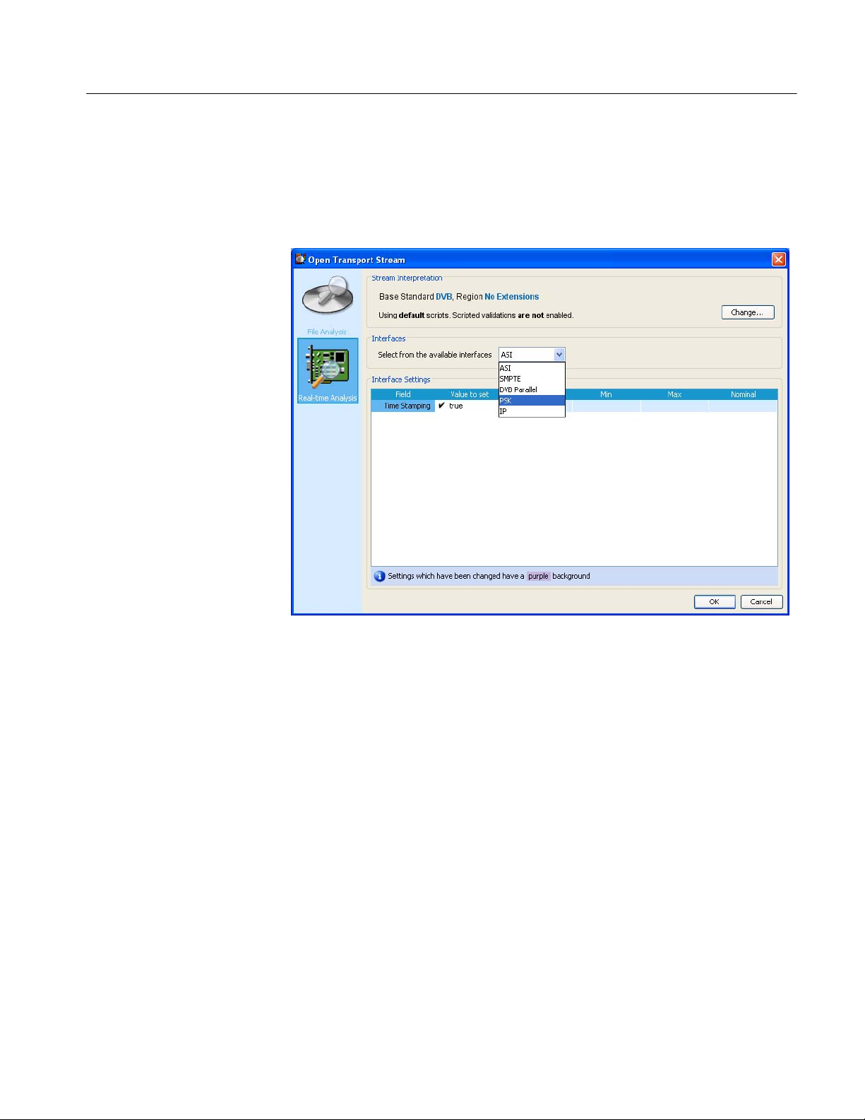
17. In the Open Transport Stream window, click Real-time Analysis.
18. Make the following setting changes in the Real-time Analysis display (see
Figure 2−6).
a. In the Interfaces drop-down box, select ASI and check that all of the
interface options for the unit are listed in the drop-down list.
b. In the Interfaces Settings section, click on the Time Stamping box until a
check mark appears.
2−8
Figure 2−6: Real Time Analysis display in the Open Transport Stream window
19. Click OK to close the Open Transport Stream window.
After a few seconds, the TS Compliance Analyzer window opens with the
analysis results of the ASI transport stream (see Figure 2−7).
MTS400 Series MPEG Test Systems Technical Reference

Performance Verification
20. Verify the following in the analyzer window:
H The TS Availability and Sync indicators at the bottom left of the
analyzer window are green.
H The bit rate readout at the bottom of the window reads 41.471 Mbps.
NOTE. It is normal if indicators other than the TS Availability and Sync turn red.
This merely indicates that the software is operating and has detected errors in
the transport stream.
Figure 2−7: ASI interface analysis results
MTS400 Series MPEG Test Systems Technical Reference
2−9

Performance Verification
Verifying the MPEG
Record Function
21. In the Record menu of the TS Compliance Analyzer, click Record Settings to
open the dialog box shown in Figure 2−8. Make the following setting
changes in the dialog box:
a. Enable Transport source (a green dot appears next to the selected
recording source).
b. Click on the ellipse box at the far right of the Path entry box to open the
Set Recording Name window.
c. In the Set Recording Name window (not shown), navigate to the
F:\ drive on the MTS400 Series system.
d. In the File Name box, enter the following file name:
record test.mpeg
e. Click Save to close the Set Recording Name window.
f. In the Record Settings window, enter 300 in the File Size entry box.
g. Select Manual as the Trigger type (a green dot appears next to the
selected trigger type).
h. Click on the “Activate this dialog when recording starts” box until a
check mark appears.
2−10
Figure 2−8: Record Settings dialog box
MTS400 Series MPEG Test Systems Technical Reference

Performance Verification
22. Click the Arm button. A red message appears in the Record Settings window
stating that the recording function is armed (see Figure 2−9).
Figure 2−9: Record Settings window with the recording function armed
23. Click the Start button. A red message appears in the Record Settings window
stating that the recording is currently in progress.
Observe the green bar showing the recording progress across the top of the
window. The recording should take about 30 seconds to complete. When the
recording is done, the progress bar says “Complete” as shown in Figure 2−8.
24. After the recording is finished, click Close to close the Record Settings
window.
MTS400 Series MPEG Test Systems Technical Reference
2−11

Performance Verification
25. Perform the following steps to verify that the transport stream file was
recorded to the F:\ drive of the instrument:
a. In the Record menu of the TS Compliance Analyzer, click Record
Settings to open the dialog box shown in Figure 2−8 on page 2−10.
b. Click on the ellipse box at the far right of the Path entry box to open the
Set Recording Name window.
c. In the Set Recording Name window, use the up arrow to navigate to the
F:\ drive on the MTS400 Series system.
d. Verify that the following file name appears:
record test.mpeg
e. Click Cancel to close the Set Recording Name window.
f. Click Close to close the Record Settings window.
26. Close the TS Compliance Analyzer by clicking Exit in the File menu.
2−12
MTS400 Series MPEG Test Systems Technical Reference

Performance Verification
Verifying the SMPTE310M
Interface
27. In the MPEG Player window, stop the player by clicking on the black Stop
button on the tool bar.
28. In the SPI/ASI/310M menu, click BNC Port, and then click 310M 8VSB.
29. Start the TS Compliance Analyzer by double clicking the
the desktop.
30. In the MPEG Player tool bar, click the green Play arrow to start playing the
transport stream file.
31. Verify that the TS rate displayed at the bottom of the MPEG Player window
displays the SMPTE310M rate of 19.392658 Mbps (see Figure 2−10).
icon on
Figure 2−10: MPEG Player playing a SMPTE310M transport stream
MTS400 Series MPEG Test Systems Technical Reference
2−13

Performance Verification
32. In the Open Transport Stream window, click Real Time Analysis.
33. In the Interfaces drop-down box, select SMPTE.
34. Click OK to close the Open Transport Stream window.
After a few seconds, the TS Compliance Analyzer window opens with the
analysis results of the SMPTE310M transport stream (see Figure 2−11 ).
35. Verify the following in the analyzer window:
H The TS Availability and Sync indicators at the bottom left of the
analyzer window are green.
H The bit rate readout at the bottom of the window reads 19.393 Mbps.
NOTE. It is normal if indicators other than the TS Availability and Sync turn red.
This merely indicates that the software is operating and has detected errors in
the transport stream.
36. Close the TS Compliance Analyzer by clicking Exit in the File menu.
2−14
Figure 2−11: SMPTE310M interface analysis results
MTS400 Series MPEG Test Systems Technical Reference

Performance Verification
Verifying the SPI Interface
37. In the MPEG Player window, stop the player by clicking on the black Stop
button on the tool bar.
38. Start the TS Compliance Analyzer by double clicking the
the desktop.
39. In the MPEG Player tool bar, click the green Play arrow to start playing the
transport stream file.
40. In the Open Transport Stream window, click Real Time Analysis.
41. In the Interfaces drop-down box, select DVB Parallel.
42. Click OK to close the Open Transport Stream window.
After a few seconds, the TS Compliance Analyzer window opens with the
analysis results of the SPI transport stream (see Figure 2−12).
43. Verify the following in the analyzer window:
H The TS Availability and Sync indicators at the bottom left of the
analyzer window are green.
H The bit rate readout at the bottom of the window reads 19.393 Mbps.
icon on
NOTE. It is normal if indicators other than the TS Availability and Sync turn red.
This merely indicates that the software is operating and has detected errors in
the transport stream.
44. Close the TS Compliance Analyzer by clicking Exit in the File menu.
MTS400 Series MPEG Test Systems Technical Reference
2−15

Performance Verification
RF Interfaces
Figure 2−12: SPI interface analysis results
The following steps ensure that any RF interfaces installed in the instrument is
available; only one interface can be installed at a time.
45. Start the TS Compliance Analyzer (TSCA) by double clicking the
icon on the desktop.
46. In the TSCA Open Transport Stream window, click Change... in the Stream
Interpretation section.
47. Make the following setting changes in the Stream Interpretation display
(see Figure 2−5).
a. Select DVB as the Base Standard.
b. Select No Extensions as the Region.
2−16
MTS400 Series MPEG Test Systems Technical Reference
Performance Verification
48. In the Open Transport Stream window, click Real-time Analysis.
49. In the Interfaces drop-down box, select the RF interface, for example, as
shown in Figure 2−13, PSK.
Figure 2−13: RF interface selection
50. Note that the Firmware version is current.
If the firmware version is not current, a message is displayed and the Update
Firmware button is activated. Click Update Firmware and allow the update
to complete.
51. Note that the Interface Settings are displayed. See Figure 2−14. If you want
to proceed with analysis, you may need to change the settings to suit your
local setup.
MTS400 Series MPEG Test Systems Technical Reference
2−17

Performance Verification
Shutting Down the
Instrument
Figure 2−14: RF interface settings
52. Click OK to close the Open Transport Stream window and proceed with
analysis.
After a few seconds, the TS Compliance Analyzer window opens with the
analysis results of the ASI transport stream (see Figure 2−7).
53. After you have checked the SPI interface, you have completed the Performance Verification procedures. Perform the following steps to power down
the instrument:
a. Select Shutdown from the Start menu. After the instrument shuts down,
you will see a message saying its safe to turn off the instrument.
b. Use the front-panel power switch to turn the instrument off.
c. Remove the two signal cables from the rear panel of the instrument.
d. Remove the power cord from the instrument.
2−18
MTS400 Series MPEG Test Systems Technical Reference
 Loading...