


xx
MTS4UP Upgrades
ZZZ
MTS400 Series and MTS400P MPEG Test Systems
Instructions
*P075097902*
075-0979-02


xx
MTS4UP Upgrades
ZZZ
MTS400 Series and MTS400P MPEG Test Systems
Instructions
Warning
The servicing instructions ar
only. To avoid personal injury, do not perform any servicing
unless you are qualified to do s
prior to performing service.
e for use by qualified personnel
o. Refer to all safety summaries
www.tektronix.com
075-0979-02

Copyright © Tektronix. All rights reserved. Licensed software products are owned by Tektronix or its subsidiaries
or suppliers, and are protected by national copyright laws and international treaty provisions.
Tektronix products are covered by U.S. and foreign patents, issued and pending. Information in this publication
supersedes that in all previously published material. Specifications and price change privileges reserved.
TEKTRONIX and TEK are registered trademarks of Tektronix, Inc.
Contacting Tektronix
Tektronix, Inc.
14150 SW Karl Braun Drive
P.O . Bo x 5 0 0
Beaverto
USA
For product information, sales, service, and technical support:
n, OR 97077
In North America, call 1-800-833-9200.
World wide, v isit www.tektronix.com to find contacts in your area.

Table of Contents
General Safety Summary .......................................................................................... ii
Service Safety Summary................ ................................ .................................. ........ iv
Kit Description................... ................................ ................................ ................... 1
Upgrade Kit
Minimum Tool and Equipment List .... ................................ ................................ ..... 3
Kit Parts Lists ............. ................................ ................................ ..................... 4
Upgrade Instructions Overview........................ ................................ ........................... 8
Option UPG Software Upgrade.............. .................................. ................................ ... 9
Software Option Upgrade......................................................................................... 14
Hardwar
Hardware Upgrade (MTS400P).......................................... .................................. ...... 38
SFP Module Upgrade (Option LX, Option SX, or Option ZX) .................... .......................... 53
e Upgrade (MTS400, MTS415, and MTS430)....................................................... 16
Access the Module Bay .................................. ................................ .................... 16
MTS4UP IPTVD Upgrade....................... ................................ ............................ 18
MTS4UP GBE Upgrade ..................... .................................. .............................. 21
MTS4UP CF, EP, QB2, or VS Upgrade .................................................................... 22
Replace the Cabinet .......................................................................................... 24
ore the Operating System. .................................. ................................ ............ 24
Rest
Software Upgrade..................... .................................. ................................ ...... 31
Software Key Upgrade ....................................................................................... 37
Software Upgrade..................... .................................. ................................ ...... 38
Access the Module Bay .................................. ................................ .................... 43
S4UP IPTVP Upgrade ................................................................................... 47
MT
s Covered by These Instructions.................................. ............................. 1
MTS4UP Upgrades Instruc tions i

General Safety Summary
General Safet
To Avoid Fi
re or Personal
Injury
ySummary
Review the fo
this product or any products connected to it.
To avoid pot
Only qualified personnel should perform service procedures.
Use proper
certified for the country of use.
Ground th
of the power cord. To avoid electric shock, the grounding conductor must be
connected to earth ground. Before making connections to the input or output
terminals of the product, ensure that the product is properly grounded.
Observe all terminal ratings. To av o i d fire or shock hazard, observe all ratings
and markings on the product. Consult the product manual for further ratings
information before making connections to the product.
Power disconnect. The power cord disconnects the product from the power source.
Donotblockthepowercord;itmustremain accessible to the user at all times.
llowing safety precautions to avoid injury and prevent damage to
ential hazards, use this product only as specified.
power cord. Use only the power cord specified for this product and
eproduct. This product is grounded through the grounding conductor
Do not operate without covers. Do not operate this product with covers or panels
removed.
Do not operate with suspected failures. If you suspect that there is damage to this
product, have it inspected by qualified service personnel.
Avoid exposed circuitry. Do not touch exposed connections and components when
power is present.
Use proper fuse. Use only the fuse type and rating specified for this product.
Do not operate in wet/damp conditions.
o not operate in an explosive atmosphere.
D
Keep product surfaces clean and dry.
Provide proper ventilation. Refer to the manual's installation instructions for details
on installing the product so it has proper ventilation.
ii MTS4UP Upgrades Instructions
General Safety Summary
TermsinThisManual
Symbols and Terms on the
Product
These terms may
WAR N ING. Warning statements identify conditions or practices that could result
in injury or loss of life.
CAUTION. Caution statements identify conditions or practices that could result in
damage to this product or other property.
These terms may appear on the product:
DANGER in
the marking.
WAR NI N G
read the marking.
CAUTIO
The following symbol(s) may appear on the product:
appear in this manual:
dicates an injury hazard immediately accessible as you read
indicates an injury hazard not immediately accessible as you
N indicates a hazard to property including the product.
MTS4UP Upgrades Instruc tions iii

Service Safety Summary
Service Safet
y Summary
Only qualifie
Safety Summary and the General Safety Summary before performing any service
procedures.
Do Not Service Alone. Do not perform internal service or adjustments of this
product unless another person capable of rendering first aid and resuscitation is
present.
Disconnect Power. To avoid electric shock, switch off the instrument power, then
disconnect the power cord from the mains power.
Use Care When Servicing With Power On. Dangerous voltages or currents may
exist in
disconnect test leads before removing protective panels, soldering, or replacing
components.
To avoid electric shock, do not touch e xposed connections.
d personnel should perform service procedures. Read this Service
this product. Disconnect power, remove battery (if applicable), and
iv MTS4UP Upgrades Instructions

Kit Description
This document provides instructions for performing hardware and/or software and
option key upgrades on the following Tektronix products:
MTS400 Series MPEG Test Systems (MTS400, MTS415, and MTS430)
MTS4SA MPEG Test System
MTS400P MPE
GTestSystem
Upgrade Kits Covered by These Instructions
MTS4UP UPG
systems. This upgrade is included with all of the hardware updates, or may
be ordered separately.
As the user of an MTS400 Series MPEG Test System, you will be familiar with
the software key (or dongle) that must be attached to your unit before you can
open any of the MTS400 Series applications. Two styles of software key are
available, each performs the same function: parallel port or USB (MTS4SA only).
The option key string supplied with this upgrade kit is generated using the serial
r of the software key and the list of options to be licensed.
numbe
NOTE. Only the software applications already installed on your MPEG test
system will be available after the upgrade. If additional applications are required,
contact your Tektronix representative.
MTS4UP IPTVD - This kit adds an IPTV Gigabit Ethernet interface with a
10/100/1000Base-T electrical port to your MTS400, MTS415, or MTS430
instrument. When you install the IPTV interface card you must remove any
other installed optional interface cards (options GBE, CF, EP, QB2, or VS).
- This kit provides a software upgrade for your MTS4xx
There are three o ptical length input options available for option IPTVD:
MTS4UP LX - Adds a 1000Base-LX wavelength optical port with LC
connector (single mode 1310 nm).
MTS4UP SX - Adds a 1000Base-SX short wavelength optical port with
LC connector (multimode 850 nm).
MTS4UP ZX - Adds a 1000Base-ZX wavelength optical port with LC
connector (multimode 1550 nm).
MTS4UP Upgrades Instruc tions 1

Kit Description
MTS4UP GBE - Thi
software to your MTS400, MTS415, or MTS430 instrument (SFP required).
This kit may be combined with any of the following hardware upgrade kits.
There are also four optical length input options available with option GbE:
MTS4UP LX - A
connector (single mode 1310 nm).
MTS4UP SX - A
LC connector (multimode 850 nm).
MTS4UP ZX -
connector (multimode 1550 nm).
MTS4UP CU
MTS4UP CF - This kit adds a COFDM DVB-T interface to your MTS400,
MTS415,
MTS4UP GBE kit.
MTS4UP
instrument. This kit may only be combined with the MTS4UP GBE kit.
MTS4U
instrument. This kit may only be combined with the MTS4UP GBE kit.
or MTS430 instrument. This kit may only be combined with the
EP - This kit adds a QPSK/8PSK interface to your MTS400 Series
PQB2-This kit adds a QAM B interface to your MTS400 Series
s kit adds a Gigabit Ethernet interface and IP Analysis
dds a 1000Base-LX wavelength optical port with LC
dds a 1000Base-SX short wavelength optical port with
Adds a 1000Base-ZX wavelength optical port with LC
- adds a 1000Base-T electrical port with RJ45 connector.
UP VS - This kit adds an 8VSB interface to your MTS400 Series
MTS4
instrument. This kit may only be combined with the MTS4UP GBE kit.
4UP IPTVP - This kit adds an IPTV Gigabit Ethernet interface with a
MTS
10/100/1000Base-T electrical port to your MTS400P.
ere are three optical length input options available for option IPTVP:
Th
MTS4UP LX - Adds a 1000Base-LX wavelength optical port with LC
nnector (single mode 1310 nm).
co
MTS4UP SX - Adds a 1000Base-SX short wavelength optical port with
C connector (multimode 850 nm).
L
MTS4UP ZX - Adds a 1000Base-ZX wavelength optical port with LC
connector (multimode 1550 nm).
2 MTS4UP Upgrades Instructions

Kit Description
MTS4UP <softwa
re option> – The following table lists the software options
that can be enabled in MTS400 Series systems.
MTS4UP options Description
MTS4UP BA Upgrade to add Buffer Analyzer
MTS4UP CG Upgrade to add Carousel G enerator
MTS4UP DB Upgrade to add Carousel Analyzer
MTS4UP DBCG Upgrade to add Carousel Generator and
Carousel Analyzer
MTS4UP ES Upgrade to add Elementary Stream Analyzer
MTS4UP MX Upgrade to add deferred time Multiplexer
MTS4UP PA Upgrade to add PES Analyzer
MTS4UP PB Upgrade to add PES and Buffer Analyzers
MTS4UP PL Upgrade to add Player to MTS400P
MTS4UP TSCA Upgrade to add deferred time Transport
Stream Compliance Analyzer
MTS4UP TSCL Upgrade to add Transport Stream
Compliance Analyzer Lite (limited file size)
MTS4UP TSCR Upgrade to add real time Transport Stream
Compliance Analyzer (MTS4SA only)
Minimum Tool and Equipment List
No tools are required to perform the software upgrade. The hardware upgrades
will require:
quired tools and equipment
Re
Anti-static wrist strap
crewdriver handle with T15 and T10 TORX
S
tip
rt number
Pa
tandard equipment
S
tandard equipment
S
MTS4UP Upgrades Instruc tions 3

Kit Description
Kit Parts Lists
MTS4UP UPG
This kit updates the software in an MTS400, MTS415, MTS430, MTS4SA, or
MTS400P MPEG Test System. The MTS4UP UPG software upgrade kit contains
these parts:
Quantity Part number Description
1 Each 063-4197-x
1 Each 020-2994-
1 Each 063-4220-00
1 Each 063-4220-01
1Each
1 Each 075-0979-02
1
NS - Not Saleable
NS
x
xx
1
SOFTWARE; DOCUMENTATION CD; MTS400 SERIES
SOFTWARE KIT; APPLICATION SOFTWARE MEDIA KIT;
MTS400 SERIES
MTS400 Series Version 1.7:
SOFTWARE
PROFESSIONAL, W/SP2B RECOV ERY MEDIA AND
NERO BURNING SOFTWARE, VER 1.7; MTS400 SERIES
MTS400 Series Version 1.9:
SOFTWAR
PROFESSIONAL, W/SP2B RECOV ERY MEDIA AND
NERO BURNING SOFTWARE, VER 1.9; MTS400 SERIES
IMPORTANT DOCUMENTS ENVELOPE, WITH
PRODUC
MANUA
PKG; MICROSOFT WINDOWS XP
E PKG; MICROSOFT WINDOWS XP
T OPTION KEY
L; UPGRADE INSTRUCTIONS; MTS4UP
MTS4UP IPTVD
This kit updates an MTS400, MTS415, or MTS430 MPEG Test System. The
MTS4UP IPTVD upgrade kit contains all the parts listed for the MTS4UP UPG
software upgrade kit, and these additional parts:
Quantity Part number Description
1 Each 671-6439-xx
1 Each 174-5336-xx
1 Each 174-5135-xx
2 Each 211-0722-xx
CIRCUIT BD ASSEMBLY, TESTED;MTS415/430;
389-3832-01 WIRED; SAFETY CONTROLLED
CABLE ASSEMBLY;5-PIN;RS232 INTERFACE BETWEEN
SBC AND RF CARD; 12.5 INCH L +/- .500; SAFETY
CONTROLLED
CABLE ASSY; RF, BNC TO BNC;75 OHM
SCREW, MACHINE ; 6-32 X 0.250, PNH, STL, ZINC
FINISH,T-15TORXDR
4 MTS4UP Upgrades Instructions

Kit Description
MTS4UP GBE
MTS4UP CF
This kit update
s an MTS400, MTS415, or MTS430 MPEG Test System. The
MTS4UP GBE upgrade kit contains all the parts listed for the MTS4UP UPG
software upgrade kit, and these additional parts:
Quantity Part number Description
1 Each 672-6300-xx
2 Each 211-0722-xx
This kit u
pdates an MTS400, MTS415, or MTS430 MPEG Test System. The
ASSEMBLY, C
OPTICAL EAGLE BOARD; PMC-0005-03-001, SAFETY
CONTROLLED
SCREW, MACHINE; 6-32 X 0.250, PNH, STL, ZINC
FINISH, T-
HEETAH II SPE-0028-03-002 AND
15 TORX DR
MTS4UP CF upgrade kit contains all the parts listed for the MTS4UP UPG
software upgrade kit, and these additional parts:
y
Quantit
1 Each 672-1780-xx
1 Each 174-53
1 Each 174-5135-xx
1 Each 015-0688-xx
2 Each 211-0722-xx
Part num
ber
36-xx
Descrip
TESTED
CONTROLLED
CABLE A SSEMBLY;5-PIN;RS232 INTERFACE BETWEEN
SBC AND RF CARD; 12.5 INCH L +/- .500; SAFETY
CONTR
CABLE
ADAP
SCRE
FINISH,T-15TORXDR
tion
SET, BASE BAND AND COFDM; SAFETY
OLLED
ASSY;RF , BNC TO BNC;75 OHM
TER, RF; BNC JACK TO F PLUG
W, MACHINE; 6-32 X 0.250, PNH, STL, ZINC
MTS4UP EP
This kit updates an MTS400, MTS415, or MTS430 MPEG Test System. The
MTS4UP EP upgrade kit contains all the parts listed for the MTS4UP UPG
software upgrade kit and these additional parts:
Quantity Part number Description
Each
1
1 Each 174-5336-xx
1 Each 174-5135-xx
2 Each 211-0722-xx
72-1781-xx
6
TESTED SET, BASE BAND AND 8PSK; SAFETY
CONTROLLED
CABLE A SSEMBLY;5-PIN;RS232 INTERFACE BETWEEN
SBC AND RF CARD; 12.5 INCH L +/- .500; SAFETY
CONTROLLED
CABLE ASSY;RF , BNC TO BNC;75 OHM
SCREW, MACHINE; 6-32 X 0.250, PNH, STL, ZINC
FINISH,T-15TORXDR
MTS4UP Upgrades Instruc tions 5

Kit Description
MTS4UP QB2
MTS4UP VS
This kit update
s an MTS400, MTS415, or MTS430 MPEG Test System. The
MTS4UP QB2 upgrade kit contains all the parts listed for the MTS4UP UPG
software upgrade kit and these additional parts:
Quantity Part number Description
1 Each 672-1782-xx
1 Each 174-5336-x
1 Each 174-5135-xx
2 Each 211-0722-00
This kit
updates an MTS400, MTS415, or MTS430 MPEG Test System. The
TESTED SET,
CONTROLLED
x
CABLE ASSEMBLY;5-PIN;RS232 INTERFACE BETWEEN
SBC AND RF CARD; 12.5 INCH L +/- .500; SAFETY
CONTROLLE
CABLE ASSY
SCREW,CA
BASE BAND AND QB2; SAFETY
D
;RF , BNC TO BNC;75 OHM
P; 6-32 X 0.75,HEX SKT,SST
MTS4UP VS upgrade kit contains all the parts listed for the MTS4UP UPG
software upgrade kit, and these additional parts:
ty
Quanti
1 Each 672-1783-xx
1Each 174-5
1 Each 174-5135-xx
1 Each 015-0688-xx
2 Each 211-0722-xx
Part nu
mber
336-xx
ption
Descri
D SET, BASE BAND AND 8VSB; SAFETY
TESTE
CONTROLLED
CABLE ASSEMBLY;5-PIN;RS232 INTERFACE BETWEEN
SBC AND RF CARD; 12.5 INCH L +/- .500; SAFETY
ROLLED
CONT
E ASSY;RF , BNC TO BNC;75 OHM
CABL
PTER, RF; BNC JACK TO F PLUG
ADA
REW,CAP; 6-32 X 0.75,HEX SKT,SST
SC
is kit updates an MTS400P MPEG Test System. The MTS4UP IPTVP upgrade
MTS4UP IPTVP
Th
kit contains all the parts listed for the MTS4UP UPG software upgrade kit, and
these additional parts:
uantity
Q
1 Each 671-6438-xx
1 Each 335-2072-xx
2 Each 343-1729-xx
1 Each 174-5626-xx
1 Each 174-5627-xx
art number
P
escription
D
CKT BD ASSY; VIDEO-GBE BD
MARKER, IDENT; MKD CONNECTORS FOR VIDEO-GBE
BD
RETAINER; VIDEO-GBE BD
CABLE ASSY; RF, BNC TO BNC; 75 OHM, 6.0 L
CABLE ASSY; RS 232 CIP
6 MTS4UP Upgrades Instructions

Kit Description
MTS4UP SX
MTS4UP LX
MTS4UP ZX
This kit adds an
850 nm optical port to an IPTVx module. The MTS4UP SX
upgrade kit contains all the parts listed for the MTS4UP UPG software upgrade
kit, and these additional parts:
Quantity Part number Description
1 Each 131-7834-xx
OPTICAL GIG
SFP, 1.25/1.0625GBAUD, 3.3V, SAFETY CONTROLLED
ABIT ETHERNET/FIBRE CHANNEL 850NM
This kit adds an 1310 nm optical port to an IPTVx module. The MTS4UP LX
upgrade kit contains all the parts listed for the MTS4UP UPG software upgrade
kit, and these additional parts:
Quantity Part number Description
1 Each 131-7957
This ki
t adds aN 1550 nm optical port to an IPTVx module. The MTS4UP ZX
-xx
OPTICAL GIGABIT ETHERNET/FIBRE CHANNEL
1310NM SFP SFF, 1.25/1.0625GBAUD, 3.3V, SAFETY
CONTROL
LED
upgrade kit contains all the parts listed for the MTS4UP UPG software upgrade
kit, and these additional parts:
ity
Quant
1 Each 131-7957-xx
Part n
umber
iption
Descr
CAL GIGABIT ETHERNET/FIBRE CHANNEL
OPTI
1550NM SFP, 1.25/1.0625GBAUD, 3.3V, SAFETY
CONTROLLED
MTS4UP Upgrades Instruc tions 7

Upgrade Instructions Overview
Upgrade Instr
uctions Overview
These instru
If you need further details for disassembling or reassembling the product, refer
to the appropriate product manual. Contact your nearest Tektronix, Inc., Service
Center or Tektronix Factory Service for installation assistance.
CAUTION. To prevent static discharge damage, service the product only
in a static-free environment. Observe standard handling precautions for
static-se
strap, grounded foot strap, and static resistant apparel while installing this kit.
Choose t
If you are installing Use this procedure
MTS4UP UPG software upgrade only (See page 9, Option UPG Software
MTS4U
Any of
MTS400, MTS415, or MTS430
Option IPTVP interface card into an
MTS400P
SFP optical port module (Option LX,
ion SX, or Option ZX) into an MTS400,
Opt
MTS415, MTS430, or MTS400P system that
already has an IPTV or GbE option installed
ctions are for personnel who are familiar with servicing the product.
nsitive devices while installing this kit. Always wear a grounded wrist
he correct upgrade procedure:
e.)
Upgrad
P <option> software upgrade only
the interface card options into an
age 14, Software Option Upgrade.)
(See p
age 16, Hardware Upgrade (MTS400,
(See p
MTS415, and MTS430).)
(See page 38, Hardware Upgrade
(MTS400P).)
(See page 53, SFP Module Upgrade (Option
Option SX, or Option ZX).)
LX,
8 MTS4UP Upgrades Instructions
Option UPG Software Upgrade
Option UPG Sof
tware Upgrade
Perform the f
key:
1. Ensure that
completed the start-up process.
2. Ensure tha
3. Insert the upgrade media into the instrument. An MTS400, MTS415,
MTS430, or
CD-ROM supplied with this kit, while an MTS400P will use the USB flash
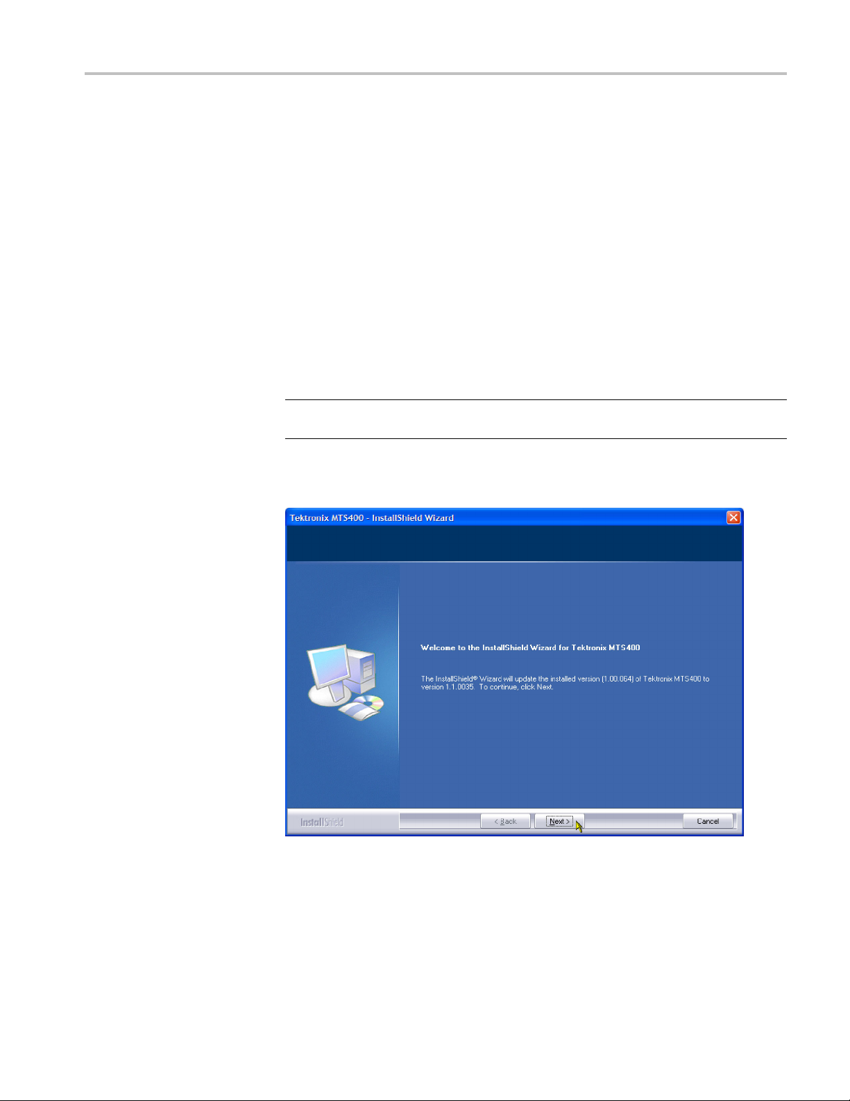
drive. The InstallShield Wizard will autostart and display the Welcome screen
showninFigure1.
NOTE. If the InstallShield Wizard fails to autostart, use Windows Explorer to
locate and run the following file on the media: start.exe.
4. Click Next to initiate the upgrade process. (See Figure 1.)
ollowing steps to upgrade the MTS400 Series software and software
theinstrumentorPCtobeupgradedisswitchedonandhas
t the software key (dongle) is attached to your instrument.
MTS4SA will use the MTS400 Series Application Install
Figure 1: InstallShield Wizard welcome screen
MTS4UP Upgrades Instruc tions 9
Option UPG Software Upgrade
5. Allow the insta
approximately five minutes.
NOTE. A number of dialog boxes are displayed during the installation process.
Normally, no user intervention is required.
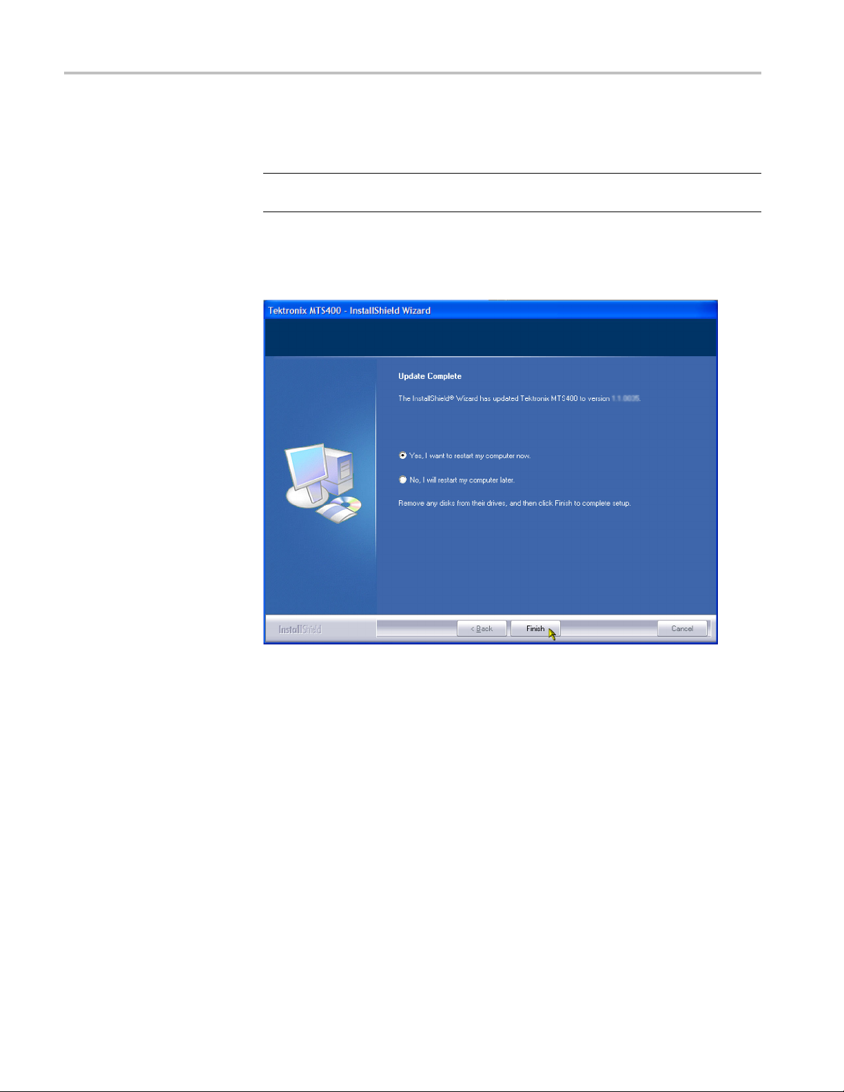
6. When the upgrade installation is complete, the Update Complete screen
is displayed. (See Figure 2.)
llation process to proceed. The average installation time is
Figure 2: InstallShield Wizard update complete screen
7. Select the Yes, I want to restart my computer now option, and then click
Finish. The instrument or PC will shut down and then restart.
8. When the unit has completed the start-up process, the Tektronix Option
Update wizard will start automatically. (See Figure 3.)
10 MTS4UP Upgrades Instructions
Option UPG Software Upgrade
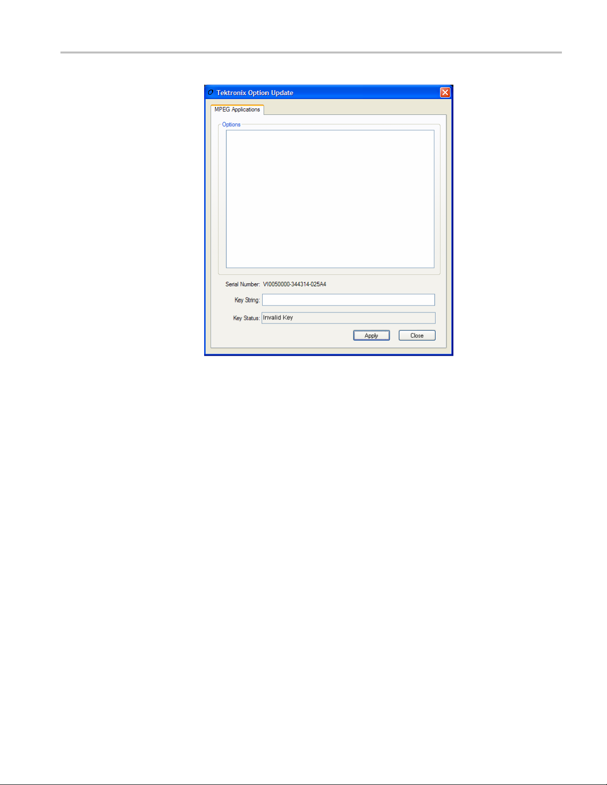
Figure 3
9. In the
: Tektronix Option Update Wizard - Initial view
Note th
Key Status is invalid because no Key String has been entered.
on the Product Option Key label supplied with these upgrade instructions, in
the Key String field. Click Apply.
at the Serial Number of the software key has been detected, b ut the
Tektronix Option Update dialog box, enter the Option Key String, found
MTS4UP Upgrades Instruc tions 11

Option UPG Software Upgrade
Figure 4: Tektronix Option Update Wizard - Complete
NOTE. T
Option Update dialog box may differ from the screenshots in these instructions.
10. Inspe
11. Close the Tektronix Option Update wizard.
12. Peel the backing off of the Product Option Key label and apply it to the
Theupgradeisnowcomplete.
he version numbers displayed in the Options pane of your Tektronix
ct and verify the list of licensed options.
instrument rear panel. (See Figure 5.) If there is already an option k ey label
he rear panel apply the new one over the old one.
on t
12 MTS4UP Upgrades Instructions

Figure 5: Product Option key label location
Option UPG Software Upgrade
Verify O
peration
To verify operation of the upgraded applications, open and close each installed
application in turn.
If any licensed application fails to open correctly, contact your Tektronix
representative.
MTS4UP Upgrades Instruc tions 13

Software Option Upgrade
Software Opti
on Upgrade
Perform the f
enable additional options:
1. Ensure that the instrument or PC to be upgraded is switched on and has
completed the start-up process.
2. Ensure that the software key (dongle) is attached to your instrument.
3. Select Start > Tektronix > MTS400 > OptionKey wizard to display the
Tektronix Option Update dialog box. (See Figure 6.)
ollowing steps to upgrade the MTS400 Series software key and
Figure 6: Tektronix Option Update Wizard
NOTE. The version numbers displayed in the Options pane of your Tektronix
Option Update dialog box may differ from the screenshots in these instructions.
Note that the Serial Number of the software key has been detected, and the
currently enabled options are displayed.
4. In the Tektronix Option Update dialog box, enter the Option Key String, found
on the Product Option Key label supplied with these u
the Key String field. Click Apply.
5. Inspect and verify the list of licensed options.
14 MTS4UP Upgrades Instructions
pgrade instructions, in

Software Option Upgrade
6. Close the Tektr
7. Peel the backing off of the Product Option Key label and apply it to the
instrument re
on the rear panel apply the new one over the old one.
onix Option Update wizard.
ar panel. (See Figure 7.) If there is already an option key label
y Operation
Verif
Figure 7: Product Option key label location
Theupgradeisnowcomplete.
To verify operation of the upgraded applications, open and close each installed
application in turn.
If any licensed application fails to open correctly, contact your Tektronix
representative.
MTS4UP Upgrades Instruc tions 15

Hardware Upgrade (MTS400, MTS415, and MTS430)
Hardware Upgr
ade (MTS400, MTS415, and MTS430)
Access the Module Bay
Use the follo
MTS400, MTS415, or MTS430 MPEG Test System.
WARNING. To avoid electric shock, switch off the instrument power, then
disconnect the power cord from the mains power. Failure to do so can cause
injury or d
In order to install any of the hardware upgrades you must first remove the cabinet
and the c
1. Power off the system and unplug the power cord.
2. Disconnect any cables from the rear panel. Note the location of any cables
for reinstallation.
3. Install the protective cover on the front of the instrument and place the cabinet
on the working surface with the rear panel facing up.
wing procedure to install any of the hardware upgrades into an
eath.
ircuit board retaining plate. Follow these steps to access the module bay:
4. Remove the handle from the side of the instrument and remove the four feet
from the rear of the instrument. Retain the screws for reinstallation.
ING. To prevent damage to the EMI shielding and injury to yourself, use
WARN
care when touching the EMI shielding strips around the front of the chassis. If
you accidentally bend the "fingers" of the strip, it could create sharp protruding
edges, which may cut you as you handle the chassis.
5. Use a wrench as a lever to pry the cabinet loose from the chassis. Loosen each
side alternately until the cabinet is released from the EMI gasket.
6. Slide the cabinet up and off the chassis.
7. Set the instrument onto the work surface so the bottom is down. (See
Figure 8.)
8. Remove the five T-15 screws securing the circuit board retaining plate to the
chassis and lift it away. (See Figure 8.)
16 MTS4UP Upgrades Instructions

Hardware Upgrade (MTS400, MTS415, and MTS430)
Figure 8: Removing the circuit board retaining plate
To continue, choose the correct upgrade procedure:
If you are installing Continue with this procedure
MTS4UP IPTVD IP Video Gigabit Ethernet
upgrade into an MTS400, MTS415, or
MTS430 Test System
MTS4UP GBE Gigabit Ethernet input
upgrade, with or without any of the other
hardware upgrades
MTS4UP CF, MTS4UP EP, MTS4UP QB2,
or MTS4UP VS upgrade without an MTS 4UP
GBE
(See page 18, MTS4UP IPTVD Upgrade.)
(See page 21, MTS4UP GBE Upgrade.)
(See page 22, MTS4UP CF, EP, QB2, or VS
Upgrade.)
MTS4UP Upgrades Instruc tions 17

Hardware Upgrade (MTS400, MTS415, and MTS430)
MTS4UP IPTVD U
pgrade
Perform the following steps to install the MTS4UP IPTVD, IP Video Gigabit
Ethernet interface. This module must be installed in slot 4.
1. Remove the two blank panels covering slots 4 and 5.
2. Align the hardware upgrade module over the slot 4 connector, with the edge
of the long card engaged in the slot 4 card guide, and slide the module down
into slot 4.
3. Press down firmly to engage the module into the slot 4 connector. (See
Figure 9.)
Figure 9: IPTVD IP Video Gigabit Ethernet Interface module in place
18 MTS4UP Upgrades Instructions

Hardware Upgrade (MTS400, MTS415, and MTS430)
4. Secure the hard
slot 4 blank panel in place.
5. Replace the sl
6. Attach the 2x5 connector end of the interface cable, provided in the kit, to the
COM2 connec
connector is keyed and can only be installed one way.
7. Connect the
module. (See Figure 11.)
ware upgrade module in place, using the screws that held the
ot 5 blank panel.
tor on the controller board in slot 11. (See Figure 10.) This
other end of the interface cable to J10 on the hardware upgrade
Figure 10: Interface cable connected to controller board
MTS4UP Upgrades Instruc tions 19

Hardware Upgrade (MTS400, MTS415, and MTS430)
Figure 11: Interface cable connected to the IPTVD module
This completes the MTS4UP IPTVD installation. Go to Replace the Cabinet.
page 24.)
(See
20 MTS4UP Upgrades Instructions

Hardware Upgrade (MTS400, MTS415, and MTS430)
MTS4UP GBE Upg
rade
Perform the following steps to install the MTS4UP GBE Gigabit Ethernet
interface:
1. Turn the instrument so the rear panel is facing you.
2. Remove the two blank panels covering slots 2 and 3.
3. Align the Gigabit Ethernet interface module over the slot 2 connector, with
the card edge engaged in the slot 2 card guide, and slide the module down
into slot 2. (See Figure 12.)
4. Press down firmly to engage the module into the connector. (See Figure 12.)
Figure 12: Gigabit Ethernet m odule in place
5. Secure the Gigabit Ethernet module in place, using the screws that held the
t 2 blank panel in place.
slo
6. Replace the slot 3 blank panel.
If you are installing any of the other hardware options at this time, continue with
the following MTS4UP CF, EP, QB2, or VS Upgrade Instructions.Otherwise,
otoRestore the Operating System. (Seepage24.)
g
MTS4UP Upgrades Instruc tions 21

Hardware Upgrade (MTS400, MTS415, and MTS430)
MTS4UP CF, EP,
QB2, or VS Upgrade
These hardware upgrades are all installed in a similar manner, and must be
installed in slot 4.
1. Remove the three blank panels covering slots 4, 5, and 6.
2. Align the hardware upgrade module over the slot 4 connector, with the edge
of the long card engaged in the slot 4 card guide, and slide the module down
into slot 4.
3. Press down firmly to engage the module into the slot 4 connector. (See
Figure 13.)
Figure 13: Hardware upgrade module installed in slot 4
4. Secure the hardware upgrade module in place, using the screws that held the
slot 4 and 5 blank panels in place.
5. Attach the 2x5 connector end of the interface cable provided in the kit to the
COM2 connector on the controller board in slot 11. (See Figure 14.) This
connector is keyed and can only be installed one way.
6. Connect the other end of the interface cable to J14 on the hardware upgrade
module. (See Figure 15.)
22 MTS4UP Upgrades Instructions

Hardware Upgrade (MTS400, MTS415, and MTS430)
Figure 14: Interface cable connected to controller board
Figure 15: Interface cable connected to the hardware upgrade module
MTS4UP Upgrades Instruc tions 23

Hardware Upgrade (MTS400, MTS415, and MTS430)
Replace the Ca
binet
Replace the circuit board retaining plate and the cabinet by reversing the Access
theModuleBayinstructions. (See page 16, Access the Module Bay.)
CAUTION. To
cables do not catch when you slide the cabinet back onto the chassis. Make sure
that the edges of the cabinet go under the retaining tabs around the front of the
chassis. You may have to push on the side of the cabinet to get all of the edges
under the tabs and over the EMI gasket.
At the rear of the chassis, you may have to push on the sides of the cabinet to get
the rear of the cabinet to fit over the edges of the chassis and EMI gasket.
Restore the Operating System
nstalling the hardware upgrade, you must restore the operating system to
After i
install the new application software and drivers required for the hardware.
CAUTION. Toavoidlosingaccesstoyourlicensed applications, you must use the
MTS400 Series System Recovery media supplied with this upgrade kit.
prevent damage to the instrument, make sure that the internal
If your MTS400 Series instrument has an 80 GB hard disk, you must use the
version 1.7 Operating System restore disk; Tektronix part number 063-4220-00.
If your MTS400 Series instrument has an 250 GB hard disk, you must use the
version 1.9 operating system restore disk; Tektronix part number 0 63-4220-01.
Failure to use the correct recovery disk may result in the hard disk being
incorrectly formatted.
24 MTS4UP Upgrades Instructions

Hardware Upgrade (MTS400, MTS415, and MTS430)
MTS400 Series Operating
System Restore
To restore the M
This restore process is effective only if the hard disk drive is still good. The
process will restore the operations system and the application software. (The
process should take less than one hour.)
CAUTION. To prevent data loss, back up your hard drive before you restore the
MTS400 Series system. All data on the hard drive will be destroyed during the
system rest
1. Start the MTS400 Series system.
2. Verify the size of the operating system disk (c:) and ensure that you are using
the correct restore disk. Refer to t he caution at the beginning of this section;
(See pag
3. During the boot process, insert the MTS400 Series System Operating System
Restore
application when the boot process finishes. (SeeFigure16.)
TS400 Series system operating system, use the following steps.
ore process.
e 24, Restore the Operating System.).
DVD in the CD-ROM d rive. The system will autostart the recovery
Figure 16: Operating system recovery application
MTS4UP Upgrades Instruc tions 25

Hardware Upgrade (MTS400, MTS415, and MTS430)
4. Press the "1" ke
dialog box will appear briefly and display a progress bar.
5. When the syste
key. (See Figure 17.)
y to begin the system restore process. The Acquiring Device...
m restore is complete, press any key and then press the "4"
e 17: Restore Complete
Figur
6. When p
DVD from the CD-ROM drive while the system is rebooting.
7. On st
onscreen procedure, accepting the license agreement and defaults where
necessary.
NOTE. The screen will go blank for a few minutes during this process. Do not
turn the instrument off.
8. The system will restart on its own.
rompted, press the "Y" key to reboot the instrument. Remove the
artup, the system will prompt you to set up Windows XP. Follow the
26 MTS4UP Upgrades Instructions

Hardware Upgrade (MTS400, MTS415, and MTS430)
Reinstate the SCSI Drives
After restorin
SCSI drives (drives E and F) have been recognized by the system. (See Figure 18.)
g the operating system, use Windows Explorer to confirm that the
Figure
If the S
Computer Management window, and then proceed with the Software Upgrade
Instructions. (Seepage31.)
If the SCSI drives E and F are not listed in Windows Explorer, continue with the
following procedure to allow them to be recognized by the system.
18: SCSI drives automatically recognized
CSI drives (drives E and F) have been recognized by the system, close the
MTS4UP Upgrades Instruc tions 27

Hardware Upgrade (MTS400, MTS415, and MTS430)
Import the SCSI
complete the following procedure.
1. Open the Windo
Performance and Maintenance > Administrative Tools > Computer
Management > Storage > Disk management).
Note that Disk 0 and Disk 1 are described as Foreign. (See Figure 19.)
drives. If drives E and F are not listed in Windows Explorer,
ws Disk Management window (Start > Control Panel >
Figure 19: Computer Management - SCSI drives, foreign
2. Right-click o n Disk 0 or Disk 1 and select Import Foreign Disks... from
shortcut menu. (See Figure 20.)
the
28 MTS4UP Upgrades Instructions

Hardware Upgrade (MTS400, MTS415, and MTS430)
Figure 20
3. In the Im
Figure 21: Import Foreign Disks dialog box
4. In the Foreign Disk Volumes dialog box, select OK. (See Figure 22.)
: Select Import Foreign Disks...
port Foreign Disks dialog box, ensure that the disk group is checked
and select OK. (See Figure 21.)
Figure 22: Foreign Disk Volumes dialog box
MTS4UP Upgrades Instruc tions 29

Hardware Upgrade (MTS400, MTS415, and MTS430)
5. This takes a lit
(See Figure 23.)
tle time. Wait until the drives appear in the upper window.
Figure 2
If the S
1. Copy the file "SCSIKeyDel.reg" from the restore DVD to your C: drive.
2. Double-click the file to execute it.
3. When prompted to add information to the registry, press "Yes."
4. When the information successfully entered message appears, press "OK."
5. Reboot the MTS400 platform.
6. Imp
This completes the MTS400 Operating System Restore Procedure. Close the
Co
described in the following procedure.
3: SCSI drives manually recognized
CSI drives fail to import, follow this procedure:
ort the SCSI drives again. (See page 28, Import the SCSI drives.)
mputer Management window. You must now upgrade the software, as
30 MTS4UP Upgrades Instructions

Hardware Upgrade (MTS400, MTS415, and MTS430)
Software Upgr
ade
Perform the following steps to upgrade the MTS400 Series software and software
key:
1. Ensure that the instrument or PC to be upgraded is switched on and has
completed the start-up process.
2. Ensure that the software key (dongle) is attached to your instrument.
3. Insert the MTS400 Series Application Install CD-ROM supplied with this
kit into the CD-ROM drive of the instrument or PC to be upgraded. The
CD-ROM will autostart and display the Welcome screen. (See Figure 24.)
NOTE. If t
the following file on the CD-ROM: start.exe.
he CD-ROM fails to autostart, use Windows Explorer to locate and run
gure 24: InstallShield Wizard welcome screen
Fi
MTS4UP Upgrades Instruc tions 31

Hardware Upgrade (MTS400, MTS415, and MTS430)
4. Click Next.
If you have not installed Option GBE, just accept the defaults during
the upgrade pr
procedure.
ocess and restart when complete. Go to step 13 of this
If you have i
displayed, which allows you to select the type of installation. (See
Figure 25.) Continue to step 5 of this procedure.
nstalled Option GBE the Setup Type dialog box will be
Figure 25: MTS400 Installation - Setup Type
5. Choose and select Next.
6. Allow the installation process to proceed. The average installation time is
approximately five minutes.
NOTE. A number of dialog boxes are displayed during the installation process.
rmally, no user intervention is required.
No
32 MTS4UP Upgrades Instructions

Hardware Upgrade (MTS400, MTS415, and MTS430)
7. Allow the insta
box is displayed. (See Figure 26.)
NOTE. If WinPcap has been previously installed, the following message will be
displayed:
WinPcap 3.1 is already installed on this machine. The installation will be aborted.
Select OK to abort the WinPcap installation and continue with the
MTS400 installation.
llation process to proceed until the WinPcap Setup dialog
Figure 26: WinPcap Setup dialog
8. In the WinPcap Setup dialog box, select Next.
9. The WinPcap License agreement is displayed. Read the agre ement and select
IAgreeif you agree.
10. When the WinPcap completed dialog appears, click FINISH.
MTS4UP Upgrades Instruc tions 33

Hardware Upgrade (MTS400, MTS415, and MTS430)
11. When the upgrad
displayed. (See Figure 27.)
e installation is complete, the Update Complete screen is
Figure
12. Select
27: InstallShield Wizard update complete screen
the Yes, I want to restart my computer now option, and then click
Finish. The instrument or PC will shut down and then restart.
34 MTS4UP Upgrades Instructions

Hardware Upgrade (MTS400, MTS415, and MTS430)
13. After the unit h
Update wizard by selecting Start > Programs > Tektronix MTS400
> OptionKey Wizard. The Option Update window should open. (See
Figure 28.)
as completed the start-up process, start the Tektronix Option
Figure 28: Tektronix Option Update Wizard - Initial view
Note that the Serial Number of the software key has been detected, but the
Key Status is invalid because no Key String has been entered.
14. In the Tektronix Option Update dialog box Key String field, enter the Option
Key String, found on the Product Option Key label supplied with these
upgrade instructions, and then click Apply.
MTS4UP Upgrades Instruc tions 35

Hardware Upgrade (MTS400, MTS415, and MTS430)
15. Inspect and ver
ify the list of licensed options. (See Figure 29.)
ify Op eration
Ver
Figure 29: Tektronix Option Update Wizard - Complete
16. Close the Option Key Wizard.
17. Peel the backing off of the Product Option Key label and apply it to the
instrument rear panel. (See Figure 7 on page 15.) If there is already an option
key label on the rear panel, paste the new one over the old one.
The upgrade is now complete. The licensed MTS400 applications will now be
available in the Windows Start menu.
For complete verification, perform the Performance Verification procedure found
in the Specifications and Performance Verification manual (071-1724-xx), on the
documentation CD included in this kit.
If any licensed application fails to open correctly, c ontact your Tektronix
representative.
36 MTS4UP Upgrades Instructions

Hardware Upgrade (MTS400, MTS415, and MTS430)
Software Key U
pgrade
Perform the following steps to upgrade the MTS400 software key. This process
can be used where a new application is to be licensed on an MTS400, software
version 1.4 o
1. Ensure that the software key (dongle) is attached to your instrument.
2. Switch the instrument on and allow the start-up process to complete.
3. Start the Tektronix Option Update Wizard (Start > Programs > Te kt r oni x
MTS400 > OptionKey Wizard).
4. In the Tektronix Option Update Wizard dialog box, enter the Option Key
String, found on the Product Option Key label supplied with these upgrade
instructions, in the Key String field. Click Apply.
5. Inspect and verify the list of licensed options.
6. Close the Option Key Wizard.
7. Peel the backing off of the Product Option Key label and apply it to the
instrument rear panel. (See Figure 7 on page 15.) If there is already an option
key label on the rear panel, paste the n ew one over the old one.
Thesoftwarekeyupgradeisnowcomplete.
r later, but the software does not require an upgrade.
Verify Operation
To verify operation of the upgraded applications, open and close each installed
application in turn.
If any licensed application fails to open correctly, contact your Tektronix
representative.
MTS4UP Upgrades Instruc tions 37

Hardware Upgrade (MTS400P)
Hardware Upgr
Software U
pgrade
ade (MTS400P)
Use these pro
CAUTION. To ensure that the instrument functions properly after the upgrade
procedures, perform the software upgrades before the hardware upgrades.
Perform the following steps to upgrade the software, using the USB flash drive
and the UPG option.
1. Connect the USB flash drive to the USB connector of the instrument. A
dialog box with various install options is displayed.
cedures to install an MTS4UP IPTVP into an MTS400P.
38 MTS4UP Upgrades Instructions

Hardware Upgrade (MTS400P)
2. Select Install
Immediately, an InstallShield Wizard that allows you to install the application
is displayed. Click Next to continue.
3. Select MTS400P as the Setup type and click Next to continue.
Tektronix MPEG Application Suite and click OK.
MTS4UP Upgrades Instruc tions 39

Hardware Upgrade (MTS400P)
4. Click Install t
During the progress, the following WinPcap 4.0.2 Setup message is displayed.
Click OK to continue.
o begin the installation process.
5. Choose the option to restart the PC, and then select Finish. The PC will shut
down and restart.
40 MTS4UP Upgrades Instructions

Hardware Upgrade (MTS400P)
6. After the resta
No, not this time option and click Next to proceed. Follow the on screen
instructions, and the wizard automatically installs the hardware driver.
rt, a Hardware Update Wizard dialog box is displayed. Choose
7. Continue with the following procedure to enter the UPG option key.
MTS4UP Upgrades Instruc tions 41

Hardware Upgrade (MTS400P)
Entering the Option Key
Perform the fol
upgrade kit.
1. Connect the do
2. From the Start menu, select Programs > Tektronix MTS400 > Optionkey
Wizard to op
lowing steps to enter the option key that is supplied with the
ngle that is supplied with the instrument.
en the Tektronix Option Update dialog box. (See Figure 30.)
Figure 30: Tektronix Option Update dialog box
3. Refer to the option key document that is supplied with the kit to identify the
option key numbers.
4. Enter the alphanumeric numbers in the Key String text box, and click the
Apply button.
The Tektronix Option Update dialog box is updated and the ordered option is
displayed along with the other options. If a wrong key string is entered, the
y Status box displays the entered string as invalid.
Ke
5. Apply the label of the ordered option to the right side of the cabinet.
6. Restart the instrument to display the application screen.
42 MTS4UP Upgrades Instructions
Access the Module Bay
Hardware Upgrade (MTS400P)
CAUTION. To prevent static discharge damage, service the product only
in a static-fr
static-sensitive devices while installing this kit. Always wear a grounded wrist
strap, grounded foot strap, and static resistant apparel while installing this kit.
WAR N ING. Dangerous voltages may be present inside the instrument. Before
performing the hardware procedures, disconnect the power cord from the line
voltage source. Failure to do so could cause serious injury.
Perform the following procedure to install an Option IPTVP interface module
into the MTS400P:
ee environment. Observe standard handling precautions for
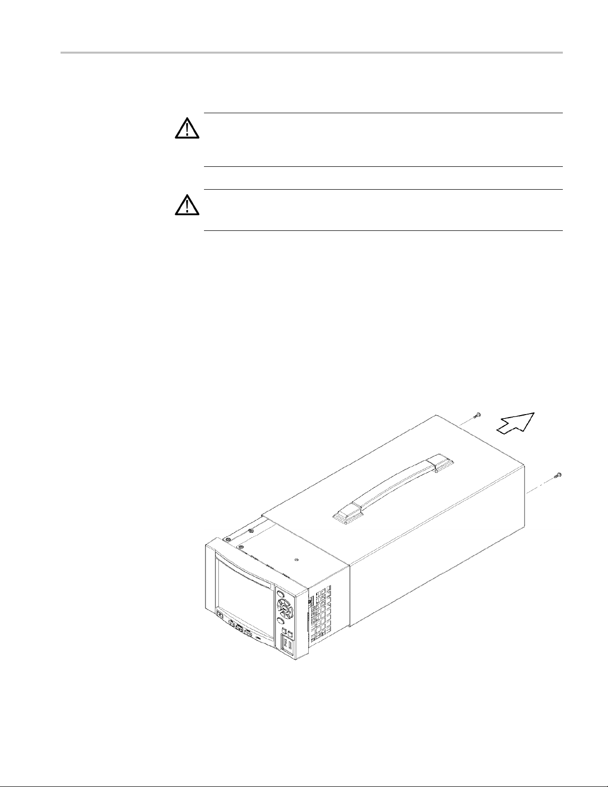
Remove the Cabinet
1. Disconnect all external cables and the power cord from the MTS400P rear
panel.
2. Use a screwdriver with a T15 TORX tip to remove the two screws securing
the cabinet to the instrument. (See Figure 31.)
3. Slide the instrument forward to remove the instrument from the cabinet.
(See Figure 31.)
Figure 31: Removing the MTS400P cabinet
MTS4UP Upgrades Instruc tions 43
Hardware Upgrade (MTS400P)
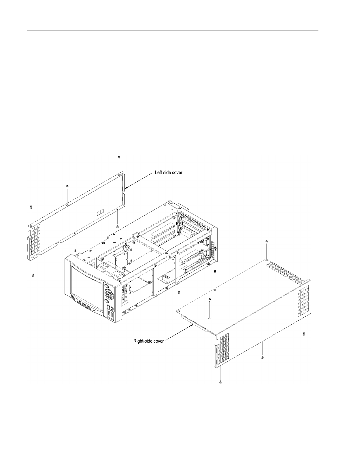
Remove the Right-side and
Left-side Covers
1. Set the instrum
front is facing you.
2. Useascrewdri
the right-side cover to the top and bottom of the chassis. (See Figure 32.)
3. Remove the r
4. Set the instrument so that the right side is down on the work surface and
the front is
5. Use a screwdriver with a T10 TORX tip to remove the six screws securing the
left-side
6. Remove the left-side cover from the chassis.
ent so that the left side is down on the work surface and the
ver with a T10 TORX tip to remove the seven screws securing
ight-side cover from the chassis.
facing you.
cover to the top and bottom of the chassis. (See Figure 32.)
Figure 32: Removing the right-side and left-side covers
44 MTS4UP Upgrades Instructions

Hardware Upgrade (MTS400P)
Remove the Board
Retainers
1. Set the instrum
rightsideisfacingyou.
2. Use a screwdri
the board retainers to the chassis. (See Figure 33.)
3. Lift the ret
ent so that the bottom is down on the work surface and the
ver with a T10 TORX tip to remove the two screws securing
ainers away from the chassis. (See Figure 33.)
Figure 33: Removing the board retainers
MTS4UP Upgrades Instruc tions 45

Hardware Upgrade (MTS400P)
Remove the Blank Panel
Use a screwdriv
of the chassis, that secure the top blank panel.
1. Lift the blank
er with a T10 TORX tip to remove the screws to the side and rear
panel away to remove it. (See Figure 34.) Save the screws.
Figure
34: Removing the top blank panel
46 MTS4UP Upgrades Instructions

Hardware Upgrade (MTS400P)
MTS4UP IPTVP U
Install the O
ption IPTVP
Cable
pgrade
Perform the following steps to install the MTS4UP IPTVD, IP Video G igabit
Ethernet interface.
1. Locate the A170 SMPTE310M/ASI/SPI Interface (slot 2) and the A12 Main
2. Remove the screws securing the A170 SMPTE310M/ASI/SPI Interface board
3. Gently remove the A170 SMPTE310M/ASI/SPI Interface board from the
4. Remove the screws securing the A12 Main board to the instrument and set
5. Gently remove the A12 Main board from the instrument and set it aside.
6. On the p
board (slot 3).
and set them aside.
instrument and set it aside.
them aside.
rocessor board at the bottom of the instrument:
a. Move the jumper on JP2 to pins 1 and 2. (See Figure 35.)
b. Connect one end of the RS232 CIP cable, provided in the kit, to CN13.
(See Figure 35.)
Figure 35: Jumper and RS232 CIP cable connection on Processor board
MTS4UP Upgrades Instruc tions 47

Hardware Upgrade (MTS400P)
7. Route the new ca
You will connect the other end of the cable later.
Figure 36: RS232 CIP cable routing
ble across the bottom of the instrument. (See Figure 36.)
Install the Option IPTVP
Gigabit Ethernet interface
8. Carefully reinstall the A12 Main and A 170 SMPTE310M/ASI/SPI Interface
boards into the instrument, using care to not pinch the new RS232 CIP cable.
Push each module in until the m odule edge-connector is firmly seated in the
A20 PCI backplane connector.
9. Reinstall the screws that secure the A170 and A12 boards to the instrument.
Perform the following steps to install the Option IPTVP interface module.
CAUTION. The cables and parts of the interface module can be damaged if you
improperly insert the module into the instrument. To avoid damaging any parts,
use care when you insert the module into the instrument.
1. Insert the interface module into the upper card slot (slot 1), paying attention to
the module orientation. (See Figure 37.)
2. Push the IPTVP m odule in until the board-edge connector is firmly seated in
the A20 PCI Backplane board connector.
3. Secure the interface module at the side and rear of the chassis, using the two
screws that were removed from the top blank panel.
48 MTS4UP Upgrades Instructions

Hardware Upgrade (MTS400P)
Figure 37
4. Connect
: Installing the Option IPTVP interface module
the free end of the new RS232 CIP cable t o J10 on the interface
module. (See Figure 38.)
gure 38: Connect the RS232 CIP cable to the IPTVP module
Fi
MTS4UP Upgrades Instruc tions 49

Hardware Upgrade (MTS400P)
Install the Board Retainers
Install the two
screwdriver with a T10 TORX tip to install the screws (removed with the original
board retainers) that secure the board retainers to the chassis.
Figure 39: Installing the Option IPTVP board retainers
new board retainers provided in the kit. (See Figure 39.) Use a
Install the Right-side and
Left-side Covers
Install the Cabinet
1. Use a sc
the right-side cover to the top and bottom of the chassis.
2. Use a s
left-side cover to the top and bottom of the chassis.
1. Slide the instrument into the cabinet.
2. Use a screwdriver with a T15 TORX tip to install the two screws securing
the cabinet to the instrument.
rewdriver with a T10 TORX tip to install the seven screws securing
crewdriver with a T10 TORX tip to install the six screws securing the
50 MTS4UP Upgrades Instructions

Hardware Upgrade (MTS400P)
Apply the Connector Label
Remove the prot
kit, and then apply it to the rear-panel frame, just below the installed module.
(See Figure 40.)
ective backing from the connector label that is provided in the
Connect the BNC Cable
Figure 40: Apply the connector label
Connect the BNC cable, provided in the kit. (See Figure 40.)
MTS4UP Upgrades Instruc tions 51

Hardware Upgrade (MTS400P)
Enable COM2
Perform the fol
1. Connect the keyboard and mouse to the instrument.
2. Power on the instrument and press the Delete key when the instrument
displays "Press DEL to enter SETUP" at the bottom of the screen. The BIOS
setup utili
3. Select Integrated Peripheral, and then set the Onboard Serial Port 2 setting
to 2F8 to ena
lowing steps to enable COM2:
ty window appears.
ble COM2. (See Figure 41.)
Figure 41: Enabling COM2
52 MTS4UP Upgrades Instructions

SFP Module Upgrade (Option LX, Option SX, or Option ZX)
SFP Module Upg
rade (Option LX, Option SX, or Option ZX)
The Option IP
remotely monitor and measure the quality of video-over-copper and optical IP
networks. The SFP (Small Format Pluggable) modules are available to facilitate
different optical wavelengths.
WAR N ING. To avoid exposure to hazardous laser radiation, use only Class 1
lasers as defined in the USA Federal Regulations CDRH 21 CFR 1040 and
IEC/EN 608
CAUTION. To prevent static discharge damage, service the product only
in a static-free environment. Observe standard handling precautions for
static-sensitive devices while installing this module. Always wear a grounded
wrist strap, grounded foot strap, and static resistant apparel while installing
this mo
The following figure shows an SFP module with the optical port plug removed.
Use the plug to protect the optical interface when no cable is connected or the
module is not in use.
dule.
TVP IP Video Gigabit Ethernet (GbE) interface card allows you to
25/A2:2001.
NOTE. The optical port plug must be in place when no cable is connected.
NOTE. The following illustrations show an MTS400P MPEG Te st System, but the
installation and removal steps are the same for any MTS400 Series instrument.
MTS4UP Upgrades Instruc tions 53

SFP Module Upgrade (Option LX, Option SX, or Option ZX)
SFP Installation
Perform the fol
interface module:
CAUTION. To avoid damage to the SFP module, remove power from the MS400P
instrument before removing or inserting an SFP module.
1. Disconnect the power cord from the instrument.
2. Insert the SFP module into the connector labeled SFP 1000 on the rear panel
of the module. When pushed in fully, the module latches into position.
3. Remove the optical port plug and insert the optical fiber cable into the SFP
module. (See Figure 42.) When pushed in fully, the cable connector latches
into position. Retain the optical port plug for later use when you need
to disconnect the optical fiber cable or remove the SFP module from the
instrument.
4. Reconnect the power cord to the instrument.
lowing steps to install an SFP module into the IPTV or GbE
Figure 42: Optical cable connected
54 MTS4UP Upgrades Instructions

SFP Module Upgrade (Option LX, Option SX, or Option ZX)
SFP Removal
Perform the fol
GbE interface module:
1. Disconnect th
2. Press the top of the SFP module connector to unlatch the optical fiber cable,
andthendis
3. Flip down the SFP module retaining latch, and then remove the module from
the instrum
Figure 43: SPF module removal
lowing steps to remove an SFP module from the Option IPTVP or
e power cord from the instrument.
connect and withdraw the cable from the SFP module.
ent. (See Figure 43.)
4. Install an optical port plug into the removed SFP module to protect the optical
port interface.
5. Reconnect the power cord to the instrument.
End of document
MTS4UP Upgrades Instruc tions 55
 Loading...