


x
MTS400P
MPEG Test System
ZZZ
Quick Start User Manual
*P071261002*
071-2610-02


xx
MTS400P
MPEG Test System
ZZZ
Quick Start User Manual
www.tektronix.com
071-2610-02

Copyright © Tektronix. All rights reserved. Licensed software products are owned by Tektronix or its subsidiaries or suppliers, and are
protected by na
tional copyright laws and international treaty provisions.
Tektronix pro
previously published material. S pecifications and price change privileges reserved.
TEKTRONIX and TEK are registered trademarks of Tektronix, Inc.
ducts are covered by U.S. and foreign patents, issued and pending. Information in this publication supersedes that in all
Contacting Tektronix
Tektronix, Inc.
14150 SW Karl Braun Drive
P.O. Box 500
Beaverton, OR 97077
USA
For product information, sales, service, and technical support:
In North America, call 1-800-833-9200.
Worldwide, visit www.tektronix.com to find contacts in your area.

Warranty
Tektronix warrants that this product will be free from defects in materials and workmanship for a period of one (1) year from the date of
shipment. If any such product proves defective during this warranty period, Tektronix, at its option, either will repair the defective
product without charge for parts and labor, or will provide a replacement in exchange for the defective product. Parts, modules and
replacement products used by Tektronix for warranty work may be new or reconditioned to like new performance. All replaced
parts, modules and products become the property of Tektronix.
In order to obtain service under this warranty, Customer must notify Tektronix of the defect before the expiration of the warranty period
and make suitable arrangements for the performance of service. Customer shall be r esponsible for packaging and shipping the
defective product to the service center designated by Tektronix, with shipping charges prepaid. Tektronix shall pay for the return of the
product to Customer if the shipment is to a location within the country in which the Tektronix service center is located. Customer shall
be responsible for paying all shipping charges, duties, taxes, and any other charges for products returned to any other locations.
This warranty shall not apply to any defect, failure or damage caused by improper use or improper or inadequate maintenance and
care. Tektronix shall not be obligated to furnish service under this warranty a) to repair damage resulting from a ttempts by personnel
other than Tektronix representatives to install, repair or service the product; b) to repair damage resulting from improper use or
connection to incompatible equipment; c) to repair any damage or malfunction caused by the use of non-Tektronix supplies; or
d) to service a product that has been modified or integrated with other products when the effect of such modification or integration
increases the time or difficulty of servicing the product.
THIS WARRANTY IS GIVEN BY TEKTRONIX WITH RESPECT TO THE PRODUCT IN LIEU OF ANY OTHER WARRANTIES,
EXPRESS OR IMPLIED. TEKTRONIX AND ITS VENDORS DISCLAIM ANY IMPLIED WARRANTIES OF MERCHANTABILITY OR
FITNESS FOR A PARTICULAR PURPOSE. TEKTRONIX’ RESPONSIBILITY TO REPAIR OR REPLACE DEFECTIVE PRODUCTS
IS THE SOLE AND E XCLU S IVE REMEDY PROVIDED TO THE CUSTOMER FOR BREACH OF THIS WARRANTY. TEKTRONIX
AND ITS VENDORS WILL NOT BE LIABLE FOR ANY INDIRECT, SPECIAL, INCIDENTAL, OR CONSEQUENTIAL DAMAGES
IRRESPECTIVE OF WHETHER TEKTRONIX OR THE VENDOR HAS ADVANCE NOTICE OF THE POSSIBILITY OF SUCH
DAMAGES.
[W2 – 15AUG04]

Warranty
Tektronix warrants that the media on which this software product is furnished and the encoding of the programs on the media will be
free from defects in materials and workmanship for a period of three (3) months from the date of shipment. If any such medium or
encoding proves defective during the warranty period, Tektronix will provide a replacement in exchange for the defective medium.
Except as to the media on which this software product is furnished, this software product is provided “as is” without warranty of any
kind, either express or implied. Tektronix does not warrant that the functions contained in this software product will meet Customer’s
requirements or that the operation of the programs will be uninterrupted or error-free.
In order to obtain service under this warranty, Customer must notify Tektronix of the defect before the expiration of the warranty
period. If Tektronix is unable to provide a replacement that is free from defects in materials and workmanship within a reasonable
time thereafter, Customer may terminate the license for this software product and return this software product and any associated
materials for credit or refund.
THIS WARRANTY IS GIVEN BY TEKTRONIX WITH RESPECT TO THE PRODUCT IN LIEU OF ANY O THER WARRANTIES,
EXPRESS OR IMPLIED. TEKTRONIX AND ITS VENDORS DISCLAIM ANY IMPLIED WARRANTIES OF MERCHANTABILITY OR
FITNESS FOR A PARTICULAR PURPOSE. TEKTRONIX’ RESPONSIBILITY TO REPLACE DEFECTIVE MEDIA OR REFUND
CUSTOMER’S PAYMENT IS THE SOLE AND EXCLUSIVE REMEDY PROVIDED TO THE CUSTOMER FOR BREACH OF
THIS WARRANTY. TEKTRONIX AND ITS VENDORS WILL NOT BE LIABLE FOR ANY INDIRECT, SPECIAL, INCIDENTAL, OR
CONSEQUENTIAL DAMAGES IRRESPECTIVE OF WHETHER TEKTRONIX OR THE VENDO R HAS ADVANCE NOTICE OF THE
POSSIBILITY OF SUCH DAMAGES.
[W9b – 15AUG04]

IMPORTANT
READ BEFORE OPERATING E QUIPMENT
This software
program in any manner constitutes acceptance of the license terms.
CAREFULLY READ THE ENCLOSED SOFTWARE LICENSE AGREEMENT. If you cannot agree to the license terms, promptly
contact the nearest Tektronix Field Office for return assistance.
is provided under license from Tektronix, Inc. Retention of this program for more than thirty (30) days or use of the
TEKTRONIX SOFTWARE LICENSE AGREEMENT
THE PROGRAM, OR PROGRAMS, ENCODED OR INCORPORATED WITHIN EQUIPMENT, IS FURNISHED SUBJECT TO
THE TERMS AND CONDITIONS OF THIS AGREEMENT. RETENTION OF THE PROGRAM FOR MORE THAN THIRTY DAYS
OR USE OF THE PROGRAM IN ANY MANNER WILL BE CONSIDERED ACCEPTANCE OF THE AGREEMENT TERMS. IF
THESE TERMS ARE NOT ACCEPTABLE, THE UNUSED PROGRAM AND ANY ACCOMPANYING DOCUMENTATION SHOULD
BE RETURNED PROMPTLY TO TEKTRONIX FOR A FULL REFUND OF THE LICENSE FEE PAID. (FOR INFORMATION
REGARDING THE RETURN OF PROGRAMS ENCODED OR INCORPORATED WITHIN EQUIPMENT, CONTACT THE NEAREST
TEKTRONIX SALES OFFICE.)
DEFINITIONS. “Tektronix” means Tektronix, Inc., an Oregon corporation, or local Tektronix’ legal entity that is supplying the
equipmen
“Progra
equipment with which this Agreement is packed.
“Customer” means the person or organizati on in whose name the Program was ordered.
LICENSE. Customer may:
t.
m” means the Tektronix software product (executable program and/or data) enclosed with this Agreement or included within the
a. Use the Program on a single machine at any one time;
b. If the Program is provided in connection with a floating-user license, the Program may be used on multiple machines
provided that the user is authorized, and the total number of users at any one time does not exceed the total number of
licensed concurrent users;
c. Modify the Program or merge it with another for use on the single machine; and
d. Copy the Program for archival or backup purposes, provided that no more than one (1) such copy is permitted to exist at
any one time. If the Program is provided in connection with a floating-user license, the Program may be copied onto m ultiple
machines for use by authorized users.
Each copy of the Program made by Customer must include a reproduction of any copyright notice or restrictive rights legend appearing
in or on the copy of the Program as received from Tektronix.

Customer may not:
a. Use the Program on more than one machine at any one time, unless covered by a floating-user license or separate site license;
b. Transfer the Program to any person or organization outside of Customer or the corporation of which Customer is a part without
the prior written consent of Tektronix, except in connection with the transfer of the equipment within which the programs are
encoded or incorporated;
c. Export or re-export, directly or indirectly, the program, any associated documentation, or the direct product thereof, to any
country to which such export or re-expor
having jurisdiction without the prior authorization, if required, of the Office of Export Administration, Department of Commerce,
Washington, D.C. and the corresponding agency of such foreign government;
d. For object-code Programs only, reverse compile or disassemble the Program for any purpose; or
e. Copy the documentation accompanying the Program.
t is restricted by law or regulation of the United S tates or any foreign government
For Programs designed to reside on a single-machine and support o
permitting the Program to be transferred to an additional machine for local execution, the additional machines shall be considered
within the definition of “single m achine”. For programs permitting the Program to be transferred to an additional machine for local
execution, a separate license shall be required for each such ma
authorized under a floating-user license.
Title to the Program and all copies thereof, but not the media on which the P rogram or copies may reside, shall be and remain with
Tektronix or others for whom Tektronix has obtained a r espective licensing right.
Customer shall pay when due all property taxes that may now or hereafter be imposed, levied or assessed with respect to the
possession or use of the Program or this license and shall file all reports required in connection with such taxes.
Any portion of the Program modified by Customer or merged with another program shall remain subject to these terms and conditions.
If the Program is acquired by or for an agency of the U.S. Government, the Program shall b e considered computer software developed
at private expense and the license granted herein shall be interpreted as granting Customer restricted rights in the Program and related
documentation as defined in the applicable acquisition regulation.
THE PROGRAM MAY NOT BE USED, COPIED, MODIFIED, M ERGED, OR TRANSFERRED TO ANOTHER EXCEPT AS
EXPRESSLY PERMITTED BY THESE TERMS AND CONDITIONS.
UPON TRANSFER OF ANY COPY, MODIFICATION, OR MERGED PORTION OF THE PROGRAM, THE LICENSE GRANTED
HEREIN IS AUTOMATICALLY TERMINATED.
ne or more additional machines, either locally or remotely, without
chine with which the Program may be used, or each concurrent user
TERM. The license granted herein is effective upon acceptance by Customer, and shall remain in effect until terminated as provided
herein. The license may be terminated by Customer at any time upon written notice to Tektronix. The license may be terminated
by Tektronix or any third party from whom Tektronix may have obtained a respective licensing right if Customer fails to comply with
any term or condition and such failure is not remedied within thirty (30) days after notice hereof from Tektronix or such third party.
Upon termination by either party, Customer shall return to Tektronix or destroy, the Program and all associated documentation,
together with all copies in any form.
LIMITED WARRANTY. Tektronix warrants that the media on w hich the P rogram is furnished and the encoding of the Program
on the media will be free from defects in materials and workmanship for a period of three (3) months from the date of s hipment. If
any such medium or encoding proves defective during the warranty period, Tektronix will provide a replacement in exchange for the
defective medium. Except as to the media on w hich the Program is furnished, the Program is provided "as is" without warranty of
any kind, either express or implied. Tektronix does not warrant that the functions contained in the Program will meet Customer’s
requirements or that the operation of the Pr ogram will be uninterrupted or error-free.
In order to obtain service under this warranty, Customer must notify Tektronix of the defect before the expiration of the warranty period. If
Tektronix is unable to provide a replacement that is free from defects in materials and workmanship within a reasonable time thereafter,
Customer may terminate the license for the Program and return the Program and any associated materials for credit or refund.

THIS WARRANTY IS GIVEN BY TEKTRONIX W ITH RESPECT TO THE PROGRAM IN LIEU OF ANY OTHER WARRANTIES,
EXPRESS OR IMPL
FITNESS FOR A PARTICULAR PURPOSE. TEKTRONIX’ RESPONSIBILITY TO REPLACE DEFECTIVE MEDIA, OR REFUND
CUSTOMER’S PAYMENT IS THE SOLE AND EXCLUSIVE REMEDY PROVIDED TO THE CUSTOMER FOR BREACH OF THIS
WARRANTY.
IED. TEKTRONIX AND ITS VENDORS DISCLAIM ANY IMPLIED WARRANTIES OF MERCHANTABILITY OR
LIMITATION OF
LICENSING RIGHT BE LIABLE FOR ANY INDIRECT, SPECIAL, INCIDENTAL, OR CONSEQUENTIAL DAMAGES ARISING OUT
OF OR CONNECTED WITH CUSTOMER’S POSSESSION OR USE OF THE PROGRAM, EVEN IF TEKTRONIX OR SUCH
OTHERS HAS AD
LIABILITY, IN NO EVENT SHALL TEKTRONIX OR OTHERS FROM WHOM TEKTRONIX HAS OBTAINED A
VANCE NOTICE OF THE POSSIBILITY OF SUCH DAMAGES.
THIRD-PARTY DISCLAIMER. Except as expressly agreed otherwise, third parties from whom Tektronix may have obtained a
licensing right do not warrant the program, do not assume any liability with respect to its use, and do not undertake to furnish any
support or information relating thereto.
GENERAL. This Agreement contains the entire agreement between the parties with respect to the use, reproduction, and transfer of
the Progra
Neither th
of Tektronix.
This Agreement and the license granted herein s hall be governed by the laws of the state of Oregon.
All questions regarding this Agreement or the license granted herein should be directed to the nearest Tektronix Sales Office.
m.
is Agreement nor the license granted herein is assignable or transferable by Customer w ithout the prior written consent
ADDITIONAL LICENSE GRANT FOR VIDEO TEST SEQUENCES. The Software Product may include certain test patterns,
video test sequences and video clips (together “Video Test Sequences”). If so, the following terms describe Your rights to the
Video Test Sequences:
You may use, copy and modify the Video Test Sequences and display or distribute copies of individual Video Test Sequences in
connection with Your video testing activity.
You a re not licensed to do any of the following:
You may not distribute the collection of Video Test Sequences, except in connection with the sale of original equipment containing
the Video Test Sequences, without prior written permission from Tektronix.
You may not permit third parties to distribute copies of the Video Test Sequences.
You may not sell, license or distribute copies of the Video Test Sequences on a standalone basis or as part of any collection,
product, or service where the primary value of th e product or service is the Video Test Sequences.
You must indemnify, hold harmless, and defend Tektronix from and against any claims or lawsuits, including attorneys’ fees, that arise
from or result from the use or distribution of Video Test Sequences as modified by You.
You must include a valid copyright notice on Your products and services that include copies of the Video Test Sequences.


Table of Contents
General Safety Summary ... . ... . .. . ... . .. . ... . .. . ... . .. . ... . .. . ... . .. . ... . .. . ... . .. . ... . .. . ... . .. . ... . .. . ... . .. . ... . .. . ... . .. . ... . .. . iii
Compliance ............................................................................................................................ v
EMC Compliance................................................................................................................. v
Safety Compliance............................................................................................................... vi
Environmental Considerations.................................................................................................. vii
Preface............................................................................................................................... viii
Key Features................................................................................................................... viii
Documentation................................................................................................................. viii
Conventions Used in This Manual.. . .. . ... . .. . ... . .. . ... . .. . .. . . .. . ... . .. . ... ... . .. . . .. . ... ... . .. . ... . .. . ... . .. . ... . .. . ... . .. . .. ix
Installation.............................................................................................................................. 1
Before Installation................................................................................................................ 1
Operating Considerations........................................................................................................ 1
Hardware Installation ............................................................................................................2
Connecting to the Instrument . . . .. . ... . .. . ... ... . .. . . .. . ... . .. . ... . .. . ... . .. . ... . .. . ... . .. . ... . .. . ... . .. . ... . .. . ... . .. . ... . .. . ... 6
Powering on the Instrument ..................................................................................................... 9
Powering Offthe Instrument.................................................................................................... 10
Licensing the Software.......................................................................................................... 10
VLC Media Player Installation.................................................................................................. 12
Network Installation .............................................................................................................13
Functional Check. ... . ... ... . ... . .. . ... . .. . ... . .. . ... . .. . ... . .. . ... . .. . . .. . ... . .. . ... . .. . ... . .. . ... . .. . ... . .. . . .. . ... . .. . ... . .. . . 18
Operation.............................................................................................................................. 19
Front Panel Controls and Connectors . ... . .. . . .. . ... . .. . ... . .. . ... . .. . ... . .. . ... . .. . . .. . ... . .. . ... . .. . ... . .. . ... . .. . ... . .. . . .. . 19
Rear Panel Connectors . .. . ... . .. . . .. . ... . .. . ... . .. . . .. . ... . .. . ... . .. . ... . ... . .. . ... . .. . ... . ... ... . ... . .. . ... . .. . ... . ... ... . ... . 21
Software Applications ... . .. . ... . .. . ... . .. . ... . .. . .. . . .. . ... ... . .. . ... . .. . ... . .. . ... . .. . ... ... . .. . . .. . .. . ... . .. . ... . .. . ... . .. . ... 21
Starting an Application.......................................................................................................... 23
Accessing Menu Commands . ... . .. . . .. . ... . .. . ... . .. . . .. . ... . .. . ... . .. . . .. . ... . .. . ... . .. . . .. . ... . .. . ... . .. . . .. . ... . .. . ... . .. . . 24
Entering Numeric Data.......................................................................................................... 25
Duplex Operation................................................................................................................ 26
Procedures............................................................................................................................ 28
Using the MTS400 S eries Applications .. . .. . . .. . ... ... . .. . ... . .. . ... . .. . ... . .. . ... . .. . ... . .. . ... . .. . .. . ... . .. . ... . .. . ... . .. . .. 28
ing Ethernet Network Parameters.......................................................................................... 40
Sett
ApplicationExamples................................................................................................................. 44
Creating, Viewing, and Analyzing a Transport Stream ........................................................................ 44
IP StressTest....................................................................................................................64
Accessories........................................................................................................................... 73
Standard Accessories. ... . .. . ... . .. . ... . .. . . .. . ... . .. . ... . .. . ... . .. . ... . .. . ... . .. . ... . .. . ... . .. . ... . .. . . .. . ... ... . ... ... . ... . .. . 73
Optional Accessories .. . ... . .. . ... . .. . ... . .. . ... . .. . ... . .. . ... . .. . ... ... . .. . . .. . .. . ... . .. . ... . .. . ... . .. . ... . .. . ... . .. . .. . . .. . ... 74
User Maintenance .. . ... . .. . . .. . ... . .. . ... . .. . ... . .. . ... . .. . ... . .. . ... . ... ... . ... ... . ... . .. . ... . .. . ... . .. . ... . ... ... . ... ... . ... . .. .... 75
General Care.................................................................................................................... 75
Preventative Maintenance . . .. . . .. . ... ... . .. . ... . .. . ... . .. . ... . .. . ... . .. . ... . .. . ... . .. . ... ... . .. . . .. . ... ... . .. . ... . .. . ... . .. . ... 75
In Caseof Problems ............................................................................................................ 76
Repackagingfor Shipment...................................................................................................... 77
Table of Content
s
MTS400P Quick Start User Manual i

Table of Content
Index
s
ii MTS400P Quick Start User Manual

General Safety S
ummary
General Safet
Review the following safety precautions to avoid injury and prevent damage to this product or any products connected to it.
To avoid potential hazards, use this product only as specified.
Only qualified personnel should perform service procedures.
While using this product, you may need to access other parts of a larger system. Read the safety sections of the other
component manuals for warnings and cautions related to operating the system.
To Avoid Fire or Personal Injury
Use proper power cord. Use only the power cord speci fied for this product and certified for the country of use.
Ground the product. This product is grounded through the grounding conductor of the power cord. To avoid electric
shock, the
terminals of the product, ensure that the product is properly grounded.
Observe all terminal ratings. To avoid fire or shock hazard, observe all ratings and markings on the product. Consult the
product manual for further ratings information before making connections to the product.
The inputs are not rated for connection to mains or Category II, III, or IV circuits.
Power disconnect. The power cord disconnects the product from the power source. Do not block the power cord; it
must rem
grounding conductor must be connected to earth ground. Before making connections to the input or output
ain accessible to the user at all times.
y Summary
Do not op
Do not o
qualified service personnel.
erate without covers.
perate with suspected failures.
Do not operate this product with covers or panels removed.
If you suspect that there is damage to this product, have it inspected by
Avoid exposed circuitry. Do not touch exposed connections and components when power is present.
Use proper fuse. Use only the fuse type and rating specified for this product.
Do not operate in wet/damp conditions.
Do not operate in an explosive atmosphere.
Keep product surfaces clean and dry.
Provide proper ventilation.
proper ventilation.
Refer to the manual’s installation instructions for details on installing the product so it has
MTS400P Quick Start User Manual iii

General Safety S
Terms in This Manual
These terms may appear in this manual:
WARNING. Warning statements identify conditions or practices that could result in injury or loss of life.
CAUTION. Caution statements identify conditions or practices that could result in damage to this product or other property.
Symbols and Terms on the Product
These terms may appear on the product:
DANGER indicates an injury hazard immediately accessible as you read the marking.
WARNING indicates an injury hazard not immediately accessible as you read the marking.
CAUTION indicates a hazard to property including the product.
The following symbol(s) may appear on the product:
ummary
iv MTS400P Quick Start User Manual

Compliance
This section lists the EMC (electromagnetic compliance), safety, and environmental standards with which the instrument
complies.
EMC Compliance
Compliance
EC Declarati
Meets intent of Directive 2004/108/EC for Electromagnetic Compatibility. Compliance was demonstrated to the following
specifications as listed in the Official Journal of the European Communities:
EN 61326-1:2006. EMC r equirements for electrical equipment for measurement, control, and laboratory use.
CISPR 11:2003. Radiated and conducted emissions, Group 1, Class A
IEC 61000-4-2:2001. Electrostatic discharge immunity
IEC 61000-4-3:2002. RF electromagnetic field immunity
IEC 61000-4-4:2004. Electrical fast transient / burst immunity
IEC 61000-4-5:2001. Power line surge immunity
IEC 61000-4-6:2003. Conducted RF immunity
IEC 61000-4-11:2004. Voltage dips and interruptions immunity
on of Conformity – EMC
123
EN 61000-3-2:2006. AC power line harmonic emissions
EN 61000-3-3:1995. Voltage changes, fluctuations, and flicker
European Contact.
Tektronix UK, Ltd.
Western Peninsula
Western Road
Bracknell, RG12 1RF
United Kingdom
1
This product is intended for use in nonresidential areas only. Use in residential areas may cause electromagnetic interference.
2
Emissions which exceed the levels required by this standard may occur when this equipment is connected to a test object.
3
To ensure compliance with the EMC standards listed here, high quality shielded interface cables should be used.
MTS400P Quick Start User Manual v

Compliance
Australia / New Zealand Declaration of Conformity – EMC
Complies with the EMC provision of the Radiocommunications Act per the following standard, in accordance with ACMA:
CISPR 11:2003. Radiated and Conducted Emissions, Group 1, Class A, in accordance with EN 61326-1:2006.
Safety Compliance
EC Declarati
Compliance was demonstrated to the following specification as listed in the Official Journal of the European Communities:
Low Voltage Directive 2006/95/EC.
EN 61010-1: 2001. Safety requirements for electrical equipment for measurement control and laboratory use.
on of Conformity – Low Voltage
U.S. Nationally Recognized Testing Laboratory Listing
UL 61010-
1:2004, 2
nd
Edition. Standard for electrical measuring and test equipment.
Canadian Certification
CAN/CSA C22.2 No. 61010-1:2004. Safety requirements for electrical equipment for measurement, control, and
laboratory use. Part 1.
Additional Compliances
IEC 61010-1: 2001. Safety requirements for electrical equipment for measurement, control, and laboratory use.
ment Type
Equip
Test and measuring equipment.
Safety Class
ss 1 – grounded product.
Cla
Pollution Degree Description
A measure of the contaminants that could occur in the environment around and within a product. Typically the internal
environment inside a product is considered to be the same as the external. Products should be used only in the environment
for which they are rated.
Pollution Degree 1. No pollution or only dry, nonconductive pollution occurs. Products in this category are generally
encapsulated, hermetically sealed, or located in clean rooms.
Pollution Degree 2. Normally only dry, nonconductive pollution occurs. Occasionally a temporary conductivity that is
caused by condensation must be expected. This location is a typical office/home environment. Temporary condensation
occurs only when the product is out of service.
vi MTS400P Q uick Start User Manual

Compliance
Pollution Degree 3. Conductive pollution, or dry, nonconductive pollution that becomes conductive due to condensation.
These are shelt
sunshine, rain, or direct wind.
Pollution Degree 4. Pollution that generates persistent conductivity through conductive dust, rain, or snow. Typical
outdoor locations.
ered locations where neither temperature nor humidity is controlled. The area is protected from direct
Pollution De
Pollution Degree 2 (as defined in IEC 61010-1). Note: Rated for indoor use only.
gree
Environmental Considerations
This secti
Product End-of-Life Handling
Observe the following guidelines when recycling an instrument or component:
Equipment Recycling. Production of this equipment require d the extraction and use of natural resources. The equipment
may contain substances that could be harmful to the environment or human health if improperly handled at the product’s end of
life. In order to avoid release of such substances into the environment and to reduce the use of natural resources, we encourage
you to recycle this product in an appropriate system that will ensure that most of the materials are reused or recycled appropriately.
Restr
on provides information about the environmental impact of the product.
This symbol indicates that this product complies with the European Union’s requirements according to
Directive 2002/96/EC on waste electrical and electronic equipment (WEEE). For information about recycling
options, check the Support/Service section of the Tektronix Web site (www.tektronix.com).
iction of Hazardous Substances
This product has been classified as Monitoring and Control equipment, and is outside the scope of the 2002/95/EC RoHS
Directive.
MTS400P Quick Start User Manual vii

Preface
Preface
This manual describes the functions and use of the Tektronix MTS400P MPEG Test System. The following naming
conventions are used in this manual:
MTS400P system – for information that applies to only the MTS400P
The operation of the MTS415, MTS430, and MTS4SA is not described in this manual, see the M TS400 Series Quick
Start User Manual, Tektronix part number 071-2607-XX.
MTS400 Series system – for information that applies to the MTS415, the MTS430, and the MTS4SA
Key Features
Docume
This manual describes the installation and basic operation of the MTS400P MPEG Test System. The following information
is also available for this product:
Item Purpose Location
MTS400P Quick Start User
Manual (071-2610-XX E nglish,
071-2611-XX Japanese)
Supports a
Terrestrial, Cable and Satellite, and regional variations of these standards.
A range of interfaces and analysis capabilities provide the necessary connectivity to diagnose problems anywhere in the
network environment, including RF or IP layer transmission links or transport stream content processing.
Integrated cross-layer fault analysis and logging provide a single box solution for fault diagnosis, reducing time
to insigh
The playo
under test.
CaptureVu™ technology captures and analyzes system events in real- and off-line time.
An innovative program-centric user interface brings expert power to the novice user.
H.264 Buffer Analysis, multiplexing and elementary stream compliance checking provide a powerful suite of tools for
creation and analysis of transport s treams containing H.264 content.
wide range of DTV standards, including MPEG, DVB, ATSC, ISDB and ISDB -TB (Brazil). SpecificSIfor
t when troubleshooting.
ut functionality can simulate IP multisession replication to characterize behavior of a network or device
ntation
Describes how to install and
get started using the test
system.
MTS400 Series Analyzer
Applications User Manual
(077-0205-XX)
viii MTS400P Quick Start User Manual
Describes the operation of the
following analyzer applications:
TSCA, PES Analyzer, T-STD
Buffer Analyzer, and ES
Analyzer.

Item Purpose Location
MTS400 Series Generator
Applications
(077-0204-XX)
MTS400 Serie
Applications User Manual
(077-0203-XX)
MTS400 Series Programmer
Manual (077
User Manual
s Carousel
-0206-XX)
Describes the operation
of the following generator
applications
MPEG Player, TS Editor, Make
Seamless Wizard, Transport
Stream Cutte
Describes the operation
of the Carous
and Carousel Generator
applications.
Describes the programmer
commands for controlling the
MPEG Player
: Multiplexer,
r, and Script Pad.
el Analyzer
application.
Preface
MTS400 Series Release Notes
(077-0200-XX)
User documents can be downloaded from the Tektronix Web site: www.tektronix.com/manuals.
The following URLs access the Web sites for the standards organizations listed. The U RLs listed were valid at the time of
writing.
MPEG-2 st
DVB stand
ATSC sta
andards (International Organization for Standards) – www.iso.org/
ards (European Technical Standards Institute) – www.etsi.org/
ndards (Advanced Television Systems Committee) – www.atsc.org/
Describes
the test systems.
Conventions Used in This Manual
The following icons may be used throughout this manual.
Sequence
Step
Front panel
power
Connect
power
known issues with
Network
PS2 SVGA USB
MTS400P Quick Start User Manual ix

Preface
x MTS400P Quick Start User Manual

Installation
Before Installation
Perform the following product inspection procedure when you receive your instrument:
1. Inspect the shipping carton for external damage, which i ndicates possible damage to the instrument.
2. Remove the MTS400P MPEG Test System from the shipping carton.
3. Check that the instrument has not been damaged in transit. The exterior should not have any scratches or impact marks.
Before shipment, the instrument is thoroughly inspected for mechanical defects.
NOTE. Save the shipping carton and packaging materials for instrument repackaging in case shipment becomes necessary.
(See page 77, Repackaging for Shipment.)
4. Verify whether you received the standard accessories and any optional accessories that you ordered.
(See page 73, Accessories.)
5. Perform the functional check procedure after installing the instrument. (See page 18.)
Installation
Operating Considerations
Before you install the instrument, refer to the General Safety Summary section at the front of this manual for power source,
grounding, and other safety information.
Enviro
Verify that the location of your installation has the proper operating environment as listed in the following table. The complete
operating requirements are listed in the MTS400P Specifications and Performance Verification Technical Reference.
CAUTION. Damage to the instrument can occur if this instrument is powered on at temperatures outside the specifi ed
temperature range.
Table 1: Environmental operating requirements
Characteristics Specifications
MTS400P ambient temperatures From +5 °C to +40 °C (+41 °F to +104 °F)
Maximum Operating Altitude 3000 m (9842 ft)
MTS400P relative humidity From 20% to 80%
Clearance on top 5.0 cm (2 in)
Clearance on left side 5.0 cm (2 in)
nment Operating Requirements
MTS400P Quick Start User Manual 1

Installation
Table 1: Environmental operating requirements (cont.)
Characteristics Specifications
Clearance on right side 5.0 cm (2 in)
Clearance in rear (from the fan guard) 5.0 cm (2 in)
NOTE. If you are installing the instrument in a dedicated rack, refer to the instruction sheet that comes with the rackmount kit
for proper installation procedures.
When the MTS400P system is mounted in a 19-inch rack, verify that there is at least one unit of clearance above the
MTS400P system.
AC Line Voltage Requirement
Check that your location provides the proper electrical power requirements. Refer to Table 2.
Table2: AClinepowerrequirement
Parameter Description
Line voltage range 100 to 240 V
Line frequency 50/60 Hz
Maximum power 180 VA
CAUTION. The instrument does not have a power switch, but does have an O n/Standby switch. When you connect the
power cable to the AC line connector, power is applied to the power supply standby circuit of the instrument. Read the power
application instructions before plugging the power cable into a power source. (See page 9, Powering on the Instrument.)
Power Cord Requirement
Ensure that you are using the proper power cord for your location. Connect the power cord from the rear-panel power
connector to the power system. (See page 73, Accessories.)
CAUTION. The instrument is shipped with a power cord appropriate for use with your power system (normal 115 V power
system or 230 V power system). If the instrument is to be used with a power system other than that specified in the order, the
power cord must be replaced with one appropriate for the power source used.
Hardware Installation
The MTS400P system is designed to be portable. The analysis functions (if enabled) can be used with no installation other
than providing power and making a transport stream available on the hard disk of the instrument. The monitoring and
real-time analysis functions similarly require power, but also require connection to an external transport stream.
The MTS400P system is configured with the software and hardware options that you ordered at the time of purchase.
MTS400P system options can be added using upgrade kits available from Tektronix.
To install the instrument, plug the keyboard and mouse into one of the front-panel USB connectors. Ensure that the parallel
port software key is in place and that the securing screws are tightened to 4 inch-pounds of torque (45 Newton centimeters).
2 MTS400P Quick Start User Manual

Installation
CAUTION. To prevent instrument damage from electrostatic discharge, ensure that the parallel port software key securing
screws are pro
NOTE. The MTS400P system applications will not run without the software key installed. Do not remove the software
key from the instrument.
perly tightened before operating the instrument.
To use the parallel p
software key. The software key does not interfere w ith parallel c ommunications.
NOTE. If you return the test system to a Tektronix Service Center for upgrade or repair, do not remove the software key.
ort with the software key installed, attach any parallel port cables (such as a printer cables) directly to the
Installing the BNC Cable (GbE Interface Only)
Connect the BNC cable provided with Option IPTVP as shown i n the following figure.
The option
video-over-copper and optical IP networks. The SFP (Small Format Pluggable) modules are available to facilitate different
optical wavelengths.
WARNING.
Regulations CDRH 21 CFR 1040 and IEC/EN 60825/A2:2001.
MTS400P Quick Start User Manual 3
al IP Video Gigabit Ethernet (GbE) interface card allows you to remotely monitor and measure the quality of
To avoid exposure to hazardous laser radiation, use only Class 1 lasers as defined in the USA Federal

Installation
CAUTION. To prevent static discharge damage, se rvice the product only in a static-free environment. Observe standard
handling prec
foot strap, and s tatic resistant apparel while installing this module.
The following figure shows an SFP module with the optical port plug removed. Use the plug to protect the optical interface
when no cable
NOTE. The optical port plug must be in place when no cable is connected.
autions for static-sensitive devices while installing this module. Always wear a grounded wrist strap, grounded
is connected or the module is not in use.
inganSFPmodule.
Install
CAUTION. To avoid damage to the SFP module, remove power from the MTS400P system before removing or inserting an
SFP module.
1. Disconnect th
2. Insert the SFP
pushed in fully, the module latches into position.
3. Remove the optical port plug and insert the optical fiber cable into the SFP module as shown in the following figure.
When pushed in fully, the cable connector latches into position. Retain the optical port plug for later use when you
need to remov
4. Reconnect th
e power cord from the instrument.
module into the connector labeled SFP 1000 on the rear panel of the Option IPTVP module. When
e the SFP module from the instrument.
e power cord to the instrument.
Perform the following steps to install an SFP module into the Option IPTVP interface module:
4 MTS400P Quick Start User Manual

Installation
Removing a
module:
1. Disconnect the power cord from the instrument.
2. Press the top of the SFP module connector to unlatch the optical fiber cable, and then disconnect and withdraw the
cable from the SFP module.
3. Flip down the SFP module retaining latch, and then remove the module from the instrument as shown in the following
figure.
4. Install an optical port plug i nto the removed SFP module to protect the optical port interface.
nSFPmodule.
Perform the following steps to remove an SFP module from the Option PTVP interface
5. Reconnect the power cord to the instrument.
MTS400P Quick Start User Manual 5

Installation
Connecting to the Instrument
Front Panel Connectors
The front panel provides two USB 2.0 ports that you can use to connect the keyboard and mouse and other USB devices.
Rear Panel Co
nnectors
e 3: Rear panel connectors
Tabl
re
Figu
reference Control Function
1
2
6 MTS400P Quick Start User Manual
SPI In/Out Use this 25-pin D-sub connector to input or output an SPI (Synchronous Parallel
Interface) signal.
Clock/Ref In Use this BNC connector to input an exte rnal reference signal or clock signal. Refer
the MTS400P Specifications & Performance Verification Technical Reference
to
for detailed information about the signal specification.
NOTE. Use a continuous signal for an external reference or clock signal.

Table 3: Rear panel connectors (cont.)
Figure
reference Control Function
3
4
5
6
7
8
9
10
Trig In/Out Use this BNC connector to input an external trigger event for stream recording
or output a 27 MHz reference clock signal or an ISDB-T frame pulse signal.
You can change the configuration from the Play menu. Refer to the MTS400P
Specifications and Performance Verification Technical Reference manual for
detailed information about Trig In/Out signals.
SFP (small format
pluggable) port
Ethernet Use this connector to connect the instrument to the Ethernet.
ASI/SMPTE Input Use this BNC connector to input an ASI/SMPTE signal.
ASI/SMPTE Output Use this BNC connector to output an ASI/SMPTE signal.
SMPTE310M/ASI
Output
SMPTE310M/ASI
Input
SPI Input Use this 25-pin D-sub connector to input an SPI (Synchronous Parallel Interface)
Use this connector to install an SFP optical port.
Use this BNC connector to output a SMPTE310M or an ASI (Asynchronous Serial
Interface) signal in Play mode of the Player. You can select the output signal format
from the 310M/ASI/SP I menu.
NOTE. The SMPTE310M interface supports data rates of 19.392658 Mbps
(8 VSB, 188 bytes packet size).
Use this BNC connector to input a SMPTE310M signal or an ASI (Asynchronous
Serial Interface) signal in Record Mode of the Player. You can select the input
signal format from the 310M/ASI/SPI menu.
signal. You can select the source format as SPI/ASI/310M and input port from
the 310M/ASI/SPI menu.
Installation
11
12
13
14 Printer
VGA
LAN (10/100/1000
Base-T)
Com This 9-pin D-sub connector provides a serial interface for instrument control.
NOTE. The SPI Input connector can only be used to input a signal. Selecting SPI
as a source, will enable the SPI on the SPI In/Out interface o n the base card.
Use this 9-pin D-sub connector to display the instrument screen to an external
monitor.
The VGA output is automatically enabled only when you power on the instrument
with an external monitor connected. If you want to enable the VGA output after
powering on the instrument, perform the following steps:
1. Minimize the Play screen to display the Windows XP desktop.
2. Click the Intel(R) Extreme Graphics 2M icon at the right side of the taskbar.
3. Select Graphic Options > Output To > Intel(R) Dual Display Clon e >
Monitor+Notebook from the displayed menu.
Use this connector to connect the MTS400P system to your local Ethernet network.
Use this 25-pin D-sub connector to connect a printer. This interface supports
the IEEE 1284 parallel port standard.
MTS400P Quick Start User Manual 7

Installation
Table 3: Rear panel connectors (cont.)
Figure
reference Control Function
15 IEEE 1394b Use this connector to connect an IEEE 1394b device such as an external hard
disk drive.
16 Power Use this connector to apply power to the instrument using the supplied power cord.
Connecting the MTS400P System to a PC
Use one of the following two methods to connect the MTS400P system to your PC(s):
1. If you are
system directly to a single PC, use a
crossover Ethernet cable to connect
between t
system and the Ethernet port on the
PC. If you need to construct your
own cros
connections on a straight cable as shown
in the figure to produce a crossover
cable.
2. If you a
system to your local Ethernet network,
use a straight Ethernet cable to connect
betwe
system and the Ethernet hub port of
your local network. By connecting to an
Ethe
MTS400P system using any PC on the
network.
rtoNetwork Installation for more
Refe
information about installing the MTS400P
system on your local Ethernet network. (See
e 13.)
pag
connecting the MTS400P
he LAN port on the MTS400P
sover cable, change the pin
re connecting the MTS400P
en the LAN port on the MTS400P
rnet network, you can access the
8 MTS400P Quick Start User Manual

Powering on the Instrument
1. After you have verified the operating
environment,
requirements, plug the power cord into
the power connector on the rear panel,
and then plug
local power source.
2. Press the On/Standby switch to power
on the instrument. After you power on
the instrument, verify that the fan on the
rear panel is operating. To verify whether
the fan is operating, place your hand
behind the right side of the instrument.
You should be able to feel the fan’s air
flow.
AC line, and power cord
the power cord into the
Installation
CAUTION. Do not operate the instrument if
the cooling fan does not operate w hen you
turn on the instrument. Serious damage can
occur to your instrument from overheating
and if the cooling fan is not operating.
MTS400P Quick Start User Manual 9

Installation
Powering Off the Instrument
Always power off the instrument using the Windows XP shutdown process (select Start > Shut down…or Start > Turn
off computer). The system (including applications) will shut down automatically. When prompted, push the front panel
On/Standby switch to remove power from the unit. Alternatively, push the front panel On/Standby switch for two seconds and
release. The system will shut down and power off automatically with no further intervention.
Licensing the Software
During first-time power on, you need to license the software by entering the option key that was shipped with the instrument
as describe
NOTE. The instrument is shipped with a parallel security key dongle. You must connect the dongle to the printer port before
starting the instrument in order for the instrument software to be enabled.
1. Attach the software key dongle to the
d in the following procedure.
printer p
instrument. (See page 6, Rear Panel
Connectors.)
ort on the rear panel of the
2. Power on the instrument.
3. When the instrument is started, the
Option K
select Start > Programs > Tektronix
MTS400 >Option Key Wizard.
ey Wizard must be started,
10 MTS400P Quick Start User Manual

4. In the Tektronix Option Update dialog
box, enter the O ption Key String supplied
with the insta
Key String field.
5. Click Apply.
llation documentation in the
Installation
6. Inspect and verify the list of licensed
options.
NOTE. Operational access to features is
controlled by the licenses that are available
on the software key. Applications and
features can be installed, but will not be
available unless the appropriate license
has been obtained. Notification of these
is provided when the product or additional
licenses are purchased.
7. Close the Option Key Wizard. The
licensed instrument is now available in
the Windows Start menu.
MTS400P Quick Start User Manual 11

Installation
VLC Media Player Installation
To be able to view video in the Transport Stream Compliance Analyzer (TSCA), the latest version of the VLC Media Player
must be downloaded from the VideoLAN Web site and installed.
1. Using an MTS400P instrument or
PC with access to the internet,
navigate to the VideoLan home page
(http://www.videolan.org).
2. Locate and download the Windows
self-extracting VLC Media Player
installer to your PC hard disk.
3. Locate the downloaded VLC Media
Player file on your instrument and run it.
4. Select your preferred language. The
Welcome / Setup screen appears.
5. Follow the setup procedure and allow
the VLC Media Player to be installed.
NOTE. Whe
installed on the MTS400P, the audio feature
in the media player must be disabled.
To disa b
6. In the V
> Preferences.
7. Select Audio from the list on the left hand
side of the Preferences dialog box.
8. Under General audio s ettings, clear the
Enabl
9. Click
changes and close the Preferences
dialog box.
n the VLC Media Player is
le the audio feature:
LC Media Player, select Settings
e audio check box.
the Save button to accept the
12 MTS400P Quick Start User Manual

Network Installation
The MTS400P system can be attached to a c omputer network. Refer to your Network Administrator for details of the correct
network configuration. For installation and operating instructions, refer to the documentation that is supplied with the
network hardware and software.
Network Troubleshooting
Installation
Networks are
make it difficult to troubleshoot without a t horough knowledge of the specific network. C onsequently, an expert who knows
your network characteristics should perform in-depth network troubleshooting.
This section provides some basic procedures that can eliminate some of the more common sources of network errors. If you
cannot res
based on standards; however, there are many unique characteristics of each network (LAN or WAN) that
olve problems using these procedures, contact your network administrator.
Basic Requirements
Fulfill the following requirements befor e troubleshooting your host machines:
Configure your system for use on the network as described in the documentation that is supplied with the Network
Adapter card. Contact your network administrator for details.
Ensure that any applications that you may have loaded on your test system since receiving it a re not using the ports
assigned to the test system components.
IP Parameters
ustrations in this section show how each IP parameter (IP address, subnet mask, and default gateway) can negatively
The ill
affect network connectivity.
Incorrect IP address. If the IP address for your test system is incorrect (not unique), then you may not be able to
communicate over the network. In the next figure, TVTest_1 uses the same IP address as Rennes. If Rennes is started first,
TVTest_1 will recognize the IP address conflict and will not load TCP/IP ; consequently, the system cannot be reached over
the network.
If your IP address is incorrect, and the IP address does not exist on your subnet, you may be able to communicate from the
device (system or monitoring station), but you may not be able to communicate to the device.
MTS400P Quick Start User Manual 13

Installation
Incorrect subnet mask. Subnets and subnetting networks are complex and require a thorough understanding of IP
addressing. Ca
simple (and fairly common) subnet mask problem.
In the figure, the subnet mask for TVTest_1 indicates that the network address is contained in the first two bytes of the IP
address. In do
any other device with the same network address without being routed through a default gateway.
ll your network administrator if you think your networking problem involves subnets. The next figure shows a
tted decimal notation, the network address is 128.181. This information allows the device to communicate with
TVTest_1 cannot communicate with Carnac, because, according to the subnet mask on TVTest_1, Carnac and TVTest_1 are
logically on the same network. Consequently, messages sent from TVTest_1 to Carnac are never routed. Because these
two devices do not share a connection, TVTest_1 will never find the correct address for the network card on Carnac and
will not be able to reach Carnac.
TVTest_1 can communicate with TVTest_2 and Rennes because these three devices share a connection, so messages from
TVTest_1 do not need to be routed. TVTest_1 is therefore able to find the correct addresses for TVTest_2 and Rennes
in spite of having an incorrect subnet mask.
14 MTS400P Quick Start User Manual

Installation
Incorrect default gateway IP address.
The default gateway you have specified in the TCP/IP Properties dialog box is the device that "knows about" your subnetwork
and others on your network. When you send messages (for instance, traps from your system to a device o n another
subnet), the default gateway is able to route the message to the appropriate subnet. If the IP address specified in the
TCP/IP Properties dialog box is incorrect, messages to devices on other subnets will not reach their destination (because
they never made it to the default gateway).
Common Troubleshooting Procedures
Many of the procedures performed in the following sections are common tasks.
MTS400P Quick Start User Manual 15

Installation
Pinging a host machine.
One of the utilities provided with all TCP/IP installations is ping.exe. (Look in the C:\windows\system32\ directory.) This utility
allows you to send communication packets to and record the response from a host machine. This determines whether your
packets arriv
1. Select Run from the Start menu. The
Run dialog bo
ed at the destination. To run ping, use the following procedure:
x appears.
2. Type one of th
text box:
ping machineName
ping IPaddr
In the examples, machineName and
IPaddress represent the host m achine
name and IP
networked device y ou are trying to ping.
3. Click OK.
A DOS window indicates whether or not
the machi
In the figure, the destination machine
(Oxford4) is not responding.
Ping onl
window closes when the process is
complete.
e following into the Run
ess
address, respectively, of the
ne is responding to the ping.
y runs briefly, and the DOS
16 MTS400P Quick Start User Manual

Installation
Tracing the route of TCP/IP packets.
Sometimes it is helpful to know how far your packets made it on the way to a destination machine and which devices the packets
pass through on the way. The utility that provides this functionality is tracert.exe. Tracert can also indicate a congested point
in the network
1. Select Run from the Start menu. The
Rundialogbo
. To run tracert, use the following procedure:
x appears.
2. Type one of th
text box:
tracert machineName
tracert IPa
In the examples, machineName and
IPaddress represent the host machine
name and IP
the networked device you are trying to
reach.
3. Click OK .
ADOSwind
of your packets. The far right column
indicates the IP address of the nodes
on the ne
your tracert packets. This information
indicates the last good node on the path
to the de
e following into the Run
ddress
address, respectively, of
ow indicates the progress
twork that successfully pass
stination device.
MTS400P Quick Start User Manual 17
Installation
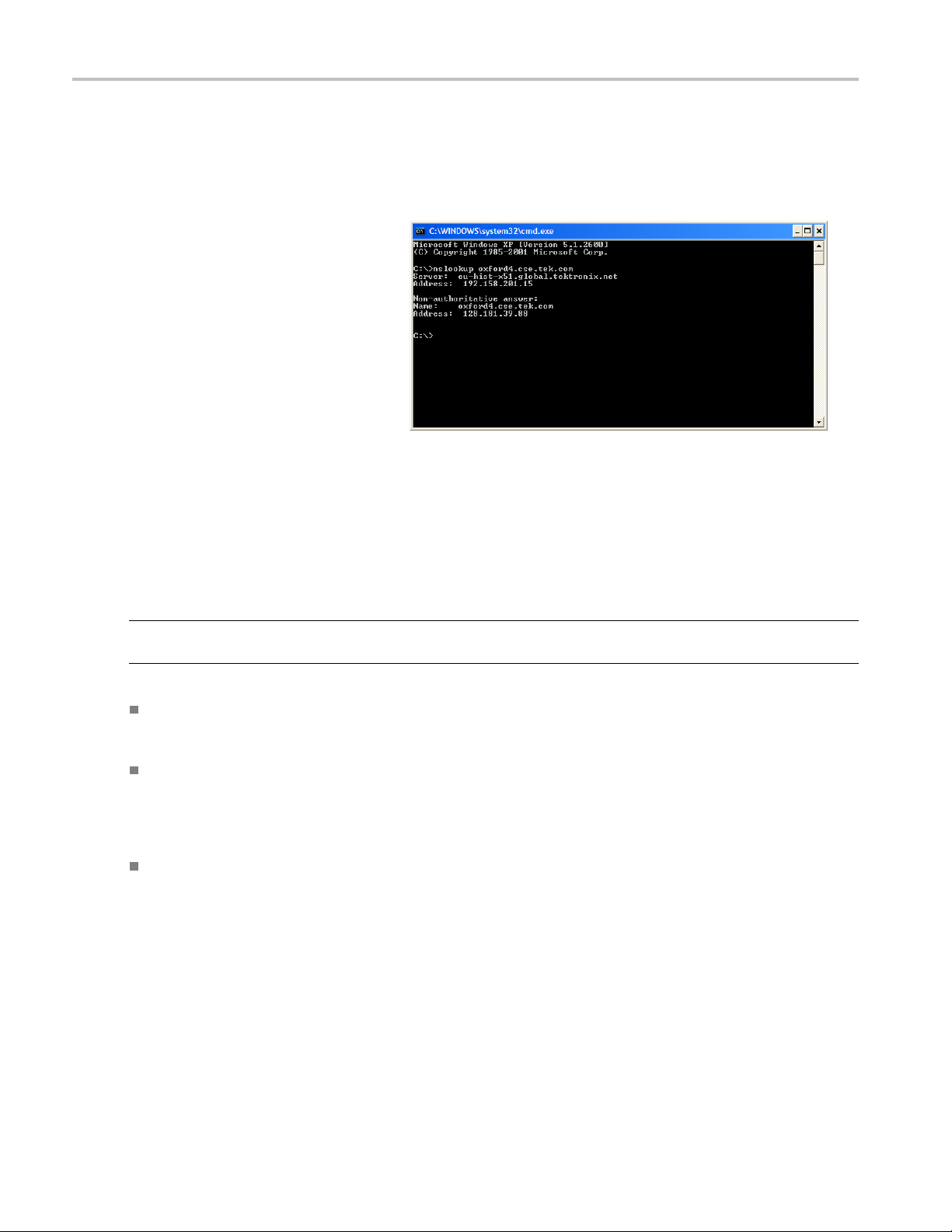
Finding IP addresses for devices on your network.
At times, you may need to find or confirm the IP address of a computer on your network (or find the network name if all you have is
an IP address). You may want to find this information to ensure that IP addresses and network names you use in the Hosts file are
correct. The u
1. Select Run from the Start menu. The
Run dialog bo
tility that will display this information is nslookup.exe. Use nslookup as described below:
x appears.
2. Enter one of t
Enter, where machineName or IPaddress
is the network name or IP address,
respective
to look up.
nslookup machineName
nslookup I
The network name and IP address of
the device you are trying to look up is
displayed
the IP address and network name of the
DNS server is also displayed.
Sources
If you need more information about network troubleshooting, some potential resources are listed below.
NOTE. These resources may provide you with more information. Most of this information is supplied a s is, with no warranty
as to its fitness, written or implied. The best source of network troubleshooting help is your network administrator.
Cisco Systems, Inc. – http://www.cisco.com/
he following and push
ly, of the device you are trying
Paddress
. If your network uses DNS,
of Network Information
This site is particularly useful for networks that use C isco devices.
Dulaney, E; Lawrence, S; Scrimger, R; Tilke, A ; White, J; Williams, R; Wolford, K. MCSE Training Guide: TCP/IP.
Indianapolis, IN. New Riders, 1998
This is a training guide for Microsoft Certified Systems E ngineer certification, and covers TCP/IP and network
troubleshooting.
Tayl o r, E . Network Troubleshooting Handbook. New York, NY. McGraw-Hill, 1999
Functional Check
Perform the performance verification procedure if you are operating the instrument for the first time (to verify that the
trument shipped without damage) or if you suspect that the instrument is not working properly.
ins
e procedure is located in the MTS400P Specifications and Performance Verification Technical Reference document.
Th
18 MTS400P Quick Start User Manual

Operation
Front Panel Controls and Connectors
Operation
CAUTION. If you power off the instrument using the On/Standby switch, the current instrument settings are not saved (this
operation corresponds to an emergency shutdown in Windows XP). To prevent data loss, use the Shutdown command
from the File menu to power off the instrument.
Table 4: Front panel controls and connectors
Control Function
On/Standby Switch Use this button to power on or off the instrument.
Stop Button This button performs the following functions:
If this button is p ressed while a stream data is being output, the data output stops.
If this button is pressed w hile the pretrigger portion is filled and the i nstrument
waits for a trigger event or the posttrigger portion is being recorded, the recorded
dataisstoredinafile.
Enter Button Use this button to execute the selected menu command or enable all setting changes
in a dialog box.
Cancel/Close Button
Use this button to cancel the selected operation. When any menu command list is
displayed, it closes the command list temporarily.
MTS400P Quick Start User Manual 19

Operation
Table 4: Front panel controls and connectors (cont.)
Control Function
Play/Pause Button This button performs the following functions:
If this button is pressed, the data output starts.
If this button is pressed while the Record screen is displayed, it switches to the
Play screen.
If this button is pressed while a stream data is being output, the data output
pauses. Press the button again to start the s tream output.
When an M-TMCC transport stream is selected, the MTS400P system outputs the
stream from the start packet in the super frame to the maximum number of packets
that can be looped as an integral multiple of the number of super frames. When an
ISDB-T transport stream is selected, the MTS400P system outputs the stream from
the start packet in the OFDM (Orthogonal Frequency Division Multiplexing) frame
to the maximum number of packets that can be looped as 2 X N of the number of
OFDM frames. If any of the transport streams within the ISDB-T transport stream
have different modulation parameters, select Non TS from the Packet Size command
in the Play menu.
The status indicator light in the button illuminates when stream data is being output.
The light blinks when the stream output pauses.
Record Button
This button performs the following functions:
Press this button to record the stream data that is being applied.
If this button is pressed while the Play screen is displayed, it switches to the
Record screen.
The status indicator light in the button blinks when a sync word is being detected, or
when the pretrigger portion of the stream data has been recorded.
HDD Access Indicator This indicator illuminates when the hard disk drive is in operation.
Menu Button
Arrow Buttons
Num Pad/Select Button
Tab button Use this button to select the numeric parameters in open dialog boxes.
USB Connectors Use the USB 2.0 connectors to connect the keyboard and mouse provided with the
Use this button to toggle the display of the menu command list on or off.
Use the arrow buttons to maneuver on the LCD display. For example, you can use
these buttons to move the Icon cursor or to move among the menu selections.
Use this button to enable or disable any setting changes in a dialog box. It is also
used to open the keypad, where you can enter numeric values for a text box.
When an ISDB-T file is selected in the Play screen or an ISDB-T signal is captured
in the Record screen, pressing this button causes the ISDB-T Information dialog
box to appear.
instrument for Windows operations. You can also connect other USB devices.
20 MTS400P Quick Start User Manual

Rear Panel Connectors
The rear panel connectors are described in the Installation section. (See page 6, Rear Panel Connectors.)
Software Applications
The MTS400P MPEG Test System provides a comprehensive and integrated suite of real-time and deferred (offline)
analysis too
elementary stream analyzers. Also included are an editor and a multiplexer to create stream content, and test and
error-stressing streams.
Note that some options might not be enabled. Detailed descriptions of all applications can be found in the M TS400 Series
MPEG Test S
ls. The tools include TS (transport stream) compliance, buffer, PES, MPEG2, and MPEG4 video and audio
ystem applications user manuals.
Operation
Standards
evolving DTV standards. New standards and proprietary tables can easily be implemented by loading Tektronix supplied
updates, or creating your own custom scripts.
Application
Analyzers
Transport Stream Compliance Analyzer (TSCA) – Real-time transport stream analysis with
user-selectable MPEG-2, DVB, ATSC and ISDB conformance tests. Shows transport structure, header
content
Transp
MPEG-2, DVB, ATSC and ISDB conformance tests. Shows transport structure, header contents,
hexadecimal packet contents, PCR timing/transport rate graphs and error message logs.
Packetized Elementary Stream (PES) Analyzer – PES analysis with selectable test options. Shows PES
progr
Transport Stream – System Target Decoder (T-STD) Buffer Analyzer analyzes program streams modeling
their behavior in, and their conformance to, the MPEG-2 T-STD Buffer Model. Includes a trace facility.
compliance is ensured though built-in customizable scripting, which supports a broad range of ratified and
s, hexadecimal packet contents, PCR timing /transport rate graphs and error message logs.
ort Stream Compliance Analyzer (TSCA) – Deferred transport stream analysis with user-selectable
am structure, header contents, packet contents, PTS/DTS timing graphs and analysis reports.
Desktop
1
Icon
entary Stream – Analyzer Elementary Stream analysis at video picture and audio level. This
Elem
includes vector graphs and macroblock picture quality.
MTS400P Quick Start User Manual 21

Operation
Application
Carousel Anal
yzer – Data analysis showing structure, bit rate, repetition rate, syntax and semantics of
data items.
Generators
Carousel Generator – Provides in-depth, off-line generation of MPE G-2, DVB transport streams
containing
a range of data broadcast protocols.
Multiplexer – Multiplexes table information and packetized elementary streams together to synthesize
new transport streams. A fine level of control is provided to allow nonconformances and test cases to be
specified f
or new transport streams.
Desktop
1
Icon
TS Editor
– Viewing and editing of transport stream packets, using a hexadecimal view of the packet
contents and semantic interpretation of the header. Provides facilities to remap PIDs, recalculate PCR
values and introduce PCR inaccuracies.
Players
MPEG Player – Records and plays MPEG-2 streams.
Utilities
Make Seamless Wizard – Guides the user through the process of creating an MPEG-2 file for use by
Player in continuously looped operation.
Stream
Stream Cutter – Extracts sections of MPEG-2 files to new files.
pt Pad – Enables users to create and modify System Information (SI) scripts.
Scri
TTS Utility – Converts time stamped transport streams to standard transport stream format.
1
If installed.
22 MTS400P Quick Start User Manual

Starting an Application
All applications are started from the Start > All Programs > Tektronix MTS400 menus.
The MTS400 Series system application user manuals provide full descriptions of all applications. The following table shows
the hierarchy of applications in the Start menu.
Menu hierarchy
Tektronix MTS400 >
Analyzers >
Generators >
Player >
Utilities >
OptionKey Wizard
Operation
Buffer Analyzer
Carousel Analyzer
ES Analyzer
PES Analyzer
TS Compliance Analyzer
Carousel Generator
Multiplexer
TS Editor
MPEG Player
Make Seamless Wizard
ScriptPad
Stream Cutter
TTS Utility
NOTE. Even though all applications are shown in the Start menu, you can only open those options that have been
purchased and licensed.
MTS400P Quick Start User Manual 23

Operation
Accessing Menu Commands
1. To access any m
open MTS400P application, do the
following:
Press the Menu button; the File
menu command
up (▲)ordown(▼) arrow button
to move through the command list.
Press the En
the selected command. Use the left
(◄)orright(►) arrow button to
select the d
Cancel/Close button to close the
command list temporarily.
2. Press the Menu button again to close
the menu co
NOTE. When you press the left arrow button
while the File menu is displayed or when you
press the
menu is displayed, the Windows Control
menu appears.
right arrow button while the Utility
enu command of an
list opens. Use the
ter button to execute
esired menu. Press the
mmand list.
Display States of the Menu Commands
The men
three display states:
u commands can have the following
A command followed by ► indicates
that a corresponding submenu will be
ayed after you press the Enter
displ
button or the right (►) arrow button.
A command followed by an ellipsis (...)
indicates that a corresponding dialog
ill open after you press the Enter
box w
button.
A command name by itself will be
executed after you press the Enter
ton.
but
24 MTS400P Quick Start User Manual
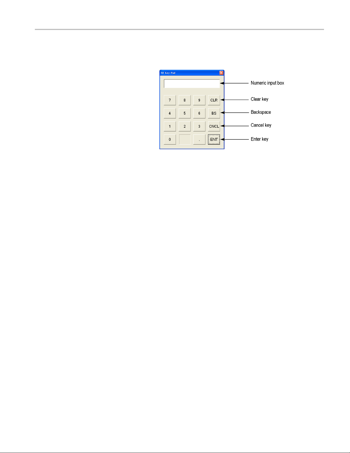
Entering Numeric Data
Using the Keypad
1. Open a dialog box in which you want to
change a parameter.
2. Press the Tab button repeatedly to select
(highlight) the numeric parameter that
you want to change in the open dialog
box.
3. Press the Num Pad/Select button to
open the keypad.
4. Press the Tab button or the arrow buttons
to move to the number you want to input
(when the keypad first opens, the dotted
line box is located on the ENT key).
5. Press the Num Pad/Select button. This
displays the selected number in the
numeric input box.
Operation
6. Repeat steps 4 and 5 to input the desired
parameter value.
7. Press the Enter button (or select the EN T
key and then press the Num Pad/Select
button). This saves the new value in
the numeric input box and closes the
keypad.
Using the Arrow Buttons
Perform the following procedure to change a value by using the arrow buttons:
1. Open the dialog box in which you want to change a parameter.
2. Press the Tab button repeatedly to select the numeric parameter that you want to change in the open dialog box.
3. Press the left (◄) arrow button to begin editing the parameter. This highlights the last digit.
4. Press the left (◄) or right (►) arrow button to m ove the highlighted cursor to the value you want to change.
5. Press the up (▲) or down (▼) arrow button to increase or decrease the value.
6. Repeat steps 4 and 5 to enter all of the desired values. To add a digit, press the left (◄) arrow button.
7. Press the Enter button to save the changed numeric values.
MTS400P Quick Start User Manual 25

Operation
Duplex Operation
The M TS400P system can be operated in duplex mode (ASI/SMPTE/DVB Parallel (SPI) only). For example, while the Player
is playing out a stream, the TS Compliance Analyzer can be analyzing a separate stream or, if the output is looped back to
the input, the output of the Player can be monitored by TS Compliance Analyzer (TSCA).
Setting Up Loopback
With loopback in operation you can:
Use the MPEG Player to play out a stream
Loop the instrument output back to the input
Monitor/analyze the incoming stream using the TSCA
Before starting:
Identify the stream to be played out (in this example, the sym1.mpg test stream is used).
Choose the output/input interface (ASI/SMPTE 310 or DVB SPI) and make the necessary connections (loop between the
connectors) at the rear of the instrument.
In the next example, the stream is looped back using the ASI interface and the stream is looped in the player (to play
continuously).
NOTE. You can choose either ASI or S P MTE310 to be supplied through the BNC connectors. The DVB S P I output is
enabled by default, whatever the settings are in the player. IP support is disabled by default.
MPEG player setup.
1. Open the MPEG Player: Start > Programs > Tektronix MTS400 > Player > MPEG Player.
2. Open a stream: File > Open… > sym1.mpg.
3. Make the following settings in the Play menu:
Packet size: 188
Update: On
Sync: TS Packet
Loop: On
Other: Standard: DVB
TSCA setup.
1. Open the TSCA: Start > Programs > Tektronix MTS400 > Analyzers > TS Compliance Analyzer.
2. In the start-up dialog box (Open Transport Stream…), select Change… in Stream Interpretation and select the DVB
base standard with no extensions. Close the Stream Interpretation dialog box.
3. Select Real-time Analysis and select ASI from the Interfaces drop-down list.
4. Select OK.
26 MTS400P Quick Start User Manual

Operation
Start the playout and analysis.
1. Return to the MPEG Player window and play the stream by selecting: Play > Start/Stop or use the toolbar button.
2. In the Player window, note that the status bar is now displayed and that playout has started.
3. Return to the TSCA window and note that analysis has started.
The MPE G Player is now playing out the sym1.mpg transport stream and, through the ASI input and output on the instrument
connector panel, the TSCA is monitoring and analyzing the stream.
For detailed descriptions of the MPEG Player and the TSCA, refer to the MTS400 Series Analyzer Applications User Manual.
MTS400P Quick Start User Manual 27

Procedures
Procedures
Using the MTS400 Series Applications
The applications in the MTS400 Series analysis toolset are targeted at a specific aspect or layer of a transport stream. The
following figure illust rates this principle in simplified form.
utorial will tell you how to open the application, how to analyse the test stream created earlier (testmux.mpg) and what
This t
results will be presented. It will not tell you how to interpret the results.
Transport Stream Compliance Analyzer
The TSCA provides real-time and off-line analysis of transport streams to check for compliance with a range of DTV
standards. Streams can be received through a r ange of RF and IPTV interfaces. A practical application of the TSCA is
described in Examine Stream Content with TSCA section. (See page 62, Examining Stream Content with the TSCA.)
28 MTS400P Quick Start User Manual

Procedures
PES Analyzer
The elementary streams, including video, audio, and ancillary data, are combined into a packetized elementary stream (PES).
The header associated with each PES packet in a transport stream is of particular interest, as it contains the decode and
presentation
picture freeze problems at the receiver in extreme cases.
timestamps (DTS and PTS) for the contained elementary streams. Errors in these timestamps may cause resets or
1. Open the PES A
Program > Tektronix MTS400 >
Analyzers > PES Analyzer.
2. Select File > New . Locate and open
a transport
stream created earlier, testmux.mpg.
The analysis progress is displayed in
the status
Program Structure view is displayed
when analysis is complete. In this
example yo
carries a single program, which contains
one video and one audio elementary
stream on
3. Select the video stream in the Program
Structure view; the maginifying glass icon
will indicate that it has been selected.
nalyzer. Start >
stream, for example, the
bar and the Event Log. The
u can see that the stream
PIDs 33 and 34 respectively.
4. Open each view option in the View menu,
that is, Event Log, Hex, Interpretation,
and PTS/DTS Timing. Each action opens
a new view in the PES Analyzer window.
It may be useful to tile the views in the
window using the Window > Tile option.
You can use the slider bar, above the
status bar, to navigate to any packet in
the PES stream. Packets are numbered
withinaPID,accordingtotheirposition
in the file. The slider bar displays the
packet number and the PID for the
current packet.
MTS400P Quick Start User Manual 29

Procedures
Packet Hex View
:
In this view, you can examine every byte in
the PES.
The four digit numbers in the left column
are the addres
ses of the firstbyteinthe
row.
The bytes displayed in magenta
represent the PES packet header.
You can view t
his as a graphical
representation in the Packet
Interpretation view.
30 MTS400P Quick Start User Manual

Procedures
Packet Interpr
This window interprets and displays a
graphical representation of the header of the
currently sel
header will vary depending on the packet
content.
PTS/DTS View:
This view shows a timing analysis of the
selected stream. The X-axis shows the
duration of the stream in seconds. The
Y-axis shows the differences between the
expected and actual DTS values. Vertical
blue lines show the difference between
the PTS and DTS for each access unit.
Additional access unit information is shown
in the side panel.
A compliant stream will show each DTS on
the 0 ms Y-axis; streams with errors usually
show a stepped graphical effect.
Select the toolbar magnifying glass and click
on the view to zoom in and out of the graph.
The slider at the bottom of this window
indicates where the displayed packets are in
relation to the rest of the file.
etation View:
ected packet. The size of the
MTS400P Quick Start User Manual 31

Procedures
T-STD Buffer Analyzer
The T-STD Buffer Analyzer models the behavior of the buffers in the hypothetical Transport Stream System Target Decoder, as
specified in ISO/IEC 13818-1. It can p rocess video, audio, and system c ontrol streams. The results of the analysis are displayed
as graphs of th
to the buffer model can include freeze frames and receiver resets.
e buffer capacity over time and a log of exceptions and noteworthy events. The consequences of non-conformance
1. Open the T-ST
> Program > Tektronix MTS400 >
Analyzers > Buffer Analyzer.
2. Review the configuration settings. View
>Settings.
In the System tab of the Settings
dialog box, select MPEG2 Packet
Interpretation and select P re-Scan
Packets All Packets.
D Buffer Analyzer. Start
32 MTS400P Quick Start User Manual

3. In the Video tab, select Buffer
Sizes, Automatic and Data Transfer,
Automatic.
4. In the Audio tab, select Buffer Size ,
Automatic
.
Procedures
5. Close the
Settings dialog box.
MTS400P Quick Start User Manual 33

Procedures
6. Select a file for analysis. File > N ew.
7. Locate and open an MPEG file. For
example, testmux.mpg, created in earlier
application e
Another file selection dialog box is
opened immediately. This is for you to
name and open
(BMR) file, which will hold the results of
subsequent analysis.
Accept the d
file.
The program performs initial analysis
to form a St
the mean transport rate. The stream
list displays all of the programs and
elementar
streams in the list are marked as
Unprocessed, because no analysis has
been perf
xamples.
a buffer model results
efault name and open the
ream List and calculate
y streams in the file. All
ormed on them in this session.
8. Select P
tranpsort stream context menu to start
processing the stream.
Analysi
status bar.
rocess Stream s from the
s progress is displayed in the
34 MTS400P Quick Start User Manual
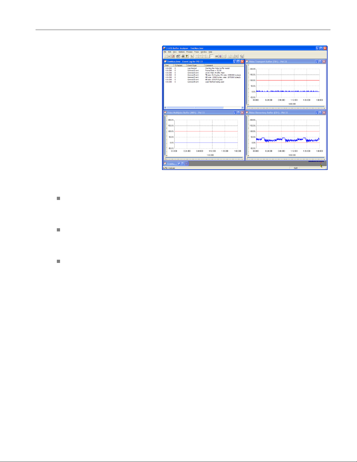
9. Highlight PID 33 and select All Buffers
from the context menu.
The following
for a video elementary stream: PID
Event Log, Video Transport Buffer, Video
Multiplex Bu
Buffer. (The Stream List window has
been minimized.)
10. Tile the resulting windows: Window >
Tile.
PID Event Log:
You can ope
log (View > Global Event Log) that displays
high level events occurring in the initial
analysis p
> PID Event Log) that displays events for
each processed PID.
In the following buffer graph views:
windows will be displayed
ffer, and Video Elementary
n two event logs: a global event
rocess and a PID event log (View
Procedures
Use the toolbar magnifying glass icons
to zoom i
Zoom value can be reset using the Reset
Zoom toolbar button.
All open graphs can be viewed and
manipu
> Synchronize Views to synchronize all
views with the currently selected view.
Red y-axis lines indicate the 0% and
100% l
Video
In this view, for video streams, you can see
the results of modeling a multiplex buffer.
For a
can see the results for the main buffer. The
title bar shows the stream type.
Video Transport Buffer:
s view shows results of modeling the
Thi
transport buffer for video, audio, or system
control streams.
n and out of the selected graph.
lated separately. Use the Options
imits.
Multiplex / Main Buffer:
udio and system control streams, you
MTS400P Quick Start User Manual 35

Procedures
Video Elementary Buffer:
This view shows only applicable video
elementary st
reams.
11. Select View >
log.
The trace log can help you analyze the
message log
Analyzer. These logs may be useful
for in-depth analysis of the internal
processing
stream type. The trace view has filtering
capabilities that allow you to focus on
message ty
Trace to display the trace
s produced by the Buffer
, particularly for the video
pes of particular interest.
36 MTS400P Quick Start User Manual

Procedures
Elementary Stream Analyzer
The ES Analyzer checks for compliance of CODECs to either next generation VC-1, AVC/H.264 and MPEG-4 standards
or legacy MPEG-2 and H.263. Audio decode and waveform display of MPEG-2 audio (ISO/IEC 13818 parts 3 and 7),
AC-3 and MPEG-4 AAC are also supported.
ES Analyzer is a complex application which you can use to analyze many aspects of video and audio streams. For this reason,
the following procedure shows you how to access some of the analysis screens; detailed explanation of their content and meaning
can be found in the MTS400 Series Analyzer Application U ser Manual.
1. Open the ES Analyzer. Start > Program
> Tektronix MTS400 > Analyzers > ES
Analyzer.
2. Select a file for analysis. File > New.
Locate and open an MPEG file. For
example, testmux.mpg, created in earlier
application examples.
3. Click o
n each successive node in the
navigation window until the GOP (Group
of Pictures) is highlighted in the Program
1 / PES (
PID 33), MPEG 2 Video branch.
MTS400P Quick Start User Manual 37

Procedures
4. Select the Picture Player tab. Note that
the Picture Player remote control is
displayed.
5. Click the Show
expand the control bar. The extra
information shows the position in the file
of the displa
is shown in the status bar.
6. Start playing the stream by clicking the
play butt
If you stop the playout, you can select the
other GOP tabs (GOP and Picture, Slice
and MB),
of that frame.
7. For exa
mple, s elect the Picture Display
on the Slice and MB tab. The picture will
correspond to the picture in the Picture
.
Player
Information button to
yed picture; more information
on on the control bar.
and examine the characteristics
8. Click S
how MV (motion vectors) on the
right of the picture display. For B and
P frames, the motion vectors will be
ayed as coloured arrows overlaying
displ
the picture.
38 MTS400P Quick Start User Manual

Procedures
Additionally,
characteristics of any of the macroblocks
that make up the picture by hovering the
mouse over a pi
9. Use the Pre
buttons to move backward and forwards
in the stream and compare the motion
vectors.
You can examine the characteristics of
the audio stream in a similar manner.
you can see the
cture macroblock.
vious Frame and Next Frame
10. Click on each s uccessive node in the
navigation window until the GOP (Group
of Pictures) is highlighted in the Program
1/PES (PID 34), MPEG 1 Audio b ranch.
Use the audio control bar to review
the audio track. You will need to use
headphones to hear the output.
MTS400P Quick Start User Manual 39
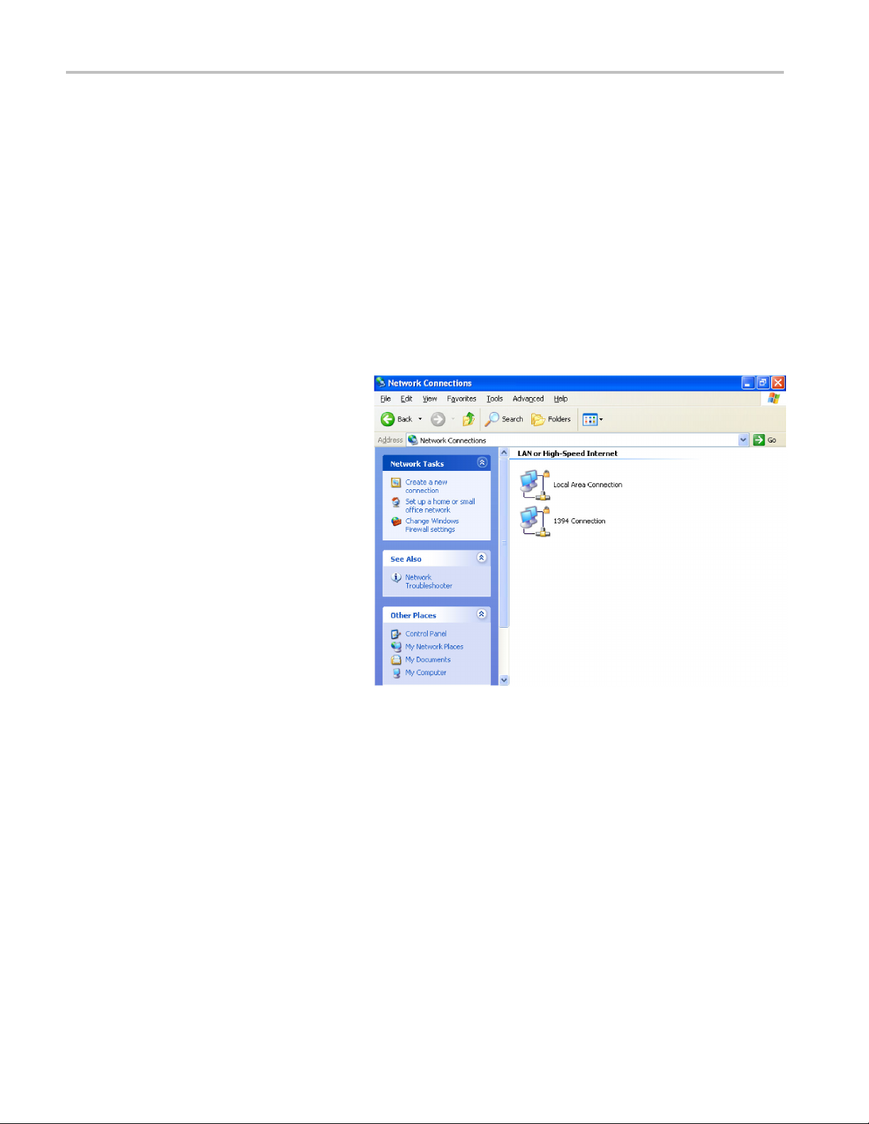
Procedures
Setting Ethernet Network Parameters
Perform the following procedure to set the network parameters for the MTS400P system:
1. Connect the keyboard and the mouse
provided with the instrument to the USB
connectors on the front panel. You can
connect them to either of the c onnectors.
2. Select File > Minimize or File > Exit to
close the Play (or Record) screen. The
Windows XP desktop appears.
3. Select Settings > Control Panel from
the Start menu. The Control Panel
window appears.
4. Double-click the Network Connections
icon in the window. The Network
Connections window appears.
40 MTS400P Quick Start User Manual
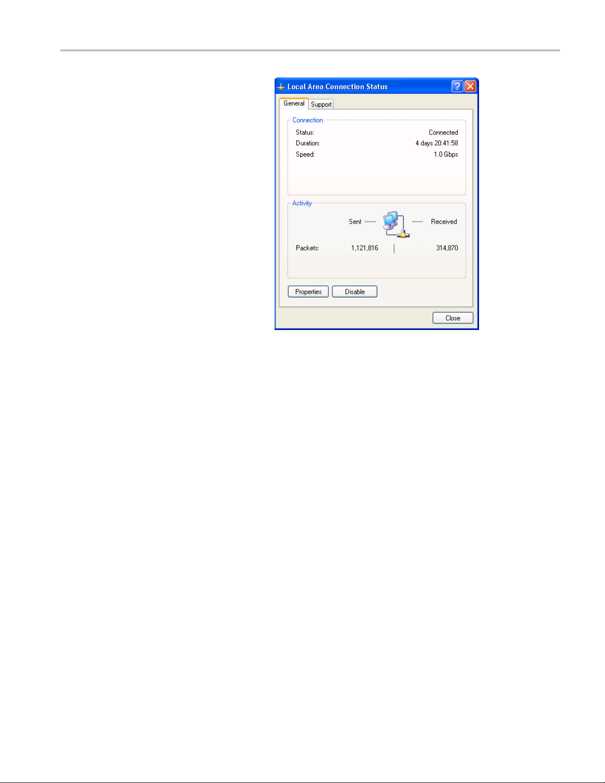
5. Double-click the Local Area Connection
icon. The Local Area Connection Status
dialog box app
ears.
Procedures
MTS400P Quick Start User Manual 41

Procedures
6. Click the Properties button. The Local
Area Connection Properties dialog box
appears.
7. In the network component field, click
Internet
Protocol (TCP/IP).
8. Click the
Properties button.
The settings in the dialog box depend on whether a DHCP (Dynamic Host Configuration P rotocol) server is in the network
connected to the MTS400P system.
42 MTS400P Quick Start User Manual

Procedures
When the DHCP Server Is in the Network
If the DHCP server is in the network, perform steps 9 and 10, otherwise skip to step 11.
9. In the dialog box, select Obtain an IP address automatically and Obtain DNS server address automatically.
10. Click the OK button.
The MTS400P accesses the DHCP server and obtains the addresses automatically when connected to the network.
Refer to the user documentation supplied with your server OS for detailed information about DHCP server functions.
NOTE. In some network environments, the MTS400P system may not be able to obtain the IP address automatically from a
DHCP server. In this case, you need to enter the appropriate address value in each submenu item.
When the DHCP Server Is Not in the Network
If the DHCP server is not in the network, perform the following procedure to set the network parameters.
11. If you connect the MTS400P system directly to a single PC:
In the dialog box, select Use the following IP address.
Set the IP address parameter to be the same IP address as the PC’s address except for the last number. The last
number m
ust be different from the last number in the PC’s IP address.
Set the S
the PC does not have a net mask.
You do not need to enter a Default gateway if you are directly connected to a single PC.
12. If you connect the MTS400P system to your local Ethernet network:
In the dialog box, select Use the following IP address.
Ask your local network administrator and set the appropriate addresses.
CAUTION. To prevent communication conflicts on your Ethernet network, ask your local network administrator for the correct
rs to enter in the dialog box if you connect the MTS400P system to your local Ethernet network.
numbe
13. Verify the Ethernet connection by using a ping command from the PC. (See page 16, Pinging a host machine.)
ubnet mask parameter to be the same net mask (subnet mask) used by the PC. Do not enter a number if
MTS400P Quick Start User Manual 43

Application Exa
mples
Application Examples
This section prov ides the following application examples:
Creating, viewing, and analyzing a transport stream, including:
Using the Multiplexer application to create a new transport stream
Setting up FlexVuPlus™ in the Transport Stream Compliance Analyzer (TSCA) application
Examining the content of the created stream using the TSCA application
Inspecting the created stream using the PES Analyzer, T-STD Buffer Analyzer, and ES Analyzer applications
Creating, Viewing, and Analyzing a Transport Stream
The following application example describes how you can create a new transport stream and examine it for errors.
Create a n
In this section of the application example, you will create a new transport stream using the MTS400 Series Multiplexer application.
You will i
1. Open the Multiplexer application. Start
>Progra
Generators > Multiplexer.
ew stream using the multiplexer
ntroduce one error so that you will be able to observe it in a later section of the application example.
ms > Tektronix MTS400 >
44 MTS400P Quick Start User Manual

2. Select View > Interpretation.
3. In the Stream Interpretation dialog box,
ensure that the selected Base Standard
is DVB and that
the Region is None.
Application Exa
mples
4. Select OK to c
Interpretation dialog box.
5. Select File > New.
6. In the Navigator window, highlight the
Transpor
Properties from the context menu.
lose the Stream
t Stream node and select
7. In the Stream Properties dialog box,
enter a bit rate of 24.128 Mbit/s
and a fixed duration of two minutes
(120 seconds). Select OK.
Note that the two values are displayed in
the status bar.
MTS400P Quick Start User Manual 45
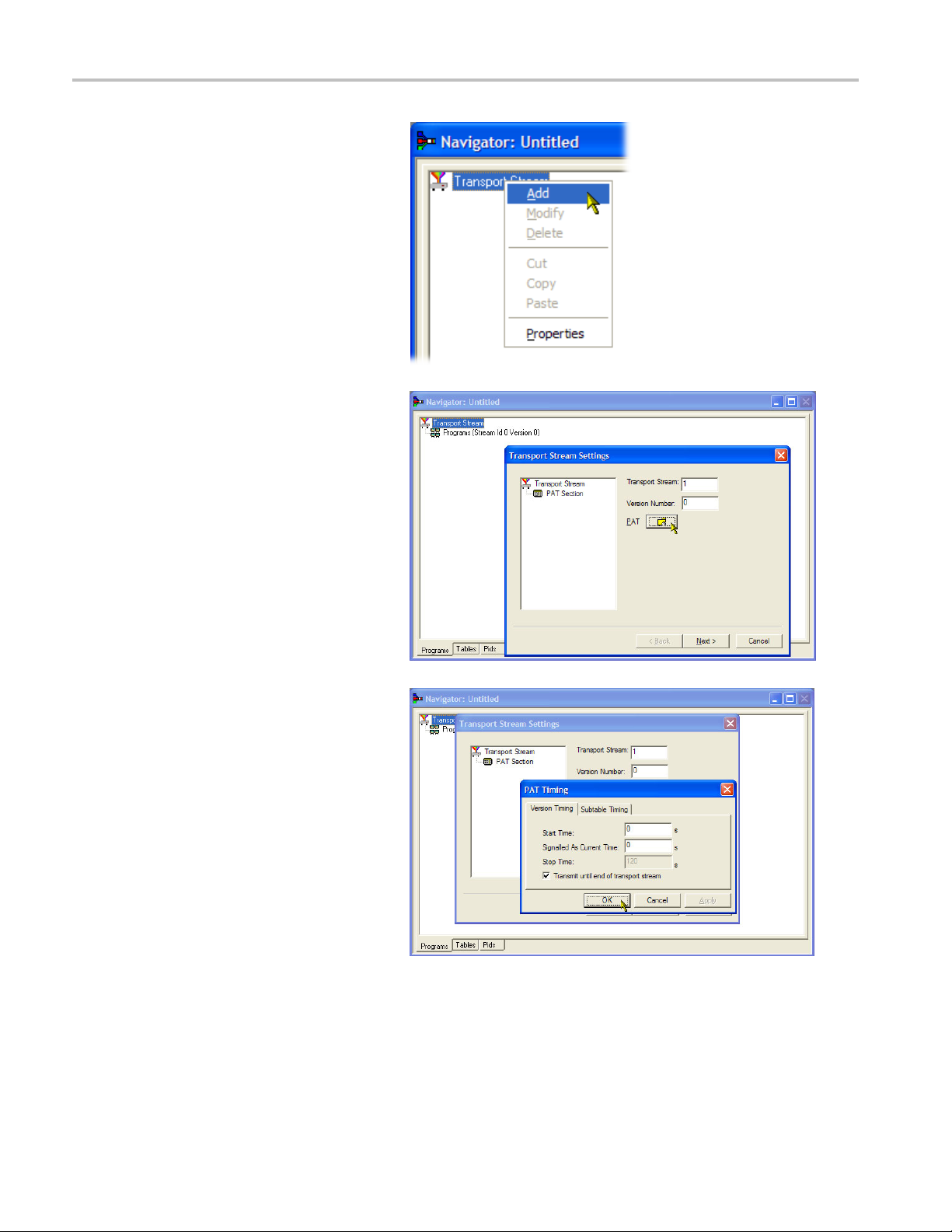
Application Exa
mples
8. In the Navigato
Transport Stream node and select Add
from the context menu.
9. In the Transport Stream Settings dialog
box, enter 1 as the Transport Stream
identity.
10. Select th
Table) folder icon button to open the PAT
Timing dialog box.
r window, highlight the
e PAT (Program Allocation
In the Version Timing tab window, note
that the PAT timing Start time (0 s) and
Stop time (120 s) mean that the PAT will
be transmitted for the stream duration.
11. Select OK to close the PAT Timing dialo g
box.
12. In the Transport Stream Settings dialog
box, select Next.
46 MTS400P Quick Start User Manual

13. In the Optional Tables for the Stream
dialog box, select the TDT (Time and
Date Table) ch
TDT folder icon button.
In the TDT Timing dialog box, confirm
that the Start Time is zero and the
Stop Time is the same as the duration
previously set.
Note that the duration may have been
adjusted by an insignificant amount. In
this example, the set duration of 120 s is
now displayed as 119.99999049.
eck box and select the
Application Exa
mples
14. Enter a Cycle Time of 1000 ms.
15. Select OK to close the TDT Timing
dialog box.
16. In the
Optional Tables for the Stream
dialog box, select the NIT (Network
Information Table) check box and select
T Settings button.
the NI
MTS400P Quick Start User Manual 47

Application Exa
17. In the Set up the NIT dialog box, enter
mples
the Network Id 1234 and the Network
Name Tek _ tes t
.
18. Set the Origin
and select Terrestrial from the Delivery
System drop-down list.
19. Select the Delivery System Settings
button.
20. In the Terrestrial Settings dialog
box, enter 0x123456 in the Centre
Frequency field.
21. Select 2 (64-QAM) from the Constellation
drop-down list.
22. Select 4 (non-hierarchical, in-depth
interleaver) from the Hierarchy
Information drop-down list.
23. Select 1(8kmode)from the
Transmission Mode drop-down
list.
al Network identity to 2
24. Select OK to close the Terrestrial
Settings dialog box.
25. Select OK to close the Set up the NIT
dialog box.
26. In the Optional Tables for the Stream
dialog box, select Next and display
Transport Wizard Complete dialog box.
The transport stream set up is complete.
Now you need to add some content in
the form of video and audio elementary
streams.
48 MTS400P Quick Start User Manual

Application Exa
mples
Elementary stream acquisition.
For this example, you need to add a video and an audio elementary stream to the transport stream that you have created. You can
extract suitable streams from one of the sample transport streams supplied with the MTS400 installation. The stream suggested is
Sym1.mpg; thi
1. Open a second instance of the
multiplexer
Tektronix MTS400 > Generators >
Multiplexer.
2. Select F ile > Open.
3. In the Set MPEG File to Edit dialog box,
locate and o
s is available on the E: drive of your MTS400.
. Start > Programs >
pen sym1.mpg.
4. Expand the program 1 node and the
dependent Elementary Streams node.
5. Highlight the PID 110 node. This PID is
carrying an MPEG-2 video elementary
stream. The es file extension will be
added automatically.
6. Select Export Elementary Stream in
the context menu.
7. In the Save As dialog box, enter a file
name (Sym1pid110.es) and save the file
to a suitable location.
8. Repeat the action for PID120. Name the
ym1pid120.es.
file S
ect File > Exit to close this instance
9. Sel
of the Mux.
This completes the extraction of the
eo and audio elementary streams.
vid
You can continue with the multiplexing
task.
MTS400P Quick Start User Manual 49
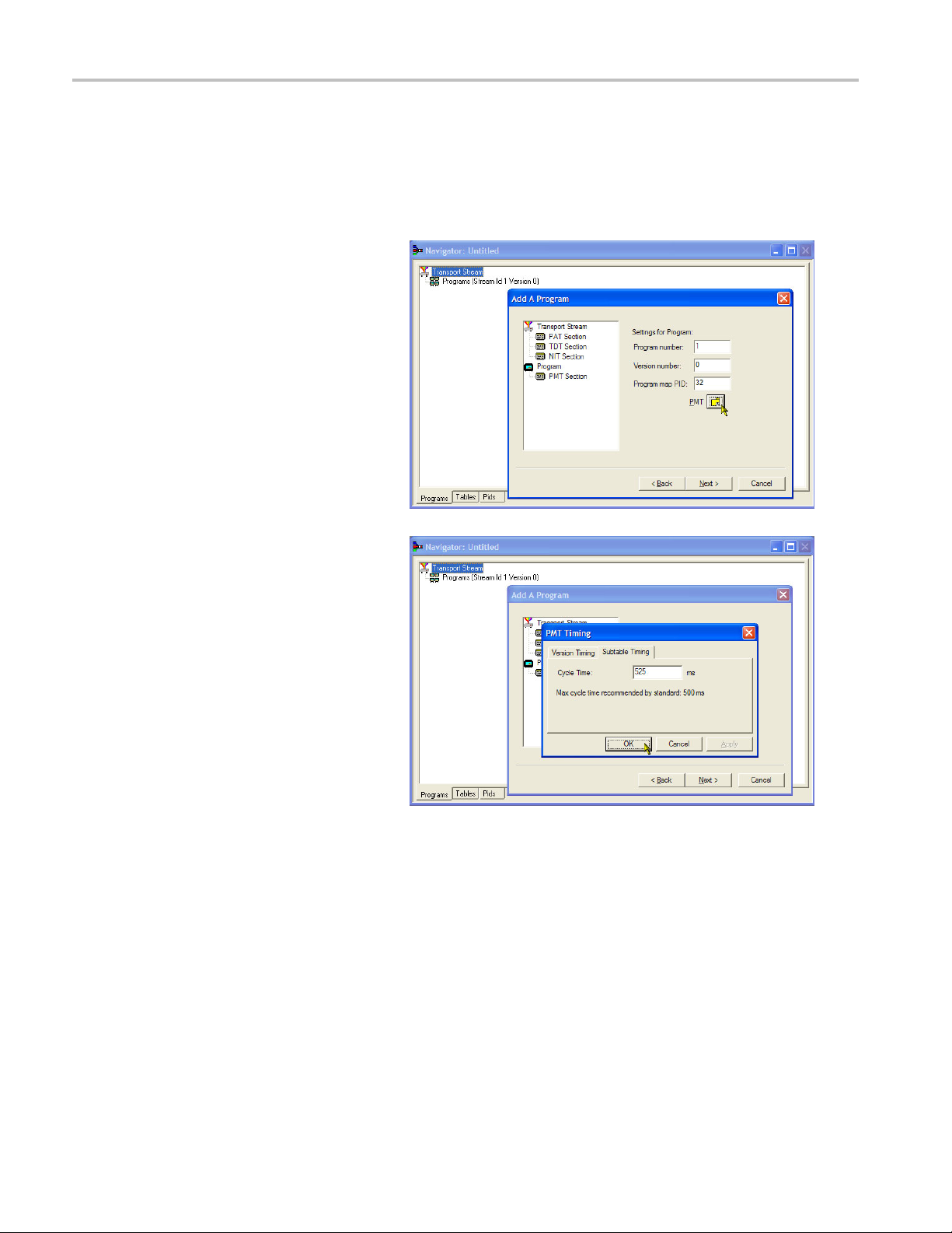
Application Exa
Add elementary streams.
Now you can return to the original multiplexer i nstance and add the elementary streams that you have just created.
1. Ensure that Add a Program Wizard is
2. In the Add a Program dialog box, enter
mples
checked and se
1 as the progr
lect Next. See step 26.
am number.
3. In the PMT Timing dialog box, select the
Subtable Timing tab.
The subtable timing cycle time is the
period over which a table is repeated in
the stream. The maximum cycle time for
the PMT in the DVB standard is 500 ms.
4. For this example stream, set the
CycleTime to 525 ms.
5. Select OK to close the PMT Timing
dialog box.
6. In the Add a Program dialog box, select
Next.
50 MTS400P Quick Start User Manual

7. In the Add Service Description dialog
box, select the Add Service Description
check box.
Application Exa
mples
8. Enter a Servic
example, Tek Broadcasting.
9. Enter a Service Nam e, for example,
Tek1.
10. Enter a Service Type, for example, 1
(0x1) (digi
11. Select Next
12. In the Add the Program Content
dialog box, select Add to add a video
elementary stream.
e Provider Name,for
tal television service).
.
13. In the Add Program Stream dialog box,
t 2 (0x02) (MPEG-2 Video) from
selec
the Stream Type drop-down l ist.
14. Ensure that the Source tab is selected.
15. Enter a File Name, or use Browse to
locate the video elementary stream
iously set up (Sym1pid110.es).
prev
16. Sele
ct MPEG-2 video from the File type
drop-down list. Note that the file bit rate
has been entered automatically.
MTS400P Quick Start User Manual 51

Application Exa
17. Select the PCR tab. Ensure that the
mples
Select the Timing tab. Note that the
elementary stream is going to run for the
length of the s
is, 120 s.
Carry PCR check box is selected.
tream previously set, that
18. Selec
19. In the Add Program Content dialog
20. Sele
21. In the Add Program Stream dialog box,
22. EnteraFileName,orusethe
t OK to close the Add Program
Stream dialog box.
box, select Add again to add an audio
entary stream.
elem
ct 3 (0x03) (MPEG -1 Audio) from
the Stream Type drop-down list.
ensure that the Source tab is selected.
wse button to locate the audio
Bro
elementary stream previously set up
(Sym1pid120.es).
52 MTS400P Quick Start User Manual
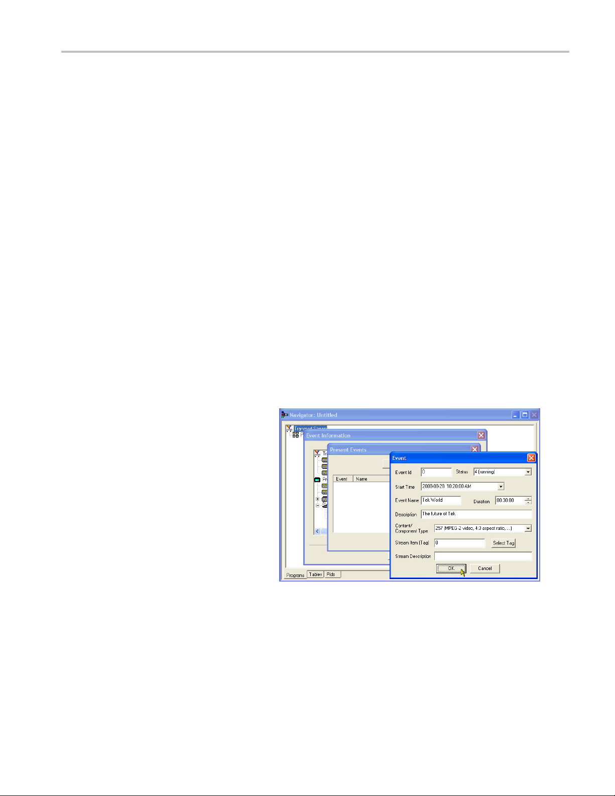
23. Select MPEG-2 audio from the File type
drop-down list. Note that the file bit rate
has been enter
ed automatically.
Application Exa
mples
24. Select the Tim
elementary stream is going to run for the
length of the stream previously set, that
is, 120 s.
25. Select the PC
Carry PCR check box is cleared.
26. Enter 33 in the PCR PID field. This is the
PID that will carry the P CR information –
also the vi
27. Select OK t
Stream dialog box.
28. Select Next.
29. In the Event Information dialog box,
select the E vent Information Tables (EIT)
check bo
30. Ensure t
selected.
31. Select Present Settings.
32. In the P
select Add to set up the present event
information, that is, the time of this
cast. In the Event dialog box,
broad
select 4 (running) from the Status
drop-down list.
ing tab. Note that the
R tab. Ensure that the
deo es, Carry PCR.
o close the Add Program
x.
hat the Present check box is
resent Events dialog box,
33. Set the Start Time to 2008-08-28
0:00 AM.
10:2
You can change the time and date
by highlighting the individual field and
ring the required value.
ente
MTS400P Quick Start User Manual 53

Application Exa
34. Enter an Event Name, for example, Tek
35. Enter a Description, for example, The
mples
World.
future of Tek.
36. Enter a Durat
(00:30:00).
37. Select 257 (MPEG-2 video, 4:3 aspect
ratio, ...) from the Content/Component
Type drop-d
38. Select OK to
39. Select OK t
dialog box.
40. Ensure th
selected.
41. Select Following Settings.
42. Select Add to set up the following event
information, that is, the event following
the pres
43. In the Ev
Event Id field.
44. Select 1 (not running) from the Status
drop-down list.
45. Set the Start Time to 2008-08-28
:00 AM.
10:50
ion, for example, 30m
own list.
close the Event dialog box.
o close the Present Events
at the Following check box is
ent event.
ent dialog box, enter 1 in the
46. Enter
47. Enter a Description of the event, for
48. Enter a Duration, for example, 30 m
49. Sel
50. Select OK to close the Event dialog box.
51. Select OK to close the Following Events
52.S
54 MTS400P Quick Start User Manual
an Event Name, for example, Tek
News.
example, All the latest news from Tek.
:00:00).
(01
ect 257 (MPEG-2 video, 4:3 aspect
ratio, ...) from the Content/Component
Type drop-down list.
ialog box.
d
elect Next.

53. In the Program Complete dialog box,
select Finish.
You have finished creating the structure
and content of the proposed transport
stream. You can now make a couple of
checks to ensure that the stream will compile
successfully.
Application Exa
mples
54. Select View > Available Bitrate.
In the Available Bitrate graph, note that
the bit rate remains within the required
bitrate, that is, 124.128 Mbps.
You can examine the bit rate at any point
on the graph, by clicking a point ans
reading the values from the adjacent
table.
55. Close the Available Bitrate graph.
56. Select Multiplex > Start to start the
multiplex.
MTS400P Quick Start User Manual 55

Application Exa
57. In the Set TS Output File dialog box,
58. Select File > Export.
59. In the Export File dialog box, enter a
mples
enter a name for the new multiplexed
transport str
TestMux.mpg.
Watch the right side of the Status bar for
the multiple
bar may be hidden if the window is too
small horizontally.
The elementa
information have now been multiplexed
together to form the transport stream,
TestMux.mp
It is a good idea to save the structure of
the multiplex, so that it can be recalled
and more in
required.
name for the multiplex structure file,
for exam
muxml extension.
eam, for example,
xing progress; the progress
ry streams and structural
g.
formation added to it as
ple, TestMux.muxml. Note the
60. Using File > Import, the multiplex
structure file can be reopened at any
add elementary streams or
time to
structural information.
56 MTS400P Quick Start User Manual

Application Exa
Setting up the FlexVuPlus™ display
Using FlexVuPlus, you can select up to four views from the analysis detail views to be displayed together to facilitate basic
transport stream monitoring or more detailed diagnostic monitoring.
For this exercise, close each of the currently
displayed FlexVuPlus panels by clicking the
X in the top ri
This is not necessary, but it may help y ou
visualize the following procedure more easily
as each panel
of the four FlexVuPlus panels are numbered.
ght corner of each panel.
is populated. Note that each
mples
Set up panel 1
1. Select the Analysis tab and then the
Tests tab.
In the top right corner of all detail views
is a FlexVuPlus panel select button.
You can use this button to display a
replica of the detail view in the selected
FlexVuPlus panel.
2. In the Test Summary view, use the
FlexVuPlus panel select button to
replicate the view in panel 1.
MTS400P Quick Start User Manual 57

Application Exa
mples
3. The FlexVuPlus
display now contains the
Test Summary view in panel 1.
Set up panel 2.
4. Select the Analysis tab and then the
Programs tab.
5. In the Thumbnails view, use the
FlexVuPlus panel select button to
replicate the view in panel 2.
58 MTS400P Quick Start User Manual

Application Exa
mples
6. The FlexVuPlus
display now contains the
Thumbnail view in panel 2.
Set up panel 3.
7. Select the Analysis tab and then the
Tests tab.
8. In the Test Failures view, use the
FlexVuPlus panel select button to
replicate the view in panel 3.
MTS400P Quick Start User Manual 59

Application Exa
mples
9. The FlexVuPlus
display now contains the
Test Failures view in panel 3.
Since only three panels are used in this
example, you can expand the thumbnails
view to fill the right side of FlexVuPlus™.
You can expand panel 2 vertically by
selecting the panel expand button.
60 MTS400P Quick Start User Manual

(Similarly, you can expand panels
horizontally using the horizontal panel
expand button
.)
Application Exa
mples
10. Expand panel
2 to display the complete
FlexVuPlus basic monitoring view.
To summarize, in this view you can immediately see the following:
In the Tests Summary v iew (FlexVuPlus panel 1), which tests have failed.
In the Test Failures view (FlexVuPlus panel 3), which tests have failed most recently.
In the Thumbnails view (FlexVuPlus panel 2), which elementary streams are currently carrying video content.
MTS400P Quick Start User Manual 61

Application Exa
Examining Stream Content with the TSCA
The example transport stream created in the previous applications, testmux.mpg, will be examined off-line using the Transport
Stream Compliance Analyzer.
1. Open Transport Stream Compliance
mples
Analyzer. File > Program > Tektronix
MTS400 > Anal
Analyzer.
In the TSCA toolbar, select Open File.
You may need to close the Select
Real-time I
you can select the off-line analysis set
up.
In the Open
ensure that the Base Standard is DVB
and the Region is No Extensions.
Locate an
tetsmux.mpg.
Ensure that in the Advanced Settings
pane, the
Timestamp Settings are as shown.
yzers > TS Compliance
nterface dialog box, before
File Analysis dialog box,
d select the example stream,
Stream Bit Rate and the
The analysis will take a moment to
complete.
62 MTS400P Quick Start User Manual

2. Select the Analysis tabtodisplaythe
navigation and related views.
3. Select the Program s tab and expand the
nodes in the na
the plus symbols.
In the detail views, ensure that the
Summary view
displayed.
The Transport Stream node and the
Program nod
that an error has occurred in the stream
and is still active.
4. Highlight the Transport Stream node.
In the Test
101 290 tab, note that test 1.5.a PMT is
indicating an error, that is, the associated
LED is red.
5. Highlight test 1.5.a PMT and select
View this
context menu.
vigation view by clicking
and the Tests view are
e are both red. This shows
s Summary detail view, TR
test in the Tests tree from the
Application Exa
mples
The Test
navigation view is expanded to show the
failed test. The detail view shows any
PIDs as
(none in this example) and the event
log filtered to show only events for the
highli
Examine the log entries for error
information. Note that the error reports
refer
the PMT section repetition rate; 525 ms
was the value set in the example stream
creat
s tab views are displayed. The
sociated with the highlighted test
ghted test.
to a duration of 525 ms. This is
ed earlier.
MTS400P Quick Start User Manual 63

Application Exa
mples
6. In the navigati
1.5 PMT (Timer) test and select Edit
Parameters from the context menu.
7. In the Edit Parameters dialog box,
note that for t
section max. repetition interval is
set to 500 ms. Since the repetition rate
found in this
(525 ms), it is being reported as an error.
However, by examining the maximum
and minimum
the Edit Parameters dialog box (hover
the mouse pointer over the value field
and refer to
the rate of 525 ms is within the range
recommended by the DVB standard,
40 ms to 250
IP Stress Test
Perform the following steps to set up and to demonstrate the IP stress generation capabilities of the MTS400P system
using a portable PC.
on view, highlight the
his s tream the PMT
stream exceeds this value
repetition rates shown in
the tootip), you can see that
00 ms.
NOTE. You can perform the IP stress test for the instruments only if the TSCA option is installed on the MTS400P system.
Set Up
1. Connect the Ethernet cable to the LAN
port of the portable PC and the LAN port
on the MTS400P system.
2. Power on both the MTS400P system and
the portable P C.
3. Start the MPEG Player application on
the MTS400P system. Ensure that the
security dongle is attached to the portable
PC and start the TSCA application.
4. In the MPEG Player application, select
Play > Interface >IP.
5. Select IP > Configuration.
Note the Source IP address and ensure
that the Transmission Mode is set to
Multicast.
64 MTS400P Quick Start User Manual
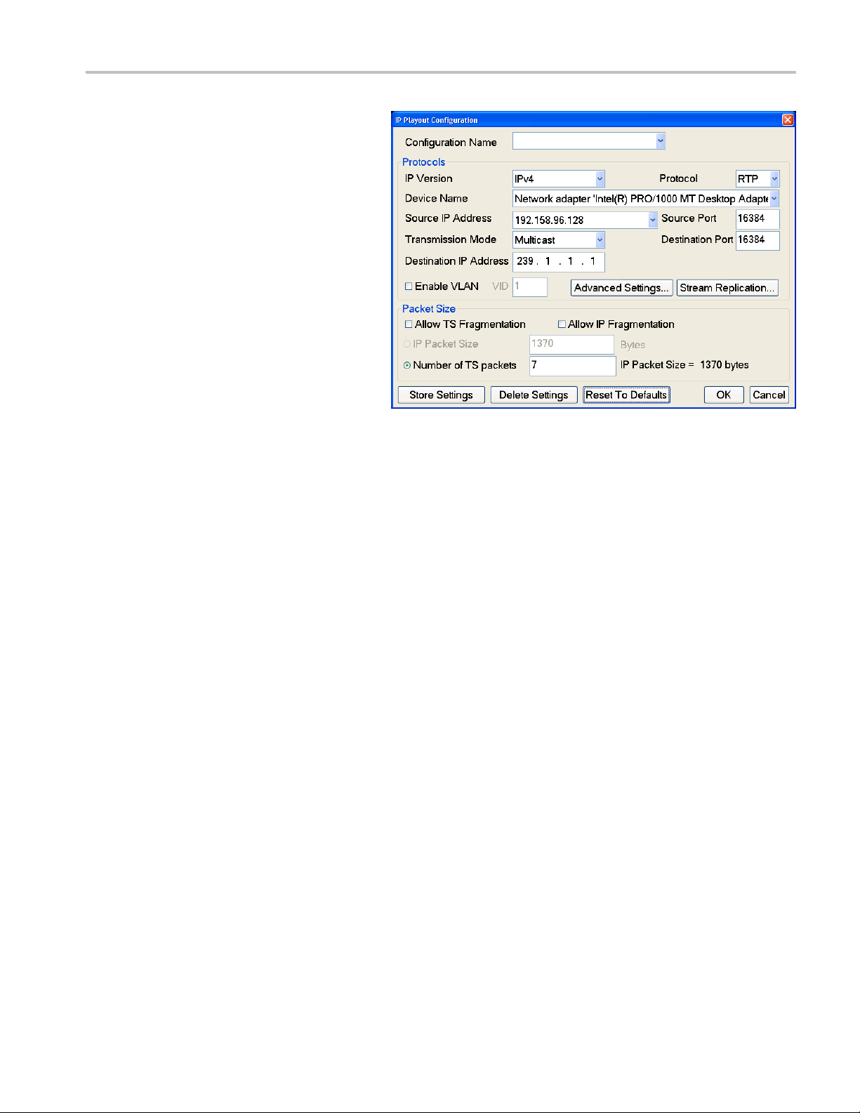
6. Select OK on the MTS400P configuration
menu and select a test stream file from
the D: drive.
Application Exa
mples
7. Press the
PLAY button on the MTS400P
system to start playing the selected
stream file.
8. Open the TSCA application and verify
that the
Stream Interpretation is set
appropriately for the demo.
MTS400P Quick Start User Manual 65

Application Exa
9. In the TSCA, Select Real-time, and then
10. In the Browser for UDP flow dialog box,
mples
select Browse.
A single flow sh
source IP address as the MTS400P
Configuration window showed. This
means TSCA ca
traffic.
select the flow and click OK.ClickOK in
the Selec
The real time analysis of the stream will
be displayed in TSCA. If the stream has
no error
is green.
ould be seen with same
n see the MTS400P
t Real time Interface dialog box.
s, then everything on the T SCA
66 MTS400P Quick Start User Manual
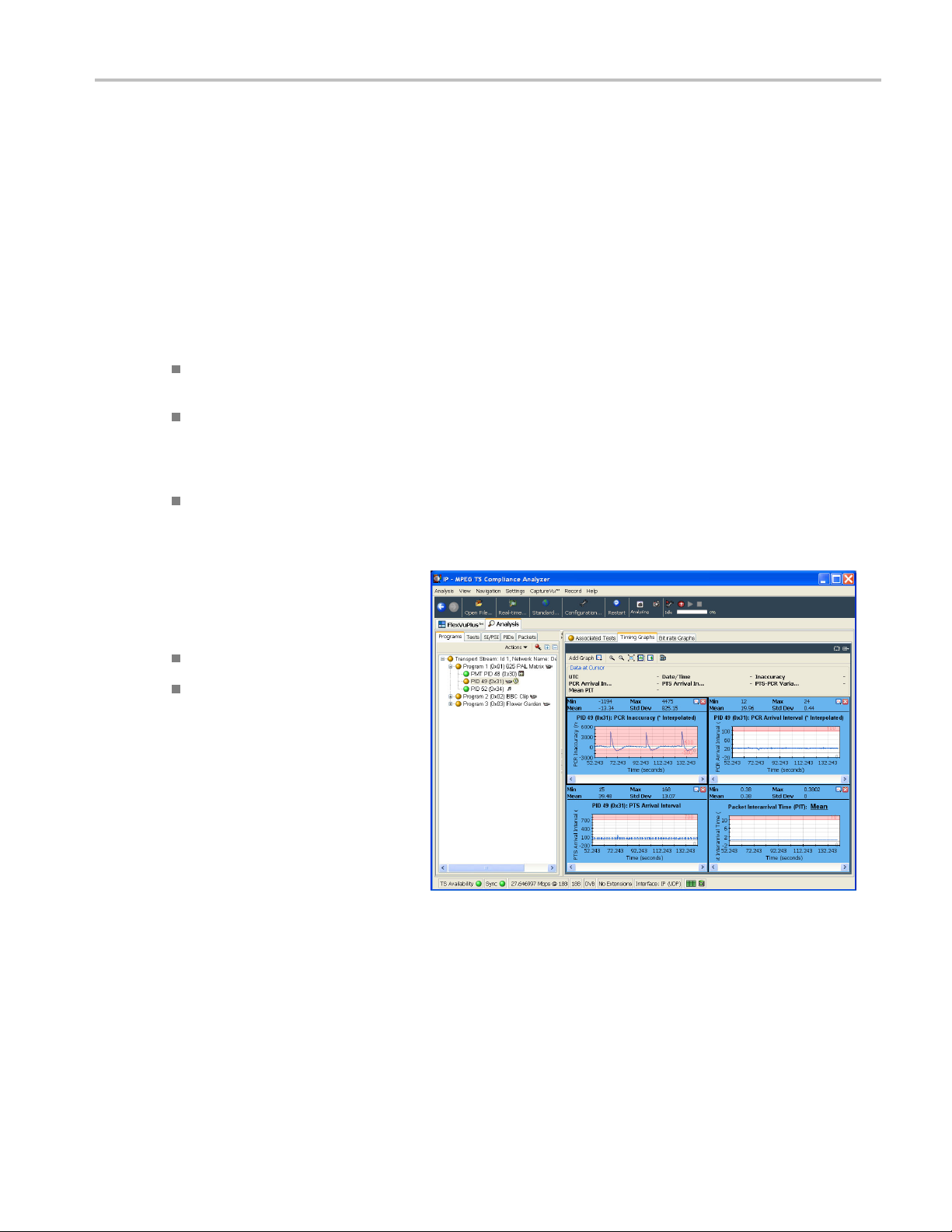
Outputting the IP Stress Test (Multicast)
This procedure involves playing the MPEG Player in IP mode and analyzing the output stream using a TSCA.
Application Exa
mples
1. In the TSCA, se
select the Play button under one of the
thumbnails. This will start the VLC to
show decoded
This is analogous to the way an STB
would decode the video.
2. To see cross-layer timing graphs, do the
following:
Select PCR PID in the left pane of
the hierar
Select Tim
pane, and then add PCR Arrival
Interval, PTS Arrival Interval, PCR
Inaccurac
Click on o
cursor and values displayed at the
same time on all the three graphs.
3. Select PCR PID in the MTS400P
hy display and right-click. In
hierarc
the PCR Inaccuracy dialog box, do the
following to add the jitter:
lect Now Playing and
video.
chical view.
ing Graphs in the right
y, and PIT.
ne of the graphs to see
Set Period to 100 packets.
Set Amplitude to 5/27Mhz (within
imit).
500ns l
View the effects in the timing graphs.
MTS400P Quick Start User Manual 67

Application Exa
4. In the PCR Inaccuracy dialog box,
mples
change Amplitude 20/27MHz to 740 ns.
PCR Accuracy t
note that the VLC video decode is
largely unaffected by this level of PCR
Inaccuracy.
This is representative of a good video
delivery network with IP packets being
delivered by
be, but errors in the PCR values were
introduced during the encoding and/or
multiplexi
est 2.4 will fail but
the network as they should
ng process.
5. In the MTS4
following:
Select IP > Parametric Settings.
In the Parametric Settings dialog
box, set Jitter Distribution to
Sinusoid
This represents 50% max variation from
normal Ethernet inter packet gap.
6. Observe the effects in the timing graphs.
The values for M in and Max PCR Arrival
Interval, PTS Arrival Interval and Packet
Inter-arrival time will be increased due to
the varying timing of packets arriving.
This represents poor network
performance and shows the effect
that the network can have on MPEG
stream timing.
00P application, do the
al and duration to 50%.
68 MTS400P Quick Start User Manual

7. In the Parametric Settings dialog
box, change the duration of Jitter
Distribution
The values for Min and Max PCR Arrival
Interval, PTS Arrival Interval and Packet
Inter-arriv
8. To observe the effects in the VLC
decoded video, do the following:
from 50% to 100%.
al time will increase.
Application Exa
mples
Select the Program tab, Transport
Stream node on the left side and
Now Playing tab on the right.
Click play to observe effects in the
VLC decoded video.
Using these graphs, you can determine
the threshold at which IP packet jitter
will cause the device under test to
cease decoding the video. This is very
important when designing for resilience
against IP Network timing problems.
9. Select IP > Error Generation to select
manual error generation from within
the MTS400P IP menu. Click on the
different types of errors and observe the
effects of packet l oss, checksum errors,
and sequence errors in the TS CA tests
view (Look at Other – IP node in the
TSCA test tree and expand it.) Also,
observe the effects in the VLC decoded
video.
These effects are typical of packet loss
or corruption in IP video networks.
MTS400P Quick Start User Manual 69

Application Exa
mples
10. In the Error Ins
ertion dialog box, select
the Enable Error Insertion check
box, select Packet Loss and enter 10
packets/ 1000
packets.
This represents 1% packet loss and
typical design criteria specifications for
designers to
ensure that the equipment
can protect against. Show the effects in
TSCA (look for priority 1 CC errors and
IP dropped pa
cket errors). Also, observe
the effects in the VLC decoded video.
70 MTS400P Quick Start User Manual

11. Select IP > Configuration > Stream
replication. In the Number of replicated
streams field,
destination address, and increment the
value from 0.0.0.0 to 0.0.0.1. This will
play the sele
flows, each with a destination address
incremented by 1.
12. In the TSCA, select Open File > Real-
time > Brow
are now multiple flows available for
selection.
Generati
is representative of real world IPTV
multicast environment where multiple
SPTS are
Jitter and packet errors that are
introduced are distributed across the
packet fl
impacting any particular session. This
effect can be demonstrated by selecting
any one
impact of the above MTS400P stress
test cases for IP jitter and packet loss
ption.
corru
enter 4, change the
cted file out on 4 additional
se. Observe that there
ng multiple flows in this way
transmitted.
ow to have an equal chance of
of the flows for analysis and the
Application Exa
mples
MTS400P Quick Start User Manual 71
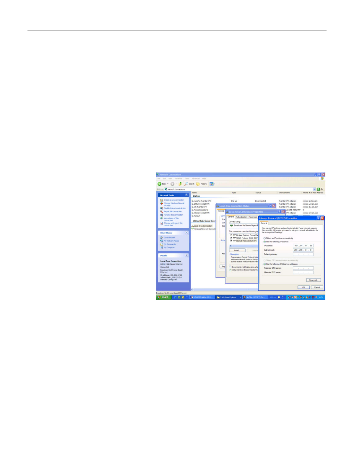
Application Exa
Outputting the IP Stress Test (Unicast)
mples
1. Perform steps
(See page 64.)
2. Instep5ofSet Up,settheTransmission
Mode to Unicast.
3. Select Control Panel >
Network Con
Connection > Properties > Internet
Protocol.
The Intern
dialog box appears.
4. In the dial
following IP address.
5. Enter an I
segment as the generator Source IP
address noted in step 5 of Set Up.
(See pag
increment the IP address by 1.
1 through 4 of Set Up.
nection > Local Area
et Protocol (TCP/IP) Properties
og box, select Use the
P address that is on the same
e 64.) The easiest way is to
6. Perform steps 6 through 10 of Set Up.
(See page 64.) This will set up the
test and perform the steps listed in
Outputting the IP Stress Test (Multicast)
to demonstrate the test.
72 MTS400P Quick Start User Manual

Accessories
Standard Accessories
The following table lists the standard accessories that are shipped with the MTS400P system:
Quantity Description Part number
1 each
1 each
1 each
1 each
1 each
1 each
1 each
1 each
1 each
1 each
1 each Front cover 200-4716-XX
1 each Power cord
Software package: MTS400 Series Application Software Media
TekRestore Software License
Certificate Of Authenticity: Microsoft Windows XP
Software package: MTS400 Series Product Documentation CD-ROM
MTS400P Quick Start User Manual
Supplemental information sheet; China ROHS
Software key, parallel port dongle
USB mouse
USB keyboard
Interface cable (D-sub 25–pin, twisted pair)
Option L0 (English)
Option L5 (Japanese)
Option A0 (North American Power)
Option A1 (Universal Euro Power)
Option A2 (United Kingdom Power)
Option A3 (Australia Power)
Option A4 (240V North America Power)
Option A5 (Switzerland Power)
Option A6 (Japan Power)
Option A10 (China Power)
Option A11 (India Power)
Option A99 (No Power cord or AC adapter)
Accessories
020-2994-XX
063-3906-XX
NA
063-4197-XX
071-2610-XX
071-2611-XX
071-2185-XX
119-6962-XX
119-6936-XX
119-B146-XX
012-A220-XX
MTS400P Quick Start User Manual 73

Accessories
Optional Accessories
MTS400P Optional Accessories
The following items are optional accessories:
Quantity Description Part number
Option IPTVP
1 each
Option SX
1 each
Option LX
1 each
Option ZX
1 each
Cable assembly; RF, BNC to BNC; 75 Ω 174-5135-XX
850 nm opti
1310 nm optical port 131-7957-XX
1550 nm optical port 131-7958-XX
cal port
131-7834-
XX
74 MTS400P Quick Start User Manual

User Maintenance
This appendix describes general care and service procedures for the MPEG Test System.
Preventive Maintenance provides cleaning instructions
In Case of Problems provides some hints for troubleshooting startup errors
Repackaging for Shipment gives instructions for packing and shipping the instrument
General Care
Protect the instrument from adverse weather conditions. The instrument is not waterproof.
User Maintenanc
e
CAUTION. T
Do not use chemical cleaning agents; they may damage the instrument. Avoid chemicals that contain benzene, toluene,
xylene, acetone,
o avoid damage to the instrument, do not expose it to sprays, liquids, or solvents.
or similar solvents.
Preventative Maintenance
Check the electrical performance and verify that the instrument accuracy is certified (calibrated) once a year.
Preventive maintenance mainly consists of periodic cleaning. Periodic cleaning reduces instrument breakdown and increases
reliability. You should clean the instrument as needed, based on the operating environment. Dirty conditions may require
more frequent cleaning than computer room conditions.
Cleaning the Exterior
Clean the ext
swab dampened with a 75% isopropyl alcohol solution. A swab is useful for cleaning in narrow spaces around the controls
and connectors. Do not use abrasive compounds on any part of the instrument.
CAUTION. Av
the cloth or swab. Use a 75% isopropyl alcohol solution as a cleanser and rinse with deionized w ater.
erior surfaces of the instrument with a dry, lint-free cloth or a soft-bristle brush. If dirt remains, use a cloth or
oid getting moisture inside the instrument during external cleaning and use only enough solution to dampen
Do not wash the front-panel On/Standby switch. Cover the switch while cleaning the instrument.
MTS400P Quick Start User Manual 75

User Maintenanc
e
Cleaning the Keyboard
Clean the exterior surfaces of the keyboard and integrated tracking device with a dry, lint-free cloth or a soft-bristle brush.
A swab is useful for cleaning in narrow spaces around the controls and connectors. Do not use abrasive compounds on
any part of the instrument.
CAUTION. Avoid getting moisture inside the keyboard and integrated tracking device during external cleaning and use
only enough solution to dampen the cloth or swab. Use a 75% isopropyl alcohol solution as a cleanser and rinse with
deionized water.
In Case of Problems
This section addresses problems that you may encounter while using the test system. This section does not identify
specific problems related to performance verification or adjustments. The diagnostic procedures for the MTS400P system
provided i
Specifications and Performance Verification Technical Reference, supplied as a PDF file on the MTS400 Series Product
Documentation CD-ROM.
Power-on diagnostics run when you first power on the instrument to start the test system application. These diagnostics
check the
there may be a system error that prevents the MTS400P system software from starting.
n this section can help you isolate problems. For a performance verification procedure, refer to the MTS400P
operating system and hardware for correct operation. If error messages occur during the power-on diagnostics,
owing table lists some of the symptoms of hardware problems (related to the operating system and peripheral devices)
The foll
and possible solutions.
Symptom
Instrument does not power on
Instrument powers on but does not complete
the power-on sequence
er-on diagnostics fail
Pow
Instrument does not recognize accessories
h as monitor, printer, or keyboard
suc
Instrument will not power off with the
On/Standby switch
Possible causes and recommended actions
that the power cord is connected to the instrument and to the power
Verify
source.
Check that the instrument receives power when you push the On/Standby
h; check that the fans start.
switc
Check that power is available at the power source.
Contact your local Tektronix service center.
Check for and remove any disk in the floppy disk drive; make sure the
rument boots from the hard d isk drive.
inst
tact your local Tektronix service center.
Con
ck that accessories are properly connected or installed.
Che
Contact your local Tektronix service center.
Try powering off the instrument using the Windows XP shutdown
procedure. If the instrument still does not power off, use the task manager
o close down tasks. Finally, try the hard shutdown procedure; push and
t
hold the On/Standby switch for five seconds to power off the instrument.
76 MTS400P Quick Start User Manual

User Maintenanc
Software Problems
Your MPEG Test System comes with software already installed. For any suspected software problems, try to isolate the
problem to the test s ystem application software or to other installed software.
If you suspect networking problems, see Network Troubleshooting. (See page 13, Network Troubleshooting.)
Hardware Problems
e
Hardware pr
properly installed the instrument. There are no user serviceable parts in the MTS400 Series systems, so you should contact
your local Tektronix Service representative if your instrument has a hardware problem.
Repackagi
Your instrument was originally shipped by Tektronix in a carton with packaging components designed to protect the
instrument from damage during shipment. If you need to ship the instrument to another location, it is strongly recommended
that you use the original shipping carton and packaging components to provide adequate protection during shipment.
CAUTION. To prevent the invalidation of your instrument’s warranties, Tektronix strongly recommends that you use your
original shipping carton (one that is in good condition) when you ship the instrument to another location or when you
return the instrument to a Tektronix service center for repair.
Tektronix cannot honor the instrument’s warranties if the instrument arrives at the service center damaged and it was not
shipped in its original carton or in a replacement carton (and its supporting packaging material) purchased from Tektronix. If
you lose your original packaging material, contact your Tektronix representative to obtain replacement packaging.
Packaging Inspection
When preparing to ship your instrument to another location, it is important to inspect your packaging materials for condition
and mi
oblems can have several causes. Review the installation instructions in this manual to verify that you have
ng for Shipment
ssing components.
condition of your packaging materials is poor, or if you are missing some of the components, it is strongly recommended
If the
that you order a new packaging kit.
Replacement Packaging Materials
New packaging materials are available from Tektronix. To obtain these items, contact your Tektronix representative. The
replacement packaging kit includes all the material required to properly package the instrument for shipment.
MTS400P Quick Start User Manual 77

User Maintenanc
Repackaging Procedure
When the instrument is shipped, it is important to package it well to protect the instrument. It is not necessary to return the
accessories received with the instrument when returning the instrument for repair.
NOTE. If you return the test system to a Tektronix Service Center for upgrade or repair, do not remove the software key.
1. If the instrument is to be shipped to a Tektronix field office for repair, attach a tag to the instrument showing the following:
2. Place the protective front cover on the front of the instrument.
3. Place the instrument in the protective bag. The bag prevents dust, moisture, and other debris from entering the cabinet.
4. Fold the top of the bag neatly over the top of the instrument to make it as flat as possible and seal with packing tape.
5. Place the front cushion over the front of the instrument.
6. Place the rear cushion over the rear of the instrument.
e
Owner’s name and address
Instrument serial number
Description of the problem(s) enc ountered and/or service required.
7. Carefully lift the instrument with front and rear cushions attached and lower it into the shipping box.
8. Position the cardboard tray into the top of the box, pressing the tray down until it rests on the tops of the front and
rear cushions.
NOTE. To ensure packaging integrity and product safety, the tray must be installed regardless of whether accessories
are being included in the package.
9. If you are shipping the accessories, arrange the accessories in the tray.
10. Close and tape the shipping box.
11. Attach the appropriate shipping documents needed to ship the instrument to its destination.
78 MTS400P Quick Start User Manual

Index
Index
A
AC line voltag
Accessories
BNC cable, 3
SFP module, 3
Add Elementary Streams, 50
Analyzers, 21
Applicatio
Arrow buttons, 20
ASI/SMPTE Input connector, 7
ASI/SMPTE
e requirement, 2
nExamples, 44
Output connector, 7
B
Basic Requirements, 13
Benefits, viii
C
Close button, 19
Cancel/
Cleaning
exterior, 75
d, 76
keyboar
Cleaning the instrument, 75
Clock/Ref In connector, 6
Com con
Connecting to a PC, 8
Conventions, ix
Create
Crossover Ethernet cable, 8
nector, 7
a New Stream, 44
D
DHCP (Dynamic Host Configuration
ocol), 42
Prot
Documentation, viii
Duplex operation, 26
E
ctrical power requirements, 2
Ele
Elementary Stream Acquisition, 49
Elementary Stream Analyzer, 37
er button, 19
Ent
Entering Numeric Data, 25
Environment operating
quirements, 1
re
ES Analyzer, 37
Ethernet connector, 7
Ethernet parameters
setting, 40
Examine Stre
am Content, 62
F
Features, viii
Finding IP Addresses, 18
Front Panel
Functional Check Procedure, 18
Connectors, 19
G
GbE interface
BNC cable
SFP module, 3
General care, 7 5
Generato
,3
rs, 22
H
Hardware problems, 77
HDD access indicator, 20
I
IEEE 13
Incorrect Default Gateway, 15
Incorrect IP Address, 13
Incor
Initial product inspection, 1
Installation, 1
IP Parameters, 13
94b connector, 8
rect Subnet Mask, 14
rk, 13
netwo
L
LAN connector, 7
ense, 10
Lic
Loopback, 26
M
Maintenance, 75
nu button, 20
Me
MPEG Player Setup, 26
MTS400 applications, 28
N
Network Infor
Network installation, 13
Network Troubleshooting, 13
Num Pad/Sele
Numeric data entry, 25
mation, 18
ct button, 20
O
On/Standby switch, 19
ON/STBY po
Operating Considerations, 1
Operation, 21
Optional A
wer switch, 19
ccessories
MTS400 Series, 74
P
Packaging, 77
ng Inspection, 77
Packagi
PES, 29
PES Analyzer, 29
a Host Machine, 16
Pinging
Play/Pause button, 20
Players, 22
t/Analysis, 27
Playou
Power connector, 8
Power cord requirements, 2
ng Off the Instrument, 10
Poweri
Powering On the Instrument, 9
Preface, viii
ntative maintenance, 75
Preve
Printer connector, 7
Procedures
ng up FlexVu, 57
setti
Product
inspection, 1
uct Description, 21
Prod
R
Rear Panel Connectors, 6
Record
ton, 20
but
Related documentation, viii
Related documents, viii
packaging for shipment, 77
Re
Repackaging Procedure, 78
Replacement, 77
MTS400P Quick Start User Manual 79

Index
S
Safety Summary, iii
Setting Ether
Setting Up Loopback, 26
Setting up the FlexVu display, 57
SFP (small for
SFP module, 3
Shipping the instrument, 77
SMPTE310M/A
SMPTE310M/ASI output, 7
Software
Software Applications, 21
Software problems, 77
SPI In/Out
SPI input, 7
net parameters, 40
mat pluggable) port, 7
SI input, 7
license, 10
connector, 6
Standard accessories
MTS400 Series,
Start menu, 23
Stop button, 19
T
T-STD Buffer
Tab button, 20
Tracing the Route, 17
Trig In/Out
Troubleshooting
power-on failures, 76
Troublesho
TSCA, 28
TSCA Setup, 26
Analyzer, 32
connector, 7
oting Procedures, 15
73
U
USB connectors, 20
Using
Arrow buttons
keypad, 25
Utilities, 22
V
VGA connecto
VLC Media Player
Installation, 12
r, 7
,25
80 MTS400P Quick Start User Manual
 Loading...