


xx
MTS4000
MPEG Test Systems
ZZZ
Specifications and Performance Verification
Technical Reference
*P077062600*
077-0626-00


xx
MTS4000
MPEG Test Systems
ZZZ
Specifications and Performance Verification
Technical Reference
www.tektronix.com
077-0626-00

Copyright © Tektronix. All rights reserved. Licensed software products are owned by Tektronix or its subsidiaries
or suppliers, and are protected by national copyright laws and international treaty provisions.
Tektronix products are covered by U.S. and foreign patents, issued and pending. Information in this publication
supersedes that in all previously published material. Specifications and price change privileges reserved.
TEKTRONIX and TEK are registered trademarks of Tektronix, Inc.
Contacting Tektronix
Tektronix, Inc.
14150 SW Karl Braun D rive
P.O. B o x 5 0 0
Beaverto
USA
For product information, sales, service, and technical suppor t:
n, OR 97077
In North America, call 1-800-833-9200.
Worl dwid e, v isit www.tektronix.com to find contacts in your area.

Table of Contents
General Safety Summary ......................................................................................... iv
Preface ............................................................................................................. vii
Specifications .. ................................ .................................. ................................ ... 1
Performanc
Verification Procedures ........................................................................................... 13
eVerification ............... ................................ .................................. ......... 9
MTS4000 Specifications and Performance Verification i

Table of Contents
List of Figure
s
ii MTS4000 Specifications and Performance Verification

List of Tables
Table i: MTS4000 product documentation ................................... ................................. vii
Table 1 : Pla
Table 2: ASI card electrical characteristics....................... ................................ ............... 2
Table 3: DVB-S2 card characteristics............................. ................................ ............... 2
Table 4: DVB-S2 measurements........................... .................................. ..................... 3
Table 5: 8VSB card characteristics............................................................................... 3
Table 6: 8VSB measurements.................. ................................ .................................. . 4
Table 7 : Q
Table 8: QAM Annex B measurements.......................................................................... 5
Table 9: Video over IP card ............ .................................. ................................ ......... 6
Table 10: 10G Ethernet card . .................................. ................................ ................... 7
Table 11: AC power source electrical characteristics........................................................... 7
Table 12: Mechanical characteristics............................................................................. 8
Table
tform specifications .................................................................................. 1
AM Annex B card characteristics ............. .................................. ..................... 4
13: Environmental characteristics ......................................................................... 8
Table of Contents
MTS4000 Specifications and Performance Verification iii

General Safety Summary
General Safet
To Avoid Fire or Personal
Injury
ySummary
Review the fo
this product or any products connected to it.
To avoid pot
Only qualified personnel should perform service procedures.
While using this product, you may need to access other parts of a larger system.
Read the safety sections of the other component manuals for warnings and
cautions r
Use proper power cord. Use only the power cord specified for this product and
certified for the country of use.
Ground the product. This product is grounded through the g rounding conductor
of the power cord. To avoid electric shock, the grounding conductor must be
connected to earth ground. Before making connections to the input or output
terminals of the product, ensure that the product is properly grounded.
Observe all terminal ratings. To a void fire or shock hazard, observe all ratings
and markings on the product. Consult the product manual for further ratings
information before making connections to the product.
llowing safety precautions to avoid injury and prevent damage to
ential hazards, use this product only as specified.
elated to operating the system.
The inputs are not rated for connection to mains or Category II, III, or IV circuits.
Do not apply a potential to any terminal, including the common terminal, that
exceeds the maximum rating of that terminal.
Power disconnect. The power cord disconnects the product from the power source.
Donotblockthepowercord;itmustremain accessible to the user at all times.
Do not operate without covers. Do not operate this product with covers or panels
removed.
Do not operate with suspected failures. If you suspect that there is damage to this
product, have it inspected by qualified service personnel.
Avoid exposed circuitry. Do not touch exposed connections and components when
power is present.
Use proper fuse. Use only the fuse type and rating specified for this product.
Wear eye protection. Wear eye protection if exposure to high-intensity rays or
laser radiation exists.
iv MTS4000 Specifications and Performance Verification

General Safety Summary
TermsinThisManual
Symbols and Terms on the
Product
Do not operate i
Do not operate in an explosive atmosphere.
Keep product surfaces clean and dry.
Provide prop
on installing the product so it has proper ventilation.
These terms may appear in this manual:
WAR NI NG .
in injury or loss of life.
CAUTION
damage to this product or other property.
These t
erms may appear on the product:
DANGER indicates an injury hazard immediately accessible a s you read
the ma
n wet/damp conditions.
er ventilation. Refer to the manual's installation instructions for details
Warning statements identify conditions or practices that could result
. Caution statements identify conditions or practices that could result in
rking.
WARNING indicates an injury hazard not immediately accessible as you
the marking.
read
CAUTION indicates a hazard to property including the product.
The following symbol(s) may appear on the product:
MTS4000 Specifications and Performance Verification v

General Safety Summary
vi MTS4000 Specifications and Performance Verification

Preface
Preface
Related Manuals
This manual l
ists the electrical, mechanical, and environmental specifications, and
the certification and compliance statements for the Tektronix MTS4000 MPEG
Test System. Also provided are procedures for verifying the performance of the
test system.
NOTE. Text in this manual about the MPEG Player refers to the MPEG player
application installed in the MTS4000 system.
The following manuals are also available to use with the MTS4000 MPEG Test
System. These manuals are available on the MTS4000 Product Documentation
CD-ROM (
Tektronix part number 063-4386-xx) that was supplied with the test
system. Product documentation is also available from the Manuals Finder on
the Tektronix Web site.
Table i: MTS4000 product documentation
Item (Tektronix part number) Description
MTS4000 Quick Start User Manual
(071-2970-xx)
MTS4000Analyzer Applications User Manual
(077-0622-xx)
MTS4000 Generator Applications User
Manual (077-0623-xx)
MTS4000 Carousel Applications User
Manual (077-0624-xx)
MTS4000 Specifications and Performance
Verification Technical Reference
(077-0626-xx) (this manual)
MTS4000 Release Notes (077-0627-xx) Provides information about software
Provides installation and high-level
operational overviews
Provides in-depth operating information for
the MTS4000 analyzer applications
Provides in-depth operating information for
the MTS4000 generator applications
Provides in-depth operating information for
the MTS4090 carousel applications
Provides complete product specifications
and a procedure for v erifying the operation
of the instrument
problems and behaviors
MTS4000 Specifications and Performance Verification vii

Preface
viii MTS4000 Specifications and Performance Verification

Specifications
Table 1: Platform specifications
This chapter contains specifications for the MTS4000 MPEG Test Systems.
All specifications are guaranteed unless labeled “typical.” Typical specifications
are provided for your convenience but are not guaranteed.
To meet specifications, the following conditions must be met:
The system must be kept within the environmental limits specified in this
document.
The system must be powered from a source maintaining voltage and frequency
within the limits described in this document.
The system must have been operating c ontinuously for at least 20 minutes
within the specified operating temperature range.
Any conditions that are unique to a particular characteristic are expressly stated
as part of that characteristic.
cteristic
Chara
ting sys tem
Opera
Processor
Disk space
Operating system and
tware applications
sof
File storage
RAM
D-ROM drive
C
Display
Ethernet
10/100/1000 (GigE) Two 10/100/1000Base-T; RJ45 connector
Keyboard/mouse Integrated keyboard/mouse
External audio ports
External VGA Output
USB ports Six USB 2.0 device c onnectors, two on front, four on side
iption
Descr
soft Windows 7 Ultimate, 64 bit
Micro
l i7 860 Q uad core
Inte
500 GB SATA hard drive
GB SATA hard d rive
500
B
4G
D-R/W, DVD-R/RW, DVD+R/RW
C
CD, 1280 X 1024, 17 inch
L
Supported protocol: Ethernet/IP/UDP/ MPEG-TS and VLAN
When used in MPEG-TS analysis and record, the minimum and maximum link bit rates are
typically 250 kbps and 100 Mbps respectively
IP playout bit rate is typically up to 190 Mbps
External audio jacks for microphone input and line output
MTS4000 Specifications and Performance Verification 1

Specifications
Table 2: ASI car
d electrical characteristics
Characteristic Description
ASI card Quad ASI adapter for PCI Express bus, x4 Gen 1.
Connector type BNC 75 Ω (4x). Each port can be independently configured as input or output.
Tx or Rx Bit R
Physical layer
ate, typical
Up to 214 Mbp
DVB-ASI (co
smax
ax) EN50083-9
Return Loss, typical > 15 dB, typical
ASI Output (Demodulated RF Output)
Signal amplitude 1.0 V
max, 600 mV
p-p
min,intoa75Ω load.
p-p
Return loss 10 dB min at 270 MHz
Table 3: DVB-S2 card characteristics
Characteristic Description
Input frequency range
Input signal amplitude range, typical
Modulation format QPSK in accordance with DVB-S (ETSI EN 300 421)
Modulation baud rate 1 MBaud min, 60 MB aud max
Code rate DVB-S: 1/2, 2/3, 3/4, 5/6, 6/7, 7/8
FEC modes Viterbi and Reed-solomon in accordance with DVB-S
Roll off
Connector type
Input termination impedance
Input return loss, typical >6 dB, 950 MHz to 2150 MHz
LNB supply voltage
LNB supply maximum current 200 mA
LNB 22 kHz signalling frequency 22 kHz ±20%
LNB 22 kHz signalling amplitude
LNB m ode
950 MHz to 2150 MHz with 1 MHz step size
–60 dBm to –30 dBm for a CBE R of <1
e-6
Use high quality s hielded cables and higher input level to prevent ingress of interfering
signals. This is particularly important at the tuned frequency where the input circuitry is
by design most sensitive.
QPSK, 8PSK, 16APSK and 32APSK in accordance with DVB-S2 (ETSI EN 302 307)
including Constant, Adaptive and Variable Coding and Modulation (CCM, ACM and VCM)
Maximum symbol rate: 60 MBaud in QPSK, 45 MBaud in 8PSK, 39 MBaud in 16APSK ,
and 32 MBaud in 32APSK.
DVB-S2: 1/4, 1/3, 2/5, 1/2, 3/5, 2/3, 3/4, 4/5, 5/6, 8/9, 9/10
LDPC and BCH in accordance with DVB-S2
Short and Normal FEC blocks in accordance with DVB-S2
0.2, 0.25, 0.35
Ftype
75 Ω nominal
selectable; 13.0 V ±1.5 V or 18.0 V ±1.5 V, with 100 Ω, 5 watt resistor load
800 mV
with 100 Ω load
p-p
DiSEqC 2
2 MTS4000 Specifications and Performance Verification

Specifications
Table 4: DVB-S2
Measurement Description
RF lock
Input level (
EVM (Error Vector Magnitude), typical Display Range: ≤4.0% to ≥30.0% RMS
MER (Modul
equalizer, typical
C/N (Carrier to Noise ratio), typical
Phase noise, typical
Pre-Viterbi BER Pre-Viterbi BER is displayed
Pre-Reed Solomon (RS) BER Pre-RS BER is displayed
Pre-LDPC BER Pre-LDPC BER is displayed
Pre-BCH BER Pre-BCH BER is displayed
Post RS BER and TEF (Transport Error
Flag
Transmission parameter All coding and modul ation parameters are indicated to the user
Constellation
signal strength), typical
)
measurements
ation Error Ratio) with
RF lock is indi
Range: –60 dBm to –30 dBm
Resolution:
Accuracy: ±5 dB
Resolution: 0.1%
Accuracy: ±
Display Range: 10 dB to 30 dB with equalizer
Resolutio
Accuracy: ±2 dB for range from 10 to 28 dB
Display R
Resolution: 1 dB
Accuracy: ±2 dB for range from 10 to 28 dB
Display Range: 5 to 45 Degrees RMS
Resolut
Post Reed Solomon BER (TEF ratio), TEF rate, and number of Transport Error Flags
count) is displayed
(TEF
The RF constellation is displayed
cated by LED and Status
1dB
20% or reading
n: 1 dB
ange: 10 dB to 30 dB
ion: 1 Degree
Table 5: 8VSB card characteristics
Characteristic Description
Input frequency range 54 MHz to 860 MHz, VHF/UHF channels 2 to 69 (to include low VHF frequencies)
Input signal level
Modulation format 8VSB in accordance with ATSC A/53B
Receiver bandwidth 6 MHz
Input termination impedance
Connector type
Input return loss, typical 5 dB minimum
–72 dBm to –6 dBm (–23 dBmV to +43 dBmV)
Use high quality shielded cables and higher input level to prevent ingress of interfering
signals. This is particularly important at the tuned frequency where the input circuitry is
by design most sensitive.
75 Ω nominal
F-type
MTS4000 Specifications and Performance Verification 3

Specifications
Table 6: 8VSB me
Measurements Description
RF Lock
Input level (
EVM (Error Vector Magnitude), typical Display Range: ≤3.0% to ≥12.5% rms
Equivalent MER (Modulation Error
Ratio) with Equalizer, typical
SNR (Signal to Noise Ratio), typical
BER
TEF (Transport Error Flag) Transport Error Flags (uncorrectable error count) in a 1 second window and 10 second
Const
Echo profile, typical Equalizer filter tap information is displayed.
signal strength), typical
ellation diagram
asurements
RF lock is indi
Display Rang
Resolution: 1 dB
Accuracy: ±3 dB
Resolution
Accuracy: ±20% of reading
Display Ra
Resolution: 0.1 dB
Accuracy: ±1 dB for MER >25 dB; ±3 dB for MER 25 dB to 31 dB
(Measure
between –50 dBm and –15 dBm.)
Display R
Resolution: 1 dB
Accuracy: ±1dBforSNR<25dB;±3dBforSNR25dBto35dB
Pre-RS BER, SER 1 second and 10 seconds windows values are displayed
window
The 8V
constellation is not available). This is displayed as Symbol Distribution in the user interface
Display Echo Level range: Normalized real tap values over the range of –1 to 1
lay Delay range: –6.7 μs to 45.5 μs
Disp
cated by LED and Status
e: –72 dBm to –2 dBm relative to 75 Ω (–23 dBmV to +47 dBmV)
:0.1%
nge: 17 dB to 31 dB with Equalizer
d at –30 dBm input. For best MER accuracy, maintain the input signal level
ange: 15 dB to 35 dB
are displayed
SB constellation diagram is a display of I-data history with histograms (the IQ
Table 7: QAM Annex B card characteristics
Characteristic Description
Input frequency range
Input signal level, typical
Modulation format 64QAM, 256QAM (compliant with ITU J-83 Annex B)
Interleaving mode Level 1 and Level 2 interleaving support compliant with all ITU J-83 Annex B, excluding I,
Modulation baud rate
Spectrum polarity Demodulates both Normal and Inverted IF Spectrum
Receiver bandwidth, QAM B
Connector type
88 MHz to 858 MHz
–64 dBm to –19 dBm (45 dBuV to 90 dBuV relative to 75 Ω)
With either a 64 or 256 QAM input, there are five or fewer Transport Error Flags in
11 seconds, which corresponds to a post FEC rate of 1e
≥ –30 dBm when operated in an electromagnetic field of 3 V/m or more
J = (128,7) and (128,8), and in 256 QAM excluding (8, 16) and (16, 8)
64 QAM: 5.056941 Mbaud/s
256 QAM: 5.360537 Mbaud/s
6 MHz nominal
Ftype
–8
4 MTS4000 Specifications and Performance Verification

Table 7: QAM Annex B card characteristics (cont.)
Characteristic Description
Input termination impedance
Input return loss, typical 5 dB minimum
Ultimate Modulation Error Ratio with
equalizer, typical
75 Ω nominal
≥37 dB with an equalizer
Specifications
Table 8: Q
Measurem
RF lock
Input le
EVM (Error Vector Magnitude), typical
R (Modulation Error Ratio) with
ME
Equalizer, typical
SNR (Signal to Noise Ratio), typical
BER (Bit Error Ratio) Pre-RS BER is displayed
TEF (Transport Error Flag) Transport Error Flags (uncorrectable error count) in a 1 second window and 10 second
Constellation
AM Annex B measurements
ent
vel (signal strength), typical
Range
Resolution 1 dB
Accuracy ±3 dB
ay Range
Displ
M
64 QA
AM
256 Q
Resolution
Accuracy
isplay Range
D
4QAM
6
256 QAM
Resolution 0.1 dB
Accuracy
Display Range
64 QAM
256 QAM
Resolution Resolution: 1 dB
Accuracy
Descript
RF lock is
–64 dBm
≤1% t
≤1% t
0.1
±1
22 dB to 37 dB
28 dB to 37 dB
±1 dB for MER < 25 dB; ±3 db for MER 25 dB to 34 dB (measured at –30 dBm input)
22 dB to 37 dB
28 dB to 37 dB
Accuracy: ±1 dB for SNR < 25 dB; ±3 db for SNR 25 dB to 34 dB
window are displayed
The RF constellation is displayed
ion
indicated by LED and Status
to –19 dBm (45 dBuV to 90 dBuV relative to 75 Ω)
o ≥5% rms
o ≥2.5% rms
%
%
MTS4000 Specifications and Performance Verification 5

Specifications
Table 9: Video o
ver IP card
Characteristic Description
General Description
Ethernet por
ts
The interface supports full duplex operation only. Half duplex is not supported.
ASI input One ASI input for loop-through of ASI input
ASI output One AS I output for video over IP to ASI output or for ASI/SMPTE310M loop-through
of input signal selectable via SW control.
Transport stream rate over IP 250 K bps to 155 Mbps max
ASI Output (TS from Video over IP)
Connector BNC
Impedanc
Transpor
Signal a
e
t stream rate, typical
mplitude
75 Ω nominal, transformer coupled.
250 Kbps m
600 mV
in and up to 155 Mbps max.
min, 1.0 V
p-p
maxintoa75Ω load.
p-p
Return loss 10 dB min at 270 MHz
Ethernet Optical Port - General Characteristics
Optical operating mode Single mode or Multimode
Connector type Duplex data link MSA compliant SFP connector
Standard 1000 BASE-X
Data format
NRZ
Ethernet Optical Transmitter - Single mode 1550 nm using Tektronix supplied SFP module
Output power, typical
Center wavelength - 1550 nm, typical
Total jitter (peak-to-peak)
–2 dBm to +4 dBm
1530 nm Min, 1550 nm typical, 1570 nm max
<170 ps
Extinction ratio ≥9.0 dBm
Ethernet Optical Receiver - Single mode 1550 nm using Tektronix supplied SFP module
6 dBm to –3 dBm, BER ≤ 1X10
Optical input power, typical
put wavelength
In
Jitter tolerance
hernet Optical Transmitter - Single mode 1310 nm using Tektronix supplied SFP module
Et
utput power, typical
O
Center wavelength - 1310 nm, typical
–2
70 nm ≤λ≤1610 nm
12
EEE 802.3z and ANSI X3T11
I
–11 dBm to –3 dBm
1270 nm min, 1310 nm typical, 1355 nm max
–12
6 MTS4000 Specifications and Performance Verification

Specifications
Table 9: Video over IP card (cont.)
Ethernet Optical Transmitter - S ingle mode 1310 nm using Tektronix supplied SFP module
Total jitter (peak-to-peak)
Extinction ratio ≥9.0 dBm
Ethernet Optical Receiver - Single mode 1310 nm using Tektronix supplied SFP module
Optical input power, typical
Input wavelength 1270 nm ≤λ≤1610 nm
Jitter tolerance
Ethernet Optical Transmitter - Multim ode 850 nm using Tektronix supplied SFP module
Output power, typical
Center wavelength - 850 nm, typical
Total jitter (peak-to-peak)
Extinction ratio ≥9.0 dBm
Ethernet Optical Receiver - Multimode 850 nm using Tektronix supplied SFP module
Optical input power, typical
Input wavelength 770 nm ≤λ≤860 nm
Jitter tolerance
Ethernet Electrical Port
Standard 10/100/1000BASE-T IEEE 802.3
Connector type
Data format 10/100 Base T
Data format 1000 Base T Trellis encoded, PAM5 symbols full-duplex on 4-pair Cat-5 UTP per IEEE 802.3ab
<170 ps
–19 dBm to –3 dBm, BER ≤ 1X10
–12
IEEE 802.3z and ANSI X3T11
–9.5 dBm to –2 dBm
830 nm min, 850 nm typical, 860 nm max
<170 ps
–17 dBm to 0 dBm, BER ≤ 1X10
–12
IEEE 802.3z and ANSI X3T11
RJ-45
NRZ
Table 10: 10G Ethernet card
aracteristic
Ch
eneral Description
G
Ethernet ports
Transport stream rate over IP, typical 700 Mbps throughput
Ethernet Optical port
Optical operating mode Multi mode SR
Connector type SFP+
Standard
Physical layer interface 10GBASE-SR (E10G41BFSR, E10G42BFSR)
scription
De
ual 10 Gigabit SFP+ Ethernet connections supporting 10GBASE-SR
D
IEEE 802.3
Table 11: AC power source electrical characteristics
Characteristic Description
Source voltage 100 to 240 VAC. Fluctuations must not exceed 10% of the nominal rated voltage.
Frequency range
50/60 Hz
MTS4000 Specifications and Performance Verification 7

Specifications
Table 11: AC power source electrical characteristics (cont.)
Characteristic Description
Power consumption
Mains fuse
220 W maximum, 100 - 240 V, 50/60 Hz.
Not operator replaceable.
Table 12: Mechanical characteristics
Characteristic Description
Classification
Cooling air flow Intake is from the side of the instrument, and exhaust is to the rear of the instrument.
Overall dimensions Height: 346.0 mm (13.62 in)
Weight
ping weight
Ship
Bench top instrument.
For prop
er cooling, at least two inches (51 mm) of clearance is needed on the sides
and rear of the instrument cabinet
Width: 434.5 mm (17.01 in)
243.0 mm (9.57 in)
Depth:
g (37.48 lb)
17.0 k
kg (44.53 lb)
20.2
Table 13: Environmental characteristics
Characteristic Description
Atmospherics
Temperature
Operating +5 °C to +40 °C, 30 °C per hour maximum gradient; temperature of the intake air at the
front and sides of the instrument
Non-operating
Humidity
Operating 20% to 80% relative humidity, non-condensing.
Non-operating
Altitude
Operating 0 to 3000 m (9800 ft).
Non-operating
Dynamics
Random vibration
Operating 0.27 g
Non-operating
Sine vibration, operating 0.013 inch peak-to-peak displacement from 5 Hz to 55 Hz
Functional shock, non-operating
–20 °C to +60 °C, 30 °C per hour maximum gradient
Max wet bulb temperature: +29 °C (derates relative humidity to ~22% at 50 °C).
10% to 80% relative humidity, non-condensing.
0 to 12,000 m (40,000 ft).
total from 5 to 500 Hz.
rms
2.28 g
total from 5 to 500 Hz.
rms
30 g, 11 ms half-sine
8 MTS4000 Specifications and Performance Verification

Performance Verification
The procedures in this section allow you to verify the performance of the
following MTS4000 MPEG Test System components:
ASI Interface
10 G Interface
MTS4000 Platform and System Software
Preparation
Required Equipment
Before you begin the Performance Verification procedures, review the following
information:
Ensure that the procedures are performed only by qualified service personnel
who have read the General Safety Summary at the front of this manual.
Ensure that the service personnel are familiar with system operation (refer to
the MTS4000 MPEG Test System Quick Start User Manual).
You will need the following equipment to perform the verification procedures:
75 Ω BNC-to-BNC cable (quantity of one) Tektronix part number
174-4954-00.
RJ45 network cable.
850 nm fiber cable.
A copy of the “sym1.mpg” transport stream file.
NOTE. The “sym1.mpg” transport stream file is supplied with every instrument in
the following directory: C:\Test Streams.
You can also obtain this fi le from the MTS4000 Documentation Browser CD or
from the Tclips MPEG Test Stream Software DVD.
Prepare the Instrument
MTS4000 Specifications and Performance Verification 9
Perform the following steps to prepare the instrument to be tested:
1. Make sure the dongle is securely installed on a USB port.
2. Make the following cable connections on the instrument.
Connect the 75 Ω BNC-to-BNC cable b etween the ASI 3 and ASI 4 ports
on the ASI card.
Connect the RJ45 network c able between the two network connectors on
the instrument side panel.
Connect the 850 nm fiber cable between the ports on the 10G card (if
installed).

Performance Verification
Standard 1G network loopback connection ASI loopback connectio n and 10G optical loopback connection
3. Connect the power cord to the side-panel power input connector.
4. Power on the MTS4000 system.
10 MTS4000 Specifications and Performance Verification

Performance Verification
MPEG Player Initial Setup.
The verificatio
Prepare the MPEG Player using the following steps.
1. Start the MPEG
NOTE. If the Recommended Settings dialog box displays, dismiss the box by
selecting OK.
2. Open the sym1.mpg transport stream file.
a. Click File
b. Select the file and click Open.
3. In the Play menu, set the following:
NOTE. In the MPEG Player menus, a check mark appears next to the selected
setting
for some menu parameters.
a. Packet Size : 188.
b. Clock: Select Default in the dialog box to display the Default Clock
n procedures use the MPEG player to play out a test stream file.
Player by double-clicking the icon on the desktop.
> Open and locate the file sym1.mpg (C:\TestStreams).
dialog box. Select OK in the Default Clock dialog box.
c. Update: On.
MTS4000 Specifications and Performance Verification 11

Performance Verification
d. PCR Initial Val
box.
e. Source: Di
f. Loop: On.
g. Other: Set the Standard to DVB. The select Update.
Select the C ontinuity Counter check box.
Select the PCR/PTS/DTS check box.
ue: Set Base Value and Exten sion Value to 0 in the dialog
sk.
Select the TDS/TOT/STT check box.
the NPT check box.
Clear
Do not close the MPEG Player application.
12 MTS4000 Specifications and Performance Verification

Verification Procedures
Verification P
ASI Loopback Test
rocedures
Perform the f
properly. The steps are written with the assumption that you are performing all
of the steps in order. If you start the procedures in the middle, you will have to
review previous steps for instrument setup.
1. In the MPEG Player, set the following:
a. Select Pla
b. Select ASI > ASI Out > ASI-3.
ollowing steps to verify that the MTS4000 system is operating
y > Interface > ASI.
c. In t
2. St
MTS4000 Specifications and Performance Verification 13
he MPEG Player toolbar, click the green Play arrow to start playing
the transport stream file.
art the TS Compliance Analyser by double-clicking the icon on the desktop.

Verification Procedures
3. Set the Real-ti
4. Click OK to accept the changes and close the Select Real-time Interface
dialog box.
After a few seconds, the TSCA window opens with the analysis results of the
ASI transport stream. Some EIT errors are acceptable.
me Interface to ASI-4.
14 MTS4000 Specifications and Performance Verification

Verification Procedures
MTS4000 Specifications and Performance Verification 15

Verification Procedures
1G Ethernet Loopback Test
10G Loopback Test
The steps in thi
1G Ethernet ports and the optional 10G optical interface card ports.
The example screen shots display the names and connections for the 1G Ethernet
ports. The 10G optic
NOTE. Do not attempt to perform the two loopback test simultaneously. First test
the 1G Ethernet ports, then if installed, test the 10G optical ports.
1. Verify that the ports are active.
a. 1G Standard Ethernet ports: With a loopback cable connected, verify
that the LEDs on the Et
cable connections if the LEDs are off.
b. 10G Optical Interface ports: With a loopback cable connected, verify that
the LEDs on the optical por
connections if the LEDs are off.
NOTE. For ease of identifying the ports, if you need to verify both the 1G Standard
Ethernet ports and the 10G Optical ports, do not have both loopback cables
connected at the same time.
s procedure can be used to perform a loopback test on the standard
al ports have identical screens, but different adapter names.
hernet ports are on or blinking. Check the RJ45
ts are on or blinking. Check the fiber cable
2. Open the Network and Sh
You should see two local area connections displayed.
aring Center in the Windows Control Panel.
16 MTS4000 Specifications and Performance Verification

Verification Procedures
4. Configure the tw
192.168.1.200 on the MTS4000.
a. Select the firs
dialog screen. Configure it to 192.168.1.100 IP address. (This will be
used for the MPEG Player.)
o ports as static IP addresses 192.168.1.100 and
t Local Area Connection and then click Properties in the
MTS4000 Specifications and Performance Verification 17

Verification Procedures
b. Highlight Inte
rnet Protocol Version 4 (TCP/IPv4) and select Properties.
18 MTS4000 Specifications and Performance Verification

Verification Procedures
c. Select Use the f
ollowing IP address: and enter the value 192.168.1.100.
d. Select the second Local Area Connection and set the IP address to
192.168.1.200. Use the same method as described for setting the first
Local Area Connection. (This will be used for TSCA input.)
5. Start the MPEG player and open the Sym1.mpg file.
MTS4000 Specifications and Performance Verification 19
Verification Procedures
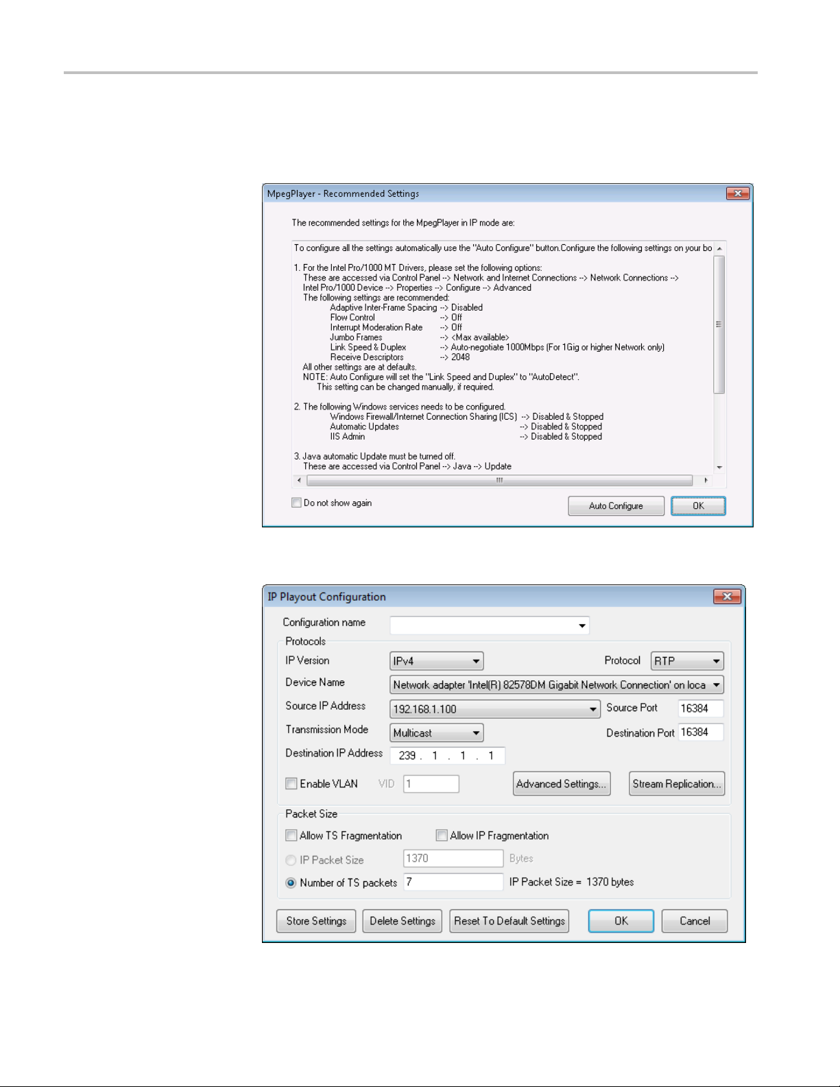
6. In the MPEG play
If the following pop-up displays, select OK. Do not use Auto Configure.
er toolbar, select Play > Interface > IP.
7. In the M PEG player toolbar, select IP > Configure.
20 MTS4000 Specifications and Performance Verification

Verification Procedures
8. Configure the IP
a. Use the Device Name pull-down list and select the adapter that you set the
IP address to 1
b. Click Stream Replication and enter 0 (no stream replication).
9. In the MPEG Player toolbar, click the green Play arrow to start playing the
transport strea m file.
10. Start the TS Compliance Analyzer a nd choose IP interface.
If this is the first time the IP interface has been selected, double click the red
area in preset or click the “+” button once
interface.
92.168.1.100. This is to be used for playout.
MTS4000 Specifications and Performance Verification 21

Verification Procedures
11. Browse to the st
Intel(R) 82583V Gigabit Network Connection.
12. Click on the “green” stream on the list for analysis where source IP is
192.168
13. Close all remaining configuration screens, and the analysis will start.
.1.100 (this is from MPEG Player) and select OK.
ream coming to 192.168.1.200 port. In this example, it is the
14. Some EIT errors are acceptable, see below:
22 MTS4000 Specifications and Performance Verification

Verification Procedures
Shut Down the Instrument
MTS4000 Specifications and Performance Verification 23
The Performance Verification procedure is complete.
Power off the ins trument and disconnect the signal cables .
 Loading...