


xx
MTS400 Series
ZZZ
Generator Applications
User Manual
*P077020401*
077-0204-01


xx
MTS400 Series
ZZZ
Generator Applications
User Manual
This document supports version 1.8 and above.
www.tektronix.com
077-0204-01

Copyright © Tektronix. All rights reserved. Licensed software products are owned by Tektronix or its subsidiaries
or suppliers, and are protected by national copyright laws and international treaty provisions.
Tektronix products are covered by U.S. and foreign patents, issued and pending. Information in this publication
supersedes that in all previously published material. Specifications and price change privileges reserved.
TEKTRONIX and TEK are registered trademarks of Tektronix, Inc.
Contacting Tektronix
Tektronix, Inc.
14200 SW Karl Braun Drive
P.O. B o x 500
Beaverto
USA
For product information, sales, service, and technical support:
n, OR 97077
In North America, call 1-800-833-9200.
Worl dwid e, vi s it www.tektronix.com to find contacts in your area.

Warranty
Tektronix warrants that this product will be free from defects in materials and workmanship for a period of o ne (1)
year from the date of shipment. If any such product proves defective during this warranty period, Tektronix, at its
option, either will repair the defective product without charge for parts and labor, or will provide a replacement
in exchange for the defective product. Parts, modules and replacement products used by Tektronix for warranty
work may be n
the property of Tektronix.
ew or reconditioned to like new performance. All replaced parts, modules and products become
In order to o
the warranty period and make suitable arrangements for the performance of service. Customer shall be responsible
for packaging and shipping the d efective product to the s ervice center designated by Tektronix, with shipping
charges prepaid. Tektronix shall pay for the return of the product to Customer if the shipment is to a location within
the country in which the Tektronix service center is located. Customer shall be responsible for paying all shipping
charges, duties, taxes, and any other charges for products returned to any other locations.
This warranty shall not apply to any defect, failure or damage caused by improper use or improper or inadequate
maintenance and care. Tektronix shall not be obligated to furnish service under this warranty a) to repair damage
result
b) to repair damage resulting from improper use or connection to incompatible equipment; c) to repair any damage
or malfunction caused by the use of non-Tektronix supplies; or d) to service a product that has been modified or
integrated with other products when the effect of such modification or integration increases the time or difficulty
of servicing the product.
THIS WARRANTY IS GIVEN BY TEKTRONIX WITH RESPECT TO THE PRODUCT IN LIEU OF ANY
OTHER WARRANTIES, EXPRESS OR IMPLIED. TEKTRONIX AND ITS VENDORS DISCLAIM ANY
IMPLIED WARRANTIES OF MERCHANTABILITY OR FITNESS FOR A PARTICULAR PURPOSE.
TRONIX’ RESPONSIBILITY TO REPAIR OR REPLACE DEFECTIVE PRODUCTS IS THE SOLE
TEK
AND EXCLUSIVE REMEDY PROVIDED TO THE CUSTOMER FOR BREACH OF THIS WARRANTY.
TEKTRONIX AND ITS VENDORS WILL NOT BE LIABLE FOR A NY INDIRECT, SPECIAL, INCIDENTAL,
OR CONSEQUENTIAL DAMAGES IRRESPECTIVE OF WHETHER TEKTRONIX OR THE VENDOR HAS
ADVANCE NOTICE OF THE POSSIBILITY OF SUCH DAMAGES.
[W2 – 15AUG04]
btain service under this warranty, Customer must notify Tektronix of the defect before the expiration of
ing from attempts by personnel other than Tektronix representatives to install, repair or service the product;


Table of Contents
General Safety Summary ........................................................................................ vii
Preface .............................................................................................................. ix
Documentation ................................................................................................ xi
Multiplexer
Multiplexer - Getting Started ..... . ..... . ..... . ..... . ... . . ..... . ..... . ..... . ..... . ..... . ... . . . .... . ..... . ..... . .. 1-1
H.264 ES Input Characteristics............................................................................. 1-4
Starting the Program......................................................................................... 1-5
Scripts ......................................................................................................... 1-6
Opening a Stream.......................................................................................... 1-12
Closing Files ............................................................................................... 1-17
Menus and Controls ............................................................................................ 1-18
Menu Options .............................................................................................. 1-18
Toolbar ........................... ................................ .................................. ......... 1-22
Status Bar................................................................................................... 1-22
User Interface .............................................................................................. 1-24
Wizards ......... .................................. ................................ ............................... 1-28
Transport Wizard ......................... ................................ ................................ . 1-28
Program Wizard....................... ................................ .................................. ... 1-33
Views............................................................................................................. 1-45
Navigator Views .................. .................................. ................................ ....... 1-45
Section View ............................................................................................... 1-49
Structure Diagram Manipulation......................................................................... 1-58
Event Log........................................ ................................ ........................... 1-59
Examine Transport Stream Window.................................. .................................. . 1-59
SI Filtering.. . ..... . ..... . ..... . ..... . ... . . . .... . . .... . ..... . ..... . ..... . ..... . ..... . ..... . ..... . ..... .... . . . 1-62
Component Views .............. ................................ ................................ ........... 1-66
Common Menu Options...................... .................................. ........................... 1-73
Editing in the Navigator Views . ..... . ..... . ..... . ... . . ..... . ..... . ..... . ... . . . .... . ..... . ..... . ..... . ..... . .. 1-74
Dragging and Dropping................................................................................... 1-74
Transport Stream........................................................................................... 1-74
Programs.................................................................................................... 1-75
Tables ...... .................................. ................................ ............................... 1-77
Sections .................... .................................. ................................ ............... 1-80
ES PIDs.......... ................................ ................................ ........................... 1-88
DSM-CC.................................................................................................... 1-97
Editing in Section View. . . ..... . ..... . ..... . ..... . ... . . . .... . ..... . ..... . ..... . ..... . ..... ..... . ..... . ..... . ... 1-99
Editing Fields. ..... . ..... ..... . ..... . ..... . .... . . .... . ..... . ..... . .... . ..... . ..... . .... . . .... . ..... . ..... . .. 1-99
MTS400 Series Generator Applications User Manual i

Table of Contents
Multiplexing T
Starting the Multiplex Engine . ... . . . .... . . .... . ..... . ..... . ..... . ..... . ..... . ..... ..... . ..... . ..... . .... 1-106
Errors and Reporting ..................... ................................ ................................ 1-107
Stopping the Multiplex Engine . . ... . . . ... . . . ..... . ..... . ..... . ..... . ..... . ..... . ..... . ..... . ..... . ..... . 1-108
Exporting the Multiplex Configuration File ........................................................... 1-108
Make Seamless................................................................................................. 1-110
Enabling the Seamless Option....................... ................................ .................... 1-110
Seamless Settings......................................................................................... 1-110
Reference ....... .................................. ................................ .............................. 1-112
Abbreviations ............................................................................................. 1-112
ransport Streams ............................................................................. 1-106
Transport Stream Editor
Transport Stream Editor ......................................................................................... 2-1
Starting the Program......................................................................................... 2-2
Options........................................................................................................ 2-3
Opening a File................................................................................................ 2-5
Menus and Controls .............................................................................................. 2-8
Toolbar..................... ................................ ................................ ................... 2-8
Status Bar..................................................................................................... 2-9
Slider Bar ..................................................................................................... 2-9
Menu Options .............................................................................................. 2-11
Hex Editor....................................................................................................... 2-14
Color Coding ............................................................................................... 2-14
Selecting & Editing... . .... . ..... . ..... . ..... . ..... . ... . . . .... . ..... . ..... . ..... . ..... . ..... ..... . ..... . ... 2-15
Header Editor ................................................................................................... 2-18
Header Information Tab...... ................................ ................................ ............. 2-18
Adaptation Field Tab ................................... ................................ ................... 2-20
Adaptation Field Extension Tab.......................................................................... 2-22
PID Remapping................ ................................ .................................. ............... 2-24
PCR Recalculation ............................................................................................. 2-27
Jitter Functions .. . ..... . ..... . ..... . ..... . ..... . . .... . . .... . . .... . . ... . . . ... . . . ... . . . ... . . . ... . . . ... . . . ... . . 2-34
MPEG Player
MPEG Player - Getting Started . . .... . ..... . ..... . ..... . ..... . ..... . ..... . ..... . ..... . ..... . ..... . ..... . ..... . .. 3-1
Display Elements ................. ................................ .................................. ......... 3-2
Hierarchical Display......................................................................................... 3-7
Menus and Controls ............................................................................................ 3-21
Menus in the Play Screen ................................................................................. 3-21
Menus in the Record Screen....... ................................ ................................ ....... 3-60
Toolbar Buttons ............................................................................................ 3-66
ii MTS400 Series Generator Applications User Manual

Reference ..... .................................. ................................ ................................ . 3-68
Interface Card (SPI/ASI/310M Option).. ................................ ............................... 3-68
Adding Jitter to PCRs .... . .... . ..... . ..... . ... . . . .... . ..... . ..... . ... . . ..... . ..... . ... . . . .... . ..... . ..... . 3-69
Using Preset Files................................... ................................ ....................... 3-71
Using the Continuous Recording Feature .............. ................................ ................. 3-72
Performing Continuous Recording ... ................................ ................................ ... 3-73
Remote Commands........................................................................................ 3-75
Make Seamless Wizard
Make Seamless Wizard .......................................................................................... 4-1
Starting the Wizard .......................................................................................... 4-1
Selecting an Input File ...................................................................................... 4-3
Select a Program to Make Seamless.............. ................................ ......................... 4-6
Selecting a Multiplex Output File. ..... . ..... . ..... . ..... . .... . . .... . ..... . ..... . ..... . ..... ..... . ..... . ... 4-9
Table of Contents
Transport Stream C
Transport Stream Cutter ......................................................................................... 5-1
Starting the Wizard .......................................................................................... 5-3
Cutting a File . ..... . ..... . ..... . ..... . ..... . ... . . ..... . ..... . ..... . ..... . ..... . ..... . ..... . ... . . . .... . . .... . .. 5-3
Script Pad
Script Pad - Getting Started . ... . . ..... . ..... . .... . ..... . ..... . .... . ..... . ..... . .... . ..... . ..... . .... . ..... . ... . . 6-1
Setting Up ... . ..... . ... . . ..... . ..... . ..... . ..... . .... . . .... . ..... . ..... . ..... . ..... . ..... . ... . . ..... . ..... . ... 6-1
Starting the Program......................................................................................... 6-1
Initial Appearanc
Initial Menu Options . ... . . . .... . ..... . ..... . ..... ..... . ..... . ..... . ..... . .... . . .... . ..... . ..... . ..... . .... . . 6-2
Script File Appearance ...................................................................................... 6-3
Opening a File................................................................................................ 6-3
Menu and Controls ............................................................................................... 6-6
Menu Bar ..................................................................................................... 6-6
Toolbar ........................... ................................ .................................. ........... 6-8
Status Bar..................................................................................................... 6-9
Script File Editing and Encryption . ..... . ..... . ..... . ... . . ..... . ..... . ..... . .... . . .... . ..... . ..... . ..... ..... 6-10
Keyword Color-Coding ................................................................................... 6-10
Parsing ..... ................................ ................................ ................................. 6-10
Encryption....... ................................ .................................. ......................... 6-11
utter
e ........................................................................................... 6-2
Index
Index
MTS400 Series Generator Applications User Manual iii

Table of Contents
List of Figure
Figure 1-1: Expert mode............ ................................ ................................ ........... 1-56
Figure 1-2:
Figure 3-1: Optional status bar.................................................................................. 3-6
Figure 3-2: IP status bar ......................................................................................... 3-6
Figure 3-3: Example of the hierarchical display ................. ................................ ............. 3-8
Figure 3-4: PCR Inaccuracy dialog box ..................................................................... 3-19
Figure 3-5: Clock dialog box for Option Interface .... .................................. ................... 3-24
Figure 3-
Figure 3-7: Default Clock Dialog box ....................................................................... 3-27
Figure 3-8: PCR Initial Value dialog box . . ..... . ..... . ... . . ..... . ..... . .... . . .... . ..... . ..... . ..... ..... . ... 3-29
Figure 3-9: Start/Stop Position dialog box ..... . ..... . ..... . ..... . ..... . ..... . ..... . ..... . ..... . ..... . ..... . 3-30
Figure 3-10: Timer Play/Record dialog box...................................... ........................... 3-32
Figure 3-11: Others dialog box ............................ .................................. ................. 3-33
Figur
Figure 3-13: ISDB/P-TS dialog box......................... .................................. ............... 3-35
Figure 3-14: Select Update Item dialog box................................................................. 3-36
Figure 3-15: IP Configuration for IPv4 ...................................................................... 3-38
Figure 3-16: IP Configuration for IPv6 ...................................................................... 3-39
Figure 3-17: Advanced Protocol Settings dialog box for IPv4 . ..... . .... . . .... . ..... . ..... . ..... ..... . ... 3-41
gure 3-18: Advanced Protocol Settings dialog box for IPv6 . ..... . .... . . .... . ..... . ..... . ..... ..... . ... 3-41
Fi
Figure 3-19: Stream Replication Settings for IPv4 ... . . . .... . . .... . . .... . ..... . ..... . ..... . ..... . ..... . .... 3-43
Figure 3-20: Stream Replication Settings for IPv6 ... . . . .... . . .... . . .... . ..... . ..... . ..... . ..... . ..... . .... 3-43
Figure 3-21: Error Insertion dialog box...................................................................... 3-47
Figure 3-22: Windows Firewall/Internet Connection Sharing (ICS) . ..... . ..... . ..... . ..... . ..... . ..... . 3-53
Figure 3-23: Automatic Updates Properties................................................................. 3-54
Figure 3-24: IIS Admin Properties ........................................................................... 3-55
Figure 3-25: Java Control Panel .............................................................................. 3-56
Figure 3-26: Java Update-Warning .................................. ................................ ......... 3-56
Figure 3-27: Registry Editor ....... .................................. ................................ ......... 3-57
Figure 3-28: Edit DWORD Value . ................................ ................................ ........... 3-58
Figure 3-29: Communication dialog box .................................................................... 3-59
Figure 3-30: PCR Inaccuracy dialog box ................... ................................ ................. 3-69
Standard mode .................................................................................... 1-57
6: Clock dialog box for IP interface.... ................................ ........................... 3-24
e 3-12: TDT/TOT dialog box .............. ................................ ............................. 3-34
s
iv MTS400 Series Generator Applications User Manual

List of Tables
Table i: Overview of the applications ........................................................................... ix
Table 1-1: File menu options.................................................................................... 1-6
Table 1-2: View menu options .................................................................................. 1-6
Table 1-3: Script management ............. ................................ .................................. . 1-10
Table 1-4: File menu options.................................................................................. 1-18
Table 1-5: Edit menu options ............ ................................ ................................ ..... 1-19
Table 1-6: View menu options ................................................................................ 1-19
Table 1-7: Options menu options ........ ................................ .................................. ... 1-20
Table 1-8: Multiplex menu options.... . ..... . ..... . ..... . ..... . ..... . ... . . ..... . ..... . ..... . ..... . ..... . ..... 1-21
Table 1-9: Window menu options ............................................................................ 1-21
Table 1-10: Help menu options .................... ................................ ........................... 1-22
Table 1-11: Icons ............................................................................................... 1-24
Table 1-12: Examine TS - File menu options ...... .................................. ....................... 1-60
Table 1-13: Examine TS - Edit menu options........ ................................ ....................... 1-60
Table 2-1: File menu options.................................................................................. 2-11
Table 2-2: Edit menu options ............ ................................ ................................ ..... 2-12
Table 2-3: View menu options ................................................................................ 2-13
Table 2-4: Tools menu options ................................................................................ 2-13
Table 2-5: Help menu options...... ................................ ................................ ........... 2-13
Table 3-1: Icons used for MPEG-2, ARIB, DVB, and ATSC formats............................. ......... 3-9
Table 3-2: Icons specific to DVB format .................................................................... 3-12
Table 3-3: Icons specific to ARIB format................................. .................................. . 3-13
Table 3-4: Icons specific to ATSC format .................................. ................................ . 3-15
Table 3-5: Icon text............................................................................................. 3-16
Table 3-6: PCR Inaccuracy dialog box parameters ......................................................... 3-19
Table 3-7: File menu commands (Play screen)................... ................................ ........... 3-21
Table 3-8: View men
Table 3-9: Play menu commands (Play screen) .................. .................................. ......... 3-22
Table 3-10: SPI/ASI/310M menu commands (Play screen) .................... ........................... 3-37
Table 3-11: IP menu commands .............................................................................. 3-37
Table 3-12: Utility menu commands .... . ..... . ..... . ..... . .... . ..... . ..... . ..... . .... . . .... . ..... . ..... . .... 3-58
Table 3-13: File menu commands (Record screen)........................ ................................ . 3-61
Table 3-14: Record menu commands ........................................................................ 3-62
Table 3-15: SPI/ASI/310M menu command (Record screen)...... ................................ ....... 3-66
Table 3-16: Toolbar button descriptions ........ ................................ ............................. 3-66
Table 6-1: File options .. .................................. ................................ ....................... 6-2
Table 6-2: View menu options .................................................................................. 6-3
Table 6-3: File menu options.................................................................................... 6-6
Table of Contents
u commands (Play screen) ......... .................................. ................. 3-22
MTS400 Series Generator Applications User Manual v

Table of Contents
Table 6-4 : E dit
Table 6-5: View menu options .................................................................................. 6-7
Table 6-6: Window menu options .............................................................................. 6-7
Table 6-7: Script menu options .................................... ................................ ............. 6-8
Table 6-8: Help menu options............................................ .................................. ..... 6-8
menu options .............................. ................................ ..................... 6-7
vi MTS400 Series Generator Applications User Manual

General Safety Summary
General Safet
To Avoid Fire or Personal
Injury
ySummary
Review the fo
this product or any products connected to it.
To avoid pot
Only qualified personnel should perform service procedures.
While using this product, you may need to access other parts of a larger system.
Read the safety sections of the other component manuals for warnings and
cautions r
Use Proper Power Cord. Use only the power cord specified for this product and
certified for the country of use.
Connect and Disconnect Properly. Do not connect or disconnect probes or test
leads while they are connected to a voltage source.
Ground the Product. This product is grounded through the grounding conductor
of the power cord. To avoid electric shock, the grounding conductor must be
connected to earth ground. Before making connections to the input or output
terminals of the product, ensure that the product is properly grounded.
llowing safety precautions to avoid injury and prevent damage to
ential hazards, use this product only as specified.
elated to operating the system.
Observe All Terminal Ratings. To avoid fire or shock hazard, observe all ratings
and markings on the product. Consult the product manual for further ratings
ormation b efore making connections to the product.
inf
Do not apply a potential to any terminal, including the common terminal, that
eeds the maximum rating of that terminal.
exc
Power Disconnect. The power cord disconnects the product from the power source.
not block the power cord; it must remain accessible to the user at all times.
Do
Do Not Operate Without Covers. Do not operate this product with covers or panels
emoved.
r
Do Not Operate With Suspected Failures. If you suspect that there is damage to this
product, have it inspected by qualified service personnel.
Avoid Exposed Circuitry. Do not touch exposed connections and components
when power is present.
Use Proper Fuse. Use only the fuse type and rating specified for this product.
Wear Eye Protection. Wear eye protection if exposure to high-intensity rays or
laser radiation exists.
MTS400 Series Generator Applications User Manual vii

General Safety Summary
TermsinthisManual
Symbols and Terms on the
Product
Do Not Operate i
Do Not Operate in an Explosive Atmosphere.
Keep Product Surfaces Clean and Dry.
Provide Prop
details on installing the product so it has proper ventilation.
These terms may appear in this manual:
WARNING.
in injury or loss of life.
CAUTION
damage to this product or other property.
These t
. Caution statements identify conditions or practices that could result in
erms may a ppear on the product:
DANGER indicates an injury hazard immediately accessible as you rea d
the ma
n Wet/Damp Conditions.
er Ventilation. Refer to the manual’s installation instructions for
Warning statements identify conditions or practices that could result
rking.
WARNING indicates an injury hazard not immediately accessible as you
the marking.
read
CAUTION indicates a hazard to property including the product.
The following symbol(s) may appear on the product:
viii MTS400 Series Generator Applications User Manual

Preface
Preface
The MTS400 Se
ries MPEG systems are described in three user m anuals. The
applications are available on the following MTS400 Series products:
MTS415
MTS430
MTS400P
MTX100B (where installed)
Table i: Overview of the applications
Application Desktop icon
MTS400 Series analyzer application
Transport Stream Compliance Analyzer (TSCA) - Real-time transport stream analysis with user-selectable
MPEG-2
hexadecimal packet contents, PCR timing/transport rate graphs, and error message logs.
Transport Stream Compliance Analyzer (TSCA) - Deferred transport stream analysis with user-selectable
MPEG-2, DVB, ATSC and ISDB conformance tests. Shows transport structure, header contents,
hexad
Packe
program structure, header contents, packet contents, PTS/DTS timing graphs, and analysis reports.
, DVB, ATSC and ISDB conformance tests. Shows transport structure, header contents,
ecimal packet contents, PCR timing/transport rate graphs, and error message logs.
tized Elementary Stream (PES) Analyzer - PES analysis with selectable test options. Shows PES
Transport Stream - System Target Decoder (T-STD) - Buffer Analyzer analyzes program streams modeling
r behavior in, and their conformance to, the MPEG-2 T STD Buffer Model.
thei
Elementary Stream Analyzer - Elementary Stream analysis at video picture and audio level. This includes
vector graphs and macroblock picture quality.
rousel Analyzer - Data analysis showing structure, bit rate, repetition rate, syntax and semantics of
Ca
data items.
‘
MTS400 Series Generator Applications User Manual ix

Preface
Table i: Overview of the applications (cont.)
Application Desktop icon
MTS400 Series generators application
Multiplexer - Multiplexes table information and packetized elementary streams together to synthesize new
transport streams. A fine level of control is provided to allow nonconformances and test cases to be
specified for new transport streams.
TS Editor - Viewing and editing transport stream packets, using a hexadecimal view of the packet contents
and semantic interpretation of the header. Provides facilities to remap PIDs, recalculate PCR values and
introduce PCR inaccuracies.
MPEG Player- Records and plays MPEG-2 streams. (The MTX100B/RTX100B/RTX130B players are
described in: MTX100B Quick Start User Manual, Tektronix part number 071-2593-xx and RTX100B Quick
Start User Manual, Tektronix part number 071-2595-xx)
Make Seamless Wizard - Guides the user through the process of creating an MPEG-2 file for use by
Stream Player in continuously looped operation.
TS Cutter - Extracts sections of MPEG-2 files to new files.
Script Pad - Enables users to create and modify System Information (SI) scripts.
TTS Utility - Converts time stamped transport streams to standard transport stream format.
MTS400 Series carousel applications
Carousel Generator - Provides in-depth off-line generation of MPEG-2, DVB transport streams containing
a range of data broadcast protocols.
Carousel Analyzer Data analysis showing structure, bit rate, repetition rate, syntax and semantics of
data items.
x MTS400 Series Generator Applications User Manual

Documentation
The following related documentation for the instrument is available:
Item Purpose Location
MTS400 Series Quick Start User Manual
(071-2607-x
Japanese)
x English, 071-2608-xx
Describes how to install and get
started using the test systems.
Preface
MTS400 Series Analyzer Applications User
Manual (077-0205-xx)
MTS400 Series Generator Applications
User Manual (077-0204-xx)
MTS400 S
Manual (077-0203-xx)
MTS400 Series Release Notes
(077-02
MTS400
(077-0206-xx)
MTS4EA Compressed Video Elementary
Strea
(071-1641-xx)
eries Carousel Applications User
00-xx)
Series P rogrammer Manual
m Analyzer User Manual
Describes the operation of the
following analyzer applications:
TSCA, PES An
Analyzer, and ES Analyzer.
Describes the operation of the
following generator applications:
Multiplex
Editor, Make Seamless Wizard,
Transport Stream Cutter, and Script
Pad.
Optiona
module-level servicing of the
instrument.
Describes known issues with the
test systems.
bes the operation of the
Descri
MTS4EA application software.
Describes the operation of the
MTS4E
alyzer, T-STD Buffer
er, MPEG Player, TS
l manual supporting
A application software.
MTS4CC Elementary Stream Compliance
Checker User Manual (071-2075-xx)
Describes the operation of the
MTS4CC application software.
MTS400 Series Generator Applications User Manual xi

Preface
xii MTS400 Series Generator Applications User Manual

Multiplexer


Multiplexer - Getting Started
The Tektronix Multiplexer provides off-line multiplexing of ATSC, MPEG-2,
DVB, and ISDB transport streams.
Transport streams (TS), Elementary Streams (ES), Packetized Elementary Streams
(PES), and Packet Identifiers (PID) can be selected, manipulated and recombined
orm customized, synthesized transport streams. Program Specific Information
to f
(PSI), Service Information (SI), and Program and System Information Protocol
(PSIP) are often referred to as simply SI in this section.
The functions provided include:
zards for common tasks, such as populating streams with Program Specific
Wi
Information/Service Information/Program and System Information Protocol
(PSI/SI/PSIP), and programs.
Table contents that are displayed in and edited from structure diagrams (tree
diagrams).
MTS400 Series Generator Applications User Manual 1–1

Multiplexer - Getting Started
Transport Stre
interpretation or have precisely engineered, known, nonconformances.
Two or more ins
information to be copied from one file to another.
The source d
which can be quickly reloaded as the basis for generating more stream data.
Conformanc
by default. Checking and enforcement may be turned off when specifying
nonconformances to be introduced into the new transport stream.
On opening, streams are analyzed and displayed according to the selected
standard: MPEG, DVB, ATSC, or ISDB. Scripts are used by the analysis process;
this allows private PSI/SI tables and descriptors to be defined.
NOTE. Most examples given in this section of the manual are based on DVB SI.
You should remember that the Multiplexer is equally at home with all major DTV
standa
those standards.
The Tr
analysis of transport streams containing DSM-CC or MPE addressable sections.
rds, MPEG-2, DVB, ATSC, and ISDB as well as the major extensions to
ansport Stream Analyzer program should always be used for reliable
ams that either conform strictly to the standards selected for
tances of Multiplexer can run concurrently. This allows table
ata for nonconformant streams can be saved in a raw format,
e of edits to the standards is checked interactively and enforced
Multiplexer in Playout
Mode
e absence of TS Analyzer, it is acceptable to use Multiplexer for analysis,
In th
provided that the DSM-CC or MPE scripts are first applied using Expert mode in
the Stream Interpretation dialog box (See page 1-6, Scripts.).
However, when multiplexing streams containing DSM-CC or MPE addressable
sections, the related scripts must not be active.
ou can initiate a playout in the Multiplexer application using the playout feature
Y
as soon as the multiplex operation is complete. Multiplexer creates a temporary
transport stream in the location specified by the Playout Settings and then initiates
a playout by loading this file into the player. To play the stream in the loop mode,
enable the loop mode in the Playout settings.
To open Playout Settings dialog box, select Multiplex >Playout settings.
1–2 MTS400 Series Generator Applications User Manual

Multiplexer - Getting Started
MTS400 Series Generator Applications User Manual 1–3

Multiplexer - Getting Started
H.264 ES Input
PTS/DTS Timestamp
Generation
Characteristics
H.264 elementary streams received by the Multiplexer should comply with
ISO/IEC-14496-10/2005 Rec. H.264. Transport streams generated by the
Multiplexer
The generated transport stream will contain DTS and PTS values calculated
at a constant frame and bit rate. A default frame rate of 25 fps will be used,
unless oth
(Video Usability Information) parameters within the stream.
You can s p
scanning the transport stream. The scanned bit rate is calculated as follows:
If the transport stream contains the optional HRD (Hypothetical Reference
Decoder) parameters, then the contained maximum bit rate value is displayed
to the user as a guide.
If the transport stream contains optional HRD parameters together with SEI
(Supplemental Enhancement Information) Buffering Period and Picture
Timing messages then the PTS and DTS values will be derived from them.
That is, the PTS/DTS values will always be consistent with any ES layer
parameters.
should comply with ISO/IEC-13818-1/2000/AMD_3/2004.
erwise specified by the user or derived from the optional VUI
ecify the constant bit rate or it may be detected automatically by
1–4 MTS400 Series Generator Applications User Manual

Multiplexer - Getting Started
Starting the P
Initial Appearance
rogram
The program can be started by selecting the Tektronix Multiplexer option from
the Start > Programs menu or by double-clicking on the Tektronix Multiplexer
shortcut on t
Once the program has started and is ready for use, it will open a Main Window
that loo
he desktop.
ks like the following figure:
Use the View menu to select a standard that will be used to interpret transport
streams, and then open a transport stream file or import a multiplex configuration
file.
Initial Menu Options
MTS400 Series Generator Applications User Manual 1–5
When the application is opened, you are presented with options relevant only
to opening new or existing multiplex files. Options that are not relevant at this
time are inactive (grayed out).
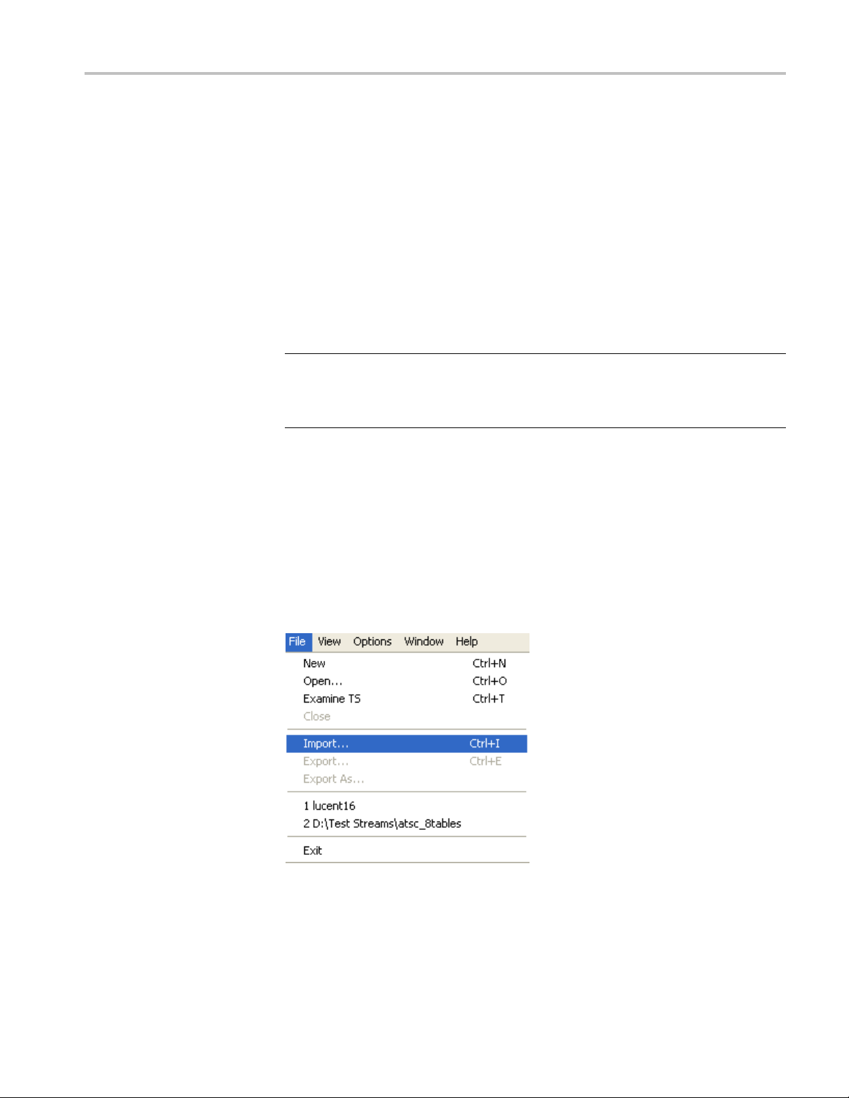
File Menu Options. The following table lists the options available in the initial
File menu.

Multiplexer - Getting Started
Table 1-1: File
Command Function
New
Open Opens an MPEG file for use. The program
Examine TS Opens the Ex
Close Currently disabled
Import...
Export
Export As
ame>
1<filen
2<filename>
3<filename>
name>
4<file
Exit Finishes running the program.
menu options
Opens new multiplex configuration file.
opens the file selection dialog box allowing
you to choos
a brief summary of the stream to be viewed
before it is subjected to full analysis.
Opens a previously saved multiplex
configura
Current
Current
A list o
the program has recently been installed the
list may be empty or hold less than four files.
Selec
e the required file.
amine TS window, which allows
tion file.
ly disabled
ly disabled
f the four most recently used files. If
ting a file name opens that file for use.
View Menu Options. The following table lists the options available in the initial
View menu.
Scripts
Table 1-2: View menu options
Command Function
Interpretation
Event Log
Toolbar Displays or hides the Toolbar.
Status Bar Shows or hides the Status Bar.
Opens the Stream Interpretation dialog box.
This allows the scripts to be used in stream
analysis to be selected.
Opens the Event Log window.
A check mark next to an option indicates that the object is currently visible.
SI scripts are necessary to enable SI table and descriptor data to be analyzed
successfully. Scripts are used to enable analysis of SI data dictated by the various
international standards, for example, MPEG-2, DVB, ATSC, and ISDB.
Essential scripts are installed and enabled using the Stream Interpretation dialog
box. In the absence of any enabled scripts, only the PAT table will be analyzed; all
other data will be presented as private data.
1–6 MTS400 Series Generator Applications User Manual

Multiplexer - Getting Started
Handling Scripts
If a suitably co
custom data will be analyzed when the stream is opened. If the script is not
selected or enabled, the stream will be analyzed, but any custom data will be
reported as either an error in the stream configuration or as an elementary stream
PID.
Scripts can be selected and enabled only when no files are open. The Stream
Interpretation dialog box is available when a file is open, b ut all activity is
disabled.
Note that a script file will not be used for analysis until:
It is present in the Scripts text box in the current analysis mode.
It is succ essfully enabled by closing the Stream Interpretation dialog box
using the OK button.
nfigured script is selected and enabled before a stream is opened,
To open the Stream Interpretation dialog box, with all files closed, select View >
Interpretation. The Stream Interpretation dialog b ox is displayed as shown.
MTS400 Series Generator Applications User Manual 1–7

Multiplexer - Getting Started
The top half of the dialog box is concerned with selecting scripts. The Scripts
text box lists the scripts currently selected. The area adjacent to the text box
is dedic
ated to Expert mode controls.
Selecting Scripts
The selection area of the Stream Interpretation dialog box is best viewed and
used from left to right.
In the Base Standard section, select the MPEG-2, DVB, ATSC, or ISDB standard
for analysis.
The selected standard dictates the availability of the remaining options in the
Regions and Data Standards sections.
In the Regions section, select the country-specificregiontobeaddedtothebasic
standard scripts. If you select None, only the standard scripts are listed in the
ipts text box. The remaining country-specific extensions add extra scripts to
Scr
the current listing. The choice of Regions option dictates the availability of the
options in the Data Standards section.
se Standard
Ba
EG-2 only
MP
DVB Interprets and analyzes
scription
De
Interprets and analyzes
e packets in
th
conformance to the
MPEG-2 standards.
the Transport Stream
ackets according to
P
the specifications of
the DVB and MPEG-2
standards.
gion
Re
None
stom
Cu
None
Custom
KDTG
U
Australian
Nordig
1–8 MTS400 Series Generator Applications User Manual

Multiplexer - Getting Started
Base Standard Description Region
ATSC
ISDB
Interprets an
the Transport Stream
Packets according to
the specificat
the ATSC and MPEG-2
standards.
Interprets and analyzes
the Transport Stream
Packets acc
the specifications of
the ISDB and MPEG-2
standards
d analyzes
ions of
ording to
.
None
Custom
ISDB-T
ISDB-S
ISDB-T (One segment
ISDB-B (Brazil)
ISDB-TB (On
e segment Brazil)
TheDataStandardssectionoffersachoiceofdata-specific scripts.
NOTE. The scripts listed by default reside in the default installation directory
(tektronix\scripts). Other directory locations can b e specified in Expert Mode. All
selections will be retained between sessions.
Checking Syntax
pert Mode
Ex
s are syntactically analyzed when the OK button is selected. They are also
Script
checked when the application is o pened. A fault in the syntax of a script will not
necessarily prevent a stream from being analyzed, but it may result in incomplete
analysis of the stream.
Scripts listed in the Scripts text box will not be used for stream analysis until they
have been successfully checked (the application has been opened or the Stream
Interpretation dialog box has been closed with no script-related error messages
issued).
For an intermediate check of scripts listed in the Scripts text box, select the
Reload Scripts button. This performs the same action as the OK button but
ves the dialog box open.
lea
Syntax errors will be indicated and reported in the Event Log (See page 1-59.).
Expert Mode allows you to select and customize the scripts to be used in
stream analysis and multiplexing. Note that when the expert mode is selected, the
ustom extension option is automatically selected and the management buttons
C
are enabled. In Expert mode, all scripts become a vailable to be added to the script
list. The scripts will be checked and loaded, ready to be used for analysis, when
the OK button is selected.
MTS400 Series Generator Applications User Manual 1–9

Multiplexer - Getting Started
The script management buttons act on the scripts currently listed in the Scripts
text box.
Table 1-3: Script management
Buttons Function
Script files are parsed in the order that they
are listed; in some circumstances this may be
important. To move a file in a list, highlight the file
name and select the Up or Down arrow button as
required. Each press of the button will move the file
up or down one place in the list until it reaches the
top or the bottom.
Add a script to the list: A standard Windows file
selection dialog box is opened. The default file
extension is .scp. S elect the required file. The
selected script will be added to the bottom of the
list. If necessary, move it using the Up and Down
buttons.
Scripts can be loaded from any directory.
Delete the highlighted script.
Change scripts default directory: by default, all
scripts are found in a default directory created
during installation (tektronix\scripts). This button
can be used to set a different default directory.
Note that all scripts supplied by Tektronix in the
default installation are installed in a single directory;
as long as this directory is designated as the default
directory, they will work satisfactorily.
View highlighted script with the associated
application; by default, script files are associated
with the ScriptPad utility.
1–10 MTS400 Series Generator Applications User Manual

Multiplexer - Getting Started
For a script file
associated with a text editor in the Microsoft Windows environment. The MPEG
Test System installation program by default associates a script editing utility
called ScriptPad; you can use another text editor, for example, Microsoft Notepad,
if preferred. ScriptPad is a simple script editor that can be installed with the
MPEG Test System. Scripts can be viewed and edited as required (depending
upon the file
to be viewed successfully, the file extension (.scp) must be
permissions).
MTS400 Series Generator Applications User Manual 1–11

Multiplexer - Getting Started
Opening a Stre
am
OpeninganMPEGStream
When opening a multiplexing, you can, open an existing stream or to open a
previously prepared multiplex configuration file.
When a preparing a stream to be multiplexed, you can:
Create a new null stream (using File > New)
Open an existing stream
Import a multiplexer configuration file
Any file holding a recorded or synthesized sample of a stream that conforms to the
relevant
that the Examine TS option can be used to preview stream. (See page 1-59.)
Some non
parts can be edited usefully. Any tables that are carried in a conformant PID
and have t he correct syntax will appear in the output transport stream, as will
any elementary streams (whether referenced by a table or not) which are in the
input transport stream.
To open a file holding a transport stream, select File > Open. If the required file is
in the list of recent files, open it from the list using the Open File dialog box.
standards can be opened and used as a basis for a new multiplex. Note
conformant streams can be opened, although, only the conformant
Alternatively u se the Ctrl+O keyboard shortcut or drag the file from Windows
Explorer and drop it into the Multiplexer window. A shortcut button is available
on the Toolbar for opening a file.
1–12 MTS400 Series Generator Applications User Manual
Multiplexer - Getting Started
Opening Multiplex
Configuration Files
Any file holding
to the relevant standards, can be opened. Many nonconformant streams can be
opened provided that the PAT, PMT, and MGT tables correctly specify all the
other tables and their PIDs.
Multiplexer is used for generating both conformant and nonconformant streams.
Having generated a nonconformant stream, it may not be possible to successfully
open it again in Multiplexer.
The specification for a new transport stream may be saved to a multiplex
configuration file. This also saves time for opening large MPEG files, since the
specification contains the results of the analysis from opening the original MPEG
file.
NOTE. The multiplex configuration file does not contain a copy of the transport
stream; instead it refers to the original MPEG file by the full path name. Deleting
or moving the MPEG file will result in a dialog box prompting for the n ew
location of the file.
Double-clicking on a *.muxml or *.mux file in Windows Explorer will open the
file in a new instance of Multiplexer.
rting a File. Importing opens a multiplex configuration file and the MPEG
Impo
file on which it is based.
a recorded or synthesized sample of a stream, which conforms
pen a previously exported multiplex configuration file, select File > Import.
To o
If the required file is in the list of recent files, it can be opened from the list to
save using the Import file dialog box.
MTS400 Series Generator Applications User Manual 1–13

Multiplexer - Getting Started
Initial Stream Analysis
Alternatively
Explorer and drop it into the Multiplexer window.
NOTE. Multiplexer reads the name and location of the MPEG file from the
multiplex configuration file and then opens it automatically. The previously stored
changes in the configuration file are applied to the display.
Note that the import dialog box offers a choice of file types: *.muxml, *.mux
and *.*.
The Navigator Tables view window is opened as soon as a file is opened or
imported. The program now starts to analyze the file with the loaded scripts to
mine what tables are present.
deter
,usetheCtrl+I keyboard shortcut or drag the file from Windows
As the file is analyzed, the Top Levels of the Transport Structure diagram are
n in the Navigator window. The right pane in the Status Bar at the bottom of
draw
the program window shows the progress of analysis.
les that are imported require less processing because they were analyzed in the
Fi
session from which they were exported.
1–14 MTS400 Series Generator Applications User Manual

Multiplexer - Getting Started
What to do Next
The file can now b
a new transport stream. Tables, elementary streams, and PIDs are viewed and
selected using the Navigator views. The components of any table selected in the
Navigator views are viewed and selected using the Section View window.
Tables, Programs and PIDs can be added and modified using the wizards or
manually. A selection of menu options is provided to facilitate manipulation of
the data.
The Multiplex menu has options to inhibit and re-enable forced conformance to
the selected standards.
Having manipulated the file, a transport stream can be synthesized to the new
specification by the multiplex engine. The engine is started from the Multiplex
menu or using a toolbar button. The source file is used as reference data by
Multipl
The following illustration gives an overview of the Multiplex process.
exer and the output written to a different file.
e manipulated to form a specification with which to synthesize
MTS400 Series Generator Applications User Manual 1–15

Multiplexer - Getting Started
Open/Import
Any file holdin
sample of a stream that conforms to the
relevant standards can be opened. (See
page 1-74, Open
Importing opens a multiplex configuration file
and the MPEG file on which it is based.
(See page 1-13, Importing a File.)
Transport S
As the file is analyzed, the Top Levels of the
Transport Structure diagram are drawn in the
Transport
(See page 1-14, Initial Stream Analysis.)
Transpor
The file can now be manipulated to act as the
specification to synthesize a new transport
stream. T
are viewed and selected either with the aid
of Wizards or in the Navigator windows.
Output/Export
The Multiplex Engine synthesizes a new
transp
file.
g a recorded or synthesized
ing an MPEG File.)
tructure Demultiplex
Navigator.
t Structure Modifications
he tables and elementary streams
ort stream and writes it to an MPEG
re that the specification for any
To ensu
synthesized stream can be reused, it can be
saved to a multiplex configuration file.
age 1-106, Multiplexing Transport
(See p
Streams.)
1–16 MTS400 Series Generator Applications User Manual

Closing Files
Multiplexer - Getting Started
To close the files, select File > Close. This will close both the MPEG file and any
multiplex configuration file that is open.
A shortcut button is also available on the Toolbar for closing a file, which has
astandardfile close symbol.
If a multiplex configuration file has been edited, and the changes not exported, the
program will ask if the file should be saved.
Select Ye s to export the file, No to close the fi le without saving, or Cancel to undo
the close command and keep the file open.
MTS400 Series Generator Applications User Manual 1–17

Menus and Controls
Menus and Cont
Menu Options
File Men u Options
rols
This section
icons, and user interface.
The following pages describe all of the menu options. Since many of the options
are context sensitive, they will be available only when their function is appropriate
for the selected display or window element. When a menu option is not available,
the option is grayed out.
The following table lists the options available in the File menu.
Table 1-4: File menu options
Command Function
Close Closes the current file. This option is
Examine TS Opens the Examine TS window, which allows
Export...
Export As...
Exit
describes the various menu options, toolbar controls, status bar,
available as soon as analysis starts. If the
wrong file is being opened, or the wrong
options are selected, selecting this option will
abandon the analysis and close the file.
a brief summary of the stream to be viewed
before it is subjected to full analysis.
Exports the current multiplex specification
in a form that can be imported even if it no
longer generates a conformant transport
stream. This option is disabled when no file
is open.
Exports the current file, as above, and allows
a different file name to be specified. This
options is disabled when no file is open.
Closes any file that is open and terminates
the program.
1–18 MTS400 Series Generator Applications User Manual

Menus and Controls
Edit Menu Options
The following t
able lists the options available in the Edit menu.
Table 1-5: Edit menu options
Command Function
Add
Modify Edits the information in the currently selected
Delete Deletes the item currently selected.
Cut Cuts the current selection from the Window.
Copy Copies the contents of the current selection
Paste
Export Payload
Export Elementary Stream
Export Section Data
Import Section Data Imports SI data from a file and analyzes it.
Adds a table/section/loop to the currently
selected item in the Navigator or Section
View.
field or item.
to the clipboard.
Pastes data from the clipboard to the part of
the transport structure that holds that type
of data.
Extracts and exports the payload of the
source transport stream PID in the form of a
simple data file.
Removes the transport stream PID and
PES headers and exports the remaining
information as a simple data file.
Extracts and exports section data. The
created file can be imported as ES using
Multiplexer’s Add function or as SI using the
Import Section Data option (see next option).
The section is added to the Navigator view.
View Menu Options
The following table lists the options available in the View menu.
ble 1-6: View menu options
Ta
mmand
Co
Interpretation
Section View Opens the window and displays the table
Event Log
Component Bit rate Displays a graphical comparison of the
nction
Fu
isplays a read-only dialog box for viewing
D
scripts that have been selected for analysis.
See Initial Menu Options, (See page 6-2.)
section currently selected in the Navigator
view.
Displays the list of events that are recorded
in the Event Log.
stream bit rates.
MTS400 Series Generator Applications User Manual 1–19

Menus and Controls
Table 1-6: View menu options (cont.)
Command Function
Component Duration Displays a graphical comparison of the
stream component durations.
Available Bit rate
Properties
Zoom In Zooms in the Available Bit rate and
Zoom Out Zooms out from the Available Bit rate and
Synchronize Synchronizes zoom levels of the Available Bit
Show Cursor Shows or hides the cursor in the Available
Toolbar
Status Bar Shows or hides the Status Bar.
Displays a graphical view of the bit rate in
the stream.
Opens a properties dialog box for editing
the currently selected item in the Transport
Navigator window.
Component Duration views.
Component Duration views.
rate and Component Duration views (toggle).
Bit rate and Component Duration views.
Shows or hides the Toolbar.
Options Menu Options
The following table lists the options available in the Options menu.
Table 1-7: Options menu options
Command Function
splay Filter
Di
Single Section View Selects single or multiple section view. When
Program Wizard Invokes the Program wizard.
Transport Wizard Invokes the Transport wizard.
H264 Bitrate detection settings
Opens the SI Filter dialog box.
disabled, multiple section views can be
pened.
o
Opens the H264 stream bitrate detection
settings dialog box. (See page 1-38.)
1–20 MTS400 Series Generator Applications User Manual

Menus and Controls
Multiplex Menu Options
The following t
able lists the options available in the Multiplex menu.
Table 1-8: Multiplex menu options
Command Function
Start Starts the Multiplex Engine, to synthesize a
new transport stream file.
Stop Aborts multiplexing. The output file is closed
and contains all of the data synthesized
up to the point where the multiplex engine
stopped. This option is available only while
the Multiplex Engine is running.
Standard Mode Enforces conformance to the selected
standards when editing some fields that can
be generated automatically.
Expert Mode
Report
Seamless When enabled, the program specified in
Seamless Settings Opens a dialog box in which the Make
Playout When enabled, generates and captures
Playout Settings Opens the Playout Settings dialog box in
Loop
Update
Inhibits the above conformance checking so
that nonconformant files may be created.
Provides the option of printing all or part of
the transport structure to either a file or a
printer.
Seamless Settings is processed and made
seamless.
seamless parameters are specified.
MPEG-2 transport streams that are compliant
with ATSC, DVB , and ARIB standards.
which path of the MPEG player application
and the folder where the temporary files are
specified.
Sets whether the stream is output using the
looping method.
Opens a dialog box in which the parameters
in a stream are updated when looped.
he following table lists the options available in the Window menu.
Window Menu Options
T
Table 1-9: Window menu options
Command Function
Cascade Cascades the open windows when Options > Single
Section View is disabled.
Tile
Tiles the windows horizontally when Options >
Single Section View is disabled.
MTS400 Series Generator Applications User Manual 1–21

Menus and Controls
Table 1-9: Window menu options (cont.)
Command Function
Arrange Icons
1 <window title>
2 <window title>
3 ... etc.
Aligns icons of any minimized windows at the
bottom of the program’s main window.
Makes the named window active, putting it on top of
any window that had been hiding all or part of it.
Help Menu Options
Toolbar
Status Bar
The following table lists the options available in the Help menu.
Table 1-10: Help menu options
Command Function
About Multiplexer
Opens a dialog box that displays the program version
number and license number.
Toolbars provide a set of convenient shortcuts for the more frequently used menu
options. The buttons are context sensitive and are enabled or disabled depending
upon the currently highlighted view or the action being performed.
The Toolbar can be hidden from view by selecting View > Toolbar.
The Status Bar may be hidden from view, but when displayed it is always at the
bottom of the main window. For example:
The following information is displayed from left to right on the Status Bar:
Message Field. Provides a description of any button or menu option over which
the cursor pointer is placed. Other noncritical messages may also be shown.
Filter Status. Indicates the status (On/Off) of the SI Filter.
1–22 MTS400 Series Generator Applications User Manual

Menus and Controls
Standard Inter
processed: MPEG-2, ATSC, DVB, or ISDB.
TS Rate & Duration. Shows the transport stream rate and the duration at that rate.
A default rate is displayed during initial analysis.
User Mode. S
mode prevents changes to certain fields. The Expert mode enables editing.
Processing Status. Indicates the progress (%) during initial analysis and
multiplexing.
Processi
multiplexing.
The Stat
NOTE. The status bar (Standard interpretation) displays ISDB-T SS whenever the
ISDB interpretation with Single segment extension is selected.
pretation. Indicates the selected standard with which the file is
hows the User mode selected: Expert or Standard. The Standard
ng Progress. Indicates the progress during initial analysis and
us bar can be hidden from view by selecting View > Status Bar.
MTS400 Series Generator Applications User Manual 1–23

Menus and Controls
User Interfac
e
Icons
NOTE. The Menu Bar contains the complete selection of options available in
the Multiplexer. Shortcuts to options are available through the toolbar and
context-sensitive shortcut menus.
Icons are used throughout the Multiplexer user interface to help you to identify
components and make visual links with toolbar shortcuts and menu options.
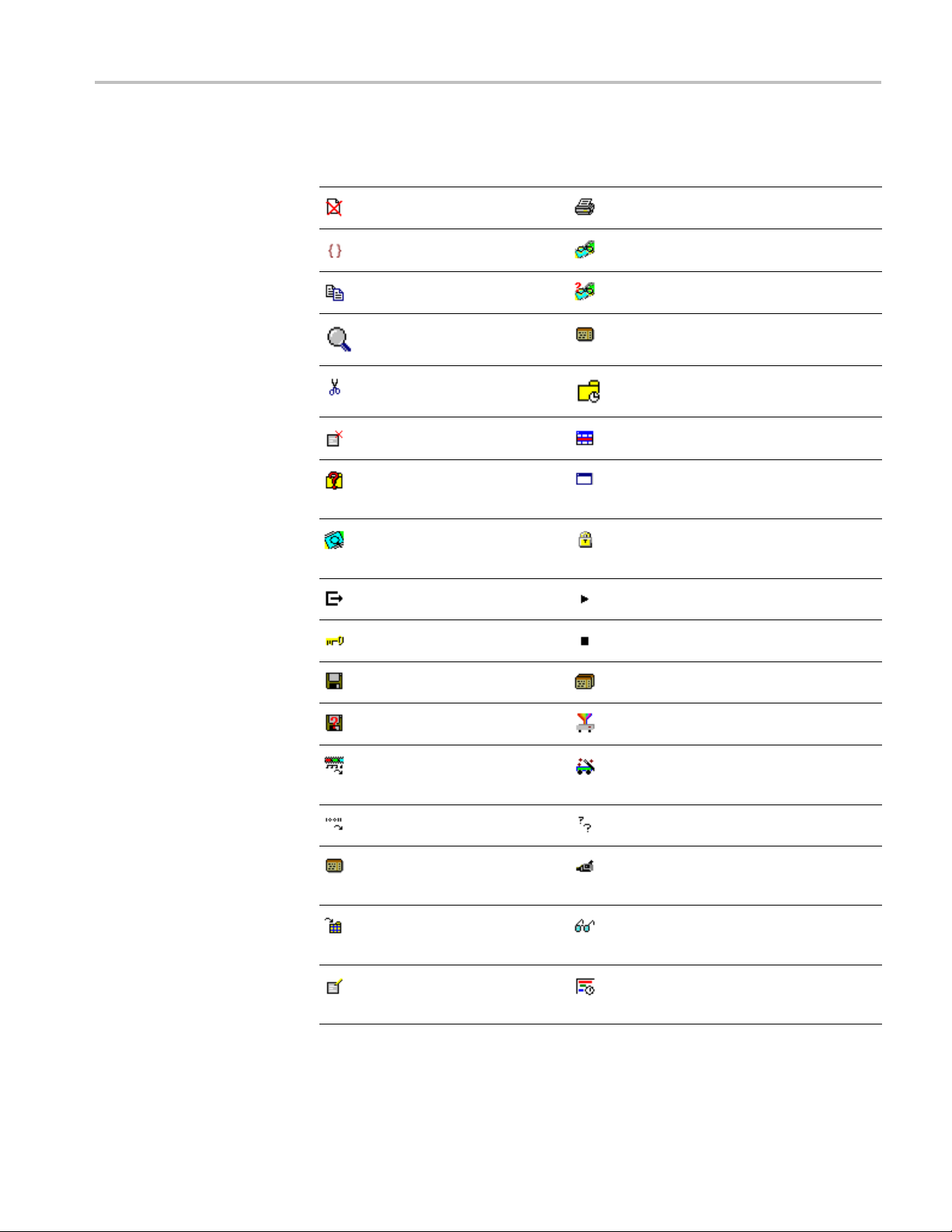
The following table lists all
the icons used.
Table 1-11: Icons
Icon Description Icon Description
About
Multiplexer
Add Program
Audio
stream
Bit field
Program
Group
Program
Wizard
Properties
1–24 MTS400 Series Generator Applications User Manual
Menus and Controls
Table 1-11: Icons (cont.)
Icon Description Icon Description
Close
Container/Loop Seamless
Copy Seamless
Current
selection
Cut Section
Report
Settings
Section
timing
Delete
Display
Filter dialog
box
Examine
Transport
Stream
Exit
Expert
mode
Export Table
Export As Transport
Export
Elementary
Stream
Export
Payload
Export
Section
Data
Import
Section
Data
Modify
Section View
Single
window
Standard
mode
Start
Stop
Stream icon
Transport
Wizard
Unknown
Video stream
View Event
Log
View
Component
Duration
MTS400 Series Generator Applications User Manual 1–25
Menus and Controls
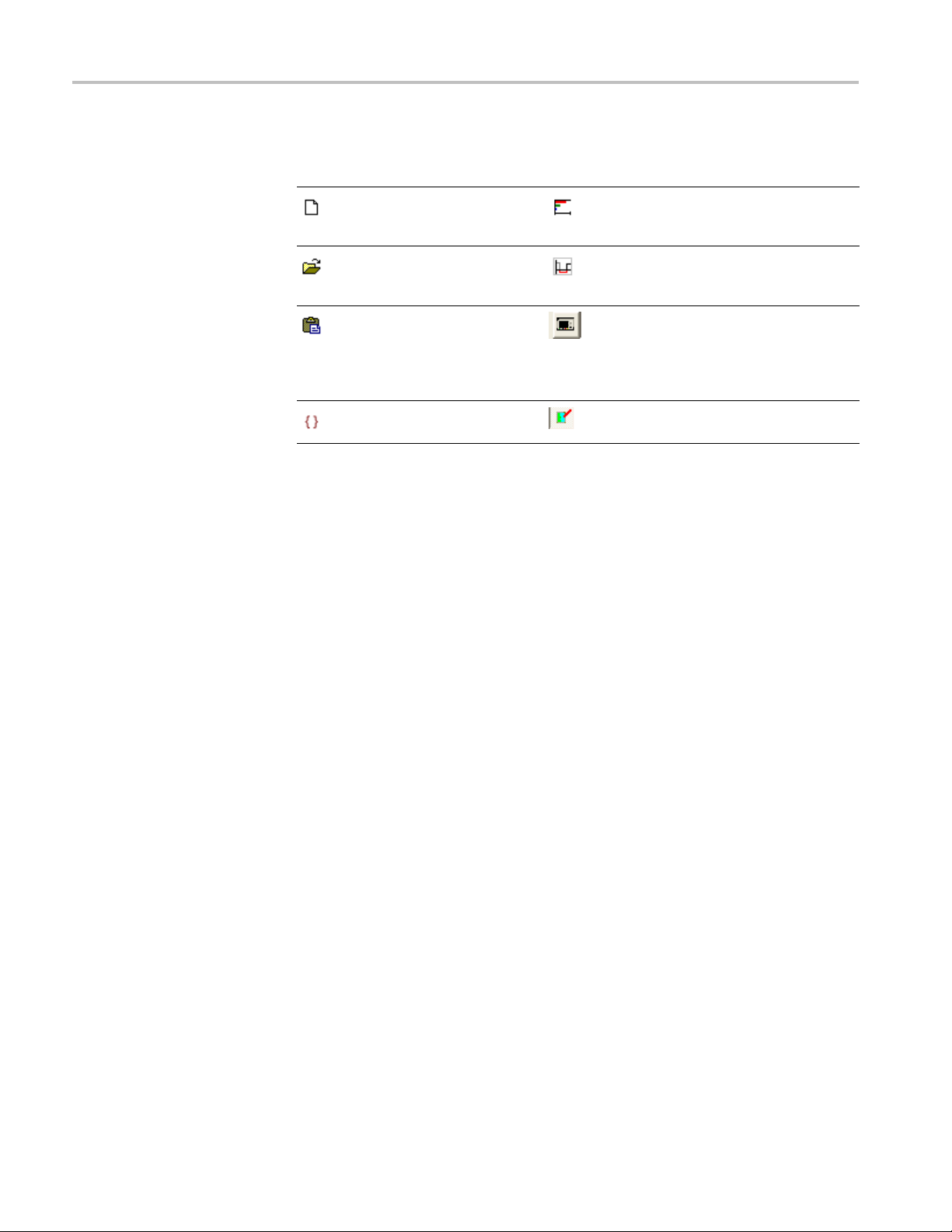
Table 1-11: Icons (cont.)
Icon Description Icon Description
New View
Component
Bit rate
Open
Paste Playout-
Loop Update
View
Available Bit
Rate
Playout the
created TS
using Mpeg
Player
Cutting
and Pa sting
Table types, sections, and PIDs can be cut, copied, and pasted using the Windows
clipboard. Only one selection can be held on the clipboard at a time. Alternatively,
a selection can be dragged and dropped using the mouse.
Cutting a Selection to the Clipboard. A selection (table type, section or PID)
can be deleted and automatically placed on the Windows clipboard. It can then
be pasted to a different file or back into the current file. Highlight the selection
in the Navigator Tables or PIDs view and select Edit > Cut or use the Ctrl+X
keyboard shortcut.
Copying a Selection to the Clipboard. A selection (table type, section or PID) can
be copied to the Windows clipboard. From the clipboard, it can be pasted to a
different file or back into the current file.
Highlight the required selection in the Navigator Tables or PIDs view and then
select Edit > Copy or use the Ctrl+C keyboard shortcut.
Pasting a Selection from the Clipboard. More than one instance of Multiplexer
an run concurrently on a machine. A selection (table type, section, or PID) can
c
be pasted from the clipboard into any open transport stream file. The contents of
the clipboard are not affected by the paste operation, so the section can be pasted
to many files and more than once to the same file.
Activate the Navigator Tables or PIDs view of the required transport stream file
(that is, in an instance of Multiplexer). Then select Edit > Paste or use the
Ctrl+V keyboard shortcut.
The section or version is always appended to the end of the list under the
appropriate table. Program or version numbers are automatically created. If the
table is not present in the multiplex configuration, it will be created automatically.
1–26 MTS400 Series Generator Applications User Manual

Menus and Controls
Dragging and Dropping
A concept famil
highlighted by clicking on them with the mouse and then dragged and dropped to
a new location, either in the same application or across applications.
In Multiplexer, the main uses of the drag and drop feature are to modify
multiplexes and to build new ones.
Elements can be dragged within Multiplexer, or from the Multiplexer Browser,
Windows Explorer or other instances of Multiplexer.
The program references and the numbering will be automatically added and/or
updated when a new program is dropped onto the Navigator Programs view.
NOTE. Only the MPEG aspects of the transport structure are updated. Tables
specific to DVB and ATSC are not updated.
Manipulation in Program View.
The following manipulations are available in the Program view:
When us
dragged. The program can be dropped only on the transport stream node
of the Program view.
iar to Windows users is "drag and drop" in which files can be
ing the Navigator Program view, a program can be copied or
Only the standard MPEG elements are copied, namely the PAT entry, the
PMT section and the elementary streams. Standard dependent information is
not copied, for example, DVB SDT.
When a conflict occurs with the target, new values will be allocated for the
Program and PID numbers.
Elementary streams can also be dragged and dropped between the Program
Views. They can be dropped only onto the elementary stream root node.
An elementary stream may have a stream type, a component tag and
descriptors associated with it; this informationisretainedduringadragand
drop in the program view. The program view displays this information when
the properties dialog box is activated.
MTS400 Series Generator Applications User Manual 1–27

Wizards
Wizards
In the Navigator Programs view, wizards provide you with a step-by-step approach
to building streams to be multiplexed by offering defaults for PSI/SI and the
opportunity
in the Interpretation dialog box will dictate which PSI/SI components are offered.
to include user-selected programs. The standard previously selected
Wizard
Controls
There are tw
Other minor wizards may be opened by these major wizards or they may
be opened in a new window to facilitate specific tasks, such as adding EIT
information. When configuring a new multiplex, the Transport Wizard is opened,
followed by the Program Wizard; although, on completion of the Transport phase,
an opportunity to exit the wizard process you have before the Program Wizard
opens. F
At their most basic level, wizards open, in a logical order, the property dialog
boxes th
The following paragraphs provide a step-by-step description of the wizards.
The following control buttons are provided on the wizard dialog boxes where
relevant:
Next Retai
Back Disc
Cancel
ish
Fin
o major wizards: the Transport Wizard and the Program Wizard.
or some detailed operations, only the appropriate wizard can be opened.
at are available when building a stream manually.
n changes made using this dialog box
and move to next dialog box.
ard changes made using this dialog and
return to the previous dialog box.
the wizard and discard all changes.
Exit
t the wizard and implement all changes.
Exi
Transport Wizard
Toolbar icon:
The Transport wizard allows you to easily create a basic stream populated with
the PSI/SI necessary to hold program information. It may also be opened when
PSI/SIistobeaddedtoanexistingstream.
1–28 MTS400 Series Generator Applications User Manual
Wizards
Creating a New Transport
Stream
The following s
NOTE. When the Transport Wizard is used to populate a new stream, if the
defaults in the various dialog boxes are retained, then the resulting stream will
conform to the selected standard.
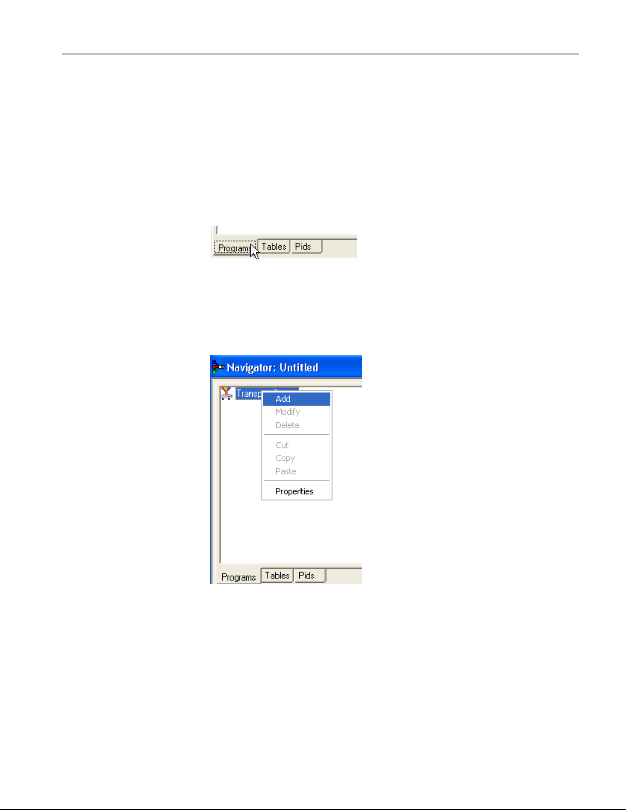
1. To open a new file, select File > New.
2. Select the Program tab in the Navigator view.
3. Select and highlight the Transport Structure element. At this stage of creating
a new stream, this will be the only element visible in the Program Navigator
view.
4. Select Add from the shortcut menu. The Transport Stream Settings dialog
box appears.
teps show the screens used in the creation of a DVB stream.
MTS400 Series Generator Applications User Manual 1–29

Wizards
The Transport S
stream identity (part of the PAT section) and version. Adjustments can also be
made to the PAT timing, if required, by selecting the PAT button.PAT timing see Editing PSI/SI Table Properties.(Seepage1-83.)
tream Settings dialog box allows you to set up the transport
NOTE. You cannot add a PAT with the ISDB interpretation and Single segment
extension selected. When y ou click Add, the Add a Program wizard is displayed
instead of the Transport Stream Settings.
5. In the Transport Stream Settings dialog box, click Next to move to the
Optional Tables dialog box. This dialog box allows you to include and
configure basic PSI/SI information if required.
1–30 MTS400 Series Generator Applications User Manual

Wizards
6. Select the check box next to each table to add the table name. The table name
is added to the graphical representation on the left and the associated buttons
are also enabled. You can modify the settings of the table such as, timing.
For NIT, TOT, and TDT Timing information, see Editing PSI/SI Table
Properties.(See page 1-83.)
MTS400 Series Generator Applications User Manual 1–31

Wizards
NIT Settings
7. In the Optional
Network Information Table (NIT). The Set up the NIT dialog box appears.
8. Enter or select the required values and click OK.
NOTE. If a Delivery System other than Undefined is selected, an additional
settings dialog box becomes available, specific to the Delivery System chosen.
Tables for the Stream dialog box, click Settings for the
1–32 MTS400 Series Generator Applications User Manual

Wizards
9. Select Next to m
dialog box allows you to review the changes made by the wizard before
confirming the process. The process can be cance lled, thereby losing all
changes, by selecting the Cancel button.
At this stage in the creation of a new multiplex, if you want to add programs,
leave the Add Program Wizard check box enabled and select Next. If you want to
add them by some other means, clear the Add a Program Wizard check box. The
Next b
implement all changes.
utton label will change to Finish, which allows you to exit the wizard and
ove to the Transport Wizard Complete dialog box. This
Program Wizard
When t
with the new PSI/SI.
Toolbar Icon:
The Program Wizard allows you to add programs as required to a stream that is
already populated with basic PSI/SI. Each use of the Program Wizard allows
the addition of one program. Adding more programs requires the wizard to be
opened each time.
If a new stream is being created, the Transport Wizard offers an opportunity
to open the Program Wizard. Alternatively, in the Navigator Programs view,
highlight the Programs node and select Add from the shortcut menu.
he Transport Wizard has closed, note that the Navigator views are updated
MTS400 Series Generator Applications User Manual 1–33

Wizards
Adding a Program to a
Transport Stream
To add a program
NOTE. When the Program Wizard is used to add programs to a stream, if the
defaults in the various dialogs are retained, the resulting stream will conform
to the DVB standard.
1. When you open the Program Wizard, either as a continuation of c reating a
new stream or as an attempt to add a new program, a dialog box similar to that
shown belo
to the transport stream, follow these steps:
w is displayed:
The values placed automatically in the three displayed fields will be the next
in the sequence of programs. (In the example screen, the stream contains n o
prior programs, therefore this is program number 1. PID 32 is used because
is the first free PID after the reserved PSI/SI PIDs.)
that
PMT Timing - see Editing PSI/SI Table Properties.(Seepage1-83.)
2. Select Next to move to the Add Service Description dialog box.
NOTE. If ISDB interpretation with Single Segment extension is selected the
ogram number starts from 8 (default). However, you can enter numbers from 1
pr
to 7.
1–34 MTS400 Series Generator Applications User Manual
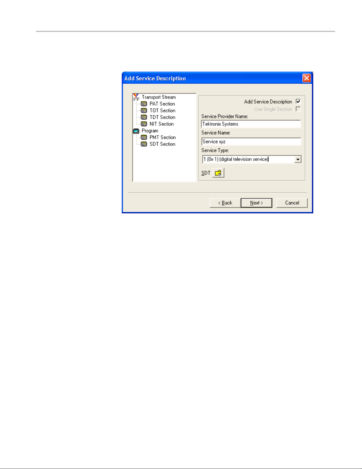
Wizards
Service Description Dialog
Box
The Service Des
be associated with a program.
3. By default, the Add Service Description check box is clear. W hen it is
enable
Service Type selected from the drop-down list. If no details are provided, the
section will still be created but the relevant descriptors will be empty.
cription dialog box allows you to identify the Service Provider to
d, a Service Provider Name and a Service Name must be entered and a
Enabling the Use Single Section check box will cause the SDT descriptors to
be added to the existing SDT section. If the stream contains no SDT section,
the check box is disabled.
SDT timing - see Editing PSI/SI Table Properties. (See page 1-83.)
4. Select Next to move to the Program Content dialog box.
MTS400 Series Generator Applications User Manual 1–35

Wizards
Program Content Dialog
Box
This dialog box
with the program in the final multiplex.
5. Select Add to display the Add Program Stream dialog box. This dialog box
allows you to identify elementary streams to be included in the new multiplex.
You must specify the PID and Stream Type of the new stream. A Component
Tag can also be allocated.
allows you to compile a list of elementary streams to be associated
If the Component Tag is enabled, it can be referenced by other tables, for
example, the Event Information Table.
1–36 MTS400 Series Generator Applications User Manual

Wizards
The dialog box c
stream, its timing within the multiplex, and whether it should be carrying
aPCRPID.
6. Select a Stream Type from the drop-down list. This will be the Stream Type
allocated to the stream in the new multiplex.
NOTE. The Stream Type drop-down list displays the previously selected stream as
the default type.
7. Allocate a PID Number in which the elementary stream is to be carried.
onsists of three tabbed pages that specify the source of the
8. Enable the Component Tag check box, if required. Enter a Component Tag
number (0-255) in the enabled field.
Source Tab. Use the Source tab of the Add Program dialog box to select and
ecify elementary streams to be included in the new multiplex.
sp
MTS400 Series Generator Applications User Manual 1–37

Wizards
9. Enter an elementary stream File Name. You can enter it directly or use the
Browse button to open a standard Windows file selection dialog box.
10. Select the File type of the selected stream from the drop-down list.
If you se
displayed in the Bit rate field.
If you se
If the video stream contains HRD information, the b it rate is automatically
calcul
Streams.)
If the
calculated manually. (See page 1-40, Calculating the Bit Rate for H.264
Non-HRD Streams.)
When the selected file type does not match with the selected file name, an
error message is displayed and you will have to reselect the correct file type.
11. If you select H.264 video with SEI stream, a Suppress PTS/DTS insertion
check box is displayed. Select this check box to suppress the PTS/DTS
insertion.
lect MPEG-2 video, the bit rate is detected automatically and
lect H.264 video, the Bitrate Detection dialog box is opened.
ated. (See page 1-38, Calculating the Bit Rate for H.264 HRD
video stream does not contain HRD information, the bit rate must be
Calculating the Bit Rate for H.264 HRD Streams. If HRD information is detected
in the stream, the maximum bit rate is calculated automatically and displayed
in the Bitrate Detection dialog, as shown in the following screen capture. You
1–38 MTS400 Series Generator Applications User Manual
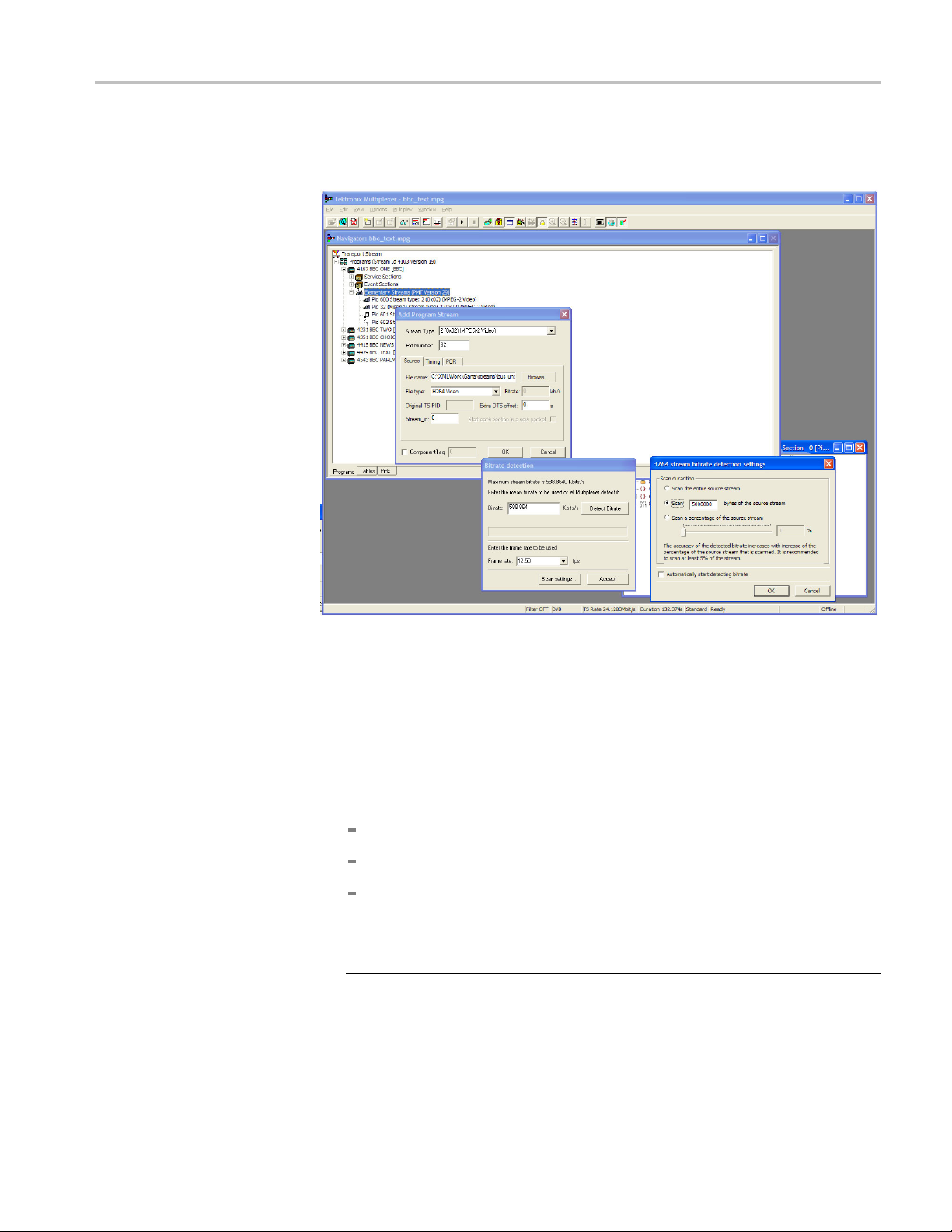
Wizards
can override th
selecting Detect Bitrate.
e calculated bit rate, either by entering a value manually or by
12. When the displayed bit rate is satisfactory, select Accept.
13. To alter the settings used for bit rate detection, before the bit rate is detected,
select Scan Settings.
When you select Scan Settings,theH264 Stream Bitrate Detection Settings
dialog box is displayed.
The H264 Stream Bitrate Detection Settings dialog box has three Scan
Duration options. Select one of the following options to proceed:
Scan the entire source stream
Select the number of bytes in the stream to scan
Select a percentage of the stream to scan.
NOTE. The accuracy of the detected bit rate increases with the percentage of
the source stream that is specified.
The chosen setting will be used in subsequent calculations. Select
Automatically start detecting bitrate to use the selected setting.
MTS400 Series Generator Applications User Manual 1–39

Wizards
Calculating th
detected in the stream, you must either enter a value manually or use the Detect
Bitrate functionintheBitrate Detection dialog box.
e Bit Rate for H.264 Non-HRD Streams. If no HRD information is
Timing Tab. The Timing tab of the Add Program dialog box is used to specify the
portion o f the new multiplex that the selected stream will use. The default start
time is set to 0.002 s.
1–40 MTS400 Series Generator Applications User Manual
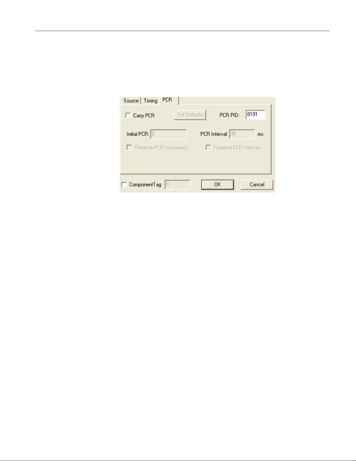
Wizards
12. Complete the fie
to be carried throughout the new multiplex, looping if necessary.
PCR Tab. The PC
whether PCR information s hould be carried with the selected elementary
stream or in a separate associated PID.
13. If the PCR is to be held in an associated PID, disable the Carry PCR check
box and enter a PCR PID number.
lds as required. The default settings assume that the stream is
R tab of the Add Program dialog box is used to specify
14. If the PCR is to be carried with the stream, enable the Carry PCR check box
and complete the remaining fields as required.
Set Defaults returns the settings to their initial values.
15. Select the OK button to complete adding an elementary stream to the listing
in the Program Wizard.
16. More streams can be added using the Add button. Listed streams can be
deleted using the Delete button. Details of listed streams can be modified
using the Update button.
MTS400 Series Generator Applications User Manual 1–41

Wizards
This completes the addition of one or more program streams.
17. Select Next to move to the Event Information dialog box.
For more details about the fields on these tabs, refer to Adding an Unreferenced
Elementary Stream.(Seepage1-88.)
Event Information Dialog
Box
The Event Information dialog box allows youtoaddthePresentandtheFollowing
event information.
18. If the Event Information Table (EIT) is to be included in the multiplex, enable
the Event Information Table check box.
19. Enable the Present and Following check boxes as required.
1–42 MTS400 Series Generator Applications User Manual

Wizards
Present/Following timing - For more information on Present/Following
timing, see Editing PSI/SI Table Properties.(Seepage1-83.).
20. Use the Settings buttons to open the Present/Following Events dialog box.
21. In the Present/Following Events dialog box, click Add. The Event dialog box
appears. Add and specify events as required.
MTS400 Series Generator Applications User Manual 1–43

Wizards
22. Click OK.
23. In the Event Information dialog box, click Next to move to the Program
Complete dialog box.
Program Complete Dialog
Box
The Program Complete dialog box provides you with a summary of the created
Transport Structure.
24. To c onfirm and implement the Transport Structure, s ele ct the Finish button.
Note that the proposed structure is created in the Navigator views.
This completes the procedure of adding a program to a transport stream using the
Program Wizard.
1–44 MTS400 Series Generator Applications User Manual

Views
Navigator Views
Views
Multiplexer contains a number of views, which are displayed in the working area
of the user interface. All of the views can be manipulated using conventional
Windows tech
the edges of the UI or floated independently of the Multiplexer window. The
Section view can be manipulated within the Multiplexer window, including tiling
and cascading where multiple Section views are displayed.
Each available view displays a different aspect or level of detail of stream analysis
and manipulation.
The Navigator view contains three subviews or tabs: Programs, Tables, and PIDs.
niques. The Navigator and Error Log views can be docked against
Program Views
The Na vigator Programs view extracts and displays system information that is
relevant to programs. Information that is not directly related to programs (for
example, NIT), or that has not been incorporated into a program (for example,
elementary streams not listed in a PMT) will be omitted from the Program view.
The system information is still available for viewing in the Navigator Tables
Ds views.
and PI
MTS400 Series Generator Applications User Manual 1–45

Views
It is recommended that manipulation of programs and elementary streams should
take place from the Program view.
1–46 MTS400 Series Generator Applications User Manual

Views
Tables View
TheTablesview
Information Protocol (PSIP), Service Information (SI), and Program Specific
Information (PSI) tables. More detailed payload information can be examined and
edited, for a selected section of a table, using the Section View.
displays a high-level structure of the Program and System
SI/SI information that the program cannot confidently analyze, will be
Any P
showninthePIDsview.
MTS400 Series Generator Applications User Manual 1–47

Views
PIDs View
The PIDs view di
in ascending numerical order.
splays the PIDs contained in the stream. The PIDs are displayed
PSI/SI table types are identified in the section nodes of System Information nodes.
Elementary strea m PIDs are identified by source and type where possible.
1–48 MTS400 Series Generator Applications User Manual

Section View
Views
The Section View displays the contents of the currently selected section in any
of the Navigator views.
The Section view is dynamic in that it will be instantly refreshed if a new section
is highlighted in the Navigator view. If no section is selected, the Section view
be blank.
will
Thelockicon-
icates that those items have restricted access due to the mode of user operation:
ind
Expert or Standard.
MTS400 Series Generator Applications User Manual 1–49
- adjacent to certain elements of the table in the Section view

Views
Syntax of a Section
The following d
iagram shows a section from a Master Guide Table (MGT).
The syntax specified for an MGT in the ATSC standard A65 is:
master_guide_table_section () {
table_id
section_syntax_indicator
private_indicator
zero
section_length
table_id_extension
reserved
version_number
current_next_indicator
section_number
last_section_number
protocol_version
tables_defined
1–50 MTS400 Series Generator Applications User Manual

Views
for (i=0;i<tab
table_type
reserved
table_type_PID
reserved
table_type_version_number
number_byt
reserved
table_type_descriptors_length
for (k=0;k<N;k++)
}
reserved
descriptor tag
descriptors_length
for (I = 0;I< N;I++)
CRC_32
}
The terms used in this manual to describe the components, represented by nodes,
in the structure diagram are:
les_defined;i++) {
es
descriptor()
descriptor()
ainer. A term used to describe a node in the structure diagram
Cont
which may contain zero, one or more loops. It is analogous to the for
(i=0;i<loops_defined;i++) statement used to describe the syntax of a table in the
ATSC standards. The container is always preceded by a field which specifies the
number of loops it contains.
oop. Describes a data structure composed of a specified set of fields and
L
subordinate loops. The structure diagram s hows each loop as a node with the
fields and subordinate loops as children. Each loop node in the section view
represents one iteration of the loop body (the contents of the curly braces { }) in
the syntax spec i fi ed by the ATSC standards.
Field. Fields are referred to in the standards documents as both data items and
fields. They are the smallest pieces of information that make up a table.
For example, taking an MGT that defines three tables, the Section View represents
the syntax and contents of the Tables container like this:
The loop for the first table, EIT-0 has been expanded to show the fields and
subordinate loops that it contains.
MTS400 Series Generator Applications User Manual 1–51

Views
Syntax of a Multiple String
Structure
The ATS
Structure. An instance of this structure may contain zero or more strings and each
string may contain zero or more segments. The syntax specified for a Multiple
String Structure in A65 is:
multiple_string_structure () {
}
C standard A65 defines a data structure called the Multiple String
number_strings
for (i= 0;i< number_strings;i++) {
ISO_639_language_code
ber_segments
num
for (j=0;j<number_segments;j++) {
compression_type
mode
number_bytes
for (k= 0;k<number_bytes;k++)
ompressed_string_byte [k]
c
}
}
1–52 MTS400 Series Generator Applications User Manual

Views
Using the notat
the Multiple String Structure in the same way as any other data structure. For
example: an Extended Text Table (ETT) carries its extended_text_message in a
Multiple String Structure. The default view of a section of an ETT in the Section
View looks like this:
Section View displays a node for the extended_text_message (with as much as
le of the first segment) from the first string.
possib
ion of container, loop, and field nodes, the Section View represents
Expanding the node reveals a number_strings field which specifies the number of
gs and a container which holds them (strings):
strin
The number_strings field shows that there are two strings in this example.
Expanding the strings container shows the loop for each string. From this it can
be seen that both strings are in English.
Expanding each of the strings reveals the number of segments (number_segments)
that make up each string and a segments container. Similarly, expanding the
segments container reveals segments.
MTS400 Series Generator Applications User Manual 1–53

Views
Expert and Standard
Modes
The contents of each segment loop define what compression and character set are
used, followed by the actual text. The text is held in the compressed_string field.
The Multiplexer has two modes of operation for conformance checking when
editing table contents. These are selected from the Multiplex menu. The checks
that affect the Navigator are:
dard Mode. Prevents changing the PID of a table whose PID number is
Stan
specified in the standard, for example, PID 0x0 carries the PAT.
Expert Mode. A warning is displayed and confirmation requested before changing
thePIDofatablewhosePIDnumberisspecified in the standard.
1–54 MTS400 Series Generator Applications User Manual

Views
An adjacent check mark indicates the mode selected. The mode is also indicated
on the Sta
tus Bar.
In the Section View a padlock symbol
that can
show the same tables in Standard and Expert mode.
not be edited in the current mode. For example, the following screens
is displayed adjacent to all of the fields
MTS400 Series Generator Applications User Manual 1–55
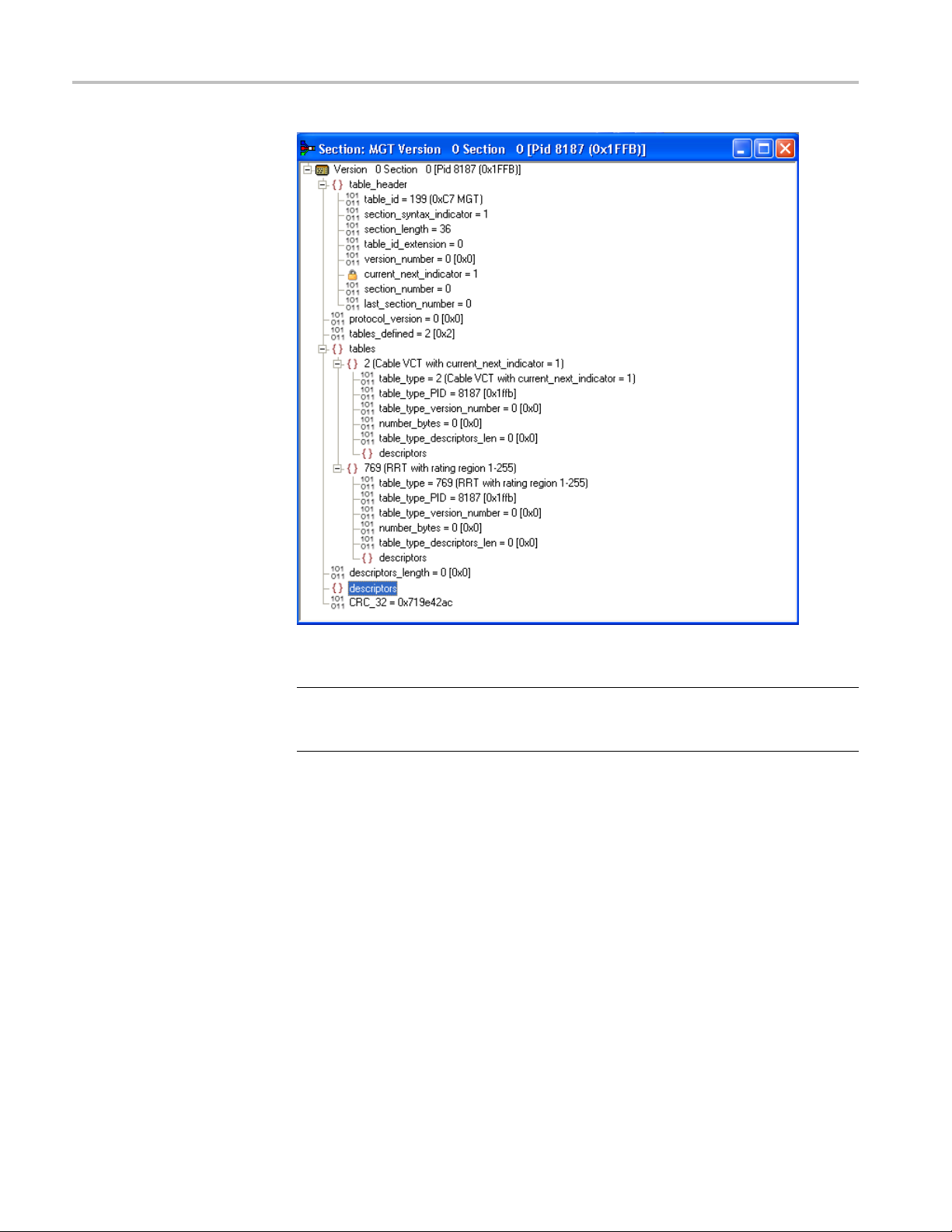
Views
Figure 1-1: Expert mode
NOTE. T
be edited. This is because the field is affected solely by the Section Properties
concerned with Version Timing. (See page 1-84.)
The selected mode is also reflected in the Wizards that are used to create of
multiplexes. Elements that are restricted in the tables in Standard mode will also
be restricted in the relevant wizard. Similarly, elements that are enabled in Expert
mode will be enabled in the associated wizard.
he current_next_indicator in both Standard and Expert mode cannot
1–56 MTS400 Series Generator Applications User Manual

Views
Figure 1-2: Standard mode
NOTE. T
padlock icons.
he Section View may need to be closed and reopened to update the
MTS400 Series Generator Applications User Manual 1–57

Views
Structure Dia
gram Manipulation
A tree diagram, with the "root node" or highest level component at the top
represents the Transport Structure. A square box indicates components that
contain more
information beneath them in the structure.
ing on the box does not select that node. It only shows or hides the next
Click
level of detail under that node.
e node has a minus sign in the box the level of detail below it is currently
If th
displayed. The lower level(s) may be hidden by clicking the mouse pointer on
the box.
If the box contains a plus sign, there is another level in the node that is currently
hidden. Click the mouse pointer on the box to display the next level of information
under the node.
Components that are connected to a branch of the tree without a square box are
leaf nodes; the accompanying icon indicates the node type. They display the
lowest and finest level of detail available in this diagram. These are either a
Section of a Table or a PID.
Fields in the Section view that cannot be edited directly are indicated by a padlock
symbol,
the Multiplex menu. It can be reenabled by selecting Standard Mode.
. This protection can be switched off by selecting Expert Mode from
1–58 MTS400 Series Generator Applications User Manual

Event Log
Views
Messages about significant events are written to the Event Log from the time a
file is first opened. You can open the Eent Log for viewing at any time during or
after the initial analysis. When the initial analysis is done, the mean transport rate,
bit rate for each PEES PID, and a Demultiplex c omplete message are written
in the Event
The start and end times for generating a ne w transport stream are shown by the
Multiplexer started and Multiplexer completed messages.
Log.
Note that when demultiplexing and multiplexing streams, the bit rate at which the
demultiplex or the multiplex is performed is given in the Event Log. This is in
addition to the stream bit rate derived from the stream itself.
When synthesizing a new transport stream any errors or warnings about the new
stream are written to the Event Log between the start and completed messages.
The Category column indicates the type of event. The subject or time of the
event is shown in the Reference column and the details are given in the Comment
umn.
col
The c omplete text can be copied onto the Windows clipboard, using the Copy
ion from the shortcut menu. The text can also be cleared with the Clear
opt
command. Both commands are also available from the Edit menu.
Examine Transport Stream Window
The Examine Transport Stream (Examine TS) window (File > Examine TS)
performs two main functions within the Multiplexer:
It allows you to take an overview of a transport stream before subjecting it
to full analysis.
It allows tables and programs to be dragged and d ropped from the examined
stream to the file that is currently open in Multiplexer.
MTS400 Series Generator Applications User Manual 1–59

Views
Menu Bar
File Summary
The Examine TS window menu bar contains only two items: File and Edit.
File Menu. The following table lists the items in the File menu.
Table 1-12: Examine TS - File menu options
Command Function
Open... Analyzes and opens the selected file in the
Examine TS window. Closes the current file.
Close Closes the Examine TS window.
Edit Menu. The following table lists the items in the Edit menu.
le 1-13: Examine TS - Edit menu options
Tab
Command Function
Copy Copies the currently highlighted section to
the clipboard.
These fields provide a brief summary of the analyzed file.
Filename:Thefile name of the examined stream.
Interpretation: The interpretation applied to the stream. This is the same as
that selected in the Multiplexer application through the View menu: MPEG-2,
DVB,ATSC,orISDB.
1–60 MTS400 Series Generator Applications User Manual

Views
Navigator Views
Examine TS
Section Copy
TS Rate:Thetra
Duration: The duration of the transport stream.
Status: The status of the stream analysis.
The Examine TS Navigator views correspond to the Navigator views in the main
application. Programs, Tables, and PIDs are shown as they would be after a full
analysis. The PSI/SI tables are expanded and collapsed in the s ame manner. The
Section view is not available in the Examine TS window.
While examining transport streams, it is possible to copy sections to the main
multiplex using the standard Windows techniques: copy and paste or by dragging
and dropping them with the aid of the mouse.
For example, to import a section that is visible in the Examine TS window into the
new multiplex configuration:
1. Select the Navigator Tables view.
2. Highlight the section to be copied in the Examine TS window and do one
of the following:
Select Edit > Copy. With the Navigator Tables view active, select Edit
> Paste.
nsport stream bit rate d erived from the stream.
Using the mouse, place the cursor over the highlighted section, press and
hold the left button on the mouse and drag the section onto the Navigator
Tables view. Release the mouse button.
3. Note that the copied section is placed in the PSI/SI structure at the correct
location. If any conflict arises concerning similar PID numbers, a new version
created.
is
MTS400 Series Generator Applications User Manual 1–61

Views
SI Filtering
Table elements can be excluded from the Navigator Tables view using the Display
Filter available through Options > Display Filter.
The follo
wing dialog box is displayed:
1–62 MTS400 Series Generator Applications User Manual

Views
Selecting a Table for
Filtering
Example: Befor
e filtering, the stream tree may be as shown below:
In the F
drop-down menu.
All sections of a table can be excluded by enabling the Exclude all table sections
check box.
ilter SI Display dialog box, table identities are listed in the Table Id
MTS400 Series Generator Applications User Manual 1–63

Views
To preview the result of fi ltering, click the Apply button.
Note that all references to the PMT tables is removed as shown be low:
To exclude a range of sections, enable the section by selecting from the Table ID
drop-down list and entering the required range.
Note that section names shown in the dialog box change according to which
table is selected.
1–64 MTS400 Series Generator Applications User Manual

Views
To preview the r
For example, the following settings will result in the display as shown:
NOTE. Minimum and maximum values may be entered in either decimal (12345)
or hexadecimal (0xA12B) format.
esult of filtering, click the Apply button.
The parameters for each table must be set individually. Overall settings can be
applied individually by selecting the Apply button when a setting is made or as a
whole by making all of the settings and selecting the OK button.
MTS400 Series Generator Applications User Manual 1–65

Views
Saving/Loading SI Filter
Settings
Component Views
To preview the r
cleared by selecting t he Clear All button.
Note that filte
active. The settings are lost when the Multiplexer is closed unless they have
been previously saved.
The filter se
subsequently reapplied to the same stream or other streams.
To save the
location) in the Save As dialog box. To retrieve or load filter settings, select the
Load button and identify the filter file in the Open dialog box. The file extension
*.filisused.
The Com
components of a stream. The management of the views has a number of common
features; these are described in the Common Features.
ponent views provide a graphical view of the bit rate and duration of the
esult of filtering, select the Apply button. All settings can be
r settings remain in force for as long as the current multiplex is
ttings made in the Display Filter dialog box can be saved and
current filter settings, select the Save button and enter a name (and
Component Bit rate
The Co
components.
Open
rate from the Menu Bar or by using the toolbar button.
Each component includes the following information: Program name, PID,
Description and the Bit rate in numerical and graphical form. Where appropriate,
the Service ID and the Service Name are displayed (extracted from the SDT).
mponent B it rate view provides a graphical comparison of the stream
the Component Bit rate view either by selecting View > Component Bit
1–66 MTS400 Series Generator Applications User Manual

Views
MTS400 Series Generator Applications User Manual 1–67

Views
Component Duration
The Component D
duration of each program/component within the current stream. Adjustments can
be made to the duration of each component.
Open the Component Duration view by selecting either View > Component
Duration from the Menu Bar or by using the toolbar button.
uration view provides a graphical view of the timing and
The following data is displayed for each component of the stream: Program,
Description, PID, Start and Stop time (in numerical and graphical form), Length
and Bit rate. The timing and bit rate elements of this information are also available
in the Program Stream Properties dialog box. (See Program Content Dialog
Box.(Seepage1-36.)
Scaling Bar. The Scaling bar, which is displayed at the top of the Component
Duration view, allows you to select the portion of the transport stream that is to
be displayed.
1–68 MTS400 Series Generator Applications User Manual

Views
The Stream limi
bar (dark portion) indicates the portion of the stream that is currently displayed in
the body of the view.
The Display
current Pointer position.
The Pointer can be dragged to a new position on the Stream limits bar. The
Display
Duration Control. The duration o f each element in the stream is given by the Start
and Stop values and shown graphically by the associated bar. The components are
color coded according to which program group they belong to.
The Start, Stop and Length values can be changed by clicking on the appropriate
field and entering the required value. The associated bar will reflect the change.
The Start, Stop and Length values can also be changed graphically by
manipulating the bar. The cursor shape indicates the action that can be taken.
limits bar will center on the Pointer.
ts bar represents the full extent of the stream. The Display limits
limits fields indicate the extents of the Display limits bar and the
The changes are reflected in the associated field values.
Components can be changed individually. In addition, whole Program groups can
be changed by manipulating the Program duration bar, but only w hen the view
is sorted by Program.
A vertical dotted line indicates the upper limit of the multiplexed stream.
In the Transport Str eam Properties dialog box (View > Properties with the
Transport Stream node highlighted in the Navigator Programs view), you can
determine how and if the stream duration is updated. The available options will be:
Select Fixed to ensure that the stream duration can only be updated in the
Stream Properties dialog box.
Select Set to the greatest component stop time to ensure that the stream
duration is set to the greatest stop time recorded in the SI/PSI/PSIP tables.
MTS400 Series Generator Applications User Manual 1–69

Views
Available Bit rate
Component star
automatically updated in the SI/PSI tables.
The Available Bit rate view displays in graphical form the available bit rate for
the duration
The bit rate is calculated using the MGB2 measure (Ref: ETSI TR 101 290).
Open the Ava
Menu Bar or by using the toolbar button.
t and stop times changed in the Component Duration view are
of the multiplex.
ilable Bit rate view by selecting View > Available Bit rate from the
If the bit rate falls below zero, the points will be highlighted in red. When editing
ltiplex, you can add components which cause the bit rate to fall below
amu
zero and no warnings will be displayed. However, if a transport stream is then
generated, errors will be logged and displayed in the Log view.
Use Refresh to redraw the graph. Clicking anywhere within the graph will place a
vertical cursor at that point; the position and bit rate are displayed in the Time
and Available Bit rate fields.
The zoom level and cursor placement of the Available Bit rate and the Component
Duration views can b e synchronized by selecting View > Synchronize.
1–70 MTS400 Series Generator Applications User Manual
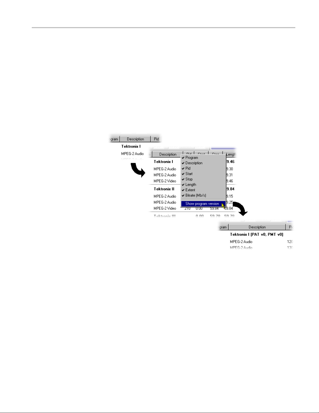
Views
Common Features
Columns in the C
preferences. Column management in the two Component views is similar.
Field Selection. You can select the fields to be displayed in each Component view.
The Header bar indicates which fi elds are currently displayed.
When you right-click on the Header bar, a menu is displayed. You can select
which fields are to be d isplayed. A check mark next to a field name indicates that
the field display is currently enabled.
You can display the version number of the PAT and PMT in the Description
column by enabling the Show program version option in the shortcut menu from
the Descr
iption column header.
omponent views can be sorted and rearranged to suit your
Similarly, you can display the PID numbers in hexadecimal, by selecting Display
exadecimal from the PID column shortcut menu.
in h
MTS400 Series Generator Applications User Manual 1–71
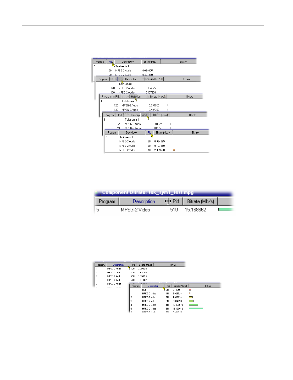
Views
Column Reposit
the column to the required position.
Column Width. You can resize Columns as required. Place the cursor over the
dividing line between two columns; it will change to the resizing cursor. Click
and drag the column to the required width. The change will be made to the
column to the left of the cursor.
ioning. You can reposition Columns as required. Click and drag
Double-clicking the column divider will automatically resize the column to the
left to the optimum size required to view the content.
Column Sort. You can sort Columns in ascending or descending order. Click the
cursor on the heading to sort the column. Clicking again will sort the column
in reverse order.
Similarly, the columns can be grouped in Program order, by clicking the Program
header.
1–72 MTS400 Series Generator Applications User Manual

Views
Common Menu Op
tions
The specifications for components of the various views can be manipulated by
options from the Edit m enu, View Menu, and Toolbar.
A shortcut menu also provides the Add, Modify, Delete, Import, Export and
Properties o ptions. Place the mouse pointer over the component to change and
click the ri
A typical shortcut menu is shown here:
The menu options are context-sensitive and will be enabled or disabled according
to the current selection in the view.
The following options are available from the various shortcut menus:
Add Adds a component to the currently selected
Modify Opens the properties dialog box.
Delete Deletes the currently selected component.
Properties
Export Payload
Export Elementary Stream Removes the transport stream and PES
Export Section Data
Import Section Data Imports SI data from a file and analyzes it.
ght mouse button to open the menu.
item.
Opens a properties dialog box for editing the
currently selected item.
Extracts and exports the payload of the
source transport stream in the form of a
simple data file.
headers and exports the remaining
information in the form of a simple data file.
Extracts and exports section data. The
created file can be imported as ES using
Multiplexer’s Add function or as SI using the
Import Section Data... option.
The section is added to the Navigator view.
MTS400 Series Generator Applications User Manual 1–73

Editing in the Navigator Views
EditingintheNavigatorViews
Multiplexer provides a variety of w ays of building and modifying transport
streams for multiplexing. In addition to the Menu Bar options and Toolbar
shortcuts bu
using f amiliar drag and drop Windows techniques.
ilt into the Multiplexer, many of the operations can be carried out
Dragging and Dropping
In the follo
are g iven at the head of the section, but only one method is described for each
action. Other methods for the same action often invoke the same dialog boxes and
sequence of follow-on actions.
To dra g a file, click on its name and hold down the left button of the mouse while
dragging the file to the required location. The cursor will change according to
the background that it is dragged over:
Note that as the file is dragged over elements in the Navigator, receptive elements
(elements where the file can be meaningfully dropped) will be highlighted.
wing descriptions, the alternative methods for carrying out a task
(With Ctrl key held) when dropped, the file will be
copied.
When dropped, the file will be moved (cut and
pasted).
ropped, no action will be taken.
When d
Transport Stream
Opening an MPEG File
Opening a Multiplexer File
Changing Transport
Stream Bit rate and
ration
Du
1–74 MTS400 Series Generator Applications User Manual
For information on Opening a Stream,(Seepage1-12.)
information on Opening a Stream ,(Seepage1-12.).
For
To specify a new bit rate or duration for the transport stream, select and highlight
the Transport Structure component in the Navigator view.
From the shortcut menu, select Properties. The dialog box will be displayed
as shown.

Editing in the Navigator Views
Programs
Edit the Bit rate and the Duration as required, then click the OK button.
The introduction of the Navigator Programs view has provided a more
program-centered means of manipulating SI/PSI. Whole programs can be added
to the multiplex and the application will update the associated tables, including
the PAT and PMT.
Note that the nodes of the tree structure in the Navigator Programs view are
context sensitive. When dragging and dropping files from either the Examine TS
window or from another instance of Multiplexer, a node will be highlighted as
the cursor passes over it only when the operation p roposed is valid. Note that
there may be a short delay before the node is highlighted while the legality of the
operation is checked.
MTS400 Series Generator Applications User Manual 1–75

Editing in the Navigator Views
Adding a New Program
With the Transp
selecting the Add option either from the shortcut menu (PAT highlighted in
Navigator Programs view) or the Menu Bar (Edit > Add) will open the Program
Wizard. (See page 1-33.)
ort Stream ID field highlighted in the Navigator Programs view,
Copying/Moving a Program
In the Navigator Programs view, the PAT is represented by the Transport Stream
ID field.
ds available:
Metho
Drag and drop (copy only) from the Examine TS window (Programs view) to
avigator Programs view.
the N
Drag and drop (copy/move) from another instance of Multiplexer to the
Navigator Programs view.
In the Navigator Programs view, programs can only be dropped onto the PAT node.
1–76 MTS400 Series Generator Applications User Manual

Tables
Editing in the Navigator Views
Adding a New PSI/SI Table
Methods available:
Highlight the PSI/SI Tables level in the Navigator Tables view and select
Add from the shortcut menu.
Drag and drop (copy only) from the Examine TS window (Tables view) to
the Navigator Tables view.
Drag and drop (copy/move) from another instance of Multiplexer to the
Navigator Tables view.
Any table that is defined in the selected standards, and not already present, can be
added the transport s tream. To add a table to the transport stream, click on PSI/SI
Tables in the N avigator Tables view:
1. Highlight the PSI/SI Tables level and select Add from the shortcut menu.
This will open the Select dialog box. The dialog box displays a list of the table
types that are not already present in the stream.
MTS400 Series Generator Applications User Manual 1–77

Editing in the Navigator Views
NOTE. A PAT table cannot be added when ISDB interpretation with Single
segment extension is selected.
2. Select the required table type and click OK.
Pressin
Only the table types that are not currently specified for the stream are listed. If
the req
box without affecting the specification for the stream.
The Se
ID need to be identified. Otherwise, the selected Table type is automatically
created.
g Cancel will abandon the operation without adding a new table.
uired table type is not listed, press the Cancel button to close the dialog
lect PID & Table ID dialog box is displayed only if a PID and/or Table
1–78 MTS400 Series Generator Applications User Manual

Editing in the Navigator Views
Copying a PSI/SI Table
A single section is automatically added to the newly created table type.
Methods available:
Drag and drop (copy only) from the Examine TS window (Tables view) to
the Navigator Tables view.
Drag and drop (copy/move) from another instance of Multiplexer to the
Navigator Tables view.
MTS400 Series Generator Applications User Manual 1–79

Editing in the Navigator Views
Deleting a PSI/SI Table
Exporting a Table
Importing a Table
Sections
Adding a New Section to a
PSI/SI Table
Tables can be co
available methods.
If a similar ta
copied table will be integrated with it.
A table is automatically removed when the last section is deleted (See page 1-87.)
For more inf
For more information, see Importing a Section.(Seepage1-88.)
Methods available:
Highlight the parent table level in the Navigator Tables view and select Add
from the shortcut menu.
Drag and drop (copy only) from the Examine TS window (Tables view) to
the Navigator Tables view.
pied (or moved) from existing multiplexes, using either of the
ble type is already present in the multiplex, the contents of the
ormation, see Exporting a Section.(Seepage1-87.)
Drag and drop (copy/move) from another instance of Multiplexer to the
Navigator Tables view.
To add a section to a table, select the parent table in the Navigator Tables view.
For example, to add a section to the SDT, select SDT Tables:
Then select Add from the shortcut menu.
1–80 MTS400 Series Generator Applications User Manual
 Loading...