


Tektronix MTS300 Reference manual

Technical Reference
MTS300 MPEG Test System
Hardware and Software Installation
071-0667-04
This document applies to firmware version 6.1.
Warning
The servicing instructions are for use by qualified
personnel only. To avoid personal injury, do not
perform any servicing unless you are qualified to
do so. Refer to all safety summaries prior to
performing service.
www.tektronix.com

Copyright © Tektronix, Inc. All rights reserved.
Tektronix products are covered by U.S. and foreign patents, issued and pending. Information in this publication supercedes
that in all previously published material. Spec ifications and price change privileges reserved.
Tektronix, Inc., P.O. Box 500, Beaverton, OR 97077
TEKTRONIX and TEK are registered trademarks of Tektronix, Inc.

WARRANTY
Tektronix warrants that the products that it manufactures and sells will be free from defects in materials and
workmanship for a period of one (1) year from the date of shipment. If a product proves defective during this
warranty period, Tektronix, at its option, either will repair the defecti ve product without charge for parts and labor,
or will provide a replacement in exchange for the defective product.
In order to obtain service under this warranty, Customer must notify Tektronix of the defect before the expiration
of the warranty period and make suitable arrangements for the performance of service. Customer shall be
responsible for packaging and shipping the defective product to the service center designated by Tektronix, with
shipping charges prepaid. Tektronix shall pay for the return of the product to Customer if the shipment is to a
location within the country in which the Tektronix service center is located. Customer shall be responsible for
paying all shipping charges, duties, taxes, and any other charges for products ret urned to any other locations.
This warranty shall not apply to any defect, failure or damage caused by improper use or improper or i nadequate
maintenance and care. Tektronix shall not be obligated to furnish service under this warranty a) to repai r damage
resulting from attempts by personnel other than Tektronix representatives to install, repair or service the product;
b) to repair damage resulting from improper use or connection to incompatible equipment; c) to repair any
damage or malfunction caused by the use of non-Tektronix supplies; or d) to service a product that has been
modified or integrated with other products when the effect of such modification or integration increases the time
or difficulty of servicing the product.
THIS W ARRANTY IS GIVEN BY TEKTRONIX IN LIEU OF ANY OTHER WARRANTIES, EXPRESS
OR IMPLIED. TEKTRONIX AND ITS VENDORS DISCLAIM ANY IMPLIED WARRANTIES OF
MERCHANTABILITY OR FITNESS FOR A PARTICULAR PURPOSE. TEKTRONIX’
RESPONSIBILITY TO REPAIR OR REPLACE DEFECTIVE PRODUCTS IS THE SOLE AND
EXCLUSIVE REMEDY PROVIDED TO THE CUSTOMER FOR BREACH OF THIS W ARRANTY.
TEKTRONIX AND ITS VENDORS WILL NOT BE LIABLE FOR ANY INDIRECT, SPECIAL,
INCIDENTAL, OR CONSEQUENTIAL DAMAGES IRRESPECTIVE OF WHETHER TEKTRONIX OR
THE VENDOR HAS ADVANCE NOTICE OF THE POSSIBILITY OF SUCH DAMAGES.


Table of Contents
Hardware Installation
First Time Operation
General Safety Summary v...................................
Service Safety Summary vii....................................
Related Documents ix...............................................
Contacting Tektronix xi.............................................
Hardware Installation 1--1......................................
Unpacking the MTS300 System 1--2.....................................
Accessories 1--2.................................................
Options 1--3.....................................................
Upgrades 1--5...................................................
Hardware Installation 1--6.............................................
Connecting MTS300 System I/O Ports 1--11...............................
Repackaging for Shipment 1--16.........................................
First Time Operation 2--1.......................................
Starting the MTS300 System 2--1.......................................
Shutting Down the MTS300 System 2--4.................................
Functional Check 2--7..........................................
10 MHz Reference Clock 2--7..........................................
Re m o v i n g t h e C a b i n e t 2 --- 8...........................................
I/O System 2--16.....................................................
MPEG-2 Software Components 2--23.....................................
TMCC Software Components 2--35......................................
Specifications
Specifications 3--1.............................................
Monitoring Characteristics 3--1.........................................
Interface Platform Characteristics 3--2...................................
I/O Port Electrical Characteristics 3--2...................................
Power Characteristics 3--11.............................................
Environmental Characteristics 3--11......................................
Mechanical (Physical) Characteristics 3--12................................
Certifications and Compliances 3--12.....................................
Software Repair and Recovery
Software Repair and Recovery 4--1...............................
Software Repair Strategy 4--1..........................................
Restoring System Settings 4--3.........................................
Restoring Device Drivers 4--17..........................................
Restoring the Operating System and Application Software 4--23...............
Index
MTS300 MPEG Test System Hardware and Software Installation Technical Reference
i

Table of Contents
List of Figures
Figure 1--1: Typical MTS300 test system rear panel connectors 1--7....
Figure 1--2: Keyboard and mouse alternative connections 1--8........
Figure 1--3: Software Key 1--9...................................
Figure 1--4: Rear-panel configuration with one ASI/M2S (Option AS)
interface installed 1--12......................................
Figure 1--5: Rear-panel configuration with two ASI/M2S (Option AS)
interfaces installed 1--12......................................
Figure 1--6: Rear-panel configuration with ASI/M2S (Option AS)
and SSI (Option SS) interfaces installed 1--13....................
Figure 1--7: Rear-panel configuration with ASI/M2S (Option AS)
and DHEI (Option DE) interfaces installed 1--13.................
Figure 1--8: Rear-panel configuration with ASI/M2S (Option AS)
and SPI (Option LV) interfaces installed 1--14...................
Figure 1--9: Rear-panel configuration with one SSI (Option SS)
interface installed 1--14......................................
Figure 1--10: Rear-panel configuration with two SSI (Option SS)
interfaces installed 1--15......................................
Figure 1--11: Rear-panel configuration with SSI (Option SS)
and ASI/M2S (MTS3FAS) interfaces installed 1--15...............
Figure 1--12: Repackaging the instrument (new packaging) 1--17.......
Figure 1--13: Repackaging the instrument (old packaging) 1--19.......
Figure 1--14: Placement of bottom spacer pad in inner shipping box 1--20
Figure 2--1: On/Stby switch 2--1.................................
Figure 2--2: Removing the cabinet handle 2--9......................
Figure 2--3: Removing the cabinet feet 2--9........................
Figure 2--4: Removing the circuit board retaining plate 2--10..........
Figure 2--5: Location of 10 MHz clock test point 2--11................
Figure 2--6: Removing the PIA+ module 2--13.......................
Figure 2--7: Adjusting the 10 MHz reference clock 2--14..............
Figure 2--8: Typical initial equipment setup 2--17....................
Figure 2--9: Tektronix MPEG Test System program window 2--18......
Figure 2--10: Connect to local Server Manager 2--18.................
Figure 2--11: Start the testing routine 2--19.........................
Figure 2--12: Begin the self test routine 2--19........................
Figure 2--13: Window showing sample test results summary 2--20......
Figure 2--14: Message box with connection requirements 2--21.........
ii
MTS300 MPEG Test System Hardware and Software Installation Technical Reference

Table of Contents
Figure 2--15: Connections for trigger test 2--22......................
Figure 2--16: Connections for clock test 2--22........................
Figure 2--17: ASI cabling 2--23....................................
Figure 2--18: Initial Master Client application window 2--24...........
Figure 2--19: Connecting to the local Server Manager 2--24............
Figure 2--20: Master Client window showing no assigned ports 2--25....
Figure 2--21: Port Manager panel showing Analysis Server selected 2--26
Figure 2--22: Selecting Launch Stream Player Client 2--26............
Figure 2--23: Stream Player Application window 2--27...............
Figure 2--24: C:\MTS300\Cfg-Trp directory 2--28....................
Figure 2--25: Starting transport stream analysis 2--29................
Figure 2--26: Master Client in Analysis mode 2--29...................
Figure 2--27: Expert Client application window 2--30................
Figure 2--28: Setup for testing second input 2--31....................
Figure 2--29: Exit Expert Client application 2--31....................
Figure 2--30: Expert Client application window 2--33................
Figure 2--31: Rear panel connections for I/O #3 test procedure 2--34....
Figure 2--32: Probes added in the TMCC Configuration Client 2--35....
Figure 2--33: TMCC Expert Client 2--36...........................
Figure 3--1: Parallel data timing, 188-byte packets 3--5..............
Figure 4--1: Deleting partitions using the Disk Administrator utility 4--7
Figure 4--2: Software Protection key 4--25..........................
Figure 4--3: Checking the free disk space 4--26......................
MTS300 MPEG Test System Hardware and Software Installation Technical Reference
iii

Table of Contents
List of Tables
T able 1--1: Standard accessories for the MTS300 system 1--2.........
Table 1--2: Optional accessories 1--3..............................
Table 1--3: MTS300 test system options 1--3.......................
Table 1--4: Possible interface configurations 1--4...................
Table 1--5: MTS300 test system upgrades 1--5.....................
Table 1--6: Rear-panel connectors 1--6............................
T able 1--7: Electrical operating requirements 1--9..................
T able 2--1: Adjustment table for 10 MHz reference clock 2--15.........
Table 3--1: Platform characteristics 3--2...........................
T a b l e 3 -- 2 : A S I 3 -- 2...........................................
Table 3--3: SPI-LVDS parallel (Option MTS3FLV) 3-- 3.............
Table 3--4: LVDS parallel data pin connections 3-- 5.................
Table 3--5: SSI (Option SS) 3--6.................................
Table 3--6: DHEI-Digicipher II 3--7..............................
Table 3--7: DHEI Expansion In pin connections 3--9................
Table 3--8: DHEI Expansion Out pin connections 3-- 10..............
T able 3--9: AC power source characteristics 3--1 1....................
T able 3--10: Environmental characteristics 3--1 1....................
T able 3--11: Mechanical characteristics 3--12.......................
Table 3--12: Certifications and compliances 3--12....................
Table 3--13: Environmental limits and use classification for safety
certification compliance 3--13.................................
Table 4--1: MTS300 system COM port settings 4--8.................
Table 4--2: Touchscreen driver hardware settings 4--22...............
iv
MTS300 MPEG Test System Hardware and Software Installation Technical Reference

General Safety Summary
Review the following safety precautions to avoid injury and prevent damage to
this product or any products connected to it. To avoid potential hazards, use this
product only as specified.
Only qualified personnel should perform service procedures.
While using this product, you may need to access other parts of the system. Read
the General Safety Summary in other system manuals for warnings and cautions
related to operating the system.
ToAvoidFireor
Personal Injury
Use Proper Power Cord. Use only the power cord specified for this product and
certified for the country of use.
Ground the Product. This product is grounded through the grounding conductor
of the power cord. To avoid electric shock, the grounding conductor must be
connected to earth ground. Before making connections to the input or output
terminals of the product, ensure that the product is properly grounded.
Observe All Terminal Ratings. To avoid fire or shock hazard, observe all ratings
and markings on the product. Consult the product manual for further ratings
information before making connections to the product.
Do not apply a potential to any terminal, including the common terminal, that
exceeds the maximum rating of that terminal.
Do Not Operate Without Covers. Do not operate this product with covers or panels
removed.
Use Proper Fuse. Use only the fuse type and rating specified for this product.
Avoid Exposed Circuitry. Do not touch exposed connections and components
when power is present.
Wear Eye Protection. Wear eye protection if exposure to high-intensity rays or
laser radiation exists.
Do Not Operate With Suspected Failures. If you suspect there is damage to this
product, have it inspected by qualified service personnel.
Do Not Operate in Wet/Damp Conditions.
Do Not Operate in an Explosive Atmosphere.
Keep Product Surfaces Clean and Dry.
Provide Proper Ventilation. Refer to the manual’s installation instructions for
details on installing the product so it has proper ventilation.
MTS300 MPEG Test System Hardware and Software Installation Technical Reference
v
General Safety Summary
Symbols and Terms
Terms in this Manual. These terms may appear in this manual:
WARNING. Warning statements identify conditions or practices that could result
in injury or loss of life.
CAUTION. Caution statements identify conditions or practices that could result in
damage to this product or other property.
Terms on the Product. These terms may appear on the product:
DANGER indicates an injury hazard immediately accessible as you read the
marking.
WARNING indicates an injury hazard not immediately accessible as you read the
marking.
CAUTION indicates a hazard to property including the product.
Symbols on the Product. The following symbols may appear on the product:
CAUTION
Refer to Manual
Protective Ground
(Earth) Terminal
vi
MTS300 MPEG Test System Hardware and Software Installation Technical Reference

Service Safety Summary
Only qualified personnel should perform service procedures. Read this Service
Safety Summary and the General Safety Summary before performing any service
procedures.
Do Not Service Alone. Do not perform internal service or adjustments of this
product unless another person capable of rendering first aid and resuscitation is
present.
Disconnect Power. To avoid electric shock, switch off the instrument power, then
disconnect the power cord from the mains power.
Use Care When Servicing With Power On. Dangerous voltages or currents may
exist in this product. Disconnect power, remove battery (if applicable), and
disconnect test leads before removing protective panels, soldering, or replacing
components.
To avoid electric shock, do not touch exposed connections.
MTS300 MPEG Test System Hardware and Software Installation Technical Reference
vii

Service Safety Summary
viii
MTS300 MPEG Test System Hardware and Software Installation Technical Reference

Preface
This manual provides installation and first-time operating instructions for the
MTS300 MPEG Test Systems software version 6.1.
The individual sections of this manual provide specific information on the
following topics:
H The Hardware Installation section contains basic instructions on how to
install and operate the test system.
H The First Time Operation section contains procedures to verify the test
system is functioning properly.
H The Specifications section lists the electrical characteristics of the platform,
I/O system, and the Synchronous Serial Interface. This section also includes
environmental and physical characteristics and repackaging information.
H The Software Repair and Recovery section contains procedures to trouble-
shoot and restore the operating system and device drivers and reinstall the
MTS300 applications software.
For the latest information about MTS300 system software features and bugs,
refer to the MPEG Test System Software Version 6.1 Read This First document,
Tektronix part number 071-0666-XX, that accompanied your test system,
software product, or upgrade.
Related Documents
For additional information about using MTS300 system software to monitor,
analyze, and generate MPEG-2, DVB, and ATSC data streams, refer to the
following manuals:
The MTS300 MPEG Test System Real-Time Analysis User Manual, Tektronix
part number 071-0658-XX, contains information about using the Real-Time
MPEG-2 Analyzer application.
The MTS300 MPEG Test System MPEG-2 DVB/ATSC/ISDB-S/ARIB System
Analyzer User Manual, Tektronix part number 071-0659-XX, contains information about using the Deferred-Time Analyzer and DVB Channel Coding and
Decoding applications.
The MTS300 MPEG Test System Program Stream Analyzer User Manual,
Tektronix part number 071-0662-XX, contains information about using the
deferred-time Program Stream Analyzer application.
MTS300 MPEG Test System Hardware and Software Installation Technical Reference
ix

Preface
The MTS300 MPEG Test System Stream Creation Applications User Manual,
Tektronix part number 071-0778-XX, contains information about using the
Multiplexer, DVB Table Editor, ATSC Table Editor, DVB Channel Coding and
Decoding, Jitter Adder, Error Injector, and Open MUX Controller applications.
The MTS300 MPEG Test System Dolby Digital Audio Stream Analyzer User
Manual, Tektronix part number 071-0661-XX, contains information about using
the deferred-time AC-3 Audio Stream Analyzer application.
The MTS300 MPEG Test System Audio Stream Analyzer User Manual, Tektronix
part number 071-0663-XX, contains information about using the deferred-time
MPEG Audio Stream Analyzer application.
The MTS300 MPEG Test System Video Stream Analyzer User Manual, Tektronix
part number 071-0664-XX, contains information about using the deferred-time
MPEG Video Stream Analyzer application.
The MTS300 MPEG Test Options User Manual, Tektronix part number
1000-3031, contains information about using the Data Broadcast Carousel
Analyzer application, the Elementary Stream Analyzer application, and the
Multiplexer application.
For additional information about test system maintenance and repair, refer to the
optional MTS300 MPEG Test System Service Manual, Tektronix part number
071-0668-XX. Contact your nearest Tektronix representative or field office for
ordering information.
For additional information about the Windows NT operating system, refer to the
online help provided with the test system.
x
MTS300 MPEG Test System Hardware and Software Installation Technical Reference

Contacting Tektronix
Preface
Phone 1-800-833-9200*
Address Tektronix, Inc.
Department or name (if known)
14200 SW Karl Braun Drive
P.O. Box 500
Beaverton, OR 97077
USA
Web site www.tektronix.com
Sales support 1-800-833-9200, select option 1*
Service support 1-800-833-9200, select option 2*
Technical support Email: techsupport@tektronix.com
1-800-833-9200, select option 3*
6:00 a.m. -- 5:00 p.m. Pacific time
* This phone number is toll free in North America. After office hours, please leave a
voice mail message.
Outside North America, contact a Tektronix sales office or distributor; see the
Tektronix Web site for a list of offices.
MTS300 MPEG Test System Hardware and Software Installation Technical Reference
xi

Preface
xii
MTS300 MPEG Test System Hardware and Software Installation Technical Reference

Hardware Installation


Hardware Installation
This section contains the following information:
H Unpacking the MTS300 system
H Hardware installation
H Repackaging the MTS300 system for shipment
For information on generating and analyzing MPEG transport streams, refer to
the MTS300 system user manuals. See page ix for a list of the available manuals.
Refer to First Time Operation on page 2--1 for instructions on how to verify
basic instrument operation after the MTS300 system has been installed.
MTS300 MPEG Test System Hardware and Software Installation Technical Reference
1- 1

Hardware Installation
Unpacking the MTS300 System
The tables in this section list the standard and optional accessories available for
the MTS300 system.
NOTE. You must use the original box and packaging when returning your test
system to Tektronix. In the event shipping is required for upgrade or repair, refer
to Packaging for Shipment on page 1--16.
Accessories
Table 1--1 lists the standard accessories that are shipped with your MTS300
system. Use this list to ensure that your order is complete.
Table 1- 1: Standard accessories for the MTS300 system
Quantity Description Part number
1ea Read This First 071-0666-XX
1ea MTS300 MPEG Test System Hardware and Software
Installation Technical Reference (this manual)
1ea MTS300 MPEG Test System Real-Time Analysis User
Manual (includes 063-3325-XX CD-ROM)
1ea MTS300 MPEG Test System Stream Creations User
Manual
1ea Applications software recovery disc (supplied with
071-0658-XX manual)
1ea Operating system recovery disc 063-3366-XX
1ea License Password document
Note: Keep this document in a safe place. You will need it
if you ever have to reinstall your software.
1ea Power cord (North American) 161-0066-00
071-0667-XX
071-0658-XX
071-0778-XX
063-3325-XX
(not orderable)
063-3158-XX
1- 2
1ea Stylus (for use with the touchscreen) 119-6107-XX
1ea SCSI terminator (installed on the t est syst em) 650-4062-XX
1ea Front panel cover 200-4408-XX
1ea Emergency backup disk (floppy disk)
1ea Mouse
1ea Keyboard
1ea Statement of ISO Compliance (in envelope)
MTS300 MPEG Test System Hardware and Software Installation Technical Reference

Hardware Installation
Table 1--2 lists the optional accessories you can order for your MTS300 system.
See your Tektronix representative for help ordering these optional accessories.
Table 1- 2: Optional accessories
Description Part number
MTS300 MPEG Test System Service Manual 071-0668-XX
Rackmount cabinet conversion kit w ith instructions 016-1921-XX
Power cord options:
Option A1 Universal Euro 161-0066-09
Option A2 United Kingdom 161-0066-10
Option A3 Australian 161-0066-11
Option A5 Swiss 161-0154-00
Options
Table 1--3 lists the options available when you purchase the test system.
Table 1--4 lists the possible interface configurations.
Table 1- 3: MTS300 test system options
Category Option Description
MTS300 Basic instru-
ment
Interface
1
Option AS ASI/M2S asynchronous serial interface
Option DE DHEI (GI-Digicypher) interface
Option LV SPI (LVDS) sychronous parallel interface
Option SS SSI (SMPTE310M) synchronous serial interface
Test System with at least one user-selected interface and the
following client applications:
Master Client
Expert Client
TMCC Expert Client
Configuration Client
TMCC Configuration Client
Stream Player Client
Stream Recorder Client
The MTS300 also comes with the Private Syntax Interpreter
and the Jitter Adder applications.
2
2
MTS300 MPEG Test System Hardware and Software Installation Technical Reference
1- 3

Hardware Installation
Table 1- 3: MTS300 test system options (Cont.)
Category DescriptionOption
Software Option DA Deferred-Time Analysis System (user manual 071-0659-XX),
which includes the following applications:
MPEG-2 DVB/ATSC/ISDB-S/ARIB System Analyzer
TMCC Deferred-Time Analyzer
MPEG-2 DVB/ATSC/ISDB-S/ARIB Multiplexer
DVB Table Editor
ATSC Table Editor
ARIB Table Editor
DVB Channel Coding and Decoding
Error Injector
Option AC3 Dolby Digital (AC-3) Analyzer (user manual 071-0661-XX)
Option OC ViAccess Conditional Access (requires Option DT)
Option OM OpenMuxTMReal-Time Multiplexer (user manual 071-0778-XX)
Option ES MPEG Audio and MPEG Video Elementary Stream Analyzers
(user manuals 071-0663-XX and 071-0664-XX)
Option PS Program Stream Analyzer (user manual 071-0662-XX)
Option TM TMCC Combiner
1
Each hardware interface option adds two input/output pairs, clock, and trigger
connections. The test system maximum capacity is any two interface options except
as noted in Table 1 - 4.
2
The SPI (LVDS) and DHEI (GI-Digicypher) interfaces can only be ordered when you
order an ASI/M2S interface.
Table 1- 4: Possible interface configurations
First mezzanine Second mezzanine (one of the following)
ASI/M2S interface None
ASI/M2S interface
SMPTE310M (SSI) interface
DHEI (GI-Digicypher) interface
SPI (LVDS) interface
1
SSI (SMPTE310M) interface None
SSI (SMPTE310M) interface
ASI/M2S interface
1
The SPI (LVDS) and DHEI (GI-Digicypher) interfaces can only be ordered when you
2
order an ASI/M2S interface.
2
This configuration is only available when you install the MTS3FAS hardware upgrade
into an existing MTS300 with an SSI (SMPTE310M) interface.
1
1- 4
MTS300 MPEG Test System Hardware and Software Installation Technical Reference

Hardware Installation
Upgrades
Table 1--5 lists the upgrades available for an existing MTS300 MPEG Test
System. You can order some of these upgrades when you purchase your
instrument and they will be installed at the factory.
NOTE. All of the MTS300 upgrade kits require that you run the Sales Wizard file
MTS3WIZ.ZIP. The latest version is available from www.tektronix.com.
Table 1- 5: MTS300 test system upgrades
Category Part number Description
Interface
Software MTS3FDA Adds Deferred-Time Analysis System to existing MTS300
1
MTS3FAS Adds ASI/M2S interface to existing MTS300
MTS3FDE Adds DHEI (GI-Digicypher) interface to existing MTS300
MTS3FLV Adds SPI (LVDS) sychronous parallel interface to existing
MTS300
MTS3FSS Adds SSI (SMPTE310M) synchronous serial interface to
existing MTS300
MTS3FAC Adds Dolby Digital (AC--3) Analyzer to existing MTS300
MTS3FOC Adds ViAccess Conditional Access to existing MTS300
MTS3FOM Adds Real-Time Multiplexing (Open Mux) to existing
MTS300
MTS3FES Adds MPEG Audio/Video Elementary Stream Analyzers to
existing MTS300
MTS3FPS Adds Program Stream Analyzer to existing MTS300
MTS3FTM Adds TMCC Combiner to existing MTS300
MTS3FDB Adds Data Broadcast Carousel Analyzer to existing
MTS300
MTS3FIN Adds Elementary S tream Analyzer for all MPEG-1 and
MPEG-2 transport streams to existing MTS300
MTS3FMX Adds off-line Multiplexer to existing MTS300
1
Each interface option adds two input/output pairs, clock, and trigger connections.
The test system maximum capacity is any two interface options except as noted in
Table 1- 4.
MTS300 MPEG Test System Hardware and Software Installation Technical Reference
1- 5

Hardware Installation
Hardware Installation
This section provides instructions for installing the MTS300 system and making
the necessary electrical connections. The MTS300 system can be operated from a
bench or installed in a rack using the optional rack-mount kit. The rack-mount
kit includes installation instructions.
CAUTION. For proper cooling, provide at least two inches (5.1 cm) of clearance
at the rear and to the sides of the test system, and ensure that the air temperature
at all air intake vents (inside of the equipment rack) does not exceed 40
°C.
Use the two collapsible front feet on the bottom of the MTS300 system to
change the height of the front panel.
Test System
Interconnections
The location of the connectors on a typical test system rear panel is shown
Figure 1--1. Table 1--6 describes the transport stream, network, and peripheral
device connectors. Refer to Connecting the MTS300 System I/O Ports on
page 1--11 for illustrations of the various rear-panel connector configurations.
Table 1- 6: Rear-panel connect ors
Connector Description
Transport stream input/out put
ASI/M2S Input/Output
SPI (LVDS) Input/Output
DHEI (GI Digicypher)
Input/Output
SSI Input/Output
Monitor 15-pin female high density-D-sub connector for SVGA
Keyboard Mini-DIN connectors for PS2 compatible keyboard (on rear
Mouse Mini-DIN connectors for PS2 compatible mouse (on rear and
Each format includes two input/output pairs
monitor
and side panels)
side panels)
1- 6
Printer 25-pin sub-D connector for parallel communi cation
LAN (Ethernet) 10 Base-T/100 Base-T, RJ45 connector for Ethernet
communications
RS-232/422 9-pin D-sub type connector for serial communication
SCSI Standard, PC compatible Ultra-Wide SCSI port, 68 Pins
MTS300 MPEG Test System Hardware and Software Installation Technical Reference

Power
ASI I/O
SPI (LVDS) I/O
(Option LV or MTS3FLV)
Hardware Installation
Ethernet
Parallel Port
RS-232
COM Port 1
Figure 1- 1: Typical MTS300 test system rear panel connectors
SCSI
MouseKeyboardSVGA
MTS300 MPEG Test System Hardware and Software Installation Technical Reference
1- 7

Hardware Installation
The following procedure identifies the electrical connections.
1. Plug in the keyboard and mouse to the proper rear panel connectors. Refer to
Figure 1--1. Figure 1--2 shows alternative connectors for a mouse and
keyboard. The optional connections are located on the instrument side panel.
Earphones
USB
Keyboard
Mouse
Figure 1- 2: Keyboard and mouse alternative connections
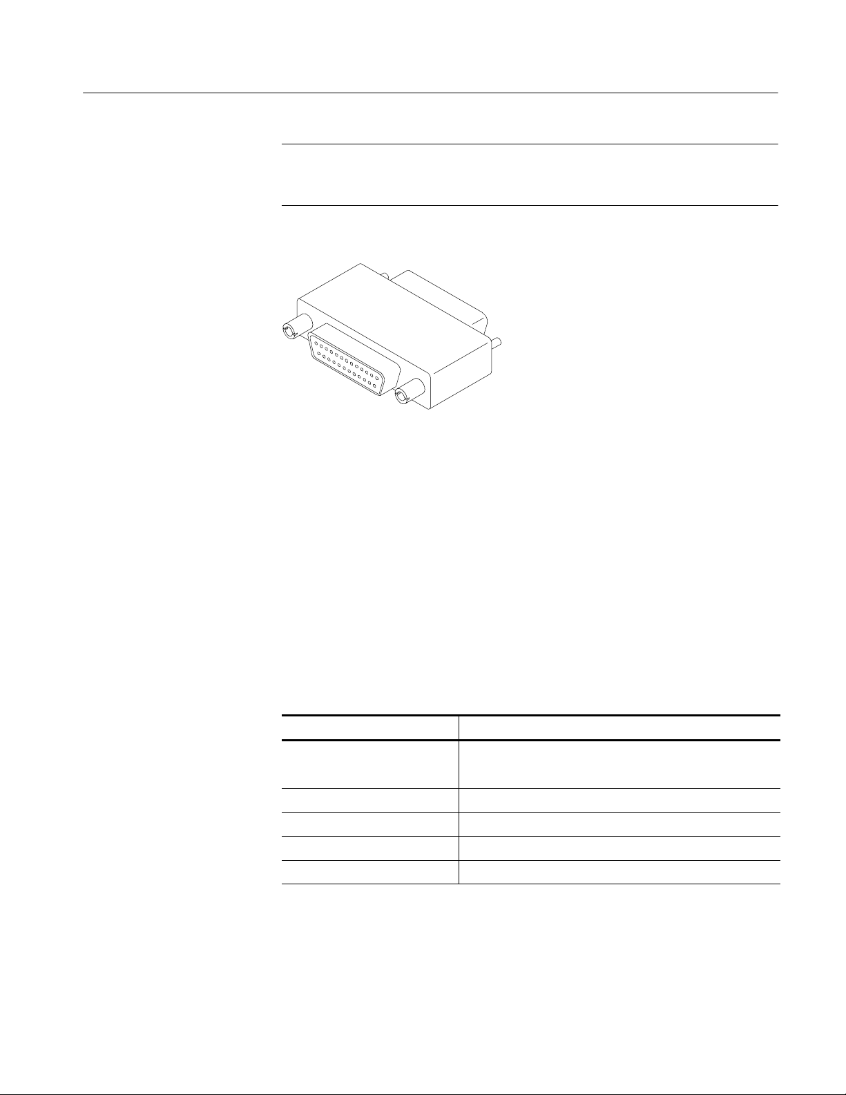
2. Install the Software Key on the rear panel Parallel port. MTS300 MPEG Test
System software applications will not run without the Software Key
installed; do not remove or misplace the Software Key.
To use the Parallel port with the Software Key installed, attach any parallel
port cables (such as a printer) directly to the Software Key. The Software
Key does not interfere with parallel communications.
1- 8
MTS300 MPEG Test System Hardware and Software Installation Technical Reference
Hardware Installation
NOTE. To run MTS300 MPEG Test System applications, the Software Key must
be on the computer Parallel port. If you return the test system to a Tektronix
Service Center for upgrade or repair, include the Software Key.
Figure 1- 3: Software Key
Supplying Power
The MTS300 MPEG Test System platform is designed to operate from a
single-phase power source having one of its current carrying conductors at or
near earth ground (the neutral conductor). Power sources that have both current
carrying conductors live with respect to ground, such as phase-to-phase or
multiphase systems, are not recommended. A protective ground connection, by
way of the grounding conductor in the power cord, is essential for safe operation.
The electrical operating requirements are listed in Table 1--7.
Table 1- 7: Electrical operating requirements
Requirement Specification
Source Voltage 100 VAC to 240 VAC
47 Hz to 63 Hz
Fuse Rating 10 A Fast / 250 V
Maximum Power Consumption 170 Watts typical
Inrush Surge Current 36 Amps maximum
Power Factor Correction Yes
MTS300 MPEG Test System Hardware and Software Installation Technical Reference
1- 9
Hardware Installation
After you have installed the MTS300 system and completed making the signal,
network, and peripheral connections, plug the power cord into the mains. See
Figure 1--1 for location of power connector.
CAUTION. Do not supply power to the instrument until all connections have been
made.
WARNING. The test system is designed for connection to an earth-grounded AC
outlet. To avoid risk of electrical shock or equipment damage, do not disable the
grounding plug.
Mains Voltage Range. You can power the test system computer and monitor from
mains that supply between 100 VAC and 240 VAC without setting a voltage
selection switch.
Mains Frequency. The test system computer and monitor operate on either 50 Hz
or 60 Hz line frequencies.
CAUTION. To prevent damage, protect the system computer from power fluctuations and temporary interruptions with a regulating noninterruptible power
supply. This device protects the hardware from damage caused by power surges
and voltage spikes. In addition, it allows the system to operate temporarily
during a power failure.
Power Cord Options. Unless a specific power cord option is ordered, the system
computer and monitor come standard with a power cord for North American
60 Hz, 120 VAC supplies. Table 1--2 on page 1--3 lists the power cord options.
1- 10
MTS300 MPEG Test System Hardware and Software Installation Technical Reference

Connecting MTS300 System I/O Ports
Figure 1--4 through Figure 1--11 show the available input and output (I/O)
connector configurations on the MTS300 rear panel. For I/O port specifications,
refer to the Specifications section beginning on page 3-1. Use the I/O ports that
best suit your operating environment and signal sources. A description of each
connector type follows.
Hardware Installation
Input
Trigger Input
Clock Input
Output to Other
Equipment
You must provide input to the MTS300 system to monitor an MPEG-2, DVB, or
ATSC bit stream. The MTS300 system I/O ports can be ASI serial, SPI (LVDS),
DHEI (GI-Digicypher), or SSI (SMPTE310M). To change the configuration,
refer to Configuration Client Reference in the MTS300 MPEG Test System
Real-Time Analysis User Manual.
The trigger input accepts a TTL level (0 to +5 V) signal you can use to control
capture of the MTS300 system input stream to the system disks. You can
configure the system to start/stop data capture on either the rising edge (low to
high transition) or the falling edge (high to low transition) of the trigger signal.
Refer to the MTS300 MPEG Test System Real-Time Analysis User Manual for
further information on capturing transport stream inputs.
Each output port has a corresponding clock input which can be used to clock the
transport stream output when using Stream Player. The clock rate is at the byte
rate of the transport stream for the ASI/M2S and SPI (LVDS) formats. The clock
rate is at the bit rate of the transport stream for the SMPTE310M (SSI) and
DHEI (GI Digicypher) formats.
Applications generating an output will do so on the I/O port to which the
application has been assigned. Applications requiring an input have an output
activation option that will loop-through the input signal to the output connector
on the assigned I/O port.
When an output port is used to generate signals using the Stream Player or
OpenMux applications, the corresponding input port cannot be used.
MTS300 MPEG Test System Hardware and Software Installation Technical Reference
1- 11

Hardware Installation
ASI/M2S I/O
Figure 1- 4: Rear-panel configuration with one ASI/M2S (Option AS) interface installed
ASI/M2S I/O ASI/M2S I/O
Figure 1- 5: Rear-panel configuration with two ASI/M2S (Option AS) interfaces installed
1- 12
MTS300 MPEG Test System Hardware and Software Installation Technical Reference